WO2012161416A2 - Gps 수신기의 위치 계산 방법, 그 방법을 구현하기 위한 프로그램이 기록된 기록매체 및 gps 수신기 - Google Patents
Gps 수신기의 위치 계산 방법, 그 방법을 구현하기 위한 프로그램이 기록된 기록매체 및 gps 수신기 Download PDFInfo
- Publication number
- WO2012161416A2 WO2012161416A2 PCT/KR2012/002263 KR2012002263W WO2012161416A2 WO 2012161416 A2 WO2012161416 A2 WO 2012161416A2 KR 2012002263 W KR2012002263 W KR 2012002263W WO 2012161416 A2 WO2012161416 A2 WO 2012161416A2
- Authority
- WO
- WIPO (PCT)
- Prior art keywords
- satellite signal
- signal group
- gps
- satellite
- low error
- Prior art date
- Legal status (The legal status is an assumption and is not a legal conclusion. Google has not performed a legal analysis and makes no representation as to the accuracy of the status listed.)
- Ceased
Links
Images




Classifications
-
- G—PHYSICS
- G01—MEASURING; TESTING
- G01S—RADIO DIRECTION-FINDING; RADIO NAVIGATION; DETERMINING DISTANCE OR VELOCITY BY USE OF RADIO WAVES; LOCATING OR PRESENCE-DETECTING BY USE OF THE REFLECTION OR RERADIATION OF RADIO WAVES; ANALOGOUS ARRANGEMENTS USING OTHER WAVES
- G01S19/00—Satellite radio beacon positioning systems; Determining position, velocity or attitude using signals transmitted by such systems
- G01S19/01—Satellite radio beacon positioning systems transmitting time-stamped messages, e.g. GPS [Global Positioning System], GLONASS [Global Orbiting Navigation Satellite System] or GALILEO
- G01S19/13—Receivers
- G01S19/22—Multipath-related issues
-
- G—PHYSICS
- G01—MEASURING; TESTING
- G01S—RADIO DIRECTION-FINDING; RADIO NAVIGATION; DETERMINING DISTANCE OR VELOCITY BY USE OF RADIO WAVES; LOCATING OR PRESENCE-DETECTING BY USE OF THE REFLECTION OR RERADIATION OF RADIO WAVES; ANALOGOUS ARRANGEMENTS USING OTHER WAVES
- G01S19/00—Satellite radio beacon positioning systems; Determining position, velocity or attitude using signals transmitted by such systems
- G01S19/01—Satellite radio beacon positioning systems transmitting time-stamped messages, e.g. GPS [Global Positioning System], GLONASS [Global Orbiting Navigation Satellite System] or GALILEO
- G01S19/13—Receivers
- G01S19/20—Integrity monitoring, fault detection or fault isolation of space segment
Definitions
- the present invention relates to a method for calculating a position of a GPS receiver, a recording medium on which a program for implementing the method is recorded, and a GPS receiver.
- GPS Global Positioning System
- GPS technology is mainly used as a position measuring system for automobile navigation systems, and related industries and markets are continuously expanding.
- the satellite signals of GPS which uses radio waves, have various errors such as ionospheric delay, tropospheric delay, receiver clock bias, thermal noise, and reflection. Ingredients are included.
- the DGPS Different Global Positioning System
- the DGPS is used to correct the position error and increase the positioning accuracy by minimizing the influence of the error component included in the satellite signal.
- a GPS module for correcting a position error using DGPS to increase a position resolution and a DGPS receiving apparatus using the same are disclosed.
- DGPS Error components due to ionospheric delay, tropospheric delay, receiver clock bias, and thermal noise can be significantly reduced by DGPS.
- a reflection error an error due to reflection
- its characteristics are different from those of the error factors listed above, and thus a reflection error cannot be removed by a technique such as a conventional DGPS.
- 1 is a diagram illustrating a process of generating a reflection error.
- the reflection error is a position error generated by inputting the satellite signal transmitted from the satellite to the GPS receiver 1 after being reflected by surrounding buildings or the ground surface.
- GPS satellite signals cannot pass through the building. If buildings are lined up on both sides of the road, it may appear that GPS satellite signals are received in both directions, but the GPS satellite signals reflected from the opposite building may be received.
- the strength of the GPS satellite signal reflected from the building is almost indistinguishable from the non-reflected GPS satellite signal, which means that the strength of the reflected GPS satellite signal should theoretically be small, but the distance of the GPS satellites depends on the layout. For example, the GPS satellite signals from the distant GPS satellites have low signal strength.
- Reflection errors are larger in larger cities with tall buildings and wide roads, and typically have errors corresponding to road widths.
- the method of removing the reflection error includes an adaptive antenna array method, but the problem that it is difficult to apply in a mobile device due to the need to use a plurality of antennas. there was.
- the background art described above is technical information possessed by the inventors for the derivation of the present invention or acquired during the derivation process of the present invention, and is not necessarily a publicly known technique disclosed to the general public before the application of the present invention.
- the present invention provides a method for calculating a position of a GPS receiver capable of calculating the position of a current GPS receiver more accurately by removing the reflection error by excluding a GPS satellite causing a reflection error from a position calculation, and a program for implementing the method.
- a method for calculating a position of a GPS receiver capable of calculating the position of a current GPS receiver more accurately by removing the reflection error by excluding a GPS satellite causing a reflection error from a position calculation, and a program for implementing the method.
- the present invention by combining the GPS satellites into a plurality of satellite signal group, by finding the position coordinates that do not include the reflection error of the position coordinates of each satellite group, the position calculation of the GPS receiver that can measure the position of the GPS receiver accurately
- a recording medium and a GPS receiver in which a program for implementing the method is recorded.
- a method for calculating the position of a GPS receiver and a recording medium having recorded thereon a program for performing the same is provided.
- a method of calculating a position of a GPS receiver may include: generating a plurality of satellite signal groups by combining a plurality of GPS satellite signals received through a receiver, in the GPS satellite signals included in each satellite signal group. Selecting a low error satellite signal group that does not include or minimally includes a GPS satellite signal causing a reflection error by using pseudorange, and reflects a GPS satellite signal not included in the low error satellite signal group Detecting the satellite signal and calculating position coordinates of the GPS receiver using the remaining GPS satellite signals except for the reflected satellite signal.
- the generating of the plurality of satellite signal groups may generate k C m satellite signal groups according to a combination of m GPS satellite signals as one satellite signal group when k GPS satellite signals are received. It may be an integer greater than or equal to 4, and k may be an integer greater than m.
- the generating of the plurality of satellite signal groups may combine the plurality of GPS satellite signals to generate satellite signal groups having a relatively low dilution of precision (DOP).
- DOP dilution of precision
- the selecting of the low error satellite signal group may include at least one of an estimated position coordinate of the GPS receiver, a residual of the pseudo distance, a correction value, and a deviation of the pseudo distance and the geometric distance calculated using the pseudo distance.
- the low error satellite signal group may be selected based on a result of calculating a pseudo-range related variable including a.
- the step of selecting the low error satellite signal group is estimated for each satellite signal group using the pseudo distance by the GPS satellite signals included in each satellite signal group.
- the satellite signal group corresponding to the estimated position coordinates separated from each other may be selected as the low error satellite signal group.
- the selecting of the low error satellite signal group may include calculating an average coordinate of an expected position coordinate of each satellite signal group, and calculating a satellite signal group having an estimated position coordinate whose deviation from the average coordinate is greater than or equal to a reference value. Can be selected by group.
- selecting the low error satellite signal group is representative of a distance deviation for each GPS satellite signal included in the satellite signal group for each satellite signal group. The value may be calculated, and the satellite signal group having the minimum representative value of the distance deviation may be selected as the low error satellite signal group.
- selecting the low error satellite signal group may include selecting a plurality of low error satellite signal groups at one time, and detecting the reflected satellite signal by using the plurality of low error satellite signals.
- a plurality of GPS satellite signals not included in each satellite signal group may be detected as the reflected satellite signals.
- a method of calculating a position of a GPS receiver may include: generating a plurality of satellite signal groups by combining a plurality of GPS satellite signals received through a receiver in a control unit, and performing GPS satellite signals included in each satellite signal group. Selecting a low error satellite signal group that does not include a GPS satellite signal causing a reflection error by using a pseudo distance, and calculating the position coordinates of the GPS receiver based on the estimated position coordinates calculated from the low error satellite signal group; Steps.
- the step of selecting the low error satellite signal group is to calculate the predicted position coordinates for each of the satellite signal groups using the pseudo-distance by the GPS satellite signals included in each satellite signal group, and compared with other estimated position coordinates
- the satellite signal group corresponding to the distant expected position coordinates may be selected as the low error satellite signal group.
- the selecting of the low error satellite signal group may include calculating an average coordinate of an expected position coordinate of each satellite signal group, and calculating a satellite signal group having an estimated position coordinate whose deviation from the average coordinate is greater than or equal to a reference value. Can be selected by group.
- a combination unit for generating a plurality of satellite signal groups by combining a plurality of GPS satellite signals received through the receiver, using pseudo distances by GPS satellite signals included in each satellite signal group Satellite signal group selection unit for selecting a low error satellite signal group that does not include or minimize the GPS satellite signal causing a reflection error, and detects a GPS satellite signal not included in the low error satellite signal group as a reflected satellite signal.
- a GPS receiver including a satellite signal detector and a position calculator for calculating position coordinates of the GPS receiver using the remaining GPS satellite signals other than the reflected satellite signal is provided.
- the combination unit generates k C m satellite signal groups according to a combination of m GPS satellite signals as one satellite signal group when k GPS satellite signals are received, where m is an integer of 4 or more, and k is m. It can be a larger integer.
- the combining unit may combine the plurality of GPS satellite signals to generate satellite signal groups having a relatively low DOP.
- the satellite signal group selector may include a pseudo-range related variable including at least one of an estimated position coordinate of the GPS receiver, a residual of the pseudo-range, a correction value, and a deviation between the pseudo-range and a geometrical distance calculated using the pseudo-range.
- the low error satellite signal group may be selected based on the calculated result.
- the satellite signal group selector calculates an estimated position coordinate for each satellite signal group using pseudo distances based on GPS satellite signals included in each satellite signal group. For example, the low-order satellite signal group may be selected as the satellite signal group corresponding to the anticipated position coordinates separated from each other when compared with other expected position coordinates.
- the satellite signal group selector may calculate an average coordinate of estimated position coordinates of each satellite signal group, and select a satellite signal group having an estimated position coordinate whose deviation from the average coordinate is greater than or equal to a reference value as the low error satellite signal group. have.
- the satellite signal group selector calculates a representative value of the distance deviation for each GPS satellite signal included in the satellite signal group for each satellite signal group, The satellite signal group having the smallest representative value of the distance deviation may be selected as the low error satellite signal group.
- the satellite signal group selector selects a plurality of low error satellite signal groups at a time, and the satellite signal detector includes a plurality of low error satellite signal groups that are not included in each of the plurality of low error satellite signal groups. GPS satellite signals can be detected as reflected satellite signals.
- a GPS receiver comprising a position calculator.
- the satellite signal group selector calculates an estimated position coordinate for each satellite signal group by using pseudo distances from GPS satellite signals included in each satellite signal group, and compares the estimated position coordinates to the estimated position coordinates that are separated from other estimated position coordinates.
- a corresponding satellite signal group may be selected as the low error satellite signal group.
- the satellite signal group selector may calculate an average coordinate of estimated position coordinates of each satellite signal group, and select a satellite signal group having an estimated position coordinate whose deviation from the average coordinate is greater than or equal to a reference value as the low error satellite signal group. have.
- the GPS satellite causing the reflection error is excluded from the position calculation, thereby removing the reflection error to more accurately calculate the position of the current GPS receiver.
- 1 is a view showing a generation process of reflection error
- FIG. 2 is a view showing a GPS receiver according to an embodiment of the present invention.
- FIG. 3 is a flowchart illustrating a position calculation method of a GPS receiver according to an embodiment of the present invention
- FIG. 5 is a block diagram showing a schematic configuration of a control unit of a GPS receiver according to an embodiment of the present invention.
- first and second may be used to describe various components, but the components should not be limited by the terms. The terms are used only for the purpose of distinguishing one component from another.
- ... unit described in the specification means a unit for processing at least one function or operation, which may be implemented in hardware or software or a combination of hardware and software.
- FIG. 2 is a diagram illustrating a GPS receiver according to an embodiment of the present invention.
- the GPS receiver 1 includes a receiver 10 and a controller 20.
- the receiver 10 receives the GPS satellite signals SS1 to SS5 transmitted from the plurality of GPS satellites T1 to T5, and transmits the received GPS satellite signals to the controller 20.
- the controller 20 calculates the position coordinates of the GPS receiver 1 using the GPS satellite signals transmitted from the receiver 10.
- the control unit 20 performs the position calculation method according to the following embodiment to calculate the exact position coordinates of the GPS receiver 1 by removing the reflection error.
- FIG. 3 is a flowchart illustrating a position calculation method of a GPS receiver according to an exemplary embodiment of the present invention
- FIG. 4 is a diagram illustrating an error in position calculation based on a reflection error.
- a GPS satellite signal including a reflection error is detected among GPS satellite signals received through the receiver 10, and a GPS satellite signal including a reflection error (hereinafter, ').
- the reflection satellite signal ' may not be involved in the calculation of the position of the GPS receiver, and thus the reflection error may be eliminated to more accurately calculate the position of the GPS receiver.
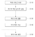
- a method for calculating a position of a GPS receiver includes a satellite signal group generation step S110, a low-error satellite signal group selection step S120, and a satellite signal detection step. (S130) and calculating position coordinates (S140). Each step may be performed by the control unit 20 of the GPS receiver 1.
- the GPS receiver 1 In the satellite signal group generation step (S110), the GPS receiver 1 generates a plurality of satellite signal groups by combining a plurality of GPS satellite signals transmitted from a plurality of GPS satellites received by the receiver 10.
- the generation rule of the plurality of satellite signal groups that is, the combination rule of the plurality of satellite signals is as follows.
- each satellite signal group may include at least four GPS satellite signals.
- each satellite signal group may include the same number of GPS satellite signals.
- k C m satellite signal groups may be generated according to a combination of m GPS satellite signals as one satellite signal group.
- m is an integer of 4 or more
- k is an integer larger than m.
- satellite signal groups having a relatively high accuracy that is, a low precision deterioration rate, may be selected from among a plurality of combinations to participate in the position calculation process described later.
- DOP dilution of precision
- Types of DOP include PDOP (Position DOP), GDOP (Geometric DOP), HDOP (Horizontal DOP), and VDOP (Vertical DOP). In this embodiment, one or more of these DOPs may be used.
- first GPS satellite signal SS1 transmitted from five GPS satellites (first GPS satellite T1 to fifth GPS satellite T5).
- the case where the fifth to fifth GPS satellite signals SS2 are received by the GPS receiver 1 will be described.
- signals received from the first GPS satellite T1 are converted into the first GPS satellite signal SS1
- signals received from the second GPS satellite T2 are converted into the second GPS satellite signal SS2
- third GPS satellites are received.
- Signals received from the T3 are received as the third GPS satellite signal SS3
- signals received from the fourth GPS satellite T4 are the fourth GPS satellite signal SS4, and received from the fifth GPS satellite T5.
- the signals may be defined as a fifth GPS satellite signal SS5.
- the control unit 20 of the GPS receiver 1 may identify the GPS satellites corresponding to the received GPS satellite signals.
- satellite signal groups G1, G2, G3, G4, and G5 may be generated as follows.
- G1 (SS2, SS3, SS4, SS5)
- G2 (SS1, SS3, SS4, SS5)
- G3 (SS1, SS2, SS4, SS5)
- G4 (SS1, SS2, SS3, SS5)
- G5 (SS1, SS2, SS3, SS4)
- the controller 20 selects the low error satellite signal group using a pseudorange of GPS satellite signals included in each satellite signal group.
- the low error satellite signal group means a satellite signal group that does not include or minimally includes a GPS satellite signal that causes reflection error.
- the pseudorange is the distance between the GPS satellites for transmitting the GPS satellite signals included in each satellite signal group and the GPS receiver 1, and uses the time taken for the GPS satellite signal to be transmitted from the GPS satellites and arrive at the GPS receiver 1. Is calculated.
- the pseudorange is calculated by multiplying the speed of the GPS satellite signal by the time taken for the GPS satellite signal to arrive (the difference between the GPS satellite signal reception time and the GPS satellite signal transmission time). This is different from the actual distance.
- pseudo-range-related variables can be calculated through location calculation method using pseudo distance by GPS satellite signals included in the satellite signal group for each satellite signal group. have.
- the pseudorange related variable may be one of, for example, an estimated position coordinate of the GPS receiver calculated using the pseudorange, a residual of the pseudorange, a correction value, a deviation of the pseudorange and the geometrical distance, and the like. Other values calculated during the normal position calculation are not excluded, and may be determined as the maximum value, the minimum value, or the average value according to the characteristics of each value.
- pseudo distance-related variables calculated for each satellite signal group using pseudo distances will be described below, taking as an example a position coordinate (latitude, longitude, altitude).
- the estimated position coordinates are calculated for each satellite signal group using pseudoranges of the GPS satellite signals included in each satellite signal group, and the satellites correspond to the predicted position coordinates separated from each other when compared with other predicted position coordinates. Select the signal group.
- the GPS satellite signals included in each satellite signal group G1 to G5 and the estimated position coordinates of the GPS receiver calculated for each satellite signal group are summarized in Table 1 below.
- the estimated position coordinates of the GPS receiver may be calculated using at least one of a least square method, a Kalman filter, and the like.
- the pseudo distance Pi between the i GPS satellite and the GPS receiver of Equation 1 and the position coordinates of the i GPS satellite A plurality of equations are generated by substituting numerical values corresponding to Xi, Yi, and Zi), respectively.
- Position coordinates (Xi, Yi, Zi) of the i-th GPS satellite are information included in the GPS satellite signal.
- Equations 2 to 6 Five equations are generated for each of the five GPS satellites as shown in Equations 2 to 6 below.
- the estimated position coordinates of the GPS receiver should be calculated for each satellite signal group.
- the estimated position coordinates (x1, y1, z1) of the GPS receiver in the first satellite signal group G1 may be calculated by the least-square method through Equations 3, 4, 5, and 6, and the second satellite signal group G2.
- the estimated position coordinates (x2, y2, z2) of the GPS receiver at) are estimated through the equations (2), (4), (5), (6), and the estimated position coordinates (x3, y3,) of the GPS receiver in the third satellite signal group (G3). z3) through Equations 2, 3, 5, and 6, and the estimated position coordinates (x4, y4, z4) of the GPS receiver in the fourth satellite signal group G4 through Equations 2, 3, 4, and 6.
- the estimated position coordinates (x5, y5, z5) of the GPS receiver in the fifth satellite signal group G5 may be calculated through Equations 2, 3, 4, and 5.
- any GPS satellite signals (illustrated as being the first satellite signal group SS1 in the drawing) are reflected by the building to the corresponding GPS satellite signals.
- the position of the GPS receiver will be calculated to be near B.
- the position of the GPS receiver is substantially the same as the position of the actual GPS receiver or only other error components except reflection errors are reflected. It is calculated as being close to A as the position.
- the estimated position coordinates (x1, y1, z1) of the first satellite signal group G1 converge in the vicinity of A, but the estimated position coordinates (x2, y2, z2) to other satellite signal groups G2 to G5- (x5, y5, z5) will be calculated to converge near C.
- the satellite signal group G1 which calculates the expected position coordinates located at different positions by more than a predetermined deviation from the estimated position coordinates of the other satellite signal groups, indicates the exact position of the actual GPS receiver.
- the satellite signal group G1, which calculates an expected position coordinate different from the other satellite signal groups does not include the GPS satellite signal SS1 causing the reflection error, and the other satellite signal groups G2, G3, and G4. , G5) may be determined to include the GPS satellite signal SS1 causing a reflection error.
- the values calculated for each satellite signal group are compared with the reference value by using pseudo distances from the GPS satellite signals included in each satellite signal group, and thus the satellites having a large difference from the reference value are calculated. Select the signal group.
- the reference value can be determined in advance experimentally and statistically.
- the satellite signal group having the predicted position coordinates having a deviation from the average coordinates of the reference value or more may be selected.
- the average coordinates (xb, yb, zb) can be calculated by Equation 7 below, and the deviation from the average coordinates (xb, yb, zb) can be found using a variance value.
- the low error phase signal group selection step (S120) when there is an expected position coordinate at which the above-described dispersion value or the like becomes equal to or more than a predetermined reference value, a reflection error exists among the GPS satellite signals used for the entire calculation. I judge that I am doing it.
- the satellite signal group having the estimated position coordinate whose deviation of the dispersion value is equal to or greater than the reference value does not exist in the satellite signal group, it is determined that the reflection error does not exist and the low error satellite signal group is selected. In this case, it may be determined that there is a reflection error, and thus the corresponding satellite signal group may not be selected.
- the first satellite signal group G1 is selected as the low error satellite signal group.
- the control unit 20 detects a GPS satellite signal that causes a reflection error in the satellite signal detection step S130.
- GPS satellite signals not included in the selected low error satellite signal group are detected as GPS satellite signals causing reflection errors.
- the first GPS satellite signal SS1 is reflected from the reflection error. Can be detected as a GPS satellite signal that causes.
- the control unit 20 calculates the position coordinates of the GPS receiver using the remaining GPS satellite signals except for the GPS satellite signal detected in the satellite signal detection step S130.
- the GPS signals other than the first GPS satellite signal SS1 detected as the GPS satellite signal including the reflection error in the satellite signal detection step S130 are detected.
- the position coordinates of the GPS receiver are calculated using the signal SS3, the fourth GPS satellite signal SS4, and the fifth GPS satellite signal SS5.
- the GPS satellite signal including the reflection error can be removed and the position coordinates of the GPS receiver can be calculated, so that the position of the GPS receiver can be determined more accurately.
- the method of removing the reflection error does not receive the reflected signal by using an antenna, and finally solves this by not including the hardware reflected signal in the calculation in the position calculation.
- the reflection error is more easily removed by not including the reflected signal in the position calculation through a software method.
- the GPS satellite signal including the reflection error is singular.
- a plurality of low error satellite signal groups are selected at one time in the satellite signal selection step S120. Can be.
- control unit 20 detects a plurality of GPS satellite signals not included in each of the plurality of selected low error satellite signal groups in the satellite signal detection step S130, and the plurality of detected GPS coordinates in the position coordinate calculation step S140.
- Position coordinates of the GPS receiver may be calculated using only the GPS satellite signals except the GPS satellite signal.
- the position calculation method of the GPS receiver according to another embodiment of the present invention may further include a position coordinate determination step S230 instead of the satellite signal detection step S130 and the position coordinate calculation step S140.
- the control unit 20 is a low error satellite signal group because the satellite signal group selected in the low error satellite signal group selection step S120 does not include a GPS satellite signal causing reflection error.
- the estimated position coordinates calculated using the satellite signal group may be determined as the position coordinates of the GPS receiver.
- k C m satellite signal groups may be generated according to a combination of m GPS satellite signals as one satellite signal group.
- m is an integer of 4 or more
- k is an integer larger than m.
- m GPS satellite signals are combined to generate a satellite signal group. If any one of the reflected satellite signals is found according to the above-described process (steps S110 to S140 or steps S110, S120 and S150), the corresponding GPS satellite signals are excluded.
- step S110 to S140 or S110, S120 and S150 may be repeated to additionally find the reflected satellite signal among the remaining GPS satellite signals.
- the GPS satellite signal having a relatively large reflection error is sequentially removed, and an operation amount can be reduced compared to other combination methods.
- pseudo-distance related variables calculated for each satellite signal group using pseudo distances are deviations of pseudo distances and geometric distances.
- the distance deviation is calculated for each satellite signal group using pseudo distances for the GPS satellite signals included in each satellite signal group, and the minimum deviation is the smallest ( Determine or detect a group of satellite signals;
- the pseudoranges, the position coordinates of the GPS satellites, and the estimated position coordinates of the GPS receiver are calculated for each satellite signal group.
- a pseudo distance P1 between the first GPS satellite T1 and the GPS receiver Pseudo-distance P2 between the second GPS satellite T2 and the GPS receiver, Pseudo-distance P3 between the third GPS satellite T3 and the GPS receiver, Pseudo-distance P4 between the fourth GPS satellite T4 and the GPS receiver is calculated.
- the position coordinates of the GPS satellites can be calculated with reference to this.
- the method of calculating the pseudorange between the GPS satellites and the GPS receiver and the position coordinates of the GPS satellites may use a known method.
- the estimated position coordinates of the GPS receiver for each satellite signal group may be calculated using the GPS satellite signals included in each satellite signal group.
- the estimated position coordinate of the GPS receiver may be calculated by the least square method, the Kalman filter, or the like.
- the difference between the pseudorange and the geometrical distance in the first satellite signal group G1 is calculated as follows.
- the first satellite signal group G1 includes the second GPS satellite signal SS2, the third GPS satellite signal SS3, the fourth GPS satellite signal SS4, and the fifth GPS satellite signal SS5, respectively.
- Four pseudo distances P2, P3, P4 and P5 between the second GPS satellite T2, the third GPS satellite T3, the fourth GPS satellite T4, the fifth GPS satellite T5 and the GPS receiver 1 ) Is calculated.
- the four position coordinates (Xi, Yi, Zi: i of the second GPS satellite T2, the third GPS satellite T3, the fourth GPS satellite T4, and the fifth GPS satellite T5) Number) is calculated.
- the estimated position coordinates x1, y1, and z1 of one GPS receiver 1 are calculated using the GPS satellite signals SS2, SS3, SS4, and SS5 included in the first satellite signal group G1.
- the geometric distance is defined as the distance between the GPS satellites transmitting the GPS satellite signals included in each satellite signal group and the estimated position coordinates calculated for each satellite signal group, where the geometric distance is the position coordinates (Xi, Yi, Zi: the position coordinate of the i-th GPS satellite) and the estimated position coordinates (x1, y1, z1) of the GPS receiver 1.
- Equation 8 the deviation (A) of the pseudorange and the geometrical distance
- the first satellite signal group G1 includes four GPS satellite signals, four deviations A of pseudorange and geometric distance are also calculated.
- each of the four pseudo-range and the geometric distance will be calculated.
- the maximum or average value may be taken as a representative value, or the sum of squared differences and the like may be taken as a representative value.
- the most representative of the distance deviation representative values calculated for each satellite signal group (representative values using deviations of at least four pseudoranges and geometric distances calculated from any satellite signal group) A satellite signal group having a small value is selected as a low error satellite signal group.
- the accuracy concept is related to the precision degradation rate such as DOP.
- the accuracy of the calculation result is obtained by adding the squared and normalized difference between the geometric distance (theoretical value) and the pseudo distance (measured value) of each GPS satellite included in the calculation.
- the accuracy of the satellite signal group having a large amount of space between the GPS satellites transmitting the GPS satellite signals belonging to the satellite signal group has the smallest value.
- the representative value of the distance deviation in the present embodiment is also similar to DOP, indicating a position error, because the GPS satellite signal causing reflection error does not exist in the satellite signal group having the smallest value. to be.
- the satellite signal group having the farthest value when compared with the calculated values of other satellite signal groups is a satellite signal group that does not include a reflection error.
- the distance deviation representative value of the satellite signal group including the reflection error has the minimum value.
- the subsequent steps are the same as described above, and the description thereof is omitted here.
- the position calculation method of the GPS receiver may be implemented as a program and stored in a computer-readable recording medium.
- the recording medium may be, for example, an electronic, magnetic, optical, electromagnetic, infrared, or semiconductor system, apparatus, device, or propagation medium, but is not limited thereto. More specific examples of the recording medium may include a computer diskette ( Magnetic), random access memory (RAM) (electronic), read-only memory (ROM) (electronic), erasable programmable read-only memory (EPROM, EEPROM, or flash memory) (electronic), optical fiber (optical), DVD ( optical media such as digital versatile discs or compact disc read-only memory.
- the computer readable recording medium can also be distributed over network coupled computer systems so that the computer readable code is stored and executed in a distributed fashion.
- the program may be paper or other suitable media on which the program is printed, because the program may be captured electronically through optical scanning of paper or other media, then compiled as needed, Because it can be interpreted or processed in an appropriate manner and then stored in computer memory.
- FIG. 5 is a block diagram illustrating a schematic configuration of a controller of a GPS receiver according to an embodiment of the present invention.
- the GPS receiver 1 includes a combiner 22, a satellite signal group selector 24, a satellite signal detector 26, and a position calculator 28.
- the combiner 22 generates a plurality of satellite signal groups by combining the plurality of GPS satellite signals received by the receiver 10. That is, the combiner 22 performs the above-described satellite signal group generation step (S110).
- the satellite signal group selector 24 selects a low error satellite signal group having no or minimal reflection error by using a pseudo distance by GPS satellite signals included in each satellite signal group generated by the combiner 22. Select. That is, the satellite signal group selector 24 performs the low error satellite signal group selection step (S120) described above.
- the satellite signal detection unit 26 reflects a GPS satellite signal other than a plurality of GPS satellite signals included in the low error satellite signal group selected by the satellite signal group selector 24, which is a GPS satellite signal including a reflection error. Detect by signal.
- the satellite signal detector 26 performs the above-described satellite signal detection step S130.
- the position calculator 28 calculates the position coordinates of the GPS receiver using the remaining GPS satellite signals except for the GPS satellite signal detected as having a reflection error by the satellite signal detector 26. That is, the position calculating unit 28 performs the above-described position coordinate calculation step (S140).
- the position calculating unit 28 converts the estimated position coordinate into the position coordinate of the GPS receiver. You can decide.
- control unit 22 such as a central processing unit (CPU) ( Of course it can be implemented as 20).
- CPU central processing unit
Landscapes
- Engineering & Computer Science (AREA)
- Radar, Positioning & Navigation (AREA)
- Remote Sensing (AREA)
- Computer Networks & Wireless Communication (AREA)
- Physics & Mathematics (AREA)
- General Physics & Mathematics (AREA)
- Computer Security & Cryptography (AREA)
- Position Fixing By Use Of Radio Waves (AREA)
Abstract
GPS 수신기의 위치 계산 방법, 그 방법을 구현하기 위한 프로그램이 기록된 기록매체 및 GPS 수신기가 개시된다. 일 실시예에 따른 GPS 수신기의 위치 계산 방법은, 제어부에서 수신부를 통해 수신된 복수의 GPS 위성 신호를 조합하여 복수의 위성 신호군을 생성하는 단계, 각 위성 신호군에 포함된 GPS 위성 신호들에 의한 의사거리를 이용하여 반사 오차를 야기하는 GPS 위성 신호를 포함하지 않거나 최소로 포함하는 저오차 위성 신호군을 선별하는 단계, 상기 저오차 위성 신호군에 포함되지 않는 GPS 위성 신호를 반사 위성 신호로 검출하는 단계 및 상기 반사 위성 신호를 제외한 나머지 GPS 위성 신호를 이용하여 상기 GPS 수신기의 위치 좌표를 산출하는 단계를 포함한다. 이에 의하면, 반사 오차를 야기하는 GPS 위성을 위치 계산에서 제외함으로써 반사 오차를 제거하여 현재 GPS 수신기의 위치를 보다 정확하게 산출할 수 있는 효과가 있다.
Description
본 발명은 GPS 수신기의 위치 계산 방법, 그 방법을 구현하기 위한 프로그램이 기록된 기록매체 및 GPS 수신기에 관한 것이다.
GPS(Global Positioning System)는 21세기 고도 정보화 사회에서 전자시스템 및 멀티미디어의 급속한 보급에 따라 더욱 중요시 되고 있는 산업이며, 전기, 전자, 통신 등 다양한 기술의 융합을 통하여 구현할 수 있는 통합 기술 분야이다. 현재 GPS 기술은 자동차항법장치 등에 쓰이는 위치측정시스템으로 주로 활용되고 있으며, 관련산업 및 시장은 지속적으로 확대되고 있다.
한편, 전파를 이용한 항법 방식인 GPS의 위성 신호에는 전리층 지연(ionospheric delay), 대류권 지연(tropospheric delay), 수신기 시계 바이어스(receiver clock bias), 열잡음(thermal noise), 반사(reflection) 등과 같은 다양한 오차성분이 포함된다.
위성 신호에 포함된 오차성분에 의한 영향을 최소화하여 위치 오차를 보정하고 측위 정확도를 높이기 위해 상대 측위 방식인 DGPS(Differential Global Positioning System)가 이용된다. 한국공개특허 2011-0041211호를 참조하면, DGPS를 이용하여 위치 오차를 보정하여 위치 해상도를 높이는 GPS 모듈 및 이를 이용한 DGPS 수신 장치가 개시되어 있다.
전리층 지연, 대류권 지연, 수신기 시계 바이어스, 열잡음에 의한 오차성분들은 DGPS에 의해 그 영향이 상당히 감소될 수 있다. 하지만, 반사에 의한 오차(이하, 반사 오차)의 경우 앞서 열거된 오차 요인들과는 그 특성이 상이하여 종래의 DGPS와 같은 기법으로는 반사 오차를 제거할 수 없었다.
도 1은 반사 오차의 발생 과정을 나타낸 도면이다.
도 1을 참조하면, 반사 오차는 인공위성에서 송신된 위성 신호가 주변 건물이나 지표면에 반사된 후 GPS 수신기(1)에 입력됨으로써 발생되는 위치 오차이다.
특히나 높은 건물이 많은 도심에서는 GPS 위성 신호는 건물을 통과하지 못한다. 그리고 도로와 같이 양쪽에 건물이 늘어서 있는 경우, 양쪽 방향에서 GPS 위성 신호를 수신한 것과 같이 보이지만 실제로는 반대편의 건물에서 반사된 GPS 위성 신호가 수신된 것일 수 있다.
또한, 건물에서 반사된 GPS 위성 신호의 강도는 반사되지 않은 GPS 위성 신호와 거의 구별할 수 없는데, 이는 반사된 GPS 위성 신호의 강도가 이론적으로는 작아져야 하나, GPS 위성의 거리가 배치에 따라 다르고, 거리가 먼 GPS 위성으로부터 GPS 위성 신호는 신호강도가 작기 때문이다.
반사 오차는 높은 건물 및 넓은 도로가 존재하는 큰 도시일수록 더 크게 되고, 통상적으로 도로 폭에 상응하는 오차를 가지게 된다. 또한 반사 오차의 발생위치나 시간 및 오차의 크기를 예측할 수 없는 문제가 있다.
이러한 반사 오차를 제거할 필요가 있으며, 반사 오차를 제거하는 방법으로는 적응형 안테나 어레이(Adaptive Antenna Array) 방법 등이 있으나, 다수의 안테나를 사용해야 한다는 점 등으로 모바일 기기에서 그 적용이 어렵다는 문제점이 있었다.
전술한 배경기술은 발명자가 본 발명의 도출을 위해 보유하고 있었거나, 본 발명의 도출 과정에서 습득한 기술 정보로서, 반드시 본 발명의 출원 전에 일반 공중에게 공개된 공지기술이라 할 수는 없다.
본 발명은, 반사 오차를 야기하는 GPS 위성을 위치 계산에서 제외함으로써 반사 오차를 제거하여 현재 GPS 수신기의 위치를 보다 정확하게 산출할 수 있는 GPS 수신기의 위치 계산 방법, 그 방법을 구현하기 위한 프로그램이 기록된 기록매체 및 GPS 수신기를 제공하기 위한 것이다.
또한, 본 발명은 GPS 위성들을 복수의 위성 신호군으로 조합하고, 각 위성군별 위치 좌표 중 반사 오차를 포함하지 않은 위치 좌표를 찾음으로써, 정확한 GPS 수신기의 위치를 측정할 수 있는 GPS 수신기의 위치 계산 방법, 그 방법을 구현하기 위한 프로그램이 기록된 기록매체 및 GPS 수신기를 제공하기 위한 것이다.
본 발명의 이외의 목적들은 하기의 설명을 통해 쉽게 이해될 수 있을 것이다.
본 발명의 일 측면에 따르면, GPS 수신기의 위치를 계산하는 방법 및 이를 수행하기 위한 프로그램이 기록된 기록매체가 제공된다.
일 실시예에 따른 GPS 수신기의 위치 계산 방법은, 제어부에서 수신부를 통해 수신된 복수의 GPS 위성 신호를 조합하여 복수의 위성 신호군을 생성하는 단계, 각 위성 신호군에 포함된 GPS 위성 신호들에 의한 의사거리(Pseudorange)를 이용하여 반사 오차를 야기하는 GPS 위성 신호를 포함하지 않거나 최소로 포함하는 저오차 위성 신호군을 선별하는 단계, 상기 저오차 위성 신호군에 포함되지 않는 GPS 위성 신호를 반사 위성 신호로 검출하는 단계 및 상기 반사 위성 신호를 제외한 나머지 GPS 위성 신호를 이용하여 상기 GPS 수신기의 위치 좌표를 산출하는 단계를 포함한다.
상기 복수의 위성 신호군을 생성하는 단계는 k개의 GPS 위성 신호가 수신되는 경우 m개씩의 GPS 위성 신호를 하나의 위성 신호군으로 하는 조합에 따라 kCm개의 위성 신호군을 생성하되, m은 4 이상의 정수이고, k는 m보다 큰 정수일 수 있다.
상기 복수의 위성 신호군을 생성하는 단계는 상대적으로 DOP(Dilution of Precision)가 낮은 위성 신호군들이 생성되도록 상기 복수의 GPS 위성 신호를 조합할 수 있다.
상기 저오차 위성 신호군을 선별하는 단계는 상기 의사거리를 이용하여 계산된 상기 GPS 수신기의 예상 위치 좌표, 상기 의사거리의 잔차(residual), 보정값, 상기 의사거리와 기하학적 거리의 편차 중 적어도 하나를 포함하는 의사거리 관련 변수를 계산한 결과에 기초하여 상기 저오차 위성 신호군을 선별할 수 있다.
상기 의사거리 관련 변수가 상기 예상 위치 좌표인 경우, 상기 저오차 위성 신호군을 선별하는 단계는 상기 각 위성 신호군에 포함된 GPS 위성 신호들에 의한 의사거리를 이용하여 상기 각 위성 신호군 별로 예상 위치 좌표를 계산하고, 다른 예상 위치 좌표와 비교할 때 동떨어진 예상 위치 좌표에 상응하는 위성 신호군을 상기 저오차 위성 신호군으로 선별할 수 있다.
상기 저오차 위성 신호군을 선별하는 단계는 상기 각 위성 신호군 별 예상 위치 좌표의 평균 좌표를 계산하고, 상기 평균 좌표와의 편차가 기준값 이상인 예상 위치 좌표를 갖는 위성 신호군을 상기 저오차 위성 신호군으로 선별할 수 있다.
상기 의사거리 관련 변수가 상기 의사거리와 기하학적 거리의 편차인 경우, 상기 저오차 위성 신호군을 선별하는 단계는 상기 각 위성 신호군 별로 상기 위성 신호군에 포함되는 상기 GPS 위성 신호 별 거리 편차의 대표값을 계산하고, 상기 거리 편차의 대표값이 최소인 위성 신호군을 저오차 위성 신호군으로 선별할 수 있다.
반사 오차를 포함하는 GPS 위성 신호가 복수인 경우, 상기 저오차 위성 신호군을 선별하는 단계는 한번에 복수의 저오차 위성 신호군을 선별하며, 상기 반사 위성 신호로 검출하는 단계는 상기 복수의 저오차 위성 신호군 각각에 포함되지 않은 복수의 GPS 위성 신호를 반사 위성 신호로 검출할 수 있다.
다른 실시예에 따른 GPS 수신기의 위치 계산 방법은, 제어부에서 수신부를 통해 수신된 복수의 GPS 위성 신호를 조합하여 복수의 위성 신호군을 생성하는 단계, 각 위성 신호군에 포함된 GPS 위성 신호들에 의한 의사거리를 이용하여 반사 오차를 야기하는 GPS 위성 신호를 포함하지 않는 저오차 위성 신호군을 선별하는 단계 및 상기 저오차 위성 신호군에서 계산된 예상 위치 좌표를 상기 GPS 수신기의 위치 좌표를 산출하는 단계를 포함한다.
상기 저오차 위성 신호군을 선별하는 단계는 상기 각 위성 신호군에 포함된 GPS 위성 신호들에 의한 의사거리를 이용하여 상기 각 위성 신호군 별로 예상 위치 좌표를 계산하고, 다른 예상 위치 좌표와 비교할 때 동떨어진 예상 위치 좌표에 상응하는 위성 신호군을 상기 저오차 위성 신호군으로 선별할 수 있다.
상기 저오차 위성 신호군을 선별하는 단계는 상기 각 위성 신호군 별 예상 위치 좌표의 평균 좌표를 계산하고, 상기 평균 좌표와의 편차가 기준값 이상인 예상 위치 좌표를 갖는 위성 신호군을 상기 저오차 위성 신호군으로 선별할 수 있다.
한편 본 발명의 다른 측면에 따르면, 수신부를 통해 수신된 복수의 GPS 위성 신호를 조합하여 복수의 위성 신호군을 생성하는 조합부, 각 위성 신호군에 포함된 GPS 위성 신호들에 의한 의사거리를 이용하여 반사 오차를 야기하는 GPS 위성 신호를 포함하지 않거나 최소로 포함하는 저오차 위성 신호군을 선별하는 위성 신호군 선별부, 상기 저오차 위성 신호군에 포함되지 않는 GPS 위성 신호를 반사 위성 신호로 검출하는 위성 신호 검출부 및 상기 반사 위성 신호를 제외한 나머지 GPS 위성 신호를 이용하여 상기 GPS 수신기의 위치 좌표를 산출하는 위치 연산부를 포함하는 GPS 수신기가 제공된다.
상기 조합부는 k개의 GPS 위성 신호가 수신되는 경우 m개씩의 GPS 위성 신호를 하나의 위성 신호군으로 하는 조합에 따라 kCm개의 위성 신호군을 생성하되, m은 4 이상의 정수이고, k는 m보다 큰 정수일 수 있다.
상기 조합부는 상대적으로 DOP가 낮은 위성 신호군들이 생성되도록 상기 복수의 GPS 위성 신호를 조합할 수 있다.
상기 위성 신호군 선별부는 상기 의사거리를 이용하여 계산된 상기 GPS 수신기의 예상 위치 좌표, 상기 의사거리의 잔차, 보정값, 상기 의사거리와 기하학적 거리의 편차 중 적어도 하나를 포함하는 의사거리 관련 변수를 계산한 결과에 기초하여 상기 저오차 위성 신호군을 선별할 수 있다.
상기 의사거리 관련 변수가 상기 예상 위치 좌표인 경우, 상기 위성 신호군 선별부는 상기 각 위성 신호군에 포함된 GPS 위성 신호들에 의한 의사거리를 이용하여 상기 각 위성 신호군 별로 예상 위치 좌표를 계산하고, 다른 예상 위치 좌표와 비교할 때 동떨어진 예상 위치 좌표에 상응하는 위성 신호군을 상기 저오차 위성 신호군으로 선별할 수 있다.
상기 위성 신호군 선별부는 상기 각 위성 신호군 별 예상 위치 좌표의 평균 좌표를 계산하고, 상기 평균 좌표와의 편차가 기준값 이상인 예상 위치 좌표를 갖는 위성 신호군을 상기 저오차 위성 신호군으로 선별할 수 있다.
상기 의사거리 관련 변수가 상기 의사거리와 기하학적 거리의 편차인 경우, 상기 위성 신호군 선별부는 상기 각 위성 신호군 별로 상기 위성 신호군에 포함되는 상기 GPS 위성 신호 별 거리 편차의 대표값을 계산하고, 상기 거리 편차의 대표값이 최소인 위성 신호군을 저오차 위성 신호군으로 선별할 수 있다.
반사 오차를 포함하는 GPS 위성 신호가 복수인 경우, 상기 위성 신호군 선별부는 한번에 복수의 저오차 위성 신호군을 선별하며, 상기 위성 신호 검출부는 상기 복수의 저오차 위성 신호군 각각에 포함되지 않은 복수의 GPS 위성 신호를 반사 위성 신호로 검출할 수 있다.
한편 본 발명의 또 다른 측면에 따르면, 수신부를 통해 수신된 복수의 GPS 위성 신호를 조합하여 복수의 위성 신호군을 생성하는 조합부, 각 위성 신호군에 포함된 GPS 위성 신호들에 의한 의사거리를 이용하여 반사 오차를 야기하는 GPS 위성 신호를 포함하지 않는 저오차 위성 신호군을 선별하는 위성 신호군 선별부 및 상기 저오차 위성 신호군에서 계산된 예상 위치 좌표를 상기 GPS 수신기의 위치 좌표를 산출하는 위치 연산부를 포함하는 GPS 수신기가 제공된다.
상기 위성 신호군 선별부는 상기 각 위성 신호군에 포함된 GPS 위성 신호들에 의한 의사거리를 이용하여 상기 각 위성 신호군 별로 예상 위치 좌표를 계산하고, 다른 예상 위치 좌표와 비교할 때 동떨어진 예상 위치 좌표에 상응하는 위성 신호군을 상기 저오차 위성 신호군으로 선별할 수 있다.
상기 위성 신호군 선별부는 상기 각 위성 신호군 별 예상 위치 좌표의 평균 좌표를 계산하고, 상기 평균 좌표와의 편차가 기준값 이상인 예상 위치 좌표를 갖는 위성 신호군을 상기 저오차 위성 신호군으로 선별할 수 있다.
전술한 것 외의 다른 측면, 특징, 이점이 이하의 도면, 특허청구범위 및 발명의 상세한 설명으로부터 명확해질 것이다.
본 발명의 바람직한 실시예에 따르면, 반사 오차를 야기하는 GPS 위성을 위치 계산에서 제외함으로써 반사 오차를 제거하여 현재 GPS 수신기의 위치를 보다 정확하게 산출할 수 있는 효과가 있다.
또한, GPS 위성들을 복수의 위성 신호군으로 조합하고, 각 위성군별 위치 좌표 중 반사 오차를 포함하지 않은 위치 좌표를 찾음으로써, 정확한 GPS 수신기의 위치를 측정할 수 있는 효과가 있다.
도 1은 반사 오차의 발생 과정을 나타낸 도면,
도 2는 본 발명의 일 실시예에 따른 GPS 수신기를 나타낸 도면,
도 3은 본 발명의 일 실시예에 따른 GPS 수신기의 위치 계산 방법을 나타낸 순서도,
도 4는 반사 오차에 따른 위치 계산의 오류를 설명하기 위한 도면,
도 5는 본 발명의 일 실시예에 따른 GPS 수신기의 제어부의 개략적인 구성을 나타낸 블록도.
본 발명은 다양한 변환을 가할 수 있고 여러 가지 실시예를 가질 수 있는 바, 특정 실시예들을 도면에 예시하고 상세한 설명에 상세하게 설명하고자 한다. 그러나, 이는 본 발명을 특정한 실시 형태에 대해 한정하려는 것이 아니며, 본 발명의 사상 및 기술 범위에 포함되는 모든 변환, 균등물 내지 대체물을 포함하는 것으로 이해되어야 한다. 본 발명을 설명함에 있어서 관련된 공지 기술에 대한 구체적인 설명이 본 발명의 요지를 흐릴 수 있다고 판단되는 경우 그 상세한 설명을 생략한다.
제1, 제2 등의 용어는 다양한 구성요소들을 설명하는데 사용될 수 있지만, 상기 구성요소들은 상기 용어들에 의해 한정되어서는 안 된다. 상기 용어들은 하나의 구성요소를 다른 구성요소로부터 구별하는 목적으로만 사용된다.
본 출원에서 사용한 용어는 단지 특정한 실시예를 설명하기 위해 사용된 것으로, 본 발명을 한정하려는 의도가 아니다. 단수의 표현은 문맥상 명백하게 다르게 뜻하지 않는 한, 복수의 표현을 포함한다. 본 출원에서, "포함하다" 또는 "가지다" 등의 용어는 명세서상에 기재된 특징, 숫자, 단계, 동작, 구성요소, 부품 또는 이들을 조합한 것이 존재함을 지정하려는 것이지, 하나 또는 그 이상의 다른 특징들이나 숫자, 단계, 동작, 구성요소, 부품 또는 이들을 조합한 것들의 존재 또는 부가 가능성을 미리 배제하지 않는 것으로 이해되어야 한다.
또한, 명세서에 기재된 "…부" 등의 용어는 적어도 하나의 기능이나 동작을 처리하는 단위를 의미하며, 이는 하드웨어나 소프트웨어 또는 하드웨어 및 소프트웨어의 결합으로 구현될 수 있다.
이하, 본 발명의 실시예를 첨부한 도면들을 참조하여 상세히 설명하기로 하며, 첨부 도면을 참조하여 설명함에 있어, 동일하거나 대응하는 구성 요소는 동일한 도면번호를 부여하고 이에 대한 중복되는 설명은 생략하기로 한다.
도 2는 본 발명의 일 실시예에 따른 GPS 수신기를 나타낸 도면이다.
도 2를 참조하면, GPS 수신기(1)는 수신부(10)와 제어부(20)를 포함한다.
수신부(10)는 복수의 GPS 위성들(T1~T5)로부터 송출되는 GPS 위성 신호들(SS1~SS5)을 수신하고, 수신된 GPS 위성 신호들을 제어부(20)로 전달한다.
제어부(20)는 수신부(10)로부터 전달된 GPS 위성 신호들을 이용하여, GPS 수신기(1)의 위치 좌표를 산출한다. 특히 제어부(20)는 반사 오차를 제거하여 GPS 수신기(1)의 정확한 위치 좌표를 산출하기 위해 이하 실시예에 따른 위치 계산 방법을 수행한다.
도 3은 본 발명의 일 실시예에 따른 GPS 수신기의 위치 계산 방법을 나타낸 순서도이고, 도 4는 반사 오차에 따른 위치 계산의 오류를 설명하기 위한 도면이다.
본 발명의 일 실시예에 따른 GPS 수신기의 위치 계산 방법은 수신부(10)를 통해 수신된 GPS 위성 신호들 중에서 반사 오차를 포함하는 GPS 위성 신호를 검출하고 반사 오차를 포함하는 GPS 위성 신호(이하 '반사 위성 신호'라 칭함)는 GPS 수신기의 위치 계산에 참여시키지 않음으로써, 반사 오차를 제거할 수 있어 GPS 수신기의 위치를 보다 정확하게 산출할 수 있다.
도 3을 참조하면, 본 발명의 일 실시예에 따른 GPS 수신기의 위치 계산 방법은 위성 신호군 생성 단계(S110), 저오차(low-error) 위성 신호군 선별 단계(S120), 위성 신호 검출 단계(S130) 및 위치 좌표 산출 단계(S140)를 포함한다. 각 단계는 GPS 수신기(1)의 제어부(20)에서 수행될 수 있다.
위성 신호군 생성 단계(S110)에서 GPS 수신기(1)는 수신부(10)에서 수신한 복수의 GPS 위성으로부터 송출된 복수의 GPS 위성 신호를 조합하여 복수의 위성 신호군을 생성한다.
복수의 위성 신호군의 생성 규칙, 즉 복수의 위성 신호의 조합 규칙은 다음과 같다.
우선 GPS 수신기(1)의 위치 좌표를 계산하기 위해서는 적어도 4개 이상의 GPS 위성 신호가 필요하므로, 각 위성 신호군에는 적어도 4개의 GPS 위성 신호가 포함될 수 있다.
또한, 각 위성 신호군에는 동일한 개수의 GPS 위성 신호들이 포함될 수 있다.
예를 들어, k개의 GPS 위성 신호가 수신되는 경우 m개씩의 GPS 위성 신호를 하나의 위성 신호군으로 하는 조합에 따라 kCm개의 위성 신호군을 생성할 수 있다. 이 때, m은 4 이상의 정수이고, k는 m보다 큰 정수이다.
여기서 위성 신호군을 생성할 때, 그 조합의 수가 너무 많은 경우 모든 조합에 대한 계산을 하는 것은 많은 연산량이 필요하고 계산 시간이 지체되는 문제점이 있을 수 있다. 이 경우에는 다수의 조합 중에서 상대적으로 정확도가 높은, 즉 정밀도 저하율이 낮은 위성 신호군들만을 선택하여 후술하는 위치 계산 과정에 참여시킬 수 있다.
위성 배치에 따른 정확도는 예를 들어 DOP(Dilution of Precision) 등과 같은 정밀도 저하율을 통해 확인할 수 있다. DOP는 GPS 위성들의 상대적인 기하학이 GPS 수신기의 위치 결정에 미치는 오차를 나타내는 무차원의 수이다. 위성들 간의 공간이 더 많으면 많을수록 GPS 수신기에서 결정하는 위치 정밀도가 높아지게 되는데, DOP가 작은 값을 가질수록 GPS 위성이 고른 배열을 가지고 있어 위치 계산의 정확성이 높아진다.
DOP의 종류로는 PDOP(Position DOP), GDOP(Geometric DOP), HDOP(Horizontal DOP), VDOP(Vertical DOP) 등이 있으며, 본 실시예에서는 이 중 하나 이상의 DOP가 이용될 수 있다.
즉, 위성 신호군 생성 단계(S110)에서 상대적으로 DOP가 낮은 위성 신호군들이 생성되도록 GPS 위성 신호들을 조합함으로써, 모든 위성 신호군 생성 조합에 대한 계산을 할 필요가 없어 계산량 및 계산시간을 감소시킬 수 있게 된다.
이하에서는, 도 2에 예시된 것과 같이, 5개의 GPS 위성(제1 GPS 위성(T1) 내지 제5 GPS 위성(T5))으로부터 송출된 5개의 GPS 위성 신호들(제1 GPS 위성 신호(SS1) 내지 제5 GPS 위성 신호(SS2))이 GPS 수신기(1)에 수신된 경우를 가정하여 설명하기로 한다.
여기서, 제1 GPS 위성(T1)으로부터 수신되는 신호들을 제1 GPS 위성 신호(SS1)로, 제2 GPS 위성(T2)으로부터 수신되는 신호들을 제2 GPS 위성 신호(SS2)로, 제3 GPS 위성(T3)으로부터 수신되는 신호들을 제3 GPS 위성 신호(SS3)로, 제4 GPS 위성(T4)으로부터 수신되는 신호들을 제4 GPS 위성 신호(SS4)로, 제5 GPS 위성(T5)으로부터 수신되는 신호들을 제5 GPS 위성 신호(SS5)로 정의할 수 있다.
GPS 위성 신호는 송출된 GPS 위성의 식별정보(ID)를 포함하고 있기 때문에, GPS 수신기(1)의 제어부(20)는 수신된 각 GPS 위성 신호에 대응하는 GPS 위성을 식별할 수 있다.
5개의 GPS 위성 신호들 중 임의의 4개를 선택하여 조합하는 경우, 5(=5C4)개의 위성 신호군(G1, G2, G3, G4, G5)이 다음과 같이 생성될 수 있다.
G1 (SS2, SS3, SS4, SS5)
G2 (SS1, SS3, SS4, SS5)
G3 (SS1, SS2, SS4, SS5)
G4 (SS1, SS2, SS3, SS5)
G5 (SS1, SS2, SS3, SS4)
저오차 위성 신호군 선별 단계(S120)에서 제어부(20)는 각 위성 신호군에 포함된 GPS 위성 신호들에 의한 의사거리(Pseudorange)를 이용하여 저오차 위성 신호군을 선별한다. 여기서, 저오차 위성 신호군은 반사 오차를 야기하는 GPS 위성 신호를 포함하지 않거나 최소로 포함하는 위성 신호군을 의미한다.
의사거리는 각 위성 신호군에 포함된 GPS 위성 신호들을 송출하는 GPS 위성들과 GPS 수신기(1) 사이의 거리로서, GPS 위성 신호가 GPS 위성으로부터 송출되어 GPS 수신기(1)에 도착하는데 걸린 시간을 이용하여 산출된다.
즉, 의사거리는 GPS 위성 신호의 속도 및 GPS 위성 신호가 도착하는데 걸린 시간(GPS 위성 신호 수신시각과 GPS 위성 신호 송신시각 간의 차)을 곱한 값으로 계산되며, 이는 여러 오차 요인들을 포함하고 있는 점에서 실제 거리와는 차이가 있다.
의사거리를 이용하여 저오차 위성 신호군을 선별하기 위해, 각 위성 신호군별로 해당 위성 신호군에 포함된 GPS 위성 신호들에 의한 의사거리를 활용한 위치 계산 방식을 통해 의사거리 관련 변수를 계산할 수 있다.
의사거리 관련 변수는 예를 들어 의사거리를 이용하여 계산된 GPS 수신기의 예상 위치 좌표, 의사거리의 잔차(residual), 보정값, 의사거리와 기하학적 거리의 편차 등 중 하나일 수 있다. 그 외 통상의 위치 계산 중에 산출되는 다른 값들을 배제하지는 않으며, 각 값의 특성에 따라 최대값, 최소값, 평균값 등으로 판단할 수 있다.
그 중 의사거리를 이용하여 각 위성 신호군 별로 계산된 의사거리 관련 변수가 위치 좌표(위도, 경도, 고도)인 경우를 예로 들어 이하 살펴보도록 한다.
일 실시예에서, 각 위성 신호군에 포함된 GPS 위성 신호들에 의한 의사거리를 이용하여 각 위성 신호군 별로 예상 위치 좌표를 계산하고, 다른 예상 위치 좌표와 비교할 때 동떨어진 예상 위치 좌표에 상응하는 위성 신호군을 선별한다.
각 위성 신호군(G1~G5)에 포함된 GPS 위성 신호와 각 위성 신호군별로 산출된 GPS 수신기의 예상 위치 좌표를 정리하면, 아래 표 1과 같다.
[규칙 제26조에 의한 보정 09.04.2012]
표 1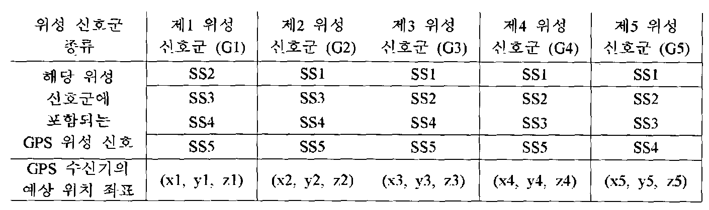
표 1
이 때 GPS 수신기의 예상 위치 좌표는 최소자승법(Least Square Method), 칼만 필터 등 중 적어도 하나의 방법으로 계산될 수 있다.
예를 들어, 최소자승법과 하기의 수학식 1을 기반으로 하여 각 위성 신호군 별 GPS 수신기의 위치 좌표를 구하는 과정을 설명한다. 편의상 이온층 등의 보정항 등은 생략한다.
[규칙 제26조에 의한 보정 09.04.2012]
수학식 1
수학식 1
수학식 1에 존재하는 미지수인 GPS 수신기의 위치 좌표 (Xgps, Ygps, Zgps)를 구하기 위하여, 수학식 1의 제i GPS 위성과 GPS 수신기 간의 의사거리(Pi) 및 제i GPS 위성의 위치 좌표 (Xi, Yi, Zi)에 각각 대응되는 수치를 대입하여 복수개의 방정식을 생성한다. 제i GPS 위성의 위치 좌표 (Xi, Yi, Zi)는 GPS 위성 신호에 포함되어 있는 정보이다.
상술한 예를 적용하면 5개의 GPS 위성 각각에 대하여 하기 수학식 2 내지 수학식 6과 같이 5개의 방정식이 생성된다.
[규칙 제26조에 의한 보정 09.04.2012]
수학식 2
수학식 2
[규칙 제26조에 의한 보정 09.04.2012]
수학식 3
수학식 3
[규칙 제26조에 의한 보정 09.04.2012]
수학식 4
수학식 4
[규칙 제26조에 의한 보정 09.04.2012]
수학식 5
수학식 5
[규칙 제26조에 의한 보정 09.04.2012]
수학식 6
수학식 6
그 후 각 위성 신호군별로 GPS 수신기의 예상 위치 좌표를 산출해야 한다.
제1 위성 신호군(G1)에서의 GPS 수신기의 예상 위치 좌표 (x1, y1, z1)는 수학식 3, 4, 5, 6을 통한 최소자승법으로 산출될 수 있으며, 제2 위성 신호군(G2)에서의 GPS 수신기의 예상 위치 좌표 (x2, y2, z2)는 수학식 2, 4, 5, 6을 통해, 제3 위성 신호군(G3)에서의 GPS 수신기의 예상 위치 좌표 (x3, y3, z3)는 수학식 2, 3, 5, 6을 통해, 제4 위성 신호군(G4)에서의 GPS 수신기의 예상 위치 좌표 (x4, y4, z4)는 수학식 2, 3, 4, 6을 통해, 제5 위성 신호군(G5)에서의 GPS 수신기의 예상 위치 좌표 (x5, y5, z5)는 수학식 2, 3, 4, 5를 통해 산출될 수 있다.
도 4를 참조하면, 실제 GPS 수신기의 위치가 A일 때, 임의의 GPS 위성 신호(도면에서는 제1 위성 신호군(SS1)인 것으로 예시되어 있음)가 건물에 의해 반사되는 경우 해당 GPS 위성 신호에 의한 GPS 수신기의 위치는 B 근방인 것으로 계산될 것이다.
반사 오차를 야기하는 제1 GPS 위성 신호(SS1)를 포함하는 위성 신호군들(G2, G3, G4, G5)에서는 GPS 수신기의 예상 위치 좌표를 산출하면 평균적으로 그 위치가 C 근방에 수렴하는 것으로 계산하게 된다.
하지만, 제1 GPS 위성 신호(SS1)를 포함하지 않는 위성 신호군(G1)에서는 GPS 수신기의 예상 위치 좌표를 산출하면 실제 GPS 수신기의 위치와 실질적으로 동일하거나 반사 오차를 제외한 기타 오차성분만이 반영된 위치로서 A에 근접한 것으로 계산하게 된다.
즉, 제1 위성 신호군(G1)의 예상 위치 좌표 (x1, y1, z1)는 A 근방에 수렴하지만, 다른 위성 신호군들(G2~G5)의 예상 위치 좌표 (x2, y2, z2) ~ (x5, y5, z5)는 C 근방에 수렴하는 것으로 계산될 것이다.
따라서, 다른 위성 신호군들의 예상 위치 좌표와는 소정의 편차 이상으로 다른 위치에 위치하는 예상 위치 좌표를 산출하게 되는 위성 신호군(G1)이 실제 GPS 수신기의 정확한 위치를 나타내게 된다. 이를 통해 다른 위성 신호군들과는 다른 예상 위치 좌표를 산출하게 되는 위성 신호군(G1)이 반사 오차를 야기하는 GPS 위성 신호(SS1)를 포함하고 있지 아니하며, 다른 위성 신호군들(G2, G3, G4, G5)은 반사 오차를 야기하는 GPS 위성 신호(SS1)를 포함하고 있는 것으로 판단할 수 있다.
보다 상세하게는, 각 위성 신호군에 포함된 GPS 위성 신호들에 의한 의사거리를 이용하여 각 위성 신호군 별로 계산된 값들을 기준값과 비교하고, 이를 통해 기준값과의 차이가 큰 계산값을 갖는 위성 신호군을 선별한다. 여기서, 기준값은 실험적, 통계적으로 결정되어 미리 설정될 수 있음은 자명하다.
전술한 실시예에서 각 위성 신호군 별 예상 위치 좌표에 대한 평균 좌표를 계산한 후, 평균 좌표와의 편차가 기준값 이상인 예상 위치 좌표를 갖는 위성 신호군을 선별할 수 있다.
이 경우 평균 좌표 (xb, yb, zb)는 하기 수학식 7에 의해 계산될 수 있으며, 평균 좌표 (xb, yb, zb)와의 편차는 분산값 등을 이용해 알아낼 수 있다.
[규칙 제26조에 의한 보정 09.04.2012]
수학식 7
수학식 7
따라서, 저오차 위상 신호군 선별 단계(S120)에서는 전술한 분산값 등이 기 설정된 소정의 기준값 이상이 되는 예상 위치 좌표가 존재하는 경우에, 전체 계산에 이용된 GPS 위성 신호들 중에서 반사 오차가 존재하고 있는 것으로 판단한다.
그리고 분산값 등의 편차가 기준값 이상인 예상 위치 좌표를 갖는 위성 신호군에는 반사 오차가 존재하지 않는 것으로 판단하여 저오차 위성 신호군으로 선별하고, 전술한 분산값 등이 기 설정된 소정의 기준값 미만이 되는 경우에는 반사 오차가 존재하는 것으로 판단하여 해당 위성 신호군을 선별하지 않을 수 있다.
전술한 예시에서는 제1 위성 신호군(G1)의 예상 위치 좌표와 평균 좌표와의 편차가 기준값 이상이라고 판단되며, 제1 위성 신호군(G1)이 저오차 위성 신호군으로 선별될 것이다.
단계 S120에서 저오차 위성 신호군을 선별하면, 위성 신호 검출 단계(S130)에서 제어부(20)는 반사 오차를 야기하는 GPS 위성 신호를 검출한다. 상세하게는 선별된 저오차 위성 신호군에 포함되지 않은 GPS 위성 신호를 반사 오차를 야기하는 GPS 위성 신호로 검출한다.
전술한 예에서 제1 위성 신호군(G1)이 선별된 경우 제1 위성 신호군(G1)에는 제1 GPS 위성 신호(SS1)이 포함되지 않았기 때문에, 제1 GPS 위성 신호(SS1)를 반사 오차를 야기하는 GPS 위성 신호로 검출할 수 있다.
위치 좌표 산출 단계(S140)에서 제어부(20)는 위성 신호 검출 단계(S130)에서 검출된 GPS 위성 신호를 제외한 나머지 GPS 위성 신호들을 이용하여 GPS 수신기의 위치 좌표를 산출한다.
즉, 위성 신호 검출 단계(S130)에서 반사 오차를 포함하는 GPS 위성 신호로 검출된 제1 GPS 위성 신호(SS1)를 제외한 나머지 GPS 위성 신호들(제2 GPS 위성 신호(SS2), 제3 GPS 위성 신호(SS3), 제4 GPS 위성 신호(SS4), 제5 GPS 위성 신호(SS5))을 이용하여 GPS 수신기의 위치 좌표를 산출한다.
따라서, 반사 오차가 포함된 GPS 위성 신호를 제거하고 GPS 수신기의 위치 좌표를 산출할 수 있어, 보다 정확한 GPS 수신기의 위치를 파악할 수 있게 된다.
기존에 반사 오차를 제거하는 방법은 안테나 등을 이용하여 반사된 신호를 받지 않는 것으로서, 최종적으로 위치 계산에 있어서 하드웨어적으로 반사된 신호를 계산에 포함하지 않음으로써 이를 해결하였으나, 하드웨어적으로 복잡한 구조가 요구되어 모바일 기기에서는 부적합하였다. 하지만, 전술한 본 발명의 실시예들에서는 소프트웨어적인 방법을 통해 위치 계산에 반사된 신호를 포함하지 않음으로써 보다 용이하게 반사 오차를 제거할 수 있는 장점이 있다.
이상에서는 반사 오차를 포함하는 GPS 위성 신호가 단수인 경우를 설명하였으나, 반사 오차를 포함하는 GPS 위성 신호가 복수인 경우에 위성 신호 선별 단계(S120)에서 한번에 선별되는 저오차 위성 신호군은 복수 개일 수 있다.
이 경우 위성 신호 검출 단계(S130)에서 제어부(20)는 선별된 복수의 저오차 위성 신호군 각각에 포함되지 않은 복수의 GPS 위성 신호를 검출하고, 위치 좌표 산출 단계(S140)에서는 검출된 복수의 GPS 위성 신호를 제외한 나머지 GPS 위성 신호들만을 이용하여 GPS 수신기의 위치 좌표를 산출할 수 있다.
본 발명의 다른 실시예에 따른 GPS 수신기의 위치 계산 방법은 위성 신호 검출 단계(S130) 및 위치 좌표 산출 단계(S140) 대신에 위치 좌표 결정 단계(S230)를 더 포함할 수도 있다.
위치 좌표 결정 단계(S150)에서 제어부(20)는 저오차 위성 신호군 선별 단계(S120)에서 선별된 위성 신호군이 반사 오차를 야기하는 GPS 위성 신호를 포함하지 않는 저오차 위성 신호군이므로, 저오차 위성 신호군 선별 단계(S120)에서 해당 위성 신호군을 이용하여 이미 산출한 예상 위치 좌표를 GPS 수신기의 위치 좌표로 결정할 수 있다.
또한, 반사 오차를 포함하는 GPS 위성 신호(반사 위성 신호)가 복수인 경우에도 이를 용이하게 제거할 수 있다.
k개의 GPS 위성 신호가 수신되는 경우 m개씩의 GPS 위성 신호를 하나의 위성 신호군으로 하는 조합에 따라 kCm개의 위성 신호군을 생성할 수 있다. 이 때, m은 4 이상의 정수이고, k는 m보다 큰 정수이다.
이 때 복수의 반사 위성 신호가 수신된 경우에는 m=k-1로 가정하고 m개의 GPS 위성 신호를 조합하여 위성 신호군을 생성한다. 그리고 전술한 과정(단계 S110~S140 혹은 단계 S110, S120 및 S150)에 따라 어느 하나의 반사 위성 신호를 찾으면 해당 GPS 위성 신호를 제외시킨다.
반사 오차를 야기하는 GPS 위성 신호 하나가 제외되었는 바, 나머지 GPS 위성 신호들에 대해서는 전체 GPS 위성 신호의 개수를 1만큼 감소시키고(k=k-1), 하나의 위성 신호군 내에 포함시키고자 하는 GPS 위성 신호의 개수(m) 역시 1만큼 감소시킨 후 전술한 과정(단계 S110~S140 혹은 단계 S110, S120 및 S150)을 반복하여 나머지 GPS 위성 신호 중에서 반사 위성 신호를 추가적으로 찾을 수 있다.
이 방법에 의하면, 반사 오차가 상대적으로 큰 GPS 위성 신호부터 순차적으로 제거되며, 타 조합 방법에 비해 연산량을 줄일 수 있는 장점이 있다.
다음으로, 의사거리를 이용하여 각 위성 신호군별로 계산된 의사거리 관련 변수가 의사거리 및 기하학적 거리의 편차인 경우를 예로 들어 이하 살펴보도록 한다.
본 실시예에서는 저오차 위성 신호군 선별 단계(S120)에서 각 위성 신호군에 포함된 GPS 위성 신호들에 대한 의사거리를 이용하여 각 위성 신호군별로 거리 편차를 계산하고, 거치 편차가 가장 작은(최소인) 위성 신호군을 판단 또는 검출한다.
이를 위해 의사거리, GPS 위성의 위치 좌표, 각 위성 신호군 별로 GPS 수신기의 예상 위치 좌표를 각각 산출한다.
예를 들어, 5개의 GPS 위성(제1 GPS 위성(T1) 내지 제5 GPS 위성(T5))이 관측되는 경우를 가정하면, 제1 GPS 위성(T1)과 GPS 수신기 간 의사거리(P1), 제2 GPS 위성(T2)과 GPS 수신기 간 의사거리(P2), 제3 GPS 위성(T3)과 GPS 수신기 간 의사거리(P3), 제4 GPS 위성(T4)과 GPS 수신기 간 의사거리(P4), 제5 GPS 위성(T5)과 GPS 수신기 간 의사거리(P5)를 계산한다.
또한, 각 GPS 위성이 송출하는 GPS 위성 신호에는 궤도 정보가 포함되어 있으므로, 이를 참조하여 각 GPS 위성의 위치 좌표를 산출할 수 있다.
GPS 위성과 GPS 수신기 간 의사거리 및 GPS 위성의 위치 좌표를 산출하는 방법은 기존의 알려진 방법을 사용할 수 있다.
또한, 각 위성 신호군에 포함된 GPS 위성 신호들을 이용하여 각 위성 신호군 별 GPS 수신기의 예상 위치 좌표를 산출할 수 있다. GPS 수신기의 예상 위치 좌표는 최소자승법, 칼만 필터 등에 의하여 산출될 수 있음은 이미 상술한 바이다.
의사거리와 기하학적 거리 간의 편차로 나타나는 위치 정확도로 판단하는 경우에는 상술한 실시예와 같이 평균 좌표와 분산값 등을 계산할 필요가 없게 된다.
예를 들어, 제1 위성 신호군(G1)에서의 의사거리와 기하학적 거리의 차를 계산하면 다음과 같다.
제1 위성 신호군(G1)에는 제2 GPS 위성 신호(SS2), 제3 GPS 위성 신호(SS3), 제4 GPS 위성 신호(SS4), 제5 GPS 위성 신호(SS5)가 포함되어 있으므로, 각각 제2 GPS 위성(T2), 제3 GPS 위성(T3), 제4 GPS 위성(T4), 제5 GPS 위성(T5)와 GPS 수신기(1) 간의 4개의 의사거리(P2, P3, P4, P5)가 산출된다.
또한, 제2 GPS 위성(T2), 제3 GPS 위성(T3), 제4 GPS 위성(T4), 제5 GPS 위성(T5)의 4개의 위치 좌표 (Xi, Yi, Zi: i는 GPS 위성의 번호)가 산출된다.
그리고 제1 위성 신호군(G1)에 포함된 GPS 위성 신호들(SS2, SS3, SS4, SS5)을 이용하여 하나의 GPS 수신기(1)의 예상 위치 좌표 (x1, y1, z1)이 산출된다.
기하학적 거리란 각 위성 신호군 별로 포함된 GPS 위성 신호들을 송출하는 GPS 위성들과 각 위성 신호군 별로 산출된 예상 위치 좌표 간의 거리로 정의되므로, 여기서 기하학적 거리는 각 GPS 위성의 위치 좌표 (Xi, Yi, Zi: 제i GPS 위성의 위치 좌표)와 GPS 수신기(1)의 예상 위치 좌표 (x1, y1, z1)의 차로 설정된다.
결국 의사거리와 기하학적 거리의 편차(A)는 아래와 같은 수학식 8로 나타낼 수 있다.
[규칙 제26조에 의한 보정 09.04.2012]
수학식 8
수학식 8
제1 위성 신호군(G1)에는 4개의 GPS 위성 신호들이 포함되므로, 의사거리와 기하학적 거리의 편차(A)도 4개가 산출되게 된다. 또한, 따로 기술을 하지 않았으나, 다른 위성 신호군(G2, G3, G4, G5)에서도 각각 4개의 의사거리와 기하학적 거리의 편차가 산출되게 될 것이다.
다른 위성 신호군에서 산출되는 의사거리와 기하학적 거리의 편차와의 비교를 위해 각 위성 신호군마다 하나의 대표값을 취할 필요가 있는 바, 각 위성 신호군에서 산출되는 적어도 4개의 의사거리와 기하학적 거리의 편차 중에서 최대값 혹은 평균값을 대표값으로 취하거나 그 차들을 제곱하여 더한 값 등을 대표값으로 취할 수 있다.
그 후 저오차 위성 신호군 선별 단계(S120)에서는 각 위성 신호군 별 산출된 거리 편차 대표값(임의의 위성 신호군에서 산출된 적어도 4개의 의사거리와 기하학적 거리의 편차를 이용한 대표값) 중에서 가장 작은 값을 갖는 위성 신호군을 저오차 위성 신호군으로 선별한다.
앞서 설명한 바 있는 정확도 개념은 DOP와 같은 정밀도 저하율에 관한 값으로써, 계산에 포함된 각 GPS 위성들의 기하학적 거리(이론치)와 의사거리(측정치)의 차를 자승하고 정규화시킨 값을 더하여 계산 결과의 정확함을 판단하는 데 이용되었으며, 위성 신호군 내에 속하는 GPS 위성 신호들을 송출하는 GPS 위성들 사이의 공간이 많은 위성 신호군의 정확도는 가장 작은 값을 갖게 된다.
따라서, 본 실시예에서의 거리 편차 대표값 역시 DOP와 유사한 개념으로 위치 오차를 나타내는 값인 바, 가장 작은 값을 갖는 위성 신호군 내에는 반사 오차를 야기하는 GPS 위성 신호가 존재하지 않음을 의미하기 때문이다.
다시 설명하면, 의사거리 관련 변수 중 위치 좌표를 이용한 위치 계산 방식에서는 타 위성 신호군들의 계산값과 비교할 때 가장 동떨어진 값을 가지는 위성 신호군이 반사 오차를 포함하지 않는 위성 신호군이며, 의사거리 관련 변수 중 거리 편차 대표값을 이용한 위치 계산 방식에서는 반사 오차를 포함하는 위성 신호군의 거리 편차 대표값이 최소값을 가지게 된다.
그 이후의 단계(위성 신호 검출 단계(S130) 및 위치 좌표 산출 단계(S140))는 상술한 바와 동일한 바 여기서 그 설명은 생략한다.
한편, 상술한 실시예들에 의한 GPS 수신기의 위치 계산 방법은 프로그램으로 구현되어 컴퓨터로 판독가능한 기록매체에 저장될 수 있다. 기록매체란, 예를 들어 전자, 자기, 광학, 전자기, 적외선, 또는 반도체 시스템, 장치, 디바이스, 또는 전파 매체일 수 있지만, 이들에 한정되는 것은 아니며, 상기 기록매체의 보다 구체적인 예들은 컴퓨터 디스켓(자기), 랜덤 액세스 메모리(RAM)(전자), 판독 전용 메모리(ROM)(전자), 소거 가능 프로그램 가능한 판독 전용 메모리(EPROM, EEPROM, 또는 플래시 메모리)(전자), 광섬유(광학), DVD(digital versatile disc) 또는 CDROM(compact disc read-only memory)와 같은 광학 매체를 포함할 것이다. 또한, 컴퓨터로 판독가능한 기록매체는 네트워크로 연결된 컴퓨터 시스템에 분산되어, 분산 방식으로 컴퓨터가 읽을 수 있는 코드로 저장되고 실행될 수 있다.
또한, 프로그램이 인쇄되어 있는 종이 또는 다른 적당한 매체일 수도 있음을 유의해야 하는데, 그 이유는 프로그램은 종이 또는 다른 매체의 광학적 스캐닝을 통하여, 전자적으로 캡쳐된 다음, 필요에 따라 컴파일(compile)되거나, 해석(interpret)되거나 또는 적절한 방법으로 처리되고 나서, 컴퓨터 메모리에 저장될 수 있기 때문이다.
도 5는 본 발명의 일 실시예에 따른 GPS 수신기의 제어부의 개략적인 구성을 나타낸 블록도이다.
도 5를 참조하여, 상술한 위치 계산 방법을 구현하기 위한 GPS 수신기의 구성을 이하 설명한다. 또한, 상술한 실시예와 중복되는 설명은 생략한다.
본 발명의 일 실시예에 따른 GPS 수신기(1)는 조합부(22), 위성 신호군 선별부(24), 위성 신호 검출부(26) 및 위치 연산부(28)를 포함한다.
조합부(22)는 수신부(10)에 의해 수신된 복수의 GPS 위성 신호들을 조합하여 복수의 위성 신호군을 생성한다. 즉, 조합부(22)는 상술한 위성 신호군 생성 단계(S110)를 수행한다.
위성 신호군 선별부(24)는 조합부(22)에 의해 생성된 각 위성 신호군에 포함된 GPS 위성신호들에 의한 의사거리를 이용하여 반사 오차를 가지지 않거나 최소로 가지는 저오차 위성 신호군을 선별한다. 즉, 위성 신호군 선별부(24)는 상술한 저오차 위성 신호군 선별 단계(S120)를 수행한다.
위성 신호 검출부(26)는 위성 신호군 선별부(24)에 의해 선별된 저오차 위성 신호군에 포함된 복수의 GPS 위성 신호들 이외의 GPS 위성 신호를 반사 오차가 포함된 GPS 위성 신호인 반사 위성 신호로 검출한다. 위성 신호 검출부(26)는 상술한 위성 신호 검출 단계(S130)를 수행한다.
위치 연산부(28)는 위성 신호 검출부(26)에 의해 반사 오차가 포함된 것으로 검출된 GPS 위성 신호를 제외한 나머지 GPS 위성 신호들을 이용하여 GPS 수신기의 위치 좌표를 산출한다. 즉, 위치 연산부(28)는 상술한 위치 좌표 산출 단계(S140)를 수행한다.
또는 위성 신호군 선별부(24)에서 선별된 저오차 위성 신호군에 대하여 미리 계산된 GPS 수신기의 예상 위치 좌표가 있는 경우, 위치 연산부(28)는 해당 예상 위치 좌표를 GPS 수신기의 위치 좌표로 최종 결정할 수 있다.
조합부(22), 위성 신호군 선별부(24), 위성 신호 검출부(26) 및 위치 연산부(28)를 편의상 각각 별도로 설명하였으나, 중앙처리장치(Central Processing Unit; CPU)와 같은 하나의 제어부(20)로 구현될 수 있음은 물론이다.
본 발명이 속하는 기술분야의 통상의 지식을 가진 자는 본 발명이 그 기술적 사상이나 필수적인 특징을 변경하지 않고서 다른 구체적인 형태로 실시될 수 있다는 것을 이해할 수 있을 것이다. 그러므로 이상에서 기술한 실시예들은 모든 면에서 예시적인 것이며 한정적이 아닌 것으로 이해해야만 한다. 본 발명의 범위는 상기 상세한 설명보다는 후술하는 특허청구의 범위에 의하여 나타내어지며, 특허청구의 범위의 의미 및 범위 그리고 그 균등 개념으로부터 도출되는 모든 변경 또는 변형된 형태가 본 발명의 범위에 포함되는 것으로 해석되어야 한다.
Claims (23)
- GPS 수신기의 위치를 계산하는 방법으로서,제어부에서 수신부를 통해 수신된 복수의 GPS 위성 신호를 조합하여 복수의 위성 신호군을 생성하는 단계;각 위성 신호군에 포함된 GPS 위성 신호들에 의한 의사거리(Pseudorange)를 이용하여 반사 오차를 야기하는 GPS 위성 신호를 포함하지 않거나 최소로 포함하는 저오차 위성 신호군을 선별하는 단계;상기 저오차 위성 신호군에 포함되지 않는 GPS 위성 신호를 반사 위성 신호로 검출하는 단계; 및상기 반사 위성 신호를 제외한 나머지 GPS 위성 신호를 이용하여 상기 GPS 수신기의 위치 좌표를 산출하는 단계를 포함하는 GPS 수신기의 위치 계산 방법.
- 제1항에 있어서,상기 복수의 위성 신호군을 생성하는 단계는 k개의 GPS 위성 신호가 수신되는 경우 m개씩의 GPS 위성 신호를 하나의 위성 신호군으로 하는 조합에 따라 kCm개의 위성 신호군을 생성하되,m은 4 이상의 정수이고, k는 m보다 큰 정수인 것을 특징으로 하는 GPS 수신기의 위치 계산 방법.
- 제1항에 있어서,상기 복수의 위성 신호군을 생성하는 단계는 상대적으로 DOP(Dilution of Precision)가 낮은 위성 신호군들이 생성되도록 상기 복수의 GPS 위성 신호를 조합하는 것을 특징으로 하는 GPS 수신기의 위치 계산 방법.
- 제1항에 있어서,상기 저오차 위성 신호군을 선별하는 단계는 상기 의사거리를 이용하여 계산된 상기 GPS 수신기의 예상 위치 좌표, 상기 의사거리의 잔차(residual), 보정값, 상기 의사거리와 기하학적 거리의 편차 중 적어도 하나를 포함하는 의사거리 관련 변수를 계산한 결과에 기초하여 상기 저오차 위성 신호군을 선별하는 것을 특징으로 하는 GPS 수신기의 위치 계산 방법.
- 제4항에 있어서,상기 의사거리 관련 변수가 상기 예상 위치 좌표인 경우,상기 저오차 위성 신호군을 선별하는 단계는 상기 각 위성 신호군에 포함된 GPS 위성 신호들에 의한 의사거리를 이용하여 상기 각 위성 신호군 별로 예상 위치 좌표를 계산하고, 다른 예상 위치 좌표와 비교할 때 동떨어진 예상 위치 좌표에 상응하는 위성 신호군을 상기 저오차 위성 신호군으로 선별하는 것을 특징으로 하는 GPS 수신기의 위치 계산 방법.
- 제5항에 있어서,상기 저오차 위성 신호군을 선별하는 단계는 상기 각 위성 신호군 별 예상 위치 좌표의 평균 좌표를 계산하고, 상기 평균 좌표와의 편차가 기준값 이상인 예상 위치 좌표를 갖는 위성 신호군을 상기 저오차 위성 신호군으로 선별하는 것을 특징으로 하는 GPS 수신기의 위치 계산 방법.
- 제4항에 있어서,상기 의사거리 관련 변수가 상기 의사거리와 기하학적 거리의 편차인 경우,상기 저오차 위성 신호군을 선별하는 단계는 상기 각 위성 신호군 별로 상기 위성 신호군에 포함되는 상기 GPS 위성 신호 별 거리 편차의 대표값을 계산하고, 상기 거리 편차의 대표값이 최소인 위성 신호군을 저오차 위성 신호군으로 선별하는 것을 특징으로 하는 GPS 수신기의 위치 계산 방법.
- 제1항에 있어서,반사 오차를 포함하는 GPS 위성 신호가 복수인 경우,상기 저오차 위성 신호군을 선별하는 단계는 한번에 복수의 저오차 위성 신호군을 선별하며,상기 반사 위성 신호로 검출하는 단계는 상기 복수의 저오차 위성 신호군 각각에 포함되지 않은 복수의 GPS 위성 신호를 반사 위성 신호로 검출하는 것을 특징으로 하는 GPS 수신기의 위치 계산 방법.
- GPS 수신기의 위치를 계산하는 방법으로서,제어부에서 수신부를 통해 수신된 복수의 GPS 위성 신호를 조합하여 복수의 위성 신호군을 생성하는 단계;각 위성 신호군에 포함된 GPS 위성 신호들에 의한 의사거리(Pseudorange)를 이용하여 반사 오차를 야기하는 GPS 위성 신호를 포함하지 않는 저오차 위성 신호군을 선별하는 단계; 및상기 저오차 위성 신호군에서 계산된 예상 위치 좌표를 상기 GPS 수신기의 위치 좌표를 산출하는 단계를 포함하는 GPS 수신기의 위치 계산 방법.
- 제9항에 있어서,상기 저오차 위성 신호군을 선별하는 단계는 상기 각 위성 신호군에 포함된 GPS 위성 신호들에 의한 의사거리를 이용하여 상기 각 위성 신호군 별로 예상 위치 좌표를 계산하고, 다른 예상 위치 좌표와 비교할 때 동떨어진 예상 위치 좌표에 상응하는 위성 신호군을 상기 저오차 위성 신호군으로 선별하는 것을 특징으로 하는 GPS 수신기의 위치 계산 방법.
- 제10항에 있어서,상기 저오차 위성 신호군을 선별하는 단계는 상기 각 위성 신호군 별 예상 위치 좌표의 평균 좌표를 계산하고, 상기 평균 좌표와의 편차가 기준값 이상인 예상 위치 좌표를 갖는 위성 신호군을 상기 저오차 위성 신호군으로 선별하는 것을 특징으로 하는 GPS 수신기의 위치 계산 방법.
- 제1항 내지 제11항 중 어느 한 항에 기재된 GPS 수신기의 위치 계산 방법을 수행하기 위해 디지털 처리 장치에 의해 실행될 수 있는 명령어들의 프로그램이 유형적으로 구현되어 있으며 디지털 처리 장치에 의해 판독될 수 있는 기록매체.
- 수신부를 통해 수신된 복수의 GPS 위성 신호를 조합하여 복수의 위성 신호군을 생성하는 조합부;각 위성 신호군에 포함된 GPS 위성 신호들에 의한 의사거리(Pseudorange)를 이용하여 반사 오차를 야기하는 GPS 위성 신호를 포함하지 않거나 최소로 포함하는 저오차 위성 신호군을 선별하는 위성 신호군 선별부;상기 저오차 위성 신호군에 포함되지 않는 GPS 위성 신호를 반사 위성 신호로 검출하는 위성 신호 검출부; 및상기 반사 위성 신호를 제외한 나머지 GPS 위성 신호를 이용하여 상기 GPS 수신기의 위치 좌표를 산출하는 위치 연산부를 포함하는 GPS 수신기.
- 제13항에 있어서,상기 조합부는 k개의 GPS 위성 신호가 수신되는 경우 m개씩의 GPS 위성 신호를 하나의 위성 신호군으로 하는 조합에 따라 kCm개의 위성 신호군을 생성하되,m은 4 이상의 정수이고, k는 m보다 큰 정수인 것을 특징으로 하는 GPS 수신기.
- 제13항에 있어서,상기 조합부는 상대적으로 DOP(Dilution of Precision)가 낮은 위성 신호군들이 생성되도록 상기 복수의 GPS 위성 신호를 조합하는 것을 특징으로 하는 GPS 수신기.
- 제13항에 있어서,상기 위성 신호군 선별부는 상기 의사거리를 이용하여 계산된 상기 GPS 수신기의 예상 위치 좌표, 상기 의사거리의 잔차(residual), 보정값, 상기 의사거리와 기하학적 거리의 편차 중 적어도 하나를 포함하는 의사거리 관련 변수를 계산한 결과에 기초하여 상기 저오차 위성 신호군을 선별하는 것을 특징으로 하는 GPS 수신기.
- 제16항에 있어서,상기 의사거리 관련 변수가 상기 예상 위치 좌표인 경우,상기 위성 신호군 선별부는 상기 각 위성 신호군에 포함된 GPS 위성 신호들에 의한 의사거리를 이용하여 상기 각 위성 신호군 별로 예상 위치 좌표를 계산하고, 다른 예상 위치 좌표와 비교할 때 동떨어진 예상 위치 좌표에 상응하는 위성 신호군을 상기 저오차 위성 신호군으로 선별하는 것을 특징으로 하는 GPS 수신기.
- 제17항에 있어서,상기 위성 신호군 선별부는 상기 각 위성 신호군 별 예상 위치 좌표의 평균 좌표를 계산하고, 상기 평균 좌표와의 편차가 기준값 이상인 예상 위치 좌표를 갖는 위성 신호군을 상기 저오차 위성 신호군으로 선별하는 것을 특징으로 하는 GPS 수신기.
- 제16항에 있어서,상기 의사거리 관련 변수가 상기 의사거리와 기하학적 거리의 편차인 경우,상기 위성 신호군 선별부는 상기 각 위성 신호군 별로 상기 위성 신호군에 포함되는 상기 GPS 위성 신호 별 거리 편차의 대표값을 계산하고, 상기 거리 편차의 대표값이 최소인 위성 신호군을 저오차 위성 신호군으로 선별하는 것을 특징으로 하는 GPS 수신기.
- 제13항에 있어서,반사 오차를 포함하는 GPS 위성 신호가 복수인 경우,상기 위성 신호군 선별부는 한번에 복수의 저오차 위성 신호군을 선별하며,상기 위성 신호 검출부는 상기 복수의 저오차 위성 신호군 각각에 포함되지 않은 복수의 GPS 위성 신호를 반사 위성 신호로 검출하는 것을 특징으로 하는 GPS 수신기.
- 수신부를 통해 수신된 복수의 GPS 위성 신호를 조합하여 복수의 위성 신호군을 생성하는 조합부;각 위성 신호군에 포함된 GPS 위성 신호들에 의한 의사거리(Pseudorange)를 이용하여 반사 오차를 야기하는 GPS 위성 신호를 포함하지 않는 저오차 위성 신호군을 선별하는 위성 신호군 선별부; 및상기 저오차 위성 신호군에서 계산된 예상 위치 좌표를 상기 GPS 수신기의 위치 좌표를 산출하는 위치 연산부를 포함하는 GPS 수신기.
- 제21항에 있어서,상기 위성 신호군 선별부는 상기 각 위성 신호군에 포함된 GPS 위성 신호들에 의한 의사거리를 이용하여 상기 각 위성 신호군 별로 예상 위치 좌표를 계산하고, 다른 예상 위치 좌표와 비교할 때 동떨어진 예상 위치 좌표에 상응하는 위성 신호군을 상기 저오차 위성 신호군으로 선별하는 것을 특징으로 하는 GPS 수신기.
- 제22항에 있어서,상기 위성 신호군 선별부는 상기 각 위성 신호군 별 예상 위치 좌표의 평균 좌표를 계산하고, 상기 평균 좌표와의 편차가 기준값 이상인 예상 위치 좌표를 갖는 위성 신호군을 상기 저오차 위성 신호군으로 선별하는 것을 특징으로 하는 GPS 수신기.
Priority Applications (2)
| Application Number | Priority Date | Filing Date | Title |
|---|---|---|---|
| EP12788721.4A EP2717070A4 (en) | 2011-05-24 | 2012-03-28 | METHOD FOR CALCULATING THE POSITION OF A GPS RECEIVER, RECORDING MEDIUM FOR STORING A PROGRAM FOR PERFORMING THE METHOD, AND GPS RECEIVER |
| CN2012800031653A CN103238084A (zh) | 2011-05-24 | 2012-03-28 | Gps接收机位置的计算方法、用于存储实现该方法的程序的记录介质、以及gps接收机 |
Applications Claiming Priority (4)
| Application Number | Priority Date | Filing Date | Title |
|---|---|---|---|
| KR20110049048 | 2011-05-24 | ||
| KR10-2011-0049048 | 2011-05-24 | ||
| KR20120025006A KR101437346B1 (ko) | 2011-05-24 | 2012-03-12 | Gps 수신기의 위치 계산 방법, 그 방법을 구현하기 위한 프로그램이 기록된 기록매체 및 gps 수신기 |
| KR10-2012-0025006 | 2012-03-12 |
Publications (2)
| Publication Number | Publication Date |
|---|---|
| WO2012161416A2 true WO2012161416A2 (ko) | 2012-11-29 |
| WO2012161416A3 WO2012161416A3 (ko) | 2013-01-10 |
Family
ID=47217835
Family Applications (1)
| Application Number | Title | Priority Date | Filing Date |
|---|---|---|---|
| PCT/KR2012/002263 Ceased WO2012161416A2 (ko) | 2011-05-24 | 2012-03-28 | Gps 수신기의 위치 계산 방법, 그 방법을 구현하기 위한 프로그램이 기록된 기록매체 및 gps 수신기 |
Country Status (5)
| Country | Link |
|---|---|
| US (1) | US20120299770A1 (ko) |
| EP (1) | EP2717070A4 (ko) |
| KR (1) | KR101437346B1 (ko) |
| CN (1) | CN103238084A (ko) |
| WO (1) | WO2012161416A2 (ko) |
Families Citing this family (14)
| Publication number | Priority date | Publication date | Assignee | Title |
|---|---|---|---|---|
| US20130197800A1 (en) * | 2012-01-31 | 2013-08-01 | Autotalks Ltd. | Method and system for gps augmentation using cooperative altitude learning |
| KR101420830B1 (ko) * | 2013-02-14 | 2014-07-18 | 주식회사 지평스페이스 | Dgnss 측위 방법 및 이를 이용하는 gnss 수신기 |
| FR3018926B1 (fr) * | 2014-03-21 | 2018-03-30 | Thales | Procede de geopositionnement avec indice de confiance et terminal associe |
| US9369896B1 (en) * | 2014-07-23 | 2016-06-14 | Google Inc. | Scalable multi-source GPS signal distribution network |
| US9276678B1 (en) * | 2014-07-23 | 2016-03-01 | Google Inc. | Scalable multi-source GPS signal distribution network |
| DE102014013209B4 (de) * | 2014-09-06 | 2016-06-09 | Audi Ag | Verfahren zur Bewertung eines Satellitensignals in einem globalen Navigationssatellitensystem im Hinblick auf einen Mehrwegefehler, Empfänger für ein globales Navigationssatellitensystem und Kraftfahrzeug |
| JP6261836B2 (ja) * | 2015-11-04 | 2018-01-17 | 三菱電機株式会社 | 測位装置および測位方法 |
| DE102017206280A1 (de) * | 2017-04-12 | 2018-10-18 | Robert Bosch Gmbh | Verfahren zum Überwachen einer Integrität von Referenzstationen eines Korrekturdienstsystems, Korrekturdienstsystem, Verfahren zum Betreiben eines satellitengestützten Navigationssystems und satellitengestütztes Navigationssystem |
| WO2019165057A1 (en) * | 2018-02-26 | 2019-08-29 | Smartsky Networks LLC | Optimized position information assisted beamforming |
| WO2020264279A1 (en) | 2019-06-26 | 2020-12-30 | The Regents Of The University Of California | Thz impulse and frequency comb generation using reverse recovery of pin diode |
| US11442159B2 (en) * | 2019-07-19 | 2022-09-13 | The Regents Of The University Of California | Multi-spectral THz micro-doppler radar based on silicon-based picosecond pulse radiators |
| US11187534B2 (en) * | 2019-08-22 | 2021-11-30 | Aptiv Technologies Limited | System and method for GNSS reflective surface mapping and position fix estimation |
| DE102020206975A1 (de) * | 2020-06-04 | 2021-12-09 | Robert Bosch Gesellschaft mit beschränkter Haftung | Verfahren zur Auswahl einer Satellitenkombination für eine Positionsbestimmung |
| US20250271579A1 (en) * | 2024-02-22 | 2025-08-28 | Mitsubishi Electric Research Laboratories, Inc. | GNSS Tracking using Cascaded Probabilistic Estimators |
Citations (1)
| Publication number | Priority date | Publication date | Assignee | Title |
|---|---|---|---|---|
| KR20110041211A (ko) | 2009-10-15 | 2011-04-21 | (주)아센코리아 | Rtcm 처리가 가능한 gps 모듈 및 이를 이용한 dgps 수신 장치 |
Family Cites Families (18)
| Publication number | Priority date | Publication date | Assignee | Title |
|---|---|---|---|---|
| JPH06281721A (ja) * | 1993-03-26 | 1994-10-07 | Matsushita Electric Works Ltd | ナビゲーション装置 |
| JPH11118903A (ja) * | 1997-10-16 | 1999-04-30 | Matsushita Electric Ind Co Ltd | 位置検出装置 |
| CA2404109C (en) * | 2000-03-20 | 2011-04-26 | Qualcomm Incorporated | Methods and apparatuses for using assistance data relating to satellite position systems |
| US6408246B1 (en) * | 2000-10-18 | 2002-06-18 | Xircom Wireless, Inc. | Remote terminal location algorithm |
| KR100414912B1 (ko) * | 2001-01-26 | 2004-01-13 | 삼성전자주식회사 | 지피에스 시스템의 단말기 위치 측정 방법 |
| JP4091276B2 (ja) * | 2001-07-09 | 2008-05-28 | 三菱電機株式会社 | 測位装置 |
| US6639549B2 (en) * | 2001-12-20 | 2003-10-28 | Honeywell International Inc. | Fault detection and exclusion for global position systems |
| JP2004163195A (ja) * | 2002-11-12 | 2004-06-10 | Seiko Epson Corp | 位置情報出力装置 |
| JP2004184121A (ja) * | 2002-11-29 | 2004-07-02 | Denso Corp | Gps受信機の制御装置、及び、サーバ装置 |
| US20040132464A1 (en) * | 2002-12-20 | 2004-07-08 | Sami Poykko | Location system |
| KR100498480B1 (ko) * | 2003-01-23 | 2005-07-01 | 삼성전자주식회사 | Gps 위성 신호를 이용한 위치추정방법 및 위치추정장치 |
| JP4234039B2 (ja) * | 2004-03-05 | 2009-03-04 | アルパイン株式会社 | 衛星測位装置及びナビゲーション装置 |
| CN101160535B (zh) * | 2005-04-17 | 2011-07-13 | 天宝导航有限公司 | 处理gnss信号的方法和装置 |
| US7733268B2 (en) * | 2006-05-16 | 2010-06-08 | Andrew Corporation | Method and apparatus for determining the geographic location of a device |
| JP2008096110A (ja) * | 2006-10-05 | 2008-04-24 | Alpine Electronics Inc | 測位装置、カーナビゲーション装置及び測位方法 |
| DE602008004859D1 (de) * | 2007-07-30 | 2011-03-24 | Core Logic Inc | Positionsmessung |
| JP4985310B2 (ja) * | 2007-10-23 | 2012-07-25 | セイコーエプソン株式会社 | 測位方法、プログラム、測位装置及び電子機器 |
| JP2009121971A (ja) * | 2007-11-15 | 2009-06-04 | Toyota Motor Corp | 移動体測位装置 |
-
2012
- 2012-03-12 KR KR20120025006A patent/KR101437346B1/ko not_active Expired - Fee Related
- 2012-03-28 EP EP12788721.4A patent/EP2717070A4/en not_active Withdrawn
- 2012-03-28 WO PCT/KR2012/002263 patent/WO2012161416A2/ko not_active Ceased
- 2012-03-28 CN CN2012800031653A patent/CN103238084A/zh active Pending
- 2012-05-09 US US13/467,835 patent/US20120299770A1/en not_active Abandoned
Patent Citations (1)
| Publication number | Priority date | Publication date | Assignee | Title |
|---|---|---|---|---|
| KR20110041211A (ko) | 2009-10-15 | 2011-04-21 | (주)아센코리아 | Rtcm 처리가 가능한 gps 모듈 및 이를 이용한 dgps 수신 장치 |
Non-Patent Citations (1)
| Title |
|---|
| See also references of EP2717070A4 |
Also Published As
| Publication number | Publication date |
|---|---|
| EP2717070A2 (en) | 2014-04-09 |
| CN103238084A (zh) | 2013-08-07 |
| EP2717070A4 (en) | 2015-05-06 |
| US20120299770A1 (en) | 2012-11-29 |
| KR101437346B1 (ko) | 2014-09-04 |
| KR20120131093A (ko) | 2012-12-04 |
| WO2012161416A3 (ko) | 2013-01-10 |
Similar Documents
| Publication | Publication Date | Title |
|---|---|---|
| CN101014874B (zh) | 点定位设备和点定位方法 | |
| JP4740303B2 (ja) | 粗い位置推定値を用いて位置を決定するための方法および装置 | |
| US6282426B1 (en) | Method, and associated apparatus, for determining geographic positioning of a wireless communication station operable in a non-ideal propagation environment | |
| KR101437346B1 (ko) | Gps 수신기의 위치 계산 방법, 그 방법을 구현하기 위한 프로그램이 기록된 기록매체 및 gps 수신기 | |
| CA2393505C (en) | Method and apparatus for determining an algebraic solution to gps terrestrial hybrid location system equations | |
| AU2002239736B2 (en) | Method and apparatus for determining an error estimate in a hybrid position determination system | |
| WO2017183920A1 (ko) | 차량용 제어장치 | |
| WO2013032285A2 (en) | Multipath mitigation in positioning systems | |
| WO2011055978A2 (en) | User terminal, method for providing position and method for guiding route thereof | |
| WO2021112331A1 (ko) | 반송파 위상 시간 차분 측정치 기반 항법 시스템 및 위치측정 방법 | |
| WO2011129617A2 (en) | Determination of a location of an apparatus | |
| WO2012081740A1 (ko) | 위치 측정을 위한 기준신호 송출 방법 및 시스템, 이를 이용한 위치 측정 방법, 장치 및 시스템, 이를 이용한 시각 동기 방법 및 장치 | |
| KR101569354B1 (ko) | 영상센서를 이용한 위성항법시스템 신호의 오차 보정 방법 및 장치 | |
| WO2013168866A1 (ko) | 선박 측위용 위성 신호 모호성 검출 시스템 및 방법 | |
| EP4014517A1 (en) | Electronic device detecting location and method thereof | |
| WO2023022305A1 (ko) | 보행자 실내 위치 측위 장치 및 방법 | |
| JP2022050685A (ja) | 変位計測方法および変位計測システム | |
| JP3498791B2 (ja) | Dgps用補正データ算出方式 | |
| WO2022097946A1 (ko) | 의사거리 측정치의 다중경로 오차를 추정하는 방법 및 이를 활용한 위치측정 방법 | |
| WO2024106899A1 (ko) | 단일 주파수 수신기에서 다중 채널에서 발생하는 신호의 차이를 감지하는 장치 및 방법 | |
| CN116626711A (zh) | 一种基于电光转换与时间统一的集中式gbas增强完好性方法 | |
| WO2015147371A1 (ko) | 차량의 위치 보정 장치 및 방법과 이를 이용한 차량 위치 보정 시스템 및 무인 운행이 가능한 차량 | |
| KR100976965B1 (ko) | 네비게이션 장치 및 이의 위치 결정 방법 | |
| JPH1172548A (ja) | 位置検出システム | |
| JP2923904B2 (ja) | Dgps |
Legal Events
| Date | Code | Title | Description |
|---|---|---|---|
| 121 | Ep: the epo has been informed by wipo that ep was designated in this application |
Ref document number: 12788721 Country of ref document: EP Kind code of ref document: A2 |
|
| NENP | Non-entry into the national phase |
Ref country code: DE |