WO2012164686A1 - 画像処理装置、画像処理方法、プログラム及び記録媒体 - Google Patents
画像処理装置、画像処理方法、プログラム及び記録媒体 Download PDFInfo
- Publication number
- WO2012164686A1 WO2012164686A1 PCT/JP2011/062486 JP2011062486W WO2012164686A1 WO 2012164686 A1 WO2012164686 A1 WO 2012164686A1 JP 2011062486 W JP2011062486 W JP 2011062486W WO 2012164686 A1 WO2012164686 A1 WO 2012164686A1
- Authority
- WO
- WIPO (PCT)
- Prior art keywords
- image
- specifying
- deformation
- processing apparatus
- image processing
- Prior art date
- Legal status (The legal status is an assumption and is not a legal conclusion. Google has not performed a legal analysis and makes no representation as to the accuracy of the status listed.)
- Ceased
Links
Images



Classifications
-
- G—PHYSICS
- G06—COMPUTING OR CALCULATING; COUNTING
- G06K—GRAPHICAL DATA READING; PRESENTATION OF DATA; RECORD CARRIERS; HANDLING RECORD CARRIERS
- G06K7/00—Methods or arrangements for sensing record carriers, e.g. for reading patterns
-
- G—PHYSICS
- G06—COMPUTING OR CALCULATING; COUNTING
- G06K—GRAPHICAL DATA READING; PRESENTATION OF DATA; RECORD CARRIERS; HANDLING RECORD CARRIERS
- G06K7/00—Methods or arrangements for sensing record carriers, e.g. for reading patterns
- G06K7/10—Methods or arrangements for sensing record carriers, e.g. for reading patterns by electromagnetic radiation, e.g. optical sensing; by corpuscular radiation
- G06K7/14—Methods or arrangements for sensing record carriers, e.g. for reading patterns by electromagnetic radiation, e.g. optical sensing; by corpuscular radiation using light without selection of wavelength, e.g. sensing reflected white light
- G06K7/1404—Methods for optical code recognition
- G06K7/1408—Methods for optical code recognition the method being specifically adapted for the type of code
- G06K7/1413—1D bar codes
-
- G—PHYSICS
- G06—COMPUTING OR CALCULATING; COUNTING
- G06F—ELECTRIC DIGITAL DATA PROCESSING
- G06F18/00—Pattern recognition
-
- G—PHYSICS
- G06—COMPUTING OR CALCULATING; COUNTING
- G06K—GRAPHICAL DATA READING; PRESENTATION OF DATA; RECORD CARRIERS; HANDLING RECORD CARRIERS
- G06K7/00—Methods or arrangements for sensing record carriers, e.g. for reading patterns
- G06K7/01—Details
- G06K7/015—Aligning or centering of the sensing device with respect to the record carrier
-
- G—PHYSICS
- G06—COMPUTING OR CALCULATING; COUNTING
- G06F—ELECTRIC DIGITAL DATA PROCESSING
- G06F2218/00—Aspects of pattern recognition specially adapted for signal processing
Definitions
- the present invention relates to an image processing apparatus, an image processing method, a program, and a recording medium.
- Patent Document 1 discloses a conventional barcode reading technique by reading a human-readable character corresponding to a code word in a barcode symbol that cannot be decoded using an optical character recognition process.
- a bar code decoding system that compensates for the above has been disclosed.
- the present invention has been made in view of the above problems, and one of its purposes is to improve the accuracy of character recognition from an image in which a graphic code and at least one character are in a given positional relationship. It is in.
- an image processing apparatus acquires an image including a graphic code having a given positional relationship and at least one character arranged outside the graphic code.
- a deformation rule specifying means for specifying a deformation rule for transforming a graphic code included in the image acquired by the image acquisition means into a known type of graphic, and a character included in the image acquired by the image acquisition means
- a deformation process executing means for executing a deformation process in accordance with the deformation rule specified by the deformation rule specifying means.
- the image processing method includes an image acquisition step of acquiring an image including a graphic code in a given positional relationship and at least one character arranged outside the graphic code; A deformation rule specifying step for specifying a deformation rule for deforming the graphic code included in the image acquired by the step into a known type of graphic, and the deformation rule for the character included in the image acquired by the image acquiring step And a deformation process execution step for executing a deformation process in accordance with the deformation rule specified by the specific step.
- the program according to the present invention is obtained by the image acquisition means for acquiring an image including a graphic code in a given positional relationship and at least one character arranged outside the graphic code, and acquired by the image acquisition means
- a deformation rule specifying means for specifying a deformation rule for transforming a graphic code included in an image to a known type of figure, and specifying the character included in the image acquired by the image acquiring means by the deformation rule specifying means
- the computer is caused to function as a deformation process execution means for executing a deformation process in accordance with a deformation rule.
- the recording medium includes an image acquisition unit that acquires an image including a graphic code in a given positional relationship and at least one character arranged outside the graphic code, and the image acquisition unit.
- a deformation rule specifying means for specifying a deformation rule for transforming a graphic code included in the acquired image into a known type of graphic, and the deformation rule specifying means for a character included in the image acquired by the image acquiring means
- a recording medium recording a program that causes a computer to function as a deformation processing execution unit that executes a deformation process in accordance with a specified deformation rule.
- the deformation process according to the deformation rule for deforming the graphic code into a known type of graphic is executed for the characters included in the image, the graphic code and at least one character are in a given positional relationship. The accuracy of character recognition from a certain image is improved.
- the feature amounts of the partial images in the region that are adjacent to each other along the direction For each of two directions substantially orthogonal to each other in a region in the image acquired by the image acquisition unit, the feature amounts of the partial images in the region that are adjacent to each other along the direction.
- a feature amount difference specifying unit that specifies a sum of differences; and the image acquisition in which the difference of the sum specified in the two directions by the feature amount difference specifying unit satisfies a given condition regarding the difference of the sum
- a modification rule is specified.
- the region specifying unit may be configured to have a maximum difference between the two directions specified by the feature amount difference total specifying unit in the image acquired by the image acquiring unit. A region is specified.
- the feature amount difference sum specifying unit may be configured so that each of two directions substantially orthogonal to each other in the region acquired by the image acquiring unit is in the direction of the region. The sum of the luminance differences of pixels adjacent to each other along is specified.
- the region specifying unit may specify a plurality of regions in the two directions
- the deformation rule specifying unit may be a result of specifying by the region specifying unit.
- a deformation rule for transforming the contour graphic of the region having the maximum difference specified by the feature amount difference specifying unit into a known type of graphic is specified. It is characterized by that.
- the difference in frequency feature amount in the histogram in each direction in two directions substantially orthogonal to each other and at least part of the image acquired by the image acquisition unit is the difference in frequency feature amount.
- the deformation rule specifying means specifies a deformation rule that deforms a graphic code included in an image acquired by the image acquisition means into a graphic having a known shape.
- it further includes character recognition means for recognizing a character after execution of the deformation process by the deformation process execution means.
- FIG. 1 is a diagram illustrating an example of a hardware configuration of an image processing apparatus 10 according to an embodiment of the present invention.
- the image processing apparatus 10 includes, for example, a control unit 12 that is a program control device such as a CPU that operates according to a program installed in the image processing apparatus 10, and a storage such as a ROM and a RAM.
- the contents of operations performed by the user such as a storage unit 14 such as an element or a hard disk drive, a liquid crystal touch panel, a display, or a keypad, are output to the control unit 12, or information is output in accordance with instructions input from the control unit 12.
- a user interface (UI) unit 16 an image scanner, a Web camera, and the like, and a reading unit 18 that reads a barcode.
- UI user interface
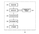
- FIG. 2 is a functional block diagram illustrating an example of functions realized by the image processing apparatus 10 according to the present embodiment.
- the image processing apparatus 10 according to the present embodiment functionally includes an image acquisition unit 20, an area specifying unit 22, a feature amount difference total specifying unit 24, a deformation rule specifying unit 26, a deformation process executing unit 28, and a character recognition unit 30. , Including. These elements are realized mainly by the control unit 12.
- These elements are realized by executing a program installed in the image processing apparatus 10 that is a computer by the control unit of the image processing apparatus 10.
- the program is supplied to the image processing apparatus 10 via a computer-readable recording medium such as a CD-ROM or DVD-ROM, or via a communication network such as the Internet.
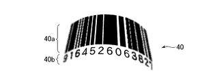
- the image acquisition unit 20 acquires the barcode image 40 read by the reading unit 18 illustrated in FIG.
- the barcode image 40 includes a graphic code 40a and a character string 40b.
- the graphic code 40a and the character string 40b are in a given positional relationship.
- the read barcode image 40 is curved upward and the left and right end portions are blurred.
- the area specifying unit 22 specifies an area occupied by the graphic code 40a (hereinafter referred to as a graphic code area) from the barcode image 40 acquired by the image acquisition unit 20.
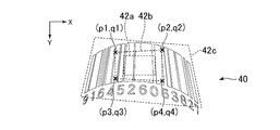
- the region specifying unit 22 uses a plurality of different XY coordinate systems (for example, the right direction of the barcode image 40 acquired by the image acquisition unit 20 is the X axis positive direction and the downward direction is the Y axis positive direction. For each of 0 degree counterclockwise (that is, the XY coordinate system rotated by 30 degrees, 60 degrees, 90 degrees, 120 degrees, and 150 degrees). The identification process of the reference area 42c (see FIG. 4) is executed. Then, the region specifying unit 22 specifies one selected from the plurality of final feature amount calculation reference regions 42c by a method described later as a graphic code region.
- the process for specifying the final feature quantity calculation reference area 42c will be described.
- the barcode image 40 is represented in white.
- FIG. 4 shows an example in which the horizontal direction of the barcode image 40 is the X axis positive direction.
- the area specifying unit 22 first sets an initial feature quantity calculation reference area 42 (hereinafter referred to as an initial set feature quantity calculation reference area 42 a) in the XY coordinate system.
- the initially set feature amount calculation reference region 42a has a predetermined shape, size, and position in the barcode image 40.
- the area specifying unit 22 executes the update process of the feature amount calculation reference area 42 until a given condition is satisfied. Details of the update processing of the feature amount calculation reference area 42 will be described later. Then, the area specifying unit 22 specifies the feature quantity calculation reference area 42 at the time when the predetermined condition is satisfied as the final feature quantity calculation reference area 42c.
- the outline figure of the feature quantity calculation reference area 42 is a rectangle. Then, by updating the positions of the four vertices of the contour graphic in the feature quantity calculation reference area 42, the position, shape and size of the feature quantity calculation reference area 42 are updated.
- the feature quantity calculation reference area 42 in the middle of the process until the final feature quantity calculation reference area 42c is specified is shown as an intermediate state feature quantity calculation reference area 42b.
- the update processing of the feature quantity calculation reference area 42 executed for the midway state feature quantity calculation reference area 42b will be described.
- the pixel coordinate values of the upper left, upper right, lower left, and lower right vertices of the contour figure of the midway state feature amount calculation reference region 42b are (p1, q1), (p2, q2), (p3, respectively). q3) and (p4, q4).
- the feature quantity difference total specifying unit 24 determines a plurality of feature quantity calculation areas based on the feature quantity calculation reference area 42. Specifically, the feature amount difference total specifying unit 24 specifically, for example, for each vertex, a reference pixel that is the vertex itself of the contour figure of the feature amount calculation reference region 42, a pixel at the upper left of the reference pixel, and a pixel above the reference pixel , The upper right pixel of the reference pixel, the left pixel of the reference pixel, the right pixel of the reference pixel, the lower left pixel of the reference pixel, the lower pixel of the reference pixel, and the lower right pixel of the reference pixel. One of them is determined as the vertex of the outline figure in the feature amount calculation area.
- the pixel coordinate values are (p1-1, q1-1), (p1, q1-1), (p1 + 1, q1-1), (p1-1,
- Nine pixels of q1), (p1, q1), (p1 + 1, q1), (p1-1, q1 + 1), (p1, q1 + 1), (p1 + 1, q1 + 1) are the vertices of the contour figure in the feature amount calculation area Selected as.
- 9 ⁇ 9 ⁇ 9 ⁇ 9 6561 feature amount calculation regions are determined. It becomes.
- the difference between the feature amounts of pixels adjacent to each other in two directions (in this embodiment, the X-axis direction and the Y-axis direction) orthogonal to each other (in the present embodiment, may be substantially orthogonal) in the feature amount calculation region (
- a feature value difference total value CTotalDiff which is a total value of luminance differences, is calculated for each feature value calculation region.
- the X component pixel coordinate values of the pixels in the feature amount calculation area where the Y component value of the pixel coordinate value is y are xmin, xmin + 1,. It is assumed that the Y component pixel coordinate values of the pixels in the feature amount calculation region where is is ymin, ymin + 1,..., Ymax.
- a feature amount (in this embodiment, luminance) at the pixel coordinate value (x, y) is expressed as C (x, y).
- the minimum value of the X component pixel coordinate values at the four vertices of the feature amount calculation region is pmin, and the maximum value is pmax.
- the minimum value of the Y component pixel coordinate values at the four vertices of the feature amount calculation region is qmin, and the maximum value is qmax.
- C (xmin + 1, y) ⁇ C (xmin, y) for each of y qmin, qmin + 1,. y)
- ) is the difference between the feature quantity at the pixel coordinate value (xmin + 1, y) and the feature quantity at the pixel coordinate value (xmin, y).
- the value CTotalDiff (x) is calculated.
- C (x, ymin + 1) ⁇ C (x, x) for each of x pmin, pmin + 1,. ymin)
- Then, the feature quantity difference sum specifying unit 24 sums up the Y axis feature quantity difference subtotal values CSubtotalDiff (y) calculated for x pmin, pmin + 1,. Calculate CTotalDiff (y).
- the feature quantity difference total specifying unit 24 calculates the absolute value of the difference between the X-axis feature quantity difference total value CTotalDiff (x) and the Y-axis feature quantity difference total value CTTotalDiff (y) as the feature quantity difference total in the feature quantity calculation area. It is specified as the value CTotalDiff.
- the area specifying unit 22 does not satisfy a predetermined condition (for example, the feature quantity difference total value CTotalDiff is the same in all the feature quantity calculation areas).
- the positions of the four vertices of the contour graphic are updated to the positions of the four vertices of the contour graphic in the feature amount calculation area having the maximum feature value difference total CTTotalDiff.
- the feature quantity calculation reference area 42 is updated.
- the area specifying unit 22 sets the feature quantity calculation reference area 42 when a given condition is satisfied, for example, the feature quantity difference total value CTTotalDiff is the same in all feature quantity calculation areas, as the final feature quantity calculation reference area. It is specified as 42c.
- the final feature quantity calculation reference region 42c specified in this way is considered to be a region where the feature quantity difference total value CTotalDiff is locally the largest.
- the region specifying unit 22 specifies the final feature amount calculation reference region 42c for each of the plurality of XY coordinate systems as described above. Then, the final feature quantity calculation reference area 42c having the maximum feature quantity difference total value CTTotalDiff corresponding to the final feature quantity calculation reference area 42c is specified as the graphic code area.
- the graphic code area specified in this way is considered to be substantially circumscribed by the graphic code 40a.
- the deformation rule specifying unit 26 specifies a deformation rule for deforming the contour graphic of the graphic code area specified by the area specifying unit 22 into a known type of graphic.
- a conversion matrix for converting a quadrangle that is a contour graphic in the graphic code area into a rectangle having a known aspect ratio is specified.
- the deformation process executing unit 28 performs deformation (for example, linear conversion or affine conversion using a conversion matrix) on the entire barcode image 40 according to the deformation rule specified by the deformation rule specifying unit 26.
- FIG. 5 shows an example of the barcode image 40 after being deformed by the deformation processing execution unit 28.
- the character recognition unit 30 has a given positional relationship with respect to the graphic code 40a in the barcode image 40 after deformation by the deformation processing execution unit 28 (for example, the graphic code when the graphic code 40a is arranged horizontally) Character recognition for the character string 40b is performed by executing the OCR process on the character string 40b arranged in the upper or lower area 40a.
- the character string 40b is deformed and the OCR process is executed, the accuracy of character recognition is improved. For example, even when all or part of the barcode image 40 is blurred and the information expressed by the graphic code 40a of the barcode image 40 cannot be decoded, the character recognition result by the character recognition unit 30 is determined as the graphic code 40a. Is processed as a result of decoding the information represented by the graphic code 40a, so that various information processing using the result of decoding the information represented by the graphic code 40a (for example, the ID represented by the character string 40b resulting from the character recognition) It is possible to reduce the possibility that the detailed information of the associated products will not be executable).
- the present invention can be applied if all or part of the barcode image 40 is difficult to identify and the place where it is difficult to identify is deformed.
- the present invention can be applied to a scene where the barcode image 40 is not blurred and a part of the barcode image 40 is dirty.
- the area specifying unit 22 changes the initial set feature quantity calculation reference area 42a if the feature quantity difference total value CTTotalDiff in the final feature quantity calculation reference area 42c is equal to or less than a predetermined reference value, and then calculates the final feature quantity calculation.
- the reference area 42c may be specified again.
- the area specifying unit 22 may specify a polygon (for example, a quadrangle) circumscribing the graphic code 40a as the graphic code area.
- the deformation rule specifying unit 26 may specify a deformation rule for deforming the contour graphic of the graphic code area specified by the area specifying unit 22 into a graphic having a known shape and size.
- the image processing apparatus 10 is set to 0 degrees, 30 degrees, 60 degrees, and 90 degrees counterclockwise with reference to the case where the horizontal direction of the barcode image 40 acquired by the image acquisition unit 20 is the X axis positive direction.
- the frequency feature amount of the histogram of the barcode image 40 in the X-axis direction and the frequency feature amount of the histogram of the barcode image 40 in the X-axis direction are calculated for each of a plurality of XY coordinate systems rotated by 120 degrees and 150 degrees.
- a direction specifying unit that specifies the X-axis direction and the Y-axis direction of the XY coordinate system in which the difference in the frequency feature amount satisfies a given condition (for example, becomes maximum) may be included.
- the region specifying unit 22 may specify the final feature amount calculation reference region 42c specified for the XY coordinate system including the X-axis direction and the Y-axis direction specified by the direction specifying unit as the graphic code region. .
- the feature amount difference total specifying unit 24 may obtain at least one partial image (for example, obtained by dividing the barcode image 40), instead of the sum of the difference between the feature amounts of adjacent pixels.
- the sum of the difference between the feature amounts of a partial image including one pixel may be used as the feature amount difference total value CTotalDiff.
- the deformation by the deformation rule is not limited to linear transformation or affine transformation.
- a known method for correcting nonlinear distortion specifically, for example, nonlinear local geometric correction method or linear local geometric correction method.
- the character recognition accuracy of the character string 40b may be improved.
- the feature quantity calculation reference area 42 and the figure code area may be polygons composed of five or more vertices.
- a curve may be included in a side included in the feature amount calculation reference area 42 or the graphic code area.
- the area specifying unit 22 may specify a graphic code area where the feature value difference total value CTTotalDiff is maximum using a known local search method other than the above-described method, for example.
- the image processing apparatus 10 may be composed of a plurality of cases.
- the specific barcode image 40 described in the drawing is an example, and the scope of application of the present invention is not limited to the barcode image 40 described in the drawing.
Landscapes
- Engineering & Computer Science (AREA)
- Physics & Mathematics (AREA)
- Theoretical Computer Science (AREA)
- Artificial Intelligence (AREA)
- Computer Vision & Pattern Recognition (AREA)
- General Physics & Mathematics (AREA)
- Health & Medical Sciences (AREA)
- Electromagnetism (AREA)
- General Health & Medical Sciences (AREA)
- Toxicology (AREA)
- Life Sciences & Earth Sciences (AREA)
- Bioinformatics & Cheminformatics (AREA)
- Bioinformatics & Computational Biology (AREA)
- Data Mining & Analysis (AREA)
- Evolutionary Biology (AREA)
- Evolutionary Computation (AREA)
- General Engineering & Computer Science (AREA)
- Character Input (AREA)
- Image Analysis (AREA)
- Character Discrimination (AREA)
- Editing Of Facsimile Originals (AREA)
- Processing Or Creating Images (AREA)
Abstract
Description
Claims (11)
- 所与の位置関係にある図形コードと当該図形コードの外側に配置された少なくとも1つの文字とが含まれる画像を取得する画像取得手段と、
前記画像取得手段により取得される画像に含まれる図形コードを既知の種類の図形に変形する変形規則を特定する変形規則特定手段と、
前記画像取得手段により取得される画像に含まれる文字に対して前記変形規則特定手段により特定される変形規則に従う変形処理を実行する変形処理実行手段と、
を含むことを特徴とする画像処理装置。 - 前記画像取得手段により取得される画像内の領域の、互いに略直交する二方向のそれぞれについて、当該領域内の、当該方向に沿って互いに隣接する部分画像の特徴量の差の合計を特定する特徴量差合計特定手段と、
前記特徴量差合計特定手段により前記二方向について特定される前記合計の差が、合計の差に関する所与の条件を満足する、前記画像取得手段により取得される画像内の領域を特定する領域特定手段と、をさらに含み、
前記変形規則特定手段は、前記領域特定手段による特定結果である領域の輪郭図形を既知の種類の図形に変形する変形規則を特定する、
ことを特徴とする請求項1に記載の画像処理装置。 - 前記領域特定手段が、前記特徴量差合計特定手段により前記二方向について特定される前記合計の差が最大となる、前記画像取得手段により取得される画像内の領域を特定する、
ことを特徴とする請求項2に記載の情報処理装置。 - 前記特徴量差合計特定手段は、前記画像取得手段により取得される画像内の領域の、互いに略直交する二方向のそれぞれについて、当該領域内の、当該方向に沿って互いに隣接する画素の輝度の差の合計を特定する、
ことを特徴とする請求項2又は3に記載の画像処理装置。 - 前記領域特定手段は、複数の前記二方向についての領域の特定を実行し、
前記変形規則特定手段は、前記領域特定手段による特定結果である、それぞれが互いに異なる前記二方向に対応付けられる複数の領域のうち、前記特徴量差合計特定手段により特定される前記合計の差が最大となる領域の輪郭図形を既知の種類の図形に変形する変形規則を特定する、
ことを特徴とする請求項2から4のいずれか一項に記載の画像処理装置。 - 互いに略直交する二方向であって、前記画像取得手段により取得される画像の少なくとも一部について各方向のヒストグラムの周波数特徴量の違いが、周波数特徴量の違いに関する所与の条件を満足する二方向を特定する方向特定手段、をさらに含み、
前記特徴量差合計特定手段は、前記方向特定手段により特定される二方向のそれぞれについて、当該方向に沿って互いに隣接する部分画像の特徴量の差の合計を特定する、
ことを特徴とする請求項2から4のいずれか一項に記載の画像処理装置。 - 前記変形規則特定手段は、前記画像取得手段により取得される画像に含まれる図形コードを既知の形状の図形に変形する変形規則を特定する、
ことを特徴とする請求項1から6のいずれか一項に記載の画像処理装置。 - 前記変形処理実行手段による変形処理の実行後の文字を認識する文字認識手段、をさらに含む、
ことを特徴とする請求項1から7のいずれか一項に記載の画像処理装置。 - 所与の位置関係にある図形コードと当該図形コードの外側に配置された少なくとも1つの文字とが含まれる画像を取得する画像取得ステップと、
前記画像取得ステップにより取得される画像に含まれる図形コードを既知の種類の図形に変形する変形規則を特定する変形規則特定ステップと、
前記画像取得ステップにより取得される画像に含まれる文字に対して前記変形規則特定ステップにより特定される変形規則に従う変形処理を実行する変形処理実行ステップと、
を含むことを特徴とする画像処理方法。 - 所与の位置関係にある図形コードと当該図形コードの外側に配置された少なくとも1つの文字とが含まれる画像を取得する画像取得手段、
前記画像取得手段により取得される画像に含まれる図形コードを既知の種類の図形に変形する変形規則を特定する変形規則特定手段、
前記画像取得手段により取得される画像に含まれる文字に対して前記変形規則特定手段により特定される変形規則に従う変形処理を実行する変形処理実行手段、
としてコンピュータを機能させることを特徴とするプログラム。 - 所与の位置関係にある図形コードと当該図形コードの外側に配置された少なくとも1つの文字とが含まれる画像を取得する画像取得手段、
前記画像取得手段により取得される画像に含まれる図形コードを既知の種類の図形に変形する変形規則を特定する変形規則特定手段、
前記画像取得手段により取得される画像に含まれる文字に対して前記変形規則特定手段により特定される変形規則に従う変形処理を実行する変形処理実行手段、
としてコンピュータを機能させることを特徴とするプログラムを記録した記録媒体。
Priority Applications (9)
| Application Number | Priority Date | Filing Date | Title |
|---|---|---|---|
| EP11866685.8A EP2634725B1 (en) | 2011-05-31 | 2011-05-31 | Image processing device, image processing method, program, and recording medium |
| CA2816247A CA2816247C (en) | 2011-05-31 | 2011-05-31 | Image processing device, image processing method, program, and recording medium |
| KR1020137014292A KR101322953B1 (ko) | 2011-05-31 | 2011-05-31 | 화상 처리 장치, 화상 처리 방법 및 기록 매체 |
| CN201180071114.XA CN103562931B (zh) | 2011-05-31 | 2011-05-31 | 图像处理装置、图像处理方法 |
| PCT/JP2011/062486 WO2012164686A1 (ja) | 2011-05-31 | 2011-05-31 | 画像処理装置、画像処理方法、プログラム及び記録媒体 |
| US13/824,155 US8781251B2 (en) | 2011-05-31 | 2011-05-31 | Image processing device and image processing method deformation processing based on a rule |
| BR112013013425-9A BR112013013425B1 (pt) | 2011-05-31 | 2011-05-31 | dispositivo de processamento de imagem, método de processamento de imagem, e, meio de armazenamento legível por computador |
| JP2011547634A JP4917698B1 (ja) | 2011-05-31 | 2011-05-31 | 画像処理装置、画像処理方法、プログラム及び記録媒体 |
| ES11866685.8T ES2603153T3 (es) | 2011-05-31 | 2011-05-31 | Dispositivo de procesamiento de imágenes, procedimiento de procesamiento de imágenes, programa y soporte de grabación |
Applications Claiming Priority (1)
| Application Number | Priority Date | Filing Date | Title |
|---|---|---|---|
| PCT/JP2011/062486 WO2012164686A1 (ja) | 2011-05-31 | 2011-05-31 | 画像処理装置、画像処理方法、プログラム及び記録媒体 |
Publications (1)
| Publication Number | Publication Date |
|---|---|
| WO2012164686A1 true WO2012164686A1 (ja) | 2012-12-06 |
Family
ID=46243772
Family Applications (1)
| Application Number | Title | Priority Date | Filing Date |
|---|---|---|---|
| PCT/JP2011/062486 Ceased WO2012164686A1 (ja) | 2011-05-31 | 2011-05-31 | 画像処理装置、画像処理方法、プログラム及び記録媒体 |
Country Status (9)
| Country | Link |
|---|---|
| US (1) | US8781251B2 (ja) |
| EP (1) | EP2634725B1 (ja) |
| JP (1) | JP4917698B1 (ja) |
| KR (1) | KR101322953B1 (ja) |
| CN (1) | CN103562931B (ja) |
| BR (1) | BR112013013425B1 (ja) |
| CA (1) | CA2816247C (ja) |
| ES (1) | ES2603153T3 (ja) |
| WO (1) | WO2012164686A1 (ja) |
Cited By (3)
| Publication number | Priority date | Publication date | Assignee | Title |
|---|---|---|---|---|
| JP2013148980A (ja) * | 2012-01-17 | 2013-08-01 | Denso Wave Inc | 二次元コード読み取り装置 |
| JP2014115811A (ja) * | 2012-12-10 | 2014-06-26 | Hitachi Omron Terminal Solutions Corp | 光学読取装置、光学的シンボルを読み取る方法、プログラム、記録紙葉類 |
| JP2022071136A (ja) * | 2020-09-01 | 2022-05-13 | 東芝テック株式会社 | コード認識装置 |
Families Citing this family (7)
| Publication number | Priority date | Publication date | Assignee | Title |
|---|---|---|---|---|
| JP6162584B2 (ja) * | 2013-11-21 | 2017-07-12 | 株式会社オプトエレクトロニクス | 光学的情報読取装置の画像処理方法及び光学的情報読取装置 |
| CN106682560B (zh) * | 2016-12-28 | 2020-01-31 | 深圳市共进电子股份有限公司 | 二维码识别方法、装置和系统 |
| DE102018107950B4 (de) | 2017-04-18 | 2025-02-20 | Canon Kabushiki Kaisha | Bildverarbeitungsvorrichtung, bildverarbeitungsverfahren und bildaufnahmevorrichtung |
| JP2019061527A (ja) * | 2017-09-27 | 2019-04-18 | 富士通株式会社 | データ判定装置、ライブラリ装置、及びデータ判定プログラム |
| JP7036874B2 (ja) * | 2020-09-01 | 2022-03-15 | 東芝テック株式会社 | コード認識装置 |
| CN114881064B (zh) * | 2022-06-17 | 2025-09-16 | 河南大学 | 一种褶皱条形码识别方法 |
| CN118396009B (zh) * | 2024-06-24 | 2024-10-29 | 深圳盈达信息科技有限公司 | 一种条码自动识别方法、系统、存储介质及电子设备 |
Citations (5)
| Publication number | Priority date | Publication date | Assignee | Title |
|---|---|---|---|---|
| JPH07121673A (ja) * | 1993-10-28 | 1995-05-12 | Hitachi Ltd | 情報提供方法およびその装置 |
| JP2000511320A (ja) | 1997-04-24 | 2000-08-29 | ユナイテッド パーセル サービス オブ アメリカ,インコーポレイテッド | 光学的文字認識(ocr)支援のバーコード解読システム及び方法 |
| JP2006018655A (ja) * | 2004-07-02 | 2006-01-19 | Ricoh Co Ltd | 文書処理システム |
| JP2007520001A (ja) * | 2004-01-14 | 2007-07-19 | インターナショナル バーコード コーポレイション | スキャン可能な歪補償用仮想バーコード画像 |
| JP2009129269A (ja) * | 2007-11-26 | 2009-06-11 | Nec Soft Ltd | 情報読取装置及び情報読取方法 |
Family Cites Families (17)
| Publication number | Priority date | Publication date | Assignee | Title |
|---|---|---|---|---|
| US6947571B1 (en) * | 1999-05-19 | 2005-09-20 | Digimarc Corporation | Cell phones with optical capabilities, and related applications |
| JP2001326847A (ja) * | 2000-05-16 | 2001-11-22 | Fuji Photo Film Co Ltd | 画像撮像装置 |
| US7385743B2 (en) * | 2001-10-16 | 2008-06-10 | Accu-Sort Systems, Inc. | Linear imager rescaling method |
| JP2003168071A (ja) * | 2001-11-30 | 2003-06-13 | Sanyo Electric Co Ltd | 2次元バーコードの読み取り方法 |
| US20040003052A1 (en) * | 2002-03-20 | 2004-01-01 | Fuji Photo Film Co., Ltd. | Data detection method, apparatus, and program |
| US7365875B2 (en) * | 2002-05-14 | 2008-04-29 | Canon Kabushiki Kaisha | Image processing apparatus, image processing method, program, and recording medium |
| US7567360B2 (en) * | 2003-03-27 | 2009-07-28 | Canon Kabushiki Kaisha | Image forming system, method and program of controlling image forming system, and storage medium |
| US7337970B2 (en) * | 2004-12-03 | 2008-03-04 | Symbol Technologies, Inc. | Barcode scanner decoding |
| JP4617328B2 (ja) * | 2006-07-20 | 2011-01-26 | キヤノン株式会社 | 画像処理装置及びその処理方法 |
| US7780084B2 (en) * | 2007-06-29 | 2010-08-24 | Microsoft Corporation | 2-D barcode recognition |
| US8199370B2 (en) * | 2007-08-29 | 2012-06-12 | Scientific Games International, Inc. | Enhanced scanner design |
| US8379914B2 (en) * | 2008-01-18 | 2013-02-19 | Mitek Systems, Inc. | Systems and methods for mobile image capture and remittance processing |
| MX2011009742A (es) * | 2009-03-17 | 2011-11-02 | Scientific Games Holdings Ltd | Firma optica para permitir correccion de imagen. |
| CN101882210B (zh) * | 2010-06-01 | 2012-06-27 | 福建新大陆电脑股份有限公司 | 矩阵式二维条码解码芯片及其解码方法 |
| CN101908125B (zh) * | 2010-06-01 | 2014-07-02 | 福建新大陆电脑股份有限公司 | Qr码条码解码芯片及其解码方法 |
| CN101882207B (zh) * | 2010-06-01 | 2012-06-20 | 福建新大陆电脑股份有限公司 | Data Matrix码条码解码芯片及其解码方法 |
| US8792748B2 (en) * | 2010-10-12 | 2014-07-29 | International Business Machines Corporation | Deconvolution of digital images |
-
2011
- 2011-05-31 KR KR1020137014292A patent/KR101322953B1/ko active Active
- 2011-05-31 EP EP11866685.8A patent/EP2634725B1/en active Active
- 2011-05-31 WO PCT/JP2011/062486 patent/WO2012164686A1/ja not_active Ceased
- 2011-05-31 US US13/824,155 patent/US8781251B2/en active Active
- 2011-05-31 ES ES11866685.8T patent/ES2603153T3/es active Active
- 2011-05-31 JP JP2011547634A patent/JP4917698B1/ja active Active
- 2011-05-31 CN CN201180071114.XA patent/CN103562931B/zh active Active
- 2011-05-31 CA CA2816247A patent/CA2816247C/en active Active
- 2011-05-31 BR BR112013013425-9A patent/BR112013013425B1/pt active IP Right Grant
Patent Citations (5)
| Publication number | Priority date | Publication date | Assignee | Title |
|---|---|---|---|---|
| JPH07121673A (ja) * | 1993-10-28 | 1995-05-12 | Hitachi Ltd | 情報提供方法およびその装置 |
| JP2000511320A (ja) | 1997-04-24 | 2000-08-29 | ユナイテッド パーセル サービス オブ アメリカ,インコーポレイテッド | 光学的文字認識(ocr)支援のバーコード解読システム及び方法 |
| JP2007520001A (ja) * | 2004-01-14 | 2007-07-19 | インターナショナル バーコード コーポレイション | スキャン可能な歪補償用仮想バーコード画像 |
| JP2006018655A (ja) * | 2004-07-02 | 2006-01-19 | Ricoh Co Ltd | 文書処理システム |
| JP2009129269A (ja) * | 2007-11-26 | 2009-06-11 | Nec Soft Ltd | 情報読取装置及び情報読取方法 |
Non-Patent Citations (1)
| Title |
|---|
| See also references of EP2634725A4 |
Cited By (4)
| Publication number | Priority date | Publication date | Assignee | Title |
|---|---|---|---|---|
| JP2013148980A (ja) * | 2012-01-17 | 2013-08-01 | Denso Wave Inc | 二次元コード読み取り装置 |
| JP2014115811A (ja) * | 2012-12-10 | 2014-06-26 | Hitachi Omron Terminal Solutions Corp | 光学読取装置、光学的シンボルを読み取る方法、プログラム、記録紙葉類 |
| JP2022071136A (ja) * | 2020-09-01 | 2022-05-13 | 東芝テック株式会社 | コード認識装置 |
| JP7304992B2 (ja) | 2020-09-01 | 2023-07-07 | 東芝テック株式会社 | コード認識装置 |
Also Published As
| Publication number | Publication date |
|---|---|
| KR20130077898A (ko) | 2013-07-09 |
| EP2634725A1 (en) | 2013-09-04 |
| EP2634725A4 (en) | 2014-06-11 |
| JPWO2012164686A1 (ja) | 2014-07-31 |
| EP2634725B1 (en) | 2016-08-31 |
| JP4917698B1 (ja) | 2012-04-18 |
| BR112013013425B1 (pt) | 2021-03-02 |
| BR112013013425A2 (pt) | 2016-10-11 |
| CA2816247A1 (en) | 2012-12-06 |
| US8781251B2 (en) | 2014-07-15 |
| CN103562931B (zh) | 2016-12-07 |
| CA2816247C (en) | 2016-02-23 |
| US20130177245A1 (en) | 2013-07-11 |
| KR101322953B1 (ko) | 2013-10-29 |
| ES2603153T3 (es) | 2017-02-23 |
| CN103562931A (zh) | 2014-02-05 |
Similar Documents
| Publication | Publication Date | Title |
|---|---|---|
| JP4917698B1 (ja) | 画像処理装置、画像処理方法、プログラム及び記録媒体 | |
| CN114529925B (zh) | 一种全线表表格结构识别方法 | |
| JP4738469B2 (ja) | 画像処理装置、画像処理プログラムおよび画像処理方法 | |
| JP2012203458A (ja) | 画像処理装置及びプログラム | |
| CN115063279A (zh) | 一种文本水印图像的预处理方法和装置 | |
| Kim et al. | Sredgenet: Edge enhanced single image super resolution using dense edge detection network and feature merge network | |
| JP2012018494A (ja) | バーコードシンボル読取装置、バーコードシンボル読取方法及びコンピュータプログラム | |
| JP2007241356A (ja) | 画像処理装置および画像処理プログラム | |
| JP5200786B2 (ja) | 差分抽出装置及び差分抽出プログラム | |
| US20190147238A1 (en) | Information processing apparatus, information processing method, and storage medium | |
| JP6815712B1 (ja) | 画像処理システム、画像処理方法、画像処理プログラム、画像処理サーバ、及び学習モデル | |
| JP5618719B2 (ja) | 画像処理装置、その方法およびプログラム | |
| CN107122818B (zh) | 一种无位置标志的图像码及其生成与解析方法 | |
| JP5563390B2 (ja) | 画像処理装置およびその制御方法、及びプログラム | |
| JP2012015957A (ja) | 画像処理装置、画像処理方法、及びコンピュータプログラム | |
| CN111681161B (zh) | 折叠二维码图像的还原方法、设备及计算机可读存储介质 | |
| JP2006023976A (ja) | パラメータ設定方法、画像パターン抽出方法、パラメータ設定装置、画像パターン抽出装置、およびこれら方法のプログラム | |
| JP2010182167A (ja) | 画像処理装置および画像処理方法 | |
| JP4910635B2 (ja) | 画像処理装置及び画像処理プログラム | |
| JP4869364B2 (ja) | 画像処理装置および画像処理方法 | |
| JP4356368B2 (ja) | 文書画像傾き検知方法、文書画像傾き補正方法、文書画像傾き検知装置、及び文書画像傾き補正装置 | |
| JP2011146031A (ja) | 情報処理装置、情報処理方法、コンピュータプログラム、記録媒体 | |
| JP6950436B2 (ja) | 画像キャプチャ用コンピュータプログラム、画像キャプチャ装置及び画像キャプチャ方法 | |
| JP3582143B2 (ja) | 地図入力システムにおける家屋認識方法 | |
| JP2005173940A (ja) | 画像処理方法、画像処理装置、及びコンピュータプログラム |
Legal Events
| Date | Code | Title | Description |
|---|---|---|---|
| ENP | Entry into the national phase |
Ref document number: 2011547634 Country of ref document: JP Kind code of ref document: A |
|
| 121 | Ep: the epo has been informed by wipo that ep was designated in this application |
Ref document number: 11866685 Country of ref document: EP Kind code of ref document: A1 |
|
| WWE | Wipo information: entry into national phase |
Ref document number: 13824155 Country of ref document: US |
|
| ENP | Entry into the national phase |
Ref document number: 2816247 Country of ref document: CA |
|
| REEP | Request for entry into the european phase |
Ref document number: 2011866685 Country of ref document: EP |
|
| WWE | Wipo information: entry into national phase |
Ref document number: 2011866685 Country of ref document: EP |
|
| ENP | Entry into the national phase |
Ref document number: 20137014292 Country of ref document: KR Kind code of ref document: A |
|
| NENP | Non-entry into the national phase |
Ref country code: DE |
|
| REG | Reference to national code |
Ref country code: BR Ref legal event code: B01A Ref document number: 112013013425 Country of ref document: BR |
|
| ENP | Entry into the national phase |
Ref document number: 112013013425 Country of ref document: BR Kind code of ref document: A2 Effective date: 20130529 |