WO2012164884A1 - ヒューズ板、およびそれを具備する電池ブロック - Google Patents
ヒューズ板、およびそれを具備する電池ブロック Download PDFInfo
- Publication number
- WO2012164884A1 WO2012164884A1 PCT/JP2012/003412 JP2012003412W WO2012164884A1 WO 2012164884 A1 WO2012164884 A1 WO 2012164884A1 JP 2012003412 W JP2012003412 W JP 2012003412W WO 2012164884 A1 WO2012164884 A1 WO 2012164884A1
- Authority
- WO
- WIPO (PCT)
- Prior art keywords
- fuse
- plate
- metal plate
- insulating resin
- connection
- Prior art date
- Legal status (The legal status is an assumption and is not a legal conclusion. Google has not performed a legal analysis and makes no representation as to the accuracy of the status listed.)
- Ceased
Links
Images


Classifications
-
- H—ELECTRICITY
- H01—ELECTRIC ELEMENTS
- H01H—ELECTRIC SWITCHES; RELAYS; SELECTORS; EMERGENCY PROTECTIVE DEVICES
- H01H85/00—Protective devices in which the current flows through a part of fusible material and this current is interrupted by displacement of the fusible material when this current becomes excessive
- H01H85/02—Details
- H01H85/04—Fuses, i.e. expendable parts of the protective device, e.g. cartridges
- H01H85/05—Component parts thereof
- H01H85/055—Fusible members
- H01H85/08—Fusible members characterised by the shape or form of the fusible member
-
- H—ELECTRICITY
- H01—ELECTRIC ELEMENTS
- H01H—ELECTRIC SWITCHES; RELAYS; SELECTORS; EMERGENCY PROTECTIVE DEVICES
- H01H69/00—Apparatus or processes for the manufacture of emergency protective devices
- H01H69/02—Manufacture of fuses
-
- H—ELECTRICITY
- H01—ELECTRIC ELEMENTS
- H01H—ELECTRIC SWITCHES; RELAYS; SELECTORS; EMERGENCY PROTECTIVE DEVICES
- H01H85/00—Protective devices in which the current flows through a part of fusible material and this current is interrupted by displacement of the fusible material when this current becomes excessive
- H01H85/02—Details
- H01H85/0241—Structural association of a fuse and another component or apparatus
-
- H—ELECTRICITY
- H01—ELECTRIC ELEMENTS
- H01H—ELECTRIC SWITCHES; RELAYS; SELECTORS; EMERGENCY PROTECTIVE DEVICES
- H01H85/00—Protective devices in which the current flows through a part of fusible material and this current is interrupted by displacement of the fusible material when this current becomes excessive
- H01H85/02—Details
- H01H85/04—Fuses, i.e. expendable parts of the protective device, e.g. cartridges
- H01H85/05—Component parts thereof
- H01H85/055—Fusible members
- H01H85/12—Two or more separate fusible members in parallel
-
- H—ELECTRICITY
- H01—ELECTRIC ELEMENTS
- H01M—PROCESSES OR MEANS, e.g. BATTERIES, FOR THE DIRECT CONVERSION OF CHEMICAL ENERGY INTO ELECTRICAL ENERGY
- H01M10/00—Secondary cells; Manufacture thereof
- H01M10/42—Methods or arrangements for servicing or maintenance of secondary cells or secondary half-cells
- H01M10/4207—Methods or arrangements for servicing or maintenance of secondary cells or secondary half-cells for several batteries or cells simultaneously or sequentially
-
- H—ELECTRICITY
- H01—ELECTRIC ELEMENTS
- H01M—PROCESSES OR MEANS, e.g. BATTERIES, FOR THE DIRECT CONVERSION OF CHEMICAL ENERGY INTO ELECTRICAL ENERGY
- H01M10/00—Secondary cells; Manufacture thereof
- H01M10/42—Methods or arrangements for servicing or maintenance of secondary cells or secondary half-cells
- H01M10/425—Structural combination with electronic components, e.g. electronic circuits integrated to the outside of the casing
-
- H—ELECTRICITY
- H01—ELECTRIC ELEMENTS
- H01M—PROCESSES OR MEANS, e.g. BATTERIES, FOR THE DIRECT CONVERSION OF CHEMICAL ENERGY INTO ELECTRICAL ENERGY
- H01M50/00—Constructional details or processes of manufacture of the non-active parts of electrochemical cells other than fuel cells, e.g. hybrid cells
- H01M50/50—Current conducting connections for cells or batteries
- H01M50/572—Means for preventing undesired use or discharge
- H01M50/574—Devices or arrangements for the interruption of current
- H01M50/583—Devices or arrangements for the interruption of current in response to current, e.g. fuses
-
- H—ELECTRICITY
- H01—ELECTRIC ELEMENTS
- H01H—ELECTRIC SWITCHES; RELAYS; SELECTORS; EMERGENCY PROTECTIVE DEVICES
- H01H85/00—Protective devices in which the current flows through a part of fusible material and this current is interrupted by displacement of the fusible material when this current becomes excessive
- H01H85/02—Details
- H01H85/04—Fuses, i.e. expendable parts of the protective device, e.g. cartridges
- H01H85/05—Component parts thereof
- H01H85/143—Electrical contacts; Fastening fusible members to such contacts
-
- H—ELECTRICITY
- H01—ELECTRIC ELEMENTS
- H01H—ELECTRIC SWITCHES; RELAYS; SELECTORS; EMERGENCY PROTECTIVE DEVICES
- H01H85/00—Protective devices in which the current flows through a part of fusible material and this current is interrupted by displacement of the fusible material when this current becomes excessive
- H01H85/02—Details
- H01H85/20—Bases for supporting the fuse; Separate parts thereof
- H01H85/205—Electric connections to contacts on the base
-
- H—ELECTRICITY
- H01—ELECTRIC ELEMENTS
- H01M—PROCESSES OR MEANS, e.g. BATTERIES, FOR THE DIRECT CONVERSION OF CHEMICAL ENERGY INTO ELECTRICAL ENERGY
- H01M2200/00—Safety devices for primary or secondary batteries
- H01M2200/10—Temperature sensitive devices
- H01M2200/103—Fuse
-
- Y—GENERAL TAGGING OF NEW TECHNOLOGICAL DEVELOPMENTS; GENERAL TAGGING OF CROSS-SECTIONAL TECHNOLOGIES SPANNING OVER SEVERAL SECTIONS OF THE IPC; TECHNICAL SUBJECTS COVERED BY FORMER USPC CROSS-REFERENCE ART COLLECTIONS [XRACs] AND DIGESTS
- Y02—TECHNOLOGIES OR APPLICATIONS FOR MITIGATION OR ADAPTATION AGAINST CLIMATE CHANGE
- Y02E—REDUCTION OF GREENHOUSE GAS [GHG] EMISSIONS, RELATED TO ENERGY GENERATION, TRANSMISSION OR DISTRIBUTION
- Y02E60/00—Enabling technologies; Technologies with a potential or indirect contribution to GHG emissions mitigation
- Y02E60/10—Energy storage using batteries
-
- Y—GENERAL TAGGING OF NEW TECHNOLOGICAL DEVELOPMENTS; GENERAL TAGGING OF CROSS-SECTIONAL TECHNOLOGIES SPANNING OVER SEVERAL SECTIONS OF THE IPC; TECHNICAL SUBJECTS COVERED BY FORMER USPC CROSS-REFERENCE ART COLLECTIONS [XRACs] AND DIGESTS
- Y10—TECHNICAL SUBJECTS COVERED BY FORMER USPC
- Y10T—TECHNICAL SUBJECTS COVERED BY FORMER US CLASSIFICATION
- Y10T29/00—Metal working
- Y10T29/49—Method of mechanical manufacture
- Y10T29/49002—Electrical device making
- Y10T29/49107—Fuse making
Definitions
- the present invention relates to a fuse plate and a battery block including the fuse plate.
- a battery block having a desired voltage or current amount can be obtained by combining a plurality of single cells.
- the electrode terminals of the plurality of single cells are connected to one electrode plate. Therefore, when an excessive current flows through the unit cell, the battery block itself may be short-circuited. Therefore, in order to prevent the short circuit, a fuse for cutting off the electrode plate and the unit cell may be provided.
- Patent Document 1 discloses (a) a process of forming an input side terminal portion and a plurality of output side terminal portions by press punching a conductive metal plate, and (b) a fuse of the punched metal plate.
- a method for manufacturing a fuse is disclosed which includes a step of previously molding a region including a portion where a portion is formed with an insulator, and (c) a step of punching and forming a substantially S-shaped fuse portion.
- problems such as complicated manufacturing processes and weak connection strength between the obtained fuse and battery.
- various related technologies have been disclosed (see, for example, Patent Documents 3 to 7), but the above-mentioned problems have not been solved.
- a fuse is provided in each single cell in order to prevent short circuit of the battery block.
- wire bonding has a complicated work process.
- the wiring constituting the fuse may be cut by vibration in the welding operation. Further, while actually using the battery block, the wiring constituting the fuse may be cut by vibration.
- the present invention prevents the fuse wiring from being cut by vibration by optimizing the wiring pattern of the fuse and disposing a resin film that protects the fuse.
- the first of the present invention relates to the fuse plate shown below.
- a fuse plate having a metal plate, a connection portion connected to a battery, a fuse portion connecting the metal plate and the connection portion, and an insulating resin film bonded to the fuse portion, The wiring pattern has a bent portion, and the insulating resin film has a rectangular sheet shape covering one surface of the fuse portion.
- the metal plate includes a suspension section that can vibrate, and the fuse section is connected to the suspension section.
- the fuse plate according to [1] wherein the fuse plate is obtained by patterning a connection portion and a fuse portion by punching and bending a metal plate.
- the second of the present invention relates to a method for manufacturing a fuse plate shown below.
- the method for manufacturing a fuse plate according to [1] A step of preparing a metal plate, a step of forming a connection portion and a fuse portion by punching the metal plate, a step of adjusting a position of the connection portion by bending the metal body, and a connection portion Covering the substrate with an insulating resin film.
- the third of the present invention relates to the battery block shown below.
- a battery block including a plurality of unit cells including two or more electrode terminals, and a fuse plate connected to one electrode terminal of each of the plurality of unit cells,
- the fuse plate includes a metal plate, a connection portion welded to one electrode terminal of each of the plurality of single cells, a fuse portion connecting the metal plate and the connection portion, and an insulating resin film bonded to the fuse portion.
- the fourth of the present invention relates to the fuse plate shown below.
- a metal plate provided with a plurality of openings from the upper surface to the lower surface;
- a first rod-like body and a second rod-like body respectively extending from two points on the periphery of the opening, and a main body portion formed integrally with the other ends of the first rod-like body and the second rod-like body.
- a substantially U-shaped suspension portion formed so as to be able to vibrate, and a bent wiring pattern formed integrally with the suspension portion from the main body portion of the suspension portion toward the joint portion side with the metal plate.
- a fuse portion comprising: A rectangular sheet that extends from a part of the main part of the suspension part to a part of the connection part so as to cover one side of the fuse part, and a connection part that is molded integrally with the fuse part so as to be connected to the battery. And an insulating resin film.
- the fuse plate of the present invention can be easily and easily manufactured by punching and bending a metal plate. Nevertheless, the fuse plate of the present invention is hard to cut the wiring of the fuse portion due to vibration or the like. Therefore, the fuse member is prevented from being cut by vibration during welding work when connecting the fuse plate to the battery or during use of the battery.
- connection portions and fuse portions are provided on the fuse plate of the present invention, a battery block having a plurality of unit cells, each cell having a fuse function is provided. . Therefore, even if any unit cell malfunctions, a short circuit as a battery block is prevented.
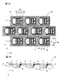
- FIG. 1 is a top perspective view of a fuse plate according to an embodiment.
- FIG. 2A is a top view of the fuse plate according to the embodiment.
- FIG. 2B is a cross-sectional view of the fuse plate according to the embodiment.
- FIG. 3A is a view showing a fuse pattern of a fuse plate according to the embodiment (No. 1).
- FIG. 3B is a view showing a fuse pattern of the fuse plate according to the embodiment (No. 2).
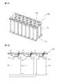
- FIG. 4A is a top perspective view of the battery block of the fuse plate according to the embodiment.
- FIG. 4B is a cross-sectional view of the battery block of the fuse plate according to the embodiment.
- the fuse plate of the present invention includes a metal plate, a connection portion connected to the battery, a fuse portion, and an insulating resin film.
- the fuse plate of the present invention has two or more connection portions, a fuse portion, and an insulating resin film with respect to one metal plate.
- a fuse plate having two or more connection portions, a fuse portion, and an insulating resin film can be used as a fuse plate of a battery block including a plurality of single cells.
- FIG. 1 is a top perspective view of a fuse plate 100 according to an embodiment of the present invention.
- FIG. 2A is a top view of the fuse plate 100.
- FIG. 2B is a cross-sectional view of the fuse plate 100.
- the fuse plate 100 includes (a) a metal plate 10 provided with a plurality of openings 11 from the upper surface 11a to the lower surface 11b, and (b) a first extending from two points 11a and 11c on the periphery of the opening 11.
- the rod-shaped body 40a, the second rod-shaped body 40b, the main body portion 40b formed integrally with the other end of each of the first rod-shaped body 40a and the second rod-shaped body 40c, and substantially U formed so as to vibrate.
- a U-shaped suspension part 40 and (C) a body part 40b of the suspension part 40 are formed integrally and continuously with the suspension part 40 toward the joint side 11a, 11c with the metal plate 10.
- a fuse portion 30 having a bent wiring pattern (d) a connection portion 20 formed integrally with the fuse portion 30 so as to be connectable to the battery, and (e) one of the fuse portions 30.
- the cover has a rectangular sheet-shaped insulating resin film 50 extending from a portion of the body 40b of the suspension unit 40 in a part of the connecting portion 20, a.
- the upper surface 20a of the connecting portion 20 is disposed below the distance D from the lower surface 10b of the metal plate 10. This is because the suspension part 30 can vibrate in the direction of gravity (the Z direction in the drawing), so that the stress can be absorbed even when subjected to stress due to vibration during use.
- the fuse plate 100 can maintain high connection reliability with the battery. Further, since the fuse portion 30 is protected by the insulating resin film 50, it is difficult to cut even when subjected to stress due to vibration.
- the fuse plate 100 is obtained by patterning the opening 11, the suspension 40, the fuse 30 and the connection 20 by punching and bending a metal plate. That is, since the fuse plate 10 can be integrally formed from a metal plate, it can be easily and easily manufactured.
- the fuse disclosed in Patent Document 2 described above has a planar shape as it is press punched from a metal plate.
- the fuse disclosed in Patent Document 2 or the like does not include the three-dimensional suspension unit 30. For this reason, the fuse disclosed in Patent Document 2 cannot absorb stress due to vibration during use, and it is difficult to maintain high connection reliability with the battery.
- the metal plate constituting the fuse plate is preferably a metal plate.
- the metal include aluminum, stainless steel, copper, or brass, and aluminum is preferable.
- the thickness of the metal plate is not particularly limited, but may be about 0.15 to 3 mm. This is to obtain mechanical strength as a member.
- connection part constituting the fuse plate is a metal member connected to the electrode terminal of the battery. Although it does not specifically limit, a connection part is welded to an electrode terminal. It is preferable that the metal which comprises a connection part is the same as that of the above-mentioned metal plate.
- the thickness of the connecting portion is not particularly limited, and may be 0.1 to 0.4 mm, preferably 0.2 to 0.25 mm. If it is too thick, it may be difficult to weld to the battery electrode terminal.
- the connecting portion is at a position different from the surface height of the metal plate. This is because the connection portion is simply connected to the electrode terminal of the battery.
- the fuse part is a fine metal wiring, and the line width may be 0.1 to 0.4 mm.
- the thickness of the metal wire constituting the fuse portion may be 0.1 to 0.4 mm, preferably 0.2 to 0.25 mm.
- the metal of the metal wiring constituting the fuse is preferably the same as the above-described metal plate. If the line width of the metal wiring of the fuse portion is too thick or too thick, the fuse function (function of cutting when excessive current flows) cannot be obtained.
- the metal wiring pattern of the fuse portion has a bent portion, that is, a “bend” (see FIGS. 3A and 3B). This is because the stress of the fuse portion is reduced and it is difficult to cut.
- the metal wiring pattern of the fuse portion only needs to have a bent portion, and the amount of deflection t (see FIG. 3A) is preferably larger than the line width of the fuse pattern.
- the fuse pattern of the fuse portion preferably has two or more bent portions (see FIG. 3B). The two bent portions are preferably positioned opposite to each other with respect to a straight line connecting both ends of the fuse portion (a straight line connecting the connection position to the connection portion and the connection position to the metal plate). This is because by using such a fuse pattern, the stress can be alleviated no matter what direction the stress is applied.
- the insulating resin film is a protective film that protects the fuse portion. As described above, since the fuse portion is a fine metal wiring, it is easily cut by vibration. Therefore, it is preferable to prevent the fuse portion from being cut by attaching an insulating resin film to the fuse portion.
- the insulating resin film is preferably disposed so as to cover at least one surface of the fuse portion. From the viewpoint of improving workability and connection reliability with the battery, a rectangular sheet of insulating resin film that extends from a part of the suspension body to a part of the connection part is placed so as to cover the entire surface of the fuse part. It is preferable to do. This is because the connection reliability with the battery can be improved.
- Patent Document 2 includes a step of providing an insulator in a region including a portion where a fuse is formed between press stamping steps from a metal plate. For this reason, it is necessary to align the perforated portion for each process, and the manufacturing process is complicated.
- the insulating resin film preferably contains a resin component such as polyimide, epoxy resin, or acrylic resin, and an insulating inorganic filler.
- a resin component such as polyimide, epoxy resin, or acrylic resin
- an insulating inorganic filler examples include glass filler.
- the thickness of the insulating resin film is not particularly limited, but may be 50 ⁇ m to 500 ⁇ m.
- the fuse plate preferably includes a suspension section that can vibrate. This is because the suspension portion connects the metal plate and the fuse portion, so that the suspension portion absorbs vibration of the fuse plate, and stress due to vibration is not easily applied to the fuse portion.
- the suspension part is, for example, a U-shaped member, and both ends thereof are supported by a metal plate. A fuse portion is connected to the central portion of the U-shape.
- the volume of the metal constituting the suspension part is larger than the volume of the metal constituting the fuse part. Accordingly, the suspension portion absorbs vibration of the fuse plate and suppresses stress application to the fuse portion.
- the fuse plate of the present invention can be manufactured by stamping and bending a raw metal plate. Specifically, the connecting portion, the fuse portion, and the suspension portion constituting the fuse plate are formed by punching a raw metal plate. As a result, the raw material metal plate becomes a metal plate constituting the fuse. Further, the metal of the connection part, the fuse part and the suspension part is made of the same metal as the metal plate constituting the fuse.
- connection portion it is preferable to compress and thin the portions to be the connection portion, the fuse portion and the suspension portion before punching the raw metal plate. After the compression, members corresponding to the connection portion and the fuse portion are punched and formed.
- the connecting part is bent to make it easy to connect to the battery. Specifically, the surface height of the metal body and the surface height of the connection portion are changed. After bending into a predetermined shape, an insulating resin film is attached to the fuse portion to obtain a fuse plate.
- the battery block of the present invention includes a fuse plate and a plurality of single cells according to an embodiment of the present invention.
- the plurality of single cells have a pair of electrode terminals.
- the connection part of the fuse plate is connected to one electrode of the plurality of unit cells. The connection can be made by welding.
- the battery block may have a plurality of single cells and a member that accommodates them.
- the accommodation member of a single cell is not specifically limited, A plurality of pipe-shaped members are integrated, and a single cell can be accommodated in each pipe-shaped member.
- FIG. 1 is a top perspective view of a fuse plate 100 according to the embodiment.
- the fuse plate 100 includes a metal plate 10 and 20 fuse function units 90.
- Each of the fuse function portions 90 includes a connection portion 20, a fuse portion 30, a suspension portion 40, and an insulating resin film 50 (see FIGS. 2A and 2B).
- FIG. 2A shows a top view of the fuse plate 100 according to the embodiment.
- the connection part 20, the fuse part 30, the insulating resin film 50, and the suspension part 40 are formed on the metal plate 10.
- the suspension portion 40 has a U-shape, and both ends of the U-shape are fixedly supported by the metal plate 10. Then, one of the fuse portions 30 is connected to the central portion of the U-shape. The other side of the fuse part 30 is connected to the connection part 20.
- FIG. 2B is a cross-sectional view of the fuse plate 100 taken along line XX.
- the thickness of the connection portion 20, the fuse portion 30, and the suspension portion 40 is thinner than the thickness of the metal plate 10.
- the fuse function is obtained by making the fuse portion 30 thin.
- the surface height of the metal plate 10 and the surface height of the connection part 20 differ. By changing the height, the connecting portion 20 is easily connected to the electrode terminal of the unit cell (see FIG. 4).
- the U-shaped suspension portion 40 tries to absorb the vibration. Therefore, the fuse part 30 connected to the suspension part 40 is not easily subjected to stress due to vibration. Furthermore, since the fuse portion 30 is protected by the insulating resin film 50, it is difficult to cut even when subjected to stress due to vibration.
- FIG. 3A and 3B show examples of metal wiring patterns constituting the fuse portion 30 of the fuse plate 100.
- FIG. 3A The wiring pattern of the fuse part 30 shown in FIG. 3A has a bent part 31.
- the degree of bending t may be larger than the width of the wiring.
- the fuse part 30 shown in FIG. 3B has a first bent part 31 and a second bent part 32.
- the metal wiring constituting the fuse portion 30 is bent, and the stress load due to vibration is easily relieved.
- the first bent portion 31 and the second bent portion with respect to a straight line connecting the connecting portion of the fuse portion 30 with the connecting portion 20 and the connecting portion with the suspension portion 40.
- 32 is on the opposite side, the stress is more easily relaxed.
- FIG. 4A shows a battery block 200 including one fuse plate 100.
- the battery block 200 includes a total of 20 unit cells 150.
- the fuse plate 100 is connected to one electrode of the unit cell 150.
- FIG. 4B shows a cross section of a connection portion between the fuse plate 100 and the unit cell 150 of the battery block 200. As shown in FIG. 4B, the electrode terminal 151 of the unit cell 150 and the connection portion 20 of the fuse plate 100 are connected.
- the connection can be a weld. Although vibration may occur during the welding operation, stress is not easily applied to the fuse portion 30 of the fuse plate 100, so that the wiring of the fuse portion is not cut.
- the fuse plate of the present invention can be obtained simply and at low cost by punching and bending a metal plate. In addition, cutting of fine metal wirings constituting the fuse portion is suppressed. Therefore, it can be used as a fuse plate of a battery block including a single cell or a plurality of single cells. And a cell and a fuse board can be connected by welding which a vibration tends to generate
- the battery block including the fuse plate of the present invention is less likely to cause the fuse to be cut by vibration. Therefore, the battery block of the present invention can be suitably used in an environment that is susceptible to vibration, such as a storage battery for automobiles.
Landscapes
- Engineering & Computer Science (AREA)
- Manufacturing & Machinery (AREA)
- Chemical & Material Sciences (AREA)
- Chemical Kinetics & Catalysis (AREA)
- Electrochemistry (AREA)
- General Chemical & Material Sciences (AREA)
- Microelectronics & Electronic Packaging (AREA)
- Power Engineering (AREA)
- Fuses (AREA)
- Connection Of Batteries Or Terminals (AREA)
- Battery Mounting, Suspending (AREA)
- Protection Of Static Devices (AREA)
- Charge And Discharge Circuits For Batteries Or The Like (AREA)
Abstract
Description
また特許文献2には、(イ)導電性の金属板をプレス打ち抜き加工することにより、入力側端子部、複数の出力側端子部を形成する工程と、(ロ)打ち抜かれた金属板のヒューズ部が形成される箇所を含む領域を絶縁体で予めモールドする工程と、(ハ)略S字状のヒューズ部を打ち抜き加工形成する工程と、を含むヒューズの製造方法が開示されている。しかし製造工程が複雑であり、得られたヒューズと電池との接続強度が弱い等の問題があった。
その他にも、種々の関連技術が開示されているが(例えば、特許文献3~7参照)、上述の課題の解消には至っていなかった。
[1]金属板と、電池に接続される接続部と、金属板と接続部とを連結するヒューズ部と、ヒューズ部に接着した絶縁性樹脂膜とを有するヒューズ板であって、ヒューズ部の配線パターンは屈曲部を有し、絶縁性樹脂膜は、ヒューズ部の一面を覆う、矩形シート状形態にある、ヒューズ板。
[2]金属板は、振動可能なサスペンション部を含み、かつヒューズ部はサスペンション部に接続する、[1]に記載のヒューズ板。
[3]ヒューズ板は、金属板を打ち抜き加工および曲げ加工することで、接続部およびヒューズ部をパターニングして得られる、[1]に記載のヒューズ板。
[4]金属板の面高さと、接続部の面高さとは相違する、[1]に記載のヒューズ板。
[5]ヒューズ部の配線パターンは2以上の屈曲部を有し、かつ2以上の屈曲部は、ヒューズ部の両端をつなぐ直線に対して、互いに反対側にある、[1]に記載のヒューズ板。
[6]ヒューズ部の厚みは、金属板の厚みよりも薄い、[1]に記載のヒューズ板。
[7]絶縁性樹脂膜は、絶縁性樹脂と、無機フィラーとを含む、[1]に記載のヒューズ板。
[8]ヒューズ板は、1つの金属板と、複数の接続部と、複数のヒューズ部と、複数の絶縁性樹脂膜と、を有する、[1]に記載のヒューズ板。
[9][1]に記載のヒューズ板の製造方法であって、
金属板を用意するステップと、金属板を打ち抜き加工することで、接続部とヒューズ部とを成形するステップと、金属体を折り曲げ加工することによって、接続部の位置を調整するステップと、接続部を、絶縁性樹脂膜で覆うステップとを含む製造方法。
[10]2以上の電極端子を含む複数の単電池と、複数の単電池それぞれの、一方の電極端子に接続したヒューズ板とを含む電池ブロックであって、
ヒューズ板は、金属板と、複数の単電池それぞれの、一方の電極端子に溶接された接続部と、金属板と接続部とを連結するヒューズ部と、ヒューズ部に接着した絶縁性樹脂膜とを有し、
ヒューズ部の配線パターンは屈曲部を有する、電池ブロック。
本発明の第四は、以下に示すヒューズ板に関する。
[11]上面から下面に至る開口部が複数設けられた金属板と、
開口部の周縁の二点からそれぞれ延設された第一棒状体および第二棒状体、第一棒状体および第二棒状体のそれぞれの他端と連続して一体に成形された本体部を備える、振動可能に形成された略Uの字状のサスペンション部と、サスペンション部の本体部から、金属板との接合部側に向かってサスペンション部と連続して一体に成形された、屈曲した配線パターンを備えるヒューズ部と、
ヒューズ部と連続して一体に成形され、電池に接続可能に成形された接続部と、ヒューズ部の一面を覆うように、サスペンション部の本体の一部から接続部の一部に至る矩形シート状の絶縁性樹脂膜と、を有するヒューズ板。
[12]接続部の上面は、金属板の下面よりも下方に配置されている、[11]に記載のヒューズ板。
本発明のヒューズ板は、金属板と、電池に接続される接続部と、ヒューズ部と、絶縁性樹脂膜とを有する。好ましくは、本発明のヒューズ板は、1つの金属板に対して、2つ以上の接続部とヒューズ部と絶縁性樹脂膜とを有する。2つ以上の接続部とヒューズ部と絶縁性樹脂膜とを有するヒューズ板は、複数の単電池を含む電池ブロックのヒューズ板として用いられうる。
ヒューズ板100は、(イ)上面11aから下面11bに至る開口部11が複数設けられた金属板10と、(ロ)開口部11の周縁の二点11a,11cからそれぞれ延設された第一棒状体40aおよび第二棒状体40b、第一棒状体40aおよび第二棒状体40cのそれぞれの他端と連続して一体に成形された本体部40bを備える、振動可能に形成された略Uの字状(コの字状)のサスペンション部40と、(ハ)サスペンション部40の本体部40bから、金属板10との接合部側11a、11cに向かってサスペンション部40と連続して一体に成形された、屈曲した配線パターンを備えるヒューズ部30と、(ニ)ヒューズ部30と連続して一体に成形され、電池に接続可能に成形された接続部20と、(ホ)ヒューズ部30の一面を覆うように、サスペンション部40の本体40bの一部から接続部20の一部に至る矩形シート状の絶縁性樹脂膜50と、を有する。
またヒューズ部30は、絶縁性樹脂膜50で保護されているので、振動によるストレスを受けても、切断しにくい。
一方、特許文献2のように、絶縁性樹脂膜の形状をヒューズ部の形状に合わせて打ち抜き加工した場合、ヒューズ部の切断を有効に防止することが困難である。また特許文献2では、金属板からのプレス打ち抜き工程の合間に、ヒューズが形成される部分を含む領域に絶縁体を設ける工程を有する。そのため、各工程毎に、穴開け部分の位置合わせを行う必要があり、製造工程が複雑である。
本発明のヒューズ板は、原料金属板を、打ち抜き加工および曲げ加工することで製造されうる。具体的には、原料金属板を、打ち抜き加工することで、ヒューズ板を構成する接続部、ヒューズ部およびサスペンション部を成形する。この結果、原材料金属板は、ヒューズを構成する金属板となる。また、接続部、ヒューズ部およびサスペンション部の金属は、ヒューズを構成する金属板と同様の金属から構成される。
本発明の電池ブロックは、本発明の実施形態に係るヒューズ板と複数の単電池とを含む。複数の単電池は、一対の電極端子を有する。ヒューズ板の接続部は、複数の単電池の一方の電極に接続している。当該接続は、溶接により行われうる。
本出願は、同出願人により先にされた日本国特許出願、すなわち、特願2011-121643号(出願日2011年5月31日)、特願2011-181891号(出願日2011年8月23日)に基づく優先権主張を伴うものであって、これらの明細書の内容を参照して本発明の一部としてここに組み込むものとする。
11 開口部
20 接続部
30 ヒューズ部
31 第一屈曲部
32 第二屈曲部
40 サスペンション部
50 絶縁性樹脂膜
90 ヒューズ機能部
100 ヒューズ板
150 単電池
151 電極端子
200 電池ブロック
Claims (12)
- 金属板と、電池に接続される接続部と、前記金属板と前記接続部とを連結するヒューズ部と、前記ヒューズ部に接着した絶縁性樹脂膜とを有するヒューズ板であって、
前記ヒューズ部の配線パターンは屈曲部を有し、
前記絶縁性樹脂膜は、前記ヒューズ部の一面を覆う、矩形シート状形態にある、ヒューズ板。 - 前記金属板は、振動可能なサスペンション部を含み、かつ前記ヒューズ部は前記サスペンション部に接続する、請求項1に記載のヒューズ板。
- 前記ヒューズ板は、金属板を打ち抜き加工および曲げ加工することで、前記接続部および前記ヒューズ部をパターニングして得られる、請求項1に記載のヒューズ板。
- 前記金属板の面高さと、前記接続部の面高さとは相違する、請求項1に記載のヒューズ板。
- 前記ヒューズ部の配線パターンは2以上の屈曲部を有し、かつ前記2以上の屈曲部は、前記ヒューズ部の両端をつなぐ直線に対して、互いに反対側にある、請求項1に記載のヒューズ板。
- 前記ヒューズ部の厚みは、前記金属板の厚みよりも薄い、請求項1に記載のヒューズ板。
- 前記絶縁性樹脂膜は、絶縁性樹脂と、無機フィラーとを含む、請求項1に記載のヒューズ板。
- 前記ヒューズ板は、1つの前記金属板と、複数の前記接続部と、複数の前記ヒューズ部と、複数の前記絶縁性樹脂膜と、を有する、請求項1に記載のヒューズ板。
- 請求項1に記載のヒューズ板の製造方法であって、
金属板を用意するステップと、
前記金属板を打ち抜き加工することで、接続部とヒューズ部とを成形するステップと、
前記金属体を折り曲げ加工することによって、前記接続部の位置を調整するステップと、
前記接続部を、絶縁性樹脂膜で覆うステップと、を含む製造方法。 - 2以上の電極端子を含む複数の単電池と、前記複数の単電池それぞれの、一方の電極端子に接続したヒューズ板とを含む電池ブロックであって、
前記ヒューズ板は、金属板と、前記複数の単電池それぞれの、一方の電極端子に溶接された接続部と、前記金属板と前記接続部とを連結するヒューズ部と、前記ヒューズ部に接着した絶縁性樹脂膜とを有し、
前記ヒューズ部の配線パターンは屈曲部を有する、電池ブロック。 - 上面から下面に至る開口部が複数設けられた金属板と、
前記開口部の周縁の二点からそれぞれ延設された第一棒状体および第二棒状体、前記第一棒状体および前記第二棒状体のそれぞれの他端と連続して一体に成形された本体部を備える、振動可能に形成された略Uの字状のサスペンション部と、
前記サスペンション部の本体部から、前記金属板との接合部側に向かって前記サスペンション部と連続して一体に成形された、屈曲した配線パターンを備えるヒューズ部と、
前記ヒューズ部と連続して一体に成形され、電池に接続可能に成形された接続部と、
前記ヒューズ部の一面を覆うように、前記サスペンション部の本体の一部から前記接続部の一部に至る矩形シート状の絶縁性樹脂膜と、を有するヒューズ板。 - 前記接続部の上面は、前記金属板の下面よりも下方に配置されている、請求項11記載のヒューズ板。
Priority Applications (5)
| Application Number | Priority Date | Filing Date | Title |
|---|---|---|---|
| EP12792387.8A EP2608243B1 (en) | 2011-05-31 | 2012-05-25 | Fuse board and battery block equipped with same |
| KR1020137007918A KR101432459B1 (ko) | 2011-05-31 | 2012-05-25 | 퓨즈판, 및 그것을 구비하는 전지 블록 |
| JP2012549581A JP5185474B2 (ja) | 2011-05-31 | 2012-05-25 | ヒューズ板、およびそれを具備する電池ブロック |
| US13/880,282 US10566165B2 (en) | 2011-05-31 | 2012-05-25 | Fuse board and battery block equipped with same |
| CN201280003183.1A CN103140912B (zh) | 2011-05-31 | 2012-05-25 | 熔断器板 |
Applications Claiming Priority (4)
| Application Number | Priority Date | Filing Date | Title |
|---|---|---|---|
| JP2011121643 | 2011-05-31 | ||
| JP2011-121643 | 2011-05-31 | ||
| JP2011-181891 | 2011-08-23 | ||
| JP2011181891 | 2011-08-23 |
Publications (1)
| Publication Number | Publication Date |
|---|---|
| WO2012164884A1 true WO2012164884A1 (ja) | 2012-12-06 |
Family
ID=47258761
Family Applications (1)
| Application Number | Title | Priority Date | Filing Date |
|---|---|---|---|
| PCT/JP2012/003412 Ceased WO2012164884A1 (ja) | 2011-05-31 | 2012-05-25 | ヒューズ板、およびそれを具備する電池ブロック |
Country Status (6)
| Country | Link |
|---|---|
| US (1) | US10566165B2 (ja) |
| EP (1) | EP2608243B1 (ja) |
| JP (3) | JP5185474B2 (ja) |
| KR (1) | KR101432459B1 (ja) |
| CN (1) | CN103140912B (ja) |
| WO (1) | WO2012164884A1 (ja) |
Cited By (14)
| Publication number | Priority date | Publication date | Assignee | Title |
|---|---|---|---|---|
| WO2014119286A1 (ja) * | 2013-01-29 | 2014-08-07 | 三洋電機株式会社 | 電極部材、および、電池ブロック |
| JP2015005492A (ja) * | 2013-06-19 | 2015-01-08 | 三星エスディアイ株式会社Samsung SDI Co.,Ltd. | 2次電池 |
| JP2015141800A (ja) * | 2014-01-28 | 2015-08-03 | ダイキョーニシカワ株式会社 | 電池モジュール |
| JP2015141801A (ja) * | 2014-01-28 | 2015-08-03 | ダイキョーニシカワ株式会社 | 電池モジュール |
| JP2015144054A (ja) * | 2014-01-31 | 2015-08-06 | ダイキョーニシカワ株式会社 | 電池モジュール |
| CN104981888A (zh) * | 2013-02-08 | 2015-10-14 | 丰田自动车株式会社 | 连接部件 |
| WO2016072054A1 (ja) * | 2014-11-04 | 2016-05-12 | パナソニックIpマネジメント株式会社 | 電極部材および集電板、電池ブロック |
| US10170745B2 (en) | 2014-04-15 | 2019-01-01 | Samsung Sdi Co., Ltd. | Secondary battery |
| JP2020522857A (ja) * | 2017-12-07 | 2020-07-30 | エルジー・ケム・リミテッド | 円筒型二次電池モジュール |
| JP2020535592A (ja) * | 2018-04-20 | 2020-12-03 | エルジー・ケム・リミテッド | バスバーを備えたバッテリーモジュール及びバッテリーパック |
| JP2021044247A (ja) * | 2015-05-11 | 2021-03-18 | ゴゴロ インク | 可搬型多セル電気エネルギー貯蔵装置用電気コネクタ |
| JP2022534951A (ja) * | 2019-09-24 | 2022-08-04 | エルジー エナジー ソリューション リミテッド | バスバープレートを含むバッテリーモジュール、それを含むバッテリーパック、及び電子デバイス |
| JP2023505870A (ja) * | 2019-12-13 | 2023-02-13 | クライゼル・エレクトリク・ゲゼルシャフト・ミト・ベシュレンクテル・ハフツング・ウント・コンパニー・コマンデイトゲゼルシャフト | ガス抜きの際にバッテリセルへの電気的接続を分離するための装置 |
| JP2025036394A (ja) * | 2023-09-04 | 2025-03-14 | 三星エスディアイ株式会社 | 電池モジュール |
Families Citing this family (30)
| Publication number | Priority date | Publication date | Assignee | Title |
|---|---|---|---|---|
| JP6229903B2 (ja) | 2013-10-31 | 2017-11-15 | パナソニックIpマネジメント株式会社 | 電池モジュール |
| JP2015135869A (ja) * | 2014-01-16 | 2015-07-27 | 株式会社テラプローブ | 半導体装置、及び半導体装置の製造方法 |
| JP6492668B2 (ja) * | 2014-01-23 | 2019-04-03 | 株式会社村田製作所 | 蓄電装置、蓄電システム、電子機器、電動車両および電力システム |
| KR102172843B1 (ko) * | 2014-03-20 | 2020-11-02 | 삼성에스디아이 주식회사 | 이차 전지 |
| WO2016062250A1 (en) | 2014-10-23 | 2016-04-28 | Quantum Force Engineering Limited | Battery assembly |
| CA3009711C (en) | 2015-11-24 | 2024-01-02 | Nordfels Gmbh | Busbar and battery module having such a busbar |
| US9966586B2 (en) * | 2015-12-30 | 2018-05-08 | Thunder Power New Energy Vehicle Development Company Limited | Integrated busbar and battery connection for electric vehicle battery packs |
| US9989579B2 (en) | 2016-06-20 | 2018-06-05 | Eaton Intelligent Power Limited | Monitoring systems and methods for detecting thermal-mechanical strain fatigue in an electrical fuse |
| US10978267B2 (en) * | 2016-06-20 | 2021-04-13 | Eaton Intelligent Power Limited | High voltage power fuse including fatigue resistant fuse element and methods of making the same |
| EP3282501B1 (de) | 2016-08-08 | 2020-05-13 | Voltlabor GmbH | Batterie, batteriemodul für die batterie und stromschiene hierfür |
| EP3518319B1 (en) * | 2016-09-20 | 2023-06-07 | Kabushiki Kaisha Toshiba | Battery pack and electrically conductive member |
| WO2018055677A1 (ja) * | 2016-09-20 | 2018-03-29 | 株式会社東芝 | 組電池および導電部材 |
| CN110710026A (zh) * | 2017-05-29 | 2020-01-17 | 三洋电机株式会社 | 电池组 |
| WO2019058938A1 (ja) * | 2017-09-20 | 2019-03-28 | パナソニックIpマネジメント株式会社 | 電池モジュール |
| KR102410972B1 (ko) * | 2017-09-22 | 2022-06-20 | 삼성에스디아이 주식회사 | 배터리 팩 |
| EP3496180A1 (en) * | 2017-12-08 | 2019-06-12 | Atnom S.R.L. | Ultra-lightweight fireproof battery assembly with passive cooling and optional active temperature control |
| KR102505612B1 (ko) * | 2018-01-31 | 2023-03-03 | 삼성에스디아이 주식회사 | 배터리 팩 |
| US11143718B2 (en) | 2018-05-31 | 2021-10-12 | Eaton Intelligent Power Limited | Monitoring systems and methods for estimating thermal-mechanical fatigue in an electrical fuse |
| US11289298B2 (en) | 2018-05-31 | 2022-03-29 | Eaton Intelligent Power Limited | Monitoring systems and methods for estimating thermal-mechanical fatigue in an electrical fuse |
| US20200091493A1 (en) * | 2018-09-19 | 2020-03-19 | Tiveni Mergeco, Inc. | Battery module including coated or clad material contact plate |
| US11108119B2 (en) * | 2018-10-26 | 2021-08-31 | The Boeing Company | Fusible link design for lithium-ion 18650 cells |
| KR102757688B1 (ko) * | 2019-01-28 | 2025-01-21 | 삼성에스디아이 주식회사 | 배터리 팩 |
| CN113632310B (zh) * | 2019-03-28 | 2023-12-29 | Cps 科技控股有限公司 | 具有熔丝的柔性电路以及电池 |
| KR102789615B1 (ko) | 2019-05-08 | 2025-03-31 | 주식회사 엘지에너지솔루션 | 복수의 전지를 직렬로 연결하는 접속부재 및 상기 접속부재가 부가된 원통형 전지셀 구조체 |
| KR102873394B1 (ko) | 2019-12-04 | 2025-10-17 | 주식회사 엘지에너지솔루션 | 배터리 모듈 및 배터리 팩 |
| KR102344019B1 (ko) * | 2019-12-23 | 2021-12-28 | 대산전자(주) | 퓨즈가 적용된 버스바 |
| CN211428258U (zh) * | 2019-12-30 | 2020-09-04 | 合肥国轩高科动力能源有限公司 | 一种锂离子电池的外短路保护装置 |
| CN111180649B (zh) * | 2019-12-30 | 2021-06-11 | 合肥国轩高科动力能源有限公司 | 一体式高温分解接插件及含有该接插件的锂离子电池 |
| DE102020110813A1 (de) | 2020-04-21 | 2021-10-21 | Bayerische Motoren Werke Aktiengesellschaft | Elektrischer Energiespeicher für ein Kraftfahrzeug, Kraftfahrzeug sowie Verfahren zum Herstellen eines solchen elektrischen Energiespeichers |
| EP4664658A1 (de) * | 2024-06-14 | 2025-12-17 | fischer Power Solutions GmbH | Zellverbinder für elektrische zellen |
Citations (8)
| Publication number | Priority date | Publication date | Assignee | Title |
|---|---|---|---|---|
| JPS55137505U (ja) * | 1979-03-20 | 1980-09-30 | ||
| JPH0289753U (ja) * | 1980-10-30 | 1990-07-17 | ||
| JP2001160347A (ja) | 1999-12-03 | 2001-06-12 | Sumitomo Wiring Syst Ltd | ヒューズ及びヒューズの製造方法 |
| US20050275370A1 (en) | 2004-05-31 | 2005-12-15 | Kim Youn G | Fuse for lithium-ion cell and lithium-ion cell including the fuse |
| US20070188147A1 (en) | 2006-02-13 | 2007-08-16 | Straubel Jeffrey B | System and method for fusibly linking batteries |
| WO2011007535A1 (ja) | 2009-07-17 | 2011-01-20 | パナソニック株式会社 | 電池接続部材とそれを用いた電池モジュール |
| JP2011121643A (ja) | 2009-12-12 | 2011-06-23 | Mitsuru Nozaki | 乾麺の結束方法 |
| JP2011181891A (ja) | 2010-02-08 | 2011-09-15 | Toshiba Corp | 不揮発性半導体記憶装置 |
Family Cites Families (19)
| Publication number | Priority date | Publication date | Assignee | Title |
|---|---|---|---|---|
| JPH05266871A (ja) * | 1991-04-23 | 1993-10-15 | Ryoden Kasei Co Ltd | 携帯機器の電池電極の接続端子の取り付け構造 |
| US5204194A (en) * | 1992-05-21 | 1993-04-20 | Magnavox Electronic Systems Company | Multicell battery having a tab-fuse for overcurrent interruption |
| JPH07254347A (ja) | 1994-03-16 | 1995-10-03 | Asahi Denki Seisakusho:Kk | 大容量定格電流値を有する速断形限流ヒューズ |
| US5644282A (en) * | 1995-02-06 | 1997-07-01 | Motorola, Inc. | Fuse and Battery apparatus utilizing same |
| US5805423A (en) * | 1996-05-17 | 1998-09-08 | United Technologies Automotive | Battery contact and retention apparatus for printed circuit boards |
| US6342826B1 (en) * | 1999-08-11 | 2002-01-29 | Therm-O-Disc, Incorporated | Pressure and temperature responsive switch assembly |
| JP3740116B2 (ja) * | 2002-11-11 | 2006-02-01 | 三菱電機株式会社 | モールド樹脂封止型パワー半導体装置及びその製造方法 |
| JP4576794B2 (ja) * | 2003-02-18 | 2010-11-10 | 日立化成工業株式会社 | 絶縁樹脂組成物及びその使用 |
| TWI294193B (en) * | 2005-12-06 | 2008-03-01 | Giga Byte Tech Co Ltd | Battery holder structure with jumper |
| KR100719723B1 (ko) * | 2005-12-29 | 2007-05-17 | 삼성에스디아이 주식회사 | 도전성 플레이트 및 이를 이용한 팩 전지 |
| KR20080025437A (ko) * | 2006-09-18 | 2008-03-21 | 주식회사 엘지화학 | 전극단자의 위치조절이 가능하고 안전성이 향상된 이차전지 |
| EP2109906B1 (en) * | 2007-02-09 | 2016-09-07 | Johnson Controls Advanced Power Solutions LLC | Buss bar for batteries |
| US7923144B2 (en) * | 2007-03-31 | 2011-04-12 | Tesla Motors, Inc. | Tunable frangible battery pack system |
| EP2804237B1 (en) * | 2007-07-16 | 2017-08-30 | LG Chem, Ltd. | Electrical connecting member for secondary battery |
| GB0806190D0 (en) * | 2008-04-04 | 2008-05-14 | Obrist Closures Switzerland | A closure |
| US20100291426A1 (en) * | 2009-05-15 | 2010-11-18 | Sinoelectric Powertrain Corporation | Flexible fusible link, systems, and methods |
| US9104629B2 (en) * | 2009-07-09 | 2015-08-11 | International Business Machines Corporation | Autonomic reclamation processing on sequential storage media |
| US8361646B2 (en) * | 2010-03-15 | 2013-01-29 | Electronvault, Inc. | Modular interconnection system |
| JP6018937B2 (ja) * | 2013-01-29 | 2016-11-02 | 三洋電機株式会社 | 電極部材、および、電池ブロック |
-
2012
- 2012-05-25 WO PCT/JP2012/003412 patent/WO2012164884A1/ja not_active Ceased
- 2012-05-25 CN CN201280003183.1A patent/CN103140912B/zh active Active
- 2012-05-25 US US13/880,282 patent/US10566165B2/en active Active
- 2012-05-25 JP JP2012549581A patent/JP5185474B2/ja active Active
- 2012-05-25 EP EP12792387.8A patent/EP2608243B1/en not_active Not-in-force
- 2012-05-25 KR KR1020137007918A patent/KR101432459B1/ko not_active Expired - Fee Related
-
2013
- 2013-01-17 JP JP2013006693A patent/JP5314806B2/ja active Active
- 2013-07-02 JP JP2013138652A patent/JP5360329B2/ja active Active
Patent Citations (11)
| Publication number | Priority date | Publication date | Assignee | Title |
|---|---|---|---|---|
| JPS55137505U (ja) * | 1979-03-20 | 1980-09-30 | ||
| JPH0289753U (ja) * | 1980-10-30 | 1990-07-17 | ||
| JP2001160347A (ja) | 1999-12-03 | 2001-06-12 | Sumitomo Wiring Syst Ltd | ヒューズ及びヒューズの製造方法 |
| US20030075352A1 (en) | 1999-12-03 | 2003-04-24 | Sumitomo Wiring Systems, Ltd. | Fuse unit and manufacturing method therefor |
| US20050275370A1 (en) | 2004-05-31 | 2005-12-15 | Kim Youn G | Fuse for lithium-ion cell and lithium-ion cell including the fuse |
| JP2005347251A (ja) | 2004-05-31 | 2005-12-15 | Samsung Sdi Co Ltd | リチウムイオン電池のヒューズ装置およびこれを用いたリチウムイオン電池 |
| US20070188147A1 (en) | 2006-02-13 | 2007-08-16 | Straubel Jeffrey B | System and method for fusibly linking batteries |
| US7671565B2 (en) | 2006-02-13 | 2010-03-02 | Tesla Motors, Inc. | Battery pack and method for protecting batteries |
| WO2011007535A1 (ja) | 2009-07-17 | 2011-01-20 | パナソニック株式会社 | 電池接続部材とそれを用いた電池モジュール |
| JP2011121643A (ja) | 2009-12-12 | 2011-06-23 | Mitsuru Nozaki | 乾麺の結束方法 |
| JP2011181891A (ja) | 2010-02-08 | 2011-09-15 | Toshiba Corp | 不揮発性半導体記憶装置 |
Non-Patent Citations (1)
| Title |
|---|
| See also references of EP2608243A4 |
Cited By (33)
| Publication number | Priority date | Publication date | Assignee | Title |
|---|---|---|---|---|
| CN104956519A (zh) * | 2013-01-29 | 2015-09-30 | 三洋电机株式会社 | 电极部件以及电池块 |
| JP2014146516A (ja) * | 2013-01-29 | 2014-08-14 | Sanyo Electric Co Ltd | 電極部材、および、電池ブロック |
| CN104956519B (zh) * | 2013-01-29 | 2018-01-30 | 三洋电机株式会社 | 电极部件以及电池块 |
| US9812694B2 (en) | 2013-01-29 | 2017-11-07 | Sanyo Electric Co., Ltd. | Electrode member and battery block |
| WO2014119286A1 (ja) * | 2013-01-29 | 2014-08-07 | 三洋電機株式会社 | 電極部材、および、電池ブロック |
| EP2955738A4 (en) * | 2013-02-08 | 2016-04-20 | Toyota Motor Co Ltd | CONNECTOR |
| CN104981888A (zh) * | 2013-02-08 | 2015-10-14 | 丰田自动车株式会社 | 连接部件 |
| US20150380713A1 (en) * | 2013-02-08 | 2015-12-31 | Yazaki Corporation | Connection member |
| US10763482B2 (en) | 2013-02-08 | 2020-09-01 | Toyota Jidosha Kabushiki Kaisha | Connection member |
| CN104981888B (zh) * | 2013-02-08 | 2018-04-10 | 丰田自动车株式会社 | 连接部件 |
| US10128484B2 (en) | 2013-06-19 | 2018-11-13 | Samsung Sdi Co., Ltd. | Rechargeable battery |
| JP2015005492A (ja) * | 2013-06-19 | 2015-01-08 | 三星エスディアイ株式会社Samsung SDI Co.,Ltd. | 2次電池 |
| JP2015141801A (ja) * | 2014-01-28 | 2015-08-03 | ダイキョーニシカワ株式会社 | 電池モジュール |
| JP2015141800A (ja) * | 2014-01-28 | 2015-08-03 | ダイキョーニシカワ株式会社 | 電池モジュール |
| JP2015144054A (ja) * | 2014-01-31 | 2015-08-06 | ダイキョーニシカワ株式会社 | 電池モジュール |
| US10170745B2 (en) | 2014-04-15 | 2019-01-01 | Samsung Sdi Co., Ltd. | Secondary battery |
| US10297813B2 (en) | 2014-11-04 | 2019-05-21 | Panasonic Intellectual Property Management Co., Ltd. | Electrode member, current collecting plate, and battery block |
| JPWO2016072054A1 (ja) * | 2014-11-04 | 2017-08-10 | パナソニックIpマネジメント株式会社 | 電極部材および集電板、電池ブロック |
| WO2016072054A1 (ja) * | 2014-11-04 | 2016-05-12 | パナソニックIpマネジメント株式会社 | 電極部材および集電板、電池ブロック |
| JP2021044247A (ja) * | 2015-05-11 | 2021-03-18 | ゴゴロ インク | 可搬型多セル電気エネルギー貯蔵装置用電気コネクタ |
| JP7110298B2 (ja) | 2015-05-11 | 2022-08-01 | ゴゴロ インク | 可搬型多セル電気エネルギー貯蔵装置用電気コネクタ |
| US11901589B2 (en) | 2017-12-07 | 2024-02-13 | Lg Energy Solution, Ltd. | Cylindrical secondary battery module |
| JP7045596B2 (ja) | 2017-12-07 | 2022-04-01 | エルジー エナジー ソリューション リミテッド | 円筒型二次電池モジュール |
| JP2020522857A (ja) * | 2017-12-07 | 2020-07-30 | エルジー・ケム・リミテッド | 円筒型二次電池モジュール |
| JP7049542B2 (ja) | 2018-04-20 | 2022-04-07 | エルジー エナジー ソリューション リミテッド | バスバーを備えたバッテリーモジュール及びバッテリーパック |
| JP2020535592A (ja) * | 2018-04-20 | 2020-12-03 | エルジー・ケム・リミテッド | バスバーを備えたバッテリーモジュール及びバッテリーパック |
| JP2022534951A (ja) * | 2019-09-24 | 2022-08-04 | エルジー エナジー ソリューション リミテッド | バスバープレートを含むバッテリーモジュール、それを含むバッテリーパック、及び電子デバイス |
| JP7372348B2 (ja) | 2019-09-24 | 2023-10-31 | エルジー エナジー ソリューション リミテッド | バスバープレートを含むバッテリーモジュール、それを含むバッテリーパック、及び電子デバイス |
| US12206131B2 (en) | 2019-09-24 | 2025-01-21 | Lg Energy Solution, Ltd. | Battery module comprising bus bar plate, battery pack comprising same, and electronic device |
| JP2023505870A (ja) * | 2019-12-13 | 2023-02-13 | クライゼル・エレクトリク・ゲゼルシャフト・ミト・ベシュレンクテル・ハフツング・ウント・コンパニー・コマンデイトゲゼルシャフト | ガス抜きの際にバッテリセルへの電気的接続を分離するための装置 |
| JP7620020B2 (ja) | 2019-12-13 | 2025-01-22 | ジョン・ディア・エレクトリク・パワートレイン・リミテッド・ライアビリティ・カンパニー | ガス抜きの際にバッテリセルへの電気的接続を分離するための装置 |
| JP2025036394A (ja) * | 2023-09-04 | 2025-03-14 | 三星エスディアイ株式会社 | 電池モジュール |
| JP7838040B2 (ja) | 2023-09-04 | 2026-03-31 | 三星エスディアイ株式会社 | 電池モジュール |
Also Published As
| Publication number | Publication date |
|---|---|
| CN103140912A (zh) | 2013-06-05 |
| EP2608243A4 (en) | 2014-08-13 |
| JP5314806B2 (ja) | 2013-10-16 |
| JP2013219052A (ja) | 2013-10-24 |
| CN103140912B (zh) | 2015-07-22 |
| KR101432459B1 (ko) | 2014-08-20 |
| KR20130081285A (ko) | 2013-07-16 |
| EP2608243A1 (en) | 2013-06-26 |
| JPWO2012164884A1 (ja) | 2015-02-23 |
| JP2013127973A (ja) | 2013-06-27 |
| JP5360329B2 (ja) | 2013-12-04 |
| JP5185474B2 (ja) | 2013-04-17 |
| US20130202941A1 (en) | 2013-08-08 |
| EP2608243B1 (en) | 2015-12-30 |
| US10566165B2 (en) | 2020-02-18 |
Similar Documents
| Publication | Publication Date | Title |
|---|---|---|
| JP5185474B2 (ja) | ヒューズ板、およびそれを具備する電池ブロック | |
| JP6070744B2 (ja) | 電池の製造方法 | |
| EP2738837B1 (en) | Battery module comprising an interlinking member having a vibration-damping portion | |
| JP5780788B2 (ja) | バスバ、バスバモジュール、電源装置 | |
| JP6065122B2 (ja) | 巻線型電子部品及び巻線型電子部品の製造方法 | |
| CN106663773A (zh) | 电极构件及集电板、电池组 | |
| JPWO2017204084A1 (ja) | フレキシブルフラットケーブル接続具、フレキシブルフラットケーブル接続構造体及び回転コネクタ装置 | |
| KR20220108032A (ko) | 퓨즈 | |
| JP5101655B2 (ja) | 電池 | |
| CN100566512C (zh) | 电路基板 | |
| WO2020031676A1 (ja) | コンデンサおよびコンデンサの製造方法 | |
| JP4737664B2 (ja) | 面実装型固体電解コンデンサとその製造方法 | |
| JP4587444B2 (ja) | チップ型固体電解コンデンサ及びその製造方法 | |
| JP6590501B2 (ja) | 外付けptc素子および筒形電池 | |
| JP4887973B2 (ja) | 面実装型電流ヒューズの製造方法 | |
| JP2015133338A (ja) | バスバモジュール及び電源装置 | |
| JP7246097B2 (ja) | ヒューズ、及びヒューズの製造方法 | |
| JP4687664B2 (ja) | 面実装型電流ヒューズおよびその製造方法 | |
| WO2020203734A1 (ja) | 蓄電モジュールおよび蓄電モジュールの製造方法 | |
| JP7699935B2 (ja) | 電池及び電池の製造方法 | |
| JP2021111723A (ja) | 基板構造体 | |
| JP2006134919A (ja) | 電気配線板及びこれの製造方法 | |
| JP2009205920A (ja) | コネクタ |
Legal Events
| Date | Code | Title | Description |
|---|---|---|---|
| WWE | Wipo information: entry into national phase |
Ref document number: 201280003183.1 Country of ref document: CN |
|
| ENP | Entry into the national phase |
Ref document number: 2012549581 Country of ref document: JP Kind code of ref document: A |
|
| 121 | Ep: the epo has been informed by wipo that ep was designated in this application |
Ref document number: 12792387 Country of ref document: EP Kind code of ref document: A1 |
|
| WWE | Wipo information: entry into national phase |
Ref document number: 2012792387 Country of ref document: EP |
|
| ENP | Entry into the national phase |
Ref document number: 20137007918 Country of ref document: KR Kind code of ref document: A |
|
| WWE | Wipo information: entry into national phase |
Ref document number: 13880282 Country of ref document: US |
|
| NENP | Non-entry into the national phase |
Ref country code: DE |