WO2012164911A1 - ディスクブレーキパッド用バックプレート及び、そのバックプレートを用いたディスクブレーキパッド - Google Patents
ディスクブレーキパッド用バックプレート及び、そのバックプレートを用いたディスクブレーキパッド Download PDFInfo
- Publication number
- WO2012164911A1 WO2012164911A1 PCT/JP2012/003503 JP2012003503W WO2012164911A1 WO 2012164911 A1 WO2012164911 A1 WO 2012164911A1 JP 2012003503 W JP2012003503 W JP 2012003503W WO 2012164911 A1 WO2012164911 A1 WO 2012164911A1
- Authority
- WO
- WIPO (PCT)
- Prior art keywords
- back plate
- brake pad
- gas
- backing plate
- friction material
- Prior art date
- Legal status (The legal status is an assumption and is not a legal conclusion. Google has not performed a legal analysis and makes no representation as to the accuracy of the status listed.)
- Ceased
Links
Images




Classifications
-
- F—MECHANICAL ENGINEERING; LIGHTING; HEATING; WEAPONS; BLASTING
- F16—ENGINEERING ELEMENTS AND UNITS; GENERAL MEASURES FOR PRODUCING AND MAINTAINING EFFECTIVE FUNCTIONING OF MACHINES OR INSTALLATIONS; THERMAL INSULATION IN GENERAL
- F16D—COUPLINGS FOR TRANSMITTING ROTATION; CLUTCHES; BRAKES
- F16D69/00—Friction linings; Attachment thereof; Selection of coacting friction substances or surfaces
- F16D69/04—Attachment of linings
-
- F—MECHANICAL ENGINEERING; LIGHTING; HEATING; WEAPONS; BLASTING
- F16—ENGINEERING ELEMENTS AND UNITS; GENERAL MEASURES FOR PRODUCING AND MAINTAINING EFFECTIVE FUNCTIONING OF MACHINES OR INSTALLATIONS; THERMAL INSULATION IN GENERAL
- F16D—COUPLINGS FOR TRANSMITTING ROTATION; CLUTCHES; BRAKES
- F16D65/00—Parts or details
- F16D65/02—Braking members; Mounting thereof
- F16D65/04—Bands, shoes or pads; Pivots or supporting members therefor
- F16D65/092—Bands, shoes or pads; Pivots or supporting members therefor for axially-engaging brakes, e.g. disc brakes
-
- C—CHEMISTRY; METALLURGY
- C23—COATING METALLIC MATERIAL; COATING MATERIAL WITH METALLIC MATERIAL; CHEMICAL SURFACE TREATMENT; DIFFUSION TREATMENT OF METALLIC MATERIAL; COATING BY VACUUM EVAPORATION, BY SPUTTERING, BY ION IMPLANTATION OR BY CHEMICAL VAPOUR DEPOSITION, IN GENERAL; INHIBITING CORROSION OF METALLIC MATERIAL OR INCRUSTATION IN GENERAL
- C23C—COATING METALLIC MATERIAL; COATING MATERIAL WITH METALLIC MATERIAL; SURFACE TREATMENT OF METALLIC MATERIAL BY DIFFUSION INTO THE SURFACE, BY CHEMICAL CONVERSION OR SUBSTITUTION; COATING BY VACUUM EVAPORATION, BY SPUTTERING, BY ION IMPLANTATION OR BY CHEMICAL VAPOUR DEPOSITION, IN GENERAL
- C23C8/00—Solid state diffusion of only non-metal elements into metallic material surfaces; Chemical surface treatment of metallic material by reaction of the surface with a reactive gas, leaving reaction products of surface material in the coating, e.g. conversion coatings, passivation of metals
- C23C8/02—Pretreatment of the material to be coated
-
- C—CHEMISTRY; METALLURGY
- C23—COATING METALLIC MATERIAL; COATING MATERIAL WITH METALLIC MATERIAL; CHEMICAL SURFACE TREATMENT; DIFFUSION TREATMENT OF METALLIC MATERIAL; COATING BY VACUUM EVAPORATION, BY SPUTTERING, BY ION IMPLANTATION OR BY CHEMICAL VAPOUR DEPOSITION, IN GENERAL; INHIBITING CORROSION OF METALLIC MATERIAL OR INCRUSTATION IN GENERAL
- C23C—COATING METALLIC MATERIAL; COATING MATERIAL WITH METALLIC MATERIAL; SURFACE TREATMENT OF METALLIC MATERIAL BY DIFFUSION INTO THE SURFACE, BY CHEMICAL CONVERSION OR SUBSTITUTION; COATING BY VACUUM EVAPORATION, BY SPUTTERING, BY ION IMPLANTATION OR BY CHEMICAL VAPOUR DEPOSITION, IN GENERAL
- C23C8/00—Solid state diffusion of only non-metal elements into metallic material surfaces; Chemical surface treatment of metallic material by reaction of the surface with a reactive gas, leaving reaction products of surface material in the coating, e.g. conversion coatings, passivation of metals
- C23C8/06—Solid state diffusion of only non-metal elements into metallic material surfaces; Chemical surface treatment of metallic material by reaction of the surface with a reactive gas, leaving reaction products of surface material in the coating, e.g. conversion coatings, passivation of metals using gases
- C23C8/08—Solid state diffusion of only non-metal elements into metallic material surfaces; Chemical surface treatment of metallic material by reaction of the surface with a reactive gas, leaving reaction products of surface material in the coating, e.g. conversion coatings, passivation of metals using gases only one element being applied
- C23C8/24—Nitriding
- C23C8/26—Nitriding of ferrous surfaces
-
- C—CHEMISTRY; METALLURGY
- C23—COATING METALLIC MATERIAL; COATING MATERIAL WITH METALLIC MATERIAL; CHEMICAL SURFACE TREATMENT; DIFFUSION TREATMENT OF METALLIC MATERIAL; COATING BY VACUUM EVAPORATION, BY SPUTTERING, BY ION IMPLANTATION OR BY CHEMICAL VAPOUR DEPOSITION, IN GENERAL; INHIBITING CORROSION OF METALLIC MATERIAL OR INCRUSTATION IN GENERAL
- C23C—COATING METALLIC MATERIAL; COATING MATERIAL WITH METALLIC MATERIAL; SURFACE TREATMENT OF METALLIC MATERIAL BY DIFFUSION INTO THE SURFACE, BY CHEMICAL CONVERSION OR SUBSTITUTION; COATING BY VACUUM EVAPORATION, BY SPUTTERING, BY ION IMPLANTATION OR BY CHEMICAL VAPOUR DEPOSITION, IN GENERAL
- C23C8/00—Solid state diffusion of only non-metal elements into metallic material surfaces; Chemical surface treatment of metallic material by reaction of the surface with a reactive gas, leaving reaction products of surface material in the coating, e.g. conversion coatings, passivation of metals
- C23C8/06—Solid state diffusion of only non-metal elements into metallic material surfaces; Chemical surface treatment of metallic material by reaction of the surface with a reactive gas, leaving reaction products of surface material in the coating, e.g. conversion coatings, passivation of metals using gases
- C23C8/28—Solid state diffusion of only non-metal elements into metallic material surfaces; Chemical surface treatment of metallic material by reaction of the surface with a reactive gas, leaving reaction products of surface material in the coating, e.g. conversion coatings, passivation of metals using gases more than one element being applied in one step
- C23C8/30—Carbo-nitriding
- C23C8/32—Carbo-nitriding of ferrous surfaces
-
- F—MECHANICAL ENGINEERING; LIGHTING; HEATING; WEAPONS; BLASTING
- F16—ENGINEERING ELEMENTS AND UNITS; GENERAL MEASURES FOR PRODUCING AND MAINTAINING EFFECTIVE FUNCTIONING OF MACHINES OR INSTALLATIONS; THERMAL INSULATION IN GENERAL
- F16D—COUPLINGS FOR TRANSMITTING ROTATION; CLUTCHES; BRAKES
- F16D69/00—Friction linings; Attachment thereof; Selection of coacting friction substances or surfaces
- F16D69/02—Composition of linings ; Methods of manufacturing
-
- F—MECHANICAL ENGINEERING; LIGHTING; HEATING; WEAPONS; BLASTING
- F16—ENGINEERING ELEMENTS AND UNITS; GENERAL MEASURES FOR PRODUCING AND MAINTAINING EFFECTIVE FUNCTIONING OF MACHINES OR INSTALLATIONS; THERMAL INSULATION IN GENERAL
- F16D—COUPLINGS FOR TRANSMITTING ROTATION; CLUTCHES; BRAKES
- F16D69/00—Friction linings; Attachment thereof; Selection of coacting friction substances or surfaces
- F16D69/04—Attachment of linings
- F16D69/0408—Attachment of linings specially adapted for plane linings
Definitions
- the present invention relates to a steel back plate used for a disc brake pad of an automobile or the like, and a disc brake pad in which a friction material is bonded to the back plate.
- the disc brake pad used for the disc brake of the automobile is a base member made of a steel material such as a hot rolled steel plate for automobile structure called a back plate, and a friction material made of a fiber base material, a binding material, a friction adjusting material, It is bonded by a binder contained in an adhesive or friction material.
- a method of forming a porous layer having fine irregularities on the surface of the back plate is known. If there is a porous layer having fine irregularities on the surface of the back plate, the adhesive or the binder contained in the friction material enters the irregularities, and the anchoring effect improves the adhesive strength between the friction material and the back plate.
- Nitriding or soft nitriding is usually performed to improve the wear resistance, fatigue resistance, corrosion resistance, and heat resistance of the surface of the metal material, and the surface of the material may be finished smoothly. It is common.
- Patent Document 1 the surface of a back plate made of an iron-based material has a surface state having minute protrusions having a surface roughness of 5 to 50 ⁇ m and a net-like shape.
- the compound layer mainly composed of Fe-CN system is formed with a thickness of 5 ⁇ m or more, and the friction material is bonded to the surface of the compound layer via an adhesive, thereby increasing the adhesion between the friction material and the back plate.
- Disc brake pads are described.
- Such a compound layer having a surface with minute protrusions such as humps or nets on the back plate is formed by gas soft nitriding using ammonia gas, gas soft nitriding, or salt bath nitriding using cyanide. It can be formed by a salt bath soft nitriding method.
- the salt bath nitriding method and the salt bath soft nitriding method use a cyanide compound, there is a problem that it is not preferable from the viewpoint of the environment, and the gas nitriding method and the gas soft nitriding method have a sufficient thickness of the porous layer. Therefore, the required performance related to the adhesive strength, which has been increasing due to the recent increase in output of automobiles, cannot be satisfied.
- Patent Document 3 Japanese Patent Laid-Open No. 3-44457
- a nitriding treatment method in which a compound layer is formed on the surface of a metal material with ammonia gas after performing an activation treatment for activating the surface of the metal.
- Patent Document 3 Since the nitriding method described in Patent Document 3 can remove the oxide film existing on the surface of the metal material without using a method such as shot blasting that deforms the surface of the metal material, It is widely used in the technical field where it is necessary to obtain a smooth compound layer surface.
- Patent Document 3 requires that a compound layer having a porous layer having fine irregularities be formed on the surface of the back plate in order to obtain the shear strength of the friction material and the back plate. So far, no attention has been paid and no technical considerations have been made.
- the present invention has been made in view of the above circumstances, and is a steel back plate used for a disc brake pad of an automobile or the like, and a disc brake pad using the back plate, wherein the friction material and the back plate are bonded to each other. It is an object of the present invention to provide a back plate capable of improving strength and a disc brake pad having a sufficient adhesive strength in which a friction material is bonded to the back plate.
- the inventors replaced the oxide film existing on the surface of the metal material with a fluoride film with a fluorine-based gas, which has not been subjected to any technical examination in the technical field, and After conducting an activation treatment for activating the surface, attention was focused on a nitriding treatment method in which a compound layer is formed on the surface of the metal material with ammonia gas, and intensive studies were conducted.
- the adhesiveness of the adhesive can be improved by performing the cooling step performed after the gas nitriding treatment or gas soft nitriding treatment of the back plate in a non-oxidizing gas atmosphere continuously with the gas nitriding treatment step or the gas soft nitriding step. It was further found that the re-formation of the oxide film, which causes the hindrance, can be suppressed, and the adhesive strength is further improved.
- the present invention relates to a back plate made of hot-rolled steel sheet for automobile structure and the like used for a disc brake pad of an automobile and the like, and a disc brake pad using the back plate, and improves the adhesive strength between the friction material and the back plate. And a disc brake pad having a sufficient adhesive strength with a friction material attached to the back plate, which is based on the following technique.
- the layer has a porous layer having a thickness of 40% or more of the depth of the compound layer on the surface layer side.
- a disc brake pad formed by adhering a friction material to the back plate according to (1) or (2).
- FIG. 1 is a view showing an example of a disc brake pad of the present invention.
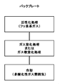
- FIG. 2 is a diagram showing a surface treatment process of the back plate of the present invention.
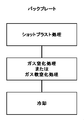
- FIG. 3 is a diagram showing a conventional back plate surface treatment process.
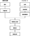
- FIG. 4 is a diagram showing an example of the manufacturing process of the disc brake pad of the present invention.
- FIG. 5 is an observation image of 3000 times the cross section of the back plate of Example 4.
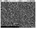
- FIG. 6 is an observation image 1000 times the surface of the back plate of Example 4.
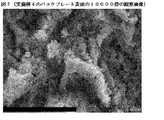
- FIG. 7 is an observation image of 10000 times the back plate surface of Example 4.
- FIG. 8 is an observation image of 3000 times the cross section of the back plate of Comparative Example 3.
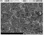
- FIG. 9 is an observation image of 1000 times the back plate surface of Comparative Example 3.
- FIG. 10 is an observation image of 10000 times the back plate surface of Comparative Example 3.
- the disc brake pad is formed by bonding a back plate and a friction material with an adhesive or the like.
- the back plate is formed by sheet metal pressing of a hot rolled steel plate for automobile structure such as SAPH440 or a workable hot rolled high strength steel plate for automobile such as SPFH590.
- a compound layer having a depth of 5 ⁇ m to 20 ⁇ m is formed on the surface to which the friction material of the back plate is bonded by gas nitriding or gas soft nitriding, and the compound layer has a depth of 40 ⁇ m on the surface layer side. % Or more of the porous layer.
- a back plate having a compound layer depth of 5 ⁇ m to 20 ⁇ m and a porous layer thickness of 40% or more of the compound layer depth is used, the adhesive strength between the friction material and the back plate is improved.
- the thickness of the oxide layer formed on the surface layer of the back plate to which the friction material is bonded is too large, the adhesive strength decreases, so the oxide layer formed on the surface layer of the surface to which the friction material is bonded More preferably, a back plate having a thickness of 1 ⁇ m or less is used.
- Such a back plate can be obtained by performing a surface treatment described below.
- the fluorine-based gas used for the activation treatment is a fluorine-based gas (fluorine compound gas or fluorine gas) that is a halogen-based substance having a higher affinity than oxygen for Fe, which is a base material component forming an oxide film. Containing gas).
- fluorine-based gas include a gas mainly containing a fluorine compound, for example, NF 3 , BF 3 , CF 4 , SF 6, and the like, and a gas mainly containing F 2.
- this main component gas is diluted with a diluent gas such as nitrogen gas and used as a fluorine-based gas.
- a diluent gas such as nitrogen gas
- NF 3 is the most excellent in terms of reactivity and handling properties and is practical.
- the back plate is held in the fluorine-based gas atmosphere, for example, in a fluorine-based gas atmosphere containing NF 3 .
- a fluoride film layer capable of forming a porous layer having necessary and sufficient irregularities after nitriding or soft nitriding by setting the treatment temperature in this range to 350 to 450 ° C., preferably in the range of 400 to 450 ° C. can be formed.
- the activation treatment time is set according to the material of the back plate to be treated, with appropriate conditions for fluorination of the surface oxide film and the iron substrate of the back plate under the oxide film.
- the range is 180 minutes.
- the concentration of the fluorine compound or fluorine in the fluorine-based gas atmosphere is preferably 1000 to 100,000 ppm.
- Gas nitriding treatment or gas soft nitriding treatment The gas nitriding treatment carried out after the activation treatment step described above is performed at a treatment temperature of 300 to 600 ° C. in an atmosphere containing ammonia gas as a nitrogen source gas. It is preferably carried out in the range of 400 to 600 ° C. and a treatment time of 30 minutes to 60 minutes.
- gas soft nitriding a mixed gas of ammonia gas and carburizing gas is used as a nitrogen source gas.
- Cooling Step The cooling step performed continuously with the gas nitriding treatment step described above is performed in a non-oxidizing gas atmosphere.
- a non-oxidizing gas ammonia gas, nitrogen gas or the like can be used. If the cooling step is performed in a processing furnace of a gas nitriding process or a gas soft nitriding process, the process of moving to another processing furnace can be omitted, which is efficient.
- Friction material is a metal substrate, organic fiber, fiber base material such as inorganic fiber, binder such as thermosetting resin, and friction adjustment of organic filler, inorganic filler, lubricant, etc. Material.
- the fiber base material examples include metal fibers such as steel fibers and copper fibers, organic fibers such as aramid fibers and acrylic fibers, potassium titanate fibers, carbon fibers, ceramic fibers, and inorganic fibers such as rock wool. Alternatively, two or more kinds can be used in combination.
- thermosetting resins such as phenol resins and epoxy resins, resins obtained by modifying these thermosetting resins with cashew oil, silicone oil, various elastomers, etc., and various elastomers and fluoropolymers to these thermosetting resins. And the like can be used, and these can be used alone or in combination of two or more.
- friction modifiers examples include cashew dust, rubber dust (pulverized tire tread rubber), unvulcanized rubber particles, organic fillers such as vulcanized rubber particles, barium sulfate, calcium carbonate, calcium hydroxide, Examples include inorganic fillers such as vermiculite and mica, and lubricants such as graphite, molybdenum disulfide, tin sulfide, zinc sulfide, and iron sulfide. These can be used alone or in combination of two or more.
- the disc brake pad of the present invention is obtained by adhering a friction material to the back plate surface-treated by the above surface treatment method.
- the disc brake pad of the present invention is subjected to a surface treatment by the above-mentioned surface treatment method, a mixing step in which the fiber base material, the binder, and the friction modifier mixed in a predetermined amount are uniformly mixed using a mixer.
- the back plate coated with the adhesive and the friction material raw material mixture obtained in the mixing process are put into a thermoforming mold and heated and pressed to form, and the resulting molded product is heated.
- it is manufactured through a heat treatment step for completing the curing reaction of the binder and a polishing step for forming a friction surface.
- the friction material raw material mixture put the friction material raw material mixture or the granulated material obtained in the granulation process into a preforming mold, A pre-molding process for molding the molded product is performed, and after the heat and pressure molding process, a coating, a paint baking process, and a scorch process are performed.
- ⁇ Back plate of Example 1> The back plate made of the cleaned SAPH440 was put into a furnace maintained at an atmospheric temperature of 350 ° C., and NF 3 gas was introduced into the furnace and maintained for 30 minutes for activation treatment. Then, after heating up to 570 degreeC, ammonia gas was introduce
- ⁇ Back plate of Example 2> The back plate made of the washed SAPH440 was put into a furnace maintained at an ambient temperature of 400 ° C., and NF 3 gas was introduced into the furnace and maintained for 30 minutes for activation treatment. Then, after heating up to 570 degreeC, ammonia gas was introduce
- ⁇ Back plate of Example 3> The back plate made of the cleaned SAPH440 was put into a furnace maintained at an atmospheric temperature of 450 ° C., and NF 3 gas was introduced into the furnace and maintained for 30 minutes for activation treatment. Then, after heating up to 570 degreeC, ammonia gas was introduce
- ⁇ Back plate of Example 4> The back plate made of the washed SAPH440 was put into a furnace maintained at an ambient temperature of 400 ° C., and NF 3 gas was introduced into the furnace and maintained for 30 minutes for activation treatment. Then, after heating up to 570 degreeC, ammonia gas was introduce
- ⁇ Back plate of Example 5> The back plate made of the cleaned SAPH440 was put into a furnace maintained at an atmospheric temperature of 350 ° C., and NF 3 gas was introduced into the furnace and maintained for 30 minutes for activation treatment. Then, after heating up to 570 degreeC, ammonia gas was introduce
- ⁇ Back plate of Comparative Example 1> The back plate made of the cleaned SAPH440 was put into a furnace maintained at an atmospheric temperature of 300 ° C., and NF 3 gas was introduced into the furnace and maintained for 30 minutes for activation treatment. Then, after heating up to 570 degreeC, ammonia gas was introduce
- ⁇ Back plate of Comparative Example 2> The back plate made of the cleaned SAPH440 was put into a furnace maintained at an atmospheric temperature of 500 ° C., and NF 3 gas was introduced into the furnace and maintained for 30 minutes for activation treatment. Then, after heating up to 570 degreeC, ammonia gas was introduce
- FIG. 5 which is an observation image of the cross section of the back plate of Example 4
- FIG. 8 which is an observation image of the cross section of the back plate of the comparative example
- the porous layer of Example 4 is formed deeper than Comparative Example 3. You can see that.
- the depth of the compound layer formed on the back plate of Example 4 is about 13 ⁇ m, the thickness of the porous layer is about 8 ⁇ m, and the thickness of the porous layer is about 61% of the depth of the compound layer.
Landscapes
- Chemical & Material Sciences (AREA)
- Engineering & Computer Science (AREA)
- Mechanical Engineering (AREA)
- General Engineering & Computer Science (AREA)
- Chemical Kinetics & Catalysis (AREA)
- Materials Engineering (AREA)
- Metallurgy (AREA)
- Organic Chemistry (AREA)
- Braking Arrangements (AREA)
- Solid-Phase Diffusion Into Metallic Material Surfaces (AREA)
Abstract
[課題] 自動車等のディスクブレーキパッドに使用される、鋼製のバックプレート及びそのバックプレートを用いたディスクブレーキパッドであって、摩擦材とバックプレートの接着強度を向上できるバックプレート、及び、そのバックプレートに摩擦材を接着した、充分な接着強度を有するディスクブレーキパッドを提供すること。 [解決手段] ディスクブレーキパッド用の鋼製のバックプレートとして、摩擦材を接着する面にガス窒化法またはガス軟窒化法により形成した深さ5μm~20μmの化合物層と、前記化合物層の表層側に前記化合物層の深さの40%以上の厚みのポーラス層を有すると共に、表層に形成される酸化物層の厚さが1μm以下であるバックプレートを使用する。
Description
本発明は、自動車等のディスクブレーキパッドに使用される、鋼製のバックプレート及び、そのバックプレートに摩擦材を接着したディスクブレーキパッドに関する。
自動車のディスクブレーキに使用されているディスクブレーキパッドは、バックプレートと呼ばれる自動車構造用熱間圧延鋼板などの鋼材からなるベース部材に、繊維基材、結合材、摩擦調整材からなる摩擦材を、接着剤や摩擦材に含まれる結合材により接着したものである。
ディスクブレーキは、車輪と共に回転するディスクローターを挟むようにディスクブレーキパッドが配置されており、そのディスクブレーキパッドをディスクローターに押圧して摩擦させることにより制動力を得ている。
このときにディスクブレーキパッドの摩擦材とバックプレートの間には大きなせん断力が加わるため、摩擦材とバックプレートとの間には、そのせん断力に耐え得る接着強度が必要とされている。
摩擦材とバックプレートの接着強度を向上させるため、バックプレートの表面に微細な凹凸を持つポーラス層を形成させる方法が知られている。
バックプレートの表面に微細な凹凸を持つポーラス層があると、接着剤や、摩擦材に含まれる結合材が凹凸に入り込み、そのアンカー効果により摩擦材とバックプレートの接着強度が向上する。
バックプレートの表面に微細な凹凸を持つポーラス層があると、接着剤や、摩擦材に含まれる結合材が凹凸に入り込み、そのアンカー効果により摩擦材とバックプレートの接着強度が向上する。
摩擦材を接着する前のバックプレートの表面に施される前処理として窒化処理法または軟窒化処理法が採用されている。
窒化処理または軟窒化処理は通常、金属材料表面の耐磨耗性、耐疲労性、耐腐食性、耐熱性を向上させるために実施されるものであり、材料の表面は平滑に仕上げられることが一般的である。
しかし、当該技術分野において窒化処理または軟窒化処理は、バックプレートの表面に微細な凹凸を持つポーラス層を有する化合物層を形成する手段として採用されており、その目的、効果ともに一般的な他の技術分野と比べて特異である。
特公昭53-47218号公報(特許文献1)には、鉄系材料からなるバックプレートの表面に、表面粗さが5~50μmのこぶ状ないし網目状の微細な突起をもった表面状態を呈するFe-C-N系を主体とする化合物層が層厚5μm以上形成し、該化合物層表面に接着剤を介して摩擦材を接着することにより、摩擦材とバックプレートの間の接着力を高めたディスクブレーキパッドが記載されている。
このようなバックプレートのこぶ状ないし網目状の微細な突起を持った表面を有する化合物層は、アンモニアガスを使用したガス軟窒化法、ガス軟窒化法や、シアン化合物を使用した塩浴窒化法、塩浴軟窒化法により形成することができる。
特開2007-64431号公報(特許文献2)には、バックプレートをショットブラストにより粗面にした後、軟窒化皮膜処理を施すディスクブレーキパッドの製造方法が記載されている。
しかし、塩浴窒化法、塩浴軟窒化法はシアン化合物を使用するため、環境面の観点から好ましくないという問題があり、また、ガス窒化法やガス軟窒化法では、充分な厚みのポーラス層を形成することができないため、近年の自動車の高出力化により高まってきている接着強度に関する要求性能を満たせなくなってきている。
また、ショットブラスト処理は、表面を粗面化すること及び、窒化処理または軟窒化処理による化合物層の形成を阻害する酸化物層を除去することを目的として実施されるが、同時にバックプレートの端部にバリが形成されるという問題がある。このバリは、ブレーキの振動特性に悪影響を与えるため除去する必要があり、その工程を設けなければならないため非効率である。
一方で、金属材料の窒化処理法として、特開平3-44457号公報(特許文献3)のような、金属材料の表面に存在する酸化膜をフッ素系ガスによりフッ化膜に置換し、金属材料の表面を活性化させる活性化処理を行った後、アンモニアガスにより、金属材料の表面に化合物層を形成する窒化処理法が知られている。
特許文献3に記載の窒化処理法は、ショットブラスト処理などの金属材料の表面を変形させるような方法を使用することなく金属材料の表面に存在する酸化膜を除去することが可能なため、緻密で平滑な化合物層表面を得る必要がある技術分野において広く使用されている。
しかし、特許文献3に記載の窒化処理法は、摩擦材とバックプレートのせん断強度を得るためにバックプレートの表面に微細な凹凸を持つポーラス層を有する化合物層を形成させる必要がある当該技術分野においては、これまで着目されることがなく、技術的な検討が一切なされていなかった。
本発明は上記事情に鑑みなされたもので、自動車等のディスクブレーキパッドに使用される、鋼製のバックプレート及び、そのバックプレートを用いたディスクブレーキパッドであって、摩擦材とバックプレートの接着強度を向上できるバックプレート及び、そのバックプレートに摩擦材を接着した、充分な接着強度を有するディスクブレーキパッドを提供することを課題とする。
摩擦材とバックプレートの接着強度をより向上させるためには、充分な厚みを持つポーラス層を有する化合物層を形成したバックプレートを用いる必要がある。
本発明者らは、前述したように、当該技術分野では技術的な検討が一切なされていなかった、金属材料の表面に存在する酸化膜をフッ素系ガスによりフッ化膜に置換し、金属材料の表面を活性化させる活性化処理を行った後、アンモニアガスにより、金属材料の表面に化合物層を形成する窒化処理法に着目し、鋭意検討を行った。
バックプレートとして使用されるSAPH400、SAPH440等の自動車構造用熱間圧延鋼板、SPFH590等の自動車用加工性熱間圧延高張力鋼板において、フッ素ガスによる活性化処理は通常、その表面を平滑に仕上げるため150~350℃の処理温度で実施されている。
しかし、この処理温度を通常の温度よりも高くすると、バックプレート表面の酸化膜だけではなく、酸化膜の下にあるバックプレートの鉄素地もフッ化され、その状態で、ガス窒化処理またはガス軟窒化処理を施すと、驚くべきことに従来の当該技術分野で実施されていたガス窒化法、ガス軟窒化法では得られなかった、充分な厚みを持つポーラス層を有する化合物層を形成したバックプレートを製作することが可能となった。そのバックプレートに摩擦材を接着したディスクブレーキパッドは接着強度が飛躍的に向上することを知見し、本発明を完成させるに至った。
また、バックプレートのガス窒化処理またはガス軟窒化処理の後に実施する冷却工程を、ガス窒化処理工程またはガス軟窒化工程と連続して非酸化性ガス雰囲気下で行うことにより、接着剤の密着性を阻害する原因となる酸化膜の再形成を抑制することができ、接着強度がより向上することをさらに知見した。
本発明は、自動車等のディスクブレーキパッドに使用される、自動車構造用熱間圧延鋼板製等のバックプレート及び、そのバックプレートを用いたディスクブレーキパッドに関し、摩擦材とバックプレートの接着強度を向上できるバックプレート及び、そのバックプレートに摩擦材を貼り付けた、充分な接着強度を有するディスクブレーキパッドであり、以下の技術を基礎とするものである。
(1)ディスクブレーキパッド用の鋼製のバックプレートにおいて、摩擦材を接着する面にガス窒化法またはガス軟窒化法により形成された深さ5μm~20μmの化合物層を有し、かつ、前記化合物層は表層側に前記化合物層の深さの40%以上の厚みのポーラス層を有することを特徴とするバックプレート。
(2)摩擦材を接着する面の表層に形成される酸化物層の厚さが1μm以下であることを特徴とする(1)に記載のバックプレート。
(3)(1)または(2)に記載のバックプレートに、摩擦材を接着してなるディスクブレーキパッド。
本発明によれば、摩擦材とバックプレートの接着強度を向上できる表面処理を施したバックプレートと、充分な接着強度を有するディスクブレーキパッドを提供することができる。
(1)ディスクブレーキパッド
図1に示すように、ディスクブレーキパッドはバックプレートと摩擦材を接着剤等により接着してなる。
図1に示すように、ディスクブレーキパッドはバックプレートと摩擦材を接着剤等により接着してなる。
(1-1)バックプレート
バックプレートは、SAPH440等の自動車構造用熱間圧延鋼板やSPFH590等の自動車用加工性熱間圧延高張力鋼板を板金プレス加工で以って成形したものである。
バックプレートは、SAPH440等の自動車構造用熱間圧延鋼板やSPFH590等の自動車用加工性熱間圧延高張力鋼板を板金プレス加工で以って成形したものである。
バックプレートの摩擦材を接着する面には、ガス窒化法またはガス軟窒化法により深さ5μm~20μmの化合物層が形成されており、前記化合物層は表層側に前記化合物層の深さの40%以上の厚みのポーラス層を有する。
化合物層の深さが5μm~20μmであり、ポーラス層の厚みが化合物層の深さの40%以上であるバックプレートを使用すれば、摩擦材とバックプレートの接着強度が向上する。接着強度をより向上させるため、ポーラス層の厚みが化合物層の深さの50%以上90%以下であるバックプレートを使用するのが好ましく、ポーラス層の厚みが化合物層の深さの60%以上80%以下であるバックプレートを使用するのがより好ましい。
また、バックプレートの摩擦材を接着する面の表層に形成される酸化物層の厚みが大きすぎると、接着強度が低下するため、摩擦材を接着する面の表層に形成される酸化物層の厚さが1μm以下のバックプレートを使用するのが更に好ましい。
このようなバックプレートは、以下に説明する表面処理を施すことにより得ることができる。
(1-1)バックプレートの表面処理
(1-1-1)活性化処理
活性化処理工程は、フッ素系ガスを含む雰囲気にバックプレートを投入して、バックプレート表面に形成している酸化膜及び酸化膜の下にあるバックプレートの鉄素地をフッ化させ、フッ化膜を形成させる。
(1-1-1)活性化処理
活性化処理工程は、フッ素系ガスを含む雰囲気にバックプレートを投入して、バックプレート表面に形成している酸化膜及び酸化膜の下にあるバックプレートの鉄素地をフッ化させ、フッ化膜を形成させる。
活性化処理に使用するフッ素系ガスとしては、酸化膜を形成している母材成分であるFeに対して酸素よりも親和性が強いハロゲン系物質であるフッ素系ガス(フッ素化合物ガスまたはフッ素ガスを含有するガス)が用いられる。このフッ素系ガスとしては、フッ素化合物、例えばNF3、BF3、CF4、SF6などを主成分とするガスやF2を主成分とするガスがあげられる。
通常は、この主成分ガスを窒素ガスなどの希釈ガスで希釈してフッ素系ガスとして使用する。これらのフッ素系ガスに用いられる主成分ガスのうち、反応性、取り扱い性などの面でNF3が最も優れており、実用的である。
上記フッ素系ガス雰囲気でバックプレートを、例えばNF3を含むフッ素系ガス雰囲気中で保持する。このときの処理温度を350~450℃の範囲、好ましくは400~450℃の範囲とすることにより、窒化処理または軟窒化処理後に必要充分な凹凸を持つポーラス層を形成し得るフッ化膜の層を形成させることができる。
なお、活性化処理の時間については処理を行なうバックプレートの材質に応じて、表面の酸化膜及び酸化膜下のバックプレートの鉄素地がフッ化する適当な条件を設定するが、通常は10~180分の範囲である。
また、フッ素系ガス雰囲気のフッ素化合物またはフッ素の濃度は、1000~100000ppmとするのが好ましい。
(1-1-2)ガス窒化処理またはガス軟窒化処理
上述した活性化処理工程に引き続き実施されるガス窒化処理については、窒素源ガスとしてアンモニアガスを含む雰囲気中で、処理温度300~600℃、好ましくは400~600℃の範囲、処理時間30分~60分で実施する。
ガス軟窒化処理の場合は、窒素源ガスとしてのアンモニアガスと浸炭性ガスの混合ガスを使用する。
上述した活性化処理工程に引き続き実施されるガス窒化処理については、窒素源ガスとしてアンモニアガスを含む雰囲気中で、処理温度300~600℃、好ましくは400~600℃の範囲、処理時間30分~60分で実施する。
ガス軟窒化処理の場合は、窒素源ガスとしてのアンモニアガスと浸炭性ガスの混合ガスを使用する。
(1-1-3)冷却工程
上述したガス窒化処理工程と連続して実施される冷却工程については、非酸化性ガス雰囲気下で行われる。非酸化性ガスとしてはアンモニアガス、窒素ガスなどが使用できる。冷却工程は、ガス窒化処理工程またはガス軟窒化処理工程の処理炉で行えば、別の処理炉に移動させる工程を省くことができ、効率的である。
上述したガス窒化処理工程と連続して実施される冷却工程については、非酸化性ガス雰囲気下で行われる。非酸化性ガスとしてはアンモニアガス、窒素ガスなどが使用できる。冷却工程は、ガス窒化処理工程またはガス軟窒化処理工程の処理炉で行えば、別の処理炉に移動させる工程を省くことができ、効率的である。
(1-2)摩擦材
摩擦材は、金属繊維、有機繊維と、無機繊維などの繊維基材、熱硬化性樹脂などの結合材と、有機充填材、無機充填材、潤滑剤などの摩擦調整材とを含んでなる。
摩擦材は、金属繊維、有機繊維と、無機繊維などの繊維基材、熱硬化性樹脂などの結合材と、有機充填材、無機充填材、潤滑剤などの摩擦調整材とを含んでなる。
繊維基材としては、スチール繊維、銅繊維等の金属繊維、アラミド繊維、アクリル繊維等の有機繊維、チタン酸カリウム繊維、カーボン繊維、セラミック繊維、ロックウール等の無機繊維が挙げられ、これらを単独又は2種以上を組み合わせて使用することができる。
結合材としては、フェノール樹脂、エポキシ樹脂などの熱硬化性樹脂、これらの熱硬化性樹脂をカシューオイル、シリコーンオイル、各種エラストマー等で変性した樹脂、これらの熱硬化性樹脂に各種エラストマー、フッ素ポリマー等を分散させた樹脂等が挙げられ、これらを単独で又は2種以上を組み合わせて使用することができる。
摩擦調整材としては、カシューダスト、ゴムダスト(タイヤトレッドゴムの粉砕粉)、未加硫の各種ゴム粒子、加硫された各種ゴム粒子等の有機充填材、硫酸バリウム、炭酸カルシウム、水酸化カルシウム、バーミキュライト、マイカ等の無機充填材、グラファイト、二硫化モリブデン、硫化錫、硫化亜鉛、硫化鉄等の潤滑剤が挙げられ、これらを単独で又は2種以上を組み合わせて使用することができる。
(1-3)ディスクブレーキパッドの製造方法
本発明のディスクブレーキパッドは、上記の表面処理方法で表面処理したバックプレートに、摩擦材を接着したものである。
本発明のディスクブレーキパッドは、上記の表面処理方法で表面処理したバックプレートに、摩擦材を接着したものである。
本発明のディスクブレーキパッドは、所定量配合した上記繊維基材、結合材、摩擦調整材を、混合機を用いて均一に混合する混合工程、上記の表面処理方法で表面処理し、必要に応じて接着剤を塗布したバックプレートと、混合工程で得られた摩擦材原料混合物とを重ねて熱成形型に投入し、加熱加圧して成形する加熱加圧成形工程、得られた成形品を加熱して結合材の硬化反応を完了させる熱処理工程、摩擦面を形成する研磨処理工程を経て製造される。
必要に応じて、加熱加圧成形工程の前に、摩擦材原料混合物を造粒する造粒工程、摩擦材原料混合物または造粒工程で得られた造粒物を予備成形型に投入し、予備成形物を成形する予備成形工程が実施され、加熱加圧成形工程の後に、塗装、塗装焼き付け工程、スコーチ工程が実施される。
以下、実施例に基づき、本発明を説明するが、本発明は下記の実施例に制限されるものではない。
<実施例1~5及び比較例1~3>
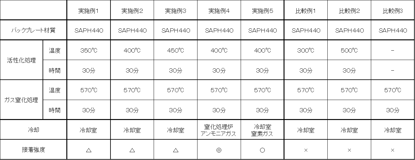
表1に示す条件で、バックプレートの表面処理を行った。各実施例、比較例の具体的な表面処理方法は、以下に詳述する。
表1に示す条件で、バックプレートの表面処理を行った。各実施例、比較例の具体的な表面処理方法は、以下に詳述する。
〈実施例1のバックプレート〉
洗浄処理したSAPH440からなるバックプレートを、雰囲気温度350℃に保持された炉内に投入し、NF3ガスを炉内に導入し30分間保持して活性化処理を行った。
その後、570℃に昇温した後、アンモニアガスを炉内に導入し30分間保持して窒化処理を行った。更に、冷却室に移動させ、室温まで冷却させ、表面処理されたバックプレートを得た。
洗浄処理したSAPH440からなるバックプレートを、雰囲気温度350℃に保持された炉内に投入し、NF3ガスを炉内に導入し30分間保持して活性化処理を行った。
その後、570℃に昇温した後、アンモニアガスを炉内に導入し30分間保持して窒化処理を行った。更に、冷却室に移動させ、室温まで冷却させ、表面処理されたバックプレートを得た。
〈実施例2のバックプレート〉
洗浄処理したSAPH440からなるバックプレートを、雰囲気温度400℃に保持された炉内に投入し、NF3ガスを炉内に導入し30分間保持して活性化処理を行った。
その後、570℃に昇温した後、アンモニアガスを炉内に導入し30分間保持して窒化処理を行った。更に、冷却室に移動させ、室温まで冷却させ、表面処理されたバックプレートを得た。
洗浄処理したSAPH440からなるバックプレートを、雰囲気温度400℃に保持された炉内に投入し、NF3ガスを炉内に導入し30分間保持して活性化処理を行った。
その後、570℃に昇温した後、アンモニアガスを炉内に導入し30分間保持して窒化処理を行った。更に、冷却室に移動させ、室温まで冷却させ、表面処理されたバックプレートを得た。
〈実施例3のバックプレート〉
洗浄処理したSAPH440からなるバックプレートを、雰囲気温度450℃に保持された炉内に投入し、NF3ガスを炉内に導入し30分間保持して活性化処理を行った。
その後、570℃に昇温した後、アンモニアガスを炉内に導入し30分間保持して窒化処理を行った。更に、冷却室に移動させ、室温まで冷却させ、表面処理されたバックプレートを得た。
洗浄処理したSAPH440からなるバックプレートを、雰囲気温度450℃に保持された炉内に投入し、NF3ガスを炉内に導入し30分間保持して活性化処理を行った。
その後、570℃に昇温した後、アンモニアガスを炉内に導入し30分間保持して窒化処理を行った。更に、冷却室に移動させ、室温まで冷却させ、表面処理されたバックプレートを得た。
〈実施例4のバックプレート〉
洗浄処理したSAPH440からなるバックプレートを、雰囲気温度400℃に保持された炉内に投入し、NF3ガスを炉内に導入し30分間保持して活性化処理を行った。
その後、570℃に昇温した後、アンモニアガスを炉内に導入し30分間保持して窒化処理を行った。更に、そのままアンモニアガスを充満させた炉内で室温まで冷却させ、表面処理されたバックプレートを得た。
洗浄処理したSAPH440からなるバックプレートを、雰囲気温度400℃に保持された炉内に投入し、NF3ガスを炉内に導入し30分間保持して活性化処理を行った。
その後、570℃に昇温した後、アンモニアガスを炉内に導入し30分間保持して窒化処理を行った。更に、そのままアンモニアガスを充満させた炉内で室温まで冷却させ、表面処理されたバックプレートを得た。
〈実施例5のバックプレート〉
洗浄処理したSAPH440からなるバックプレートを、雰囲気温度350℃に保持された炉内に投入し、NF3ガスを炉内に導入し30分間保持して活性化処理を行った。
その後、570℃に昇温した後、アンモニアガスを炉内に導入し30分間保持して窒化処理を行った。更に、冷却室に移動させ、窒素ガスを導入して室温まで冷却させ、表面処理されたバックプレートを得た。
洗浄処理したSAPH440からなるバックプレートを、雰囲気温度350℃に保持された炉内に投入し、NF3ガスを炉内に導入し30分間保持して活性化処理を行った。
その後、570℃に昇温した後、アンモニアガスを炉内に導入し30分間保持して窒化処理を行った。更に、冷却室に移動させ、窒素ガスを導入して室温まで冷却させ、表面処理されたバックプレートを得た。
〈比較例1のバックプレート〉
洗浄処理したSAPH440からなるバックプレートを、雰囲気温度300℃に保持された炉内に投入し、NF3ガスを炉内に導入し30分間保持して活性化処理を行った。
その後、570℃に昇温した後、アンモニアガスを炉内に導入し30分間保持して窒化処理を行った。更に、冷却室に移動させ、室温まで冷却させ、表面処理されたバックプレートを得た。
洗浄処理したSAPH440からなるバックプレートを、雰囲気温度300℃に保持された炉内に投入し、NF3ガスを炉内に導入し30分間保持して活性化処理を行った。
その後、570℃に昇温した後、アンモニアガスを炉内に導入し30分間保持して窒化処理を行った。更に、冷却室に移動させ、室温まで冷却させ、表面処理されたバックプレートを得た。
〈比較例2のバックプレート〉
洗浄処理したSAPH440からなるバックプレートを、雰囲気温度500℃に保持された炉内に投入し、NF3ガスを炉内に導入し30分間保持して活性化処理を行った。
その後、570℃に昇温した後、アンモニアガスを炉内に導入し30分間保持して窒化処理を行った。更に、冷却室に移動させ、室温まで冷却させ、表面処理されたバックプレートを得た。
洗浄処理したSAPH440からなるバックプレートを、雰囲気温度500℃に保持された炉内に投入し、NF3ガスを炉内に導入し30分間保持して活性化処理を行った。
その後、570℃に昇温した後、アンモニアガスを炉内に導入し30分間保持して窒化処理を行った。更に、冷却室に移動させ、室温まで冷却させ、表面処理されたバックプレートを得た。
〈比較例3のバックプレート〉
洗浄処理したSAPH440からなるバックプレートを、570℃に保持された炉内に投入し、アンモニアガスを炉内に導入し30分間保持して窒化処理を行った。
さらに、冷却室に移動させ、室温まで冷却させ、表面処理されたバックプレートを得た。
洗浄処理したSAPH440からなるバックプレートを、570℃に保持された炉内に投入し、アンモニアガスを炉内に導入し30分間保持して窒化処理を行った。
さらに、冷却室に移動させ、室温まで冷却させ、表面処理されたバックプレートを得た。
〈実施例1~5、比較例1~3のディスクブレーキパッドの製造方法〉
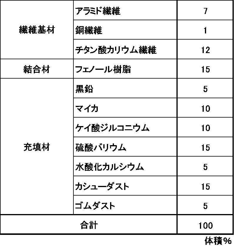
表2に示す組成の摩擦材原料を混合機で5分間混合し、得られた摩擦材原料混合物を、予備成形金型で10MPaにて1分加圧して予備成形を行った。
この予備成形物と、接着剤を塗布した実施例1~5、比較例1~2のバックプレートを重ねて熱成形金型に投入し、成形温度150℃、成形圧力40MPaの条件下で10分間成形した。
その後、200℃で5時間熱処理(後硬化)を行い、研磨して実施例1~5、比較例1~2のディスクブレーキパッドを作製した。
表2に示す組成の摩擦材原料を混合機で5分間混合し、得られた摩擦材原料混合物を、予備成形金型で10MPaにて1分加圧して予備成形を行った。
この予備成形物と、接着剤を塗布した実施例1~5、比較例1~2のバックプレートを重ねて熱成形金型に投入し、成形温度150℃、成形圧力40MPaの条件下で10分間成形した。
その後、200℃で5時間熱処理(後硬化)を行い、研磨して実施例1~5、比較例1~2のディスクブレーキパッドを作製した。
〈接着強度の評価〉
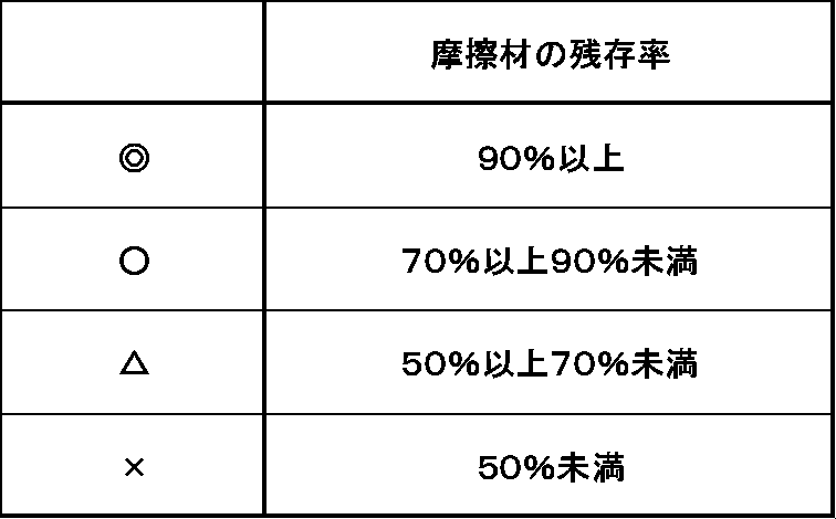
摩擦材とバックプレートの接着強度は、JIS D4422(自動車部品―ブレーキシューアッセンブリ及びディスクブレーキパッド―せん断試験方法)に準拠し、ディスクブレーキパッドを300℃の雰囲気で36時間保持した後、せん断試験を行い、バックプレート上に残存する摩擦材の残存率を用いて評価した。評価基準は表3のとおりである。評価結果は表1に併記してある。
摩擦材とバックプレートの接着強度は、JIS D4422(自動車部品―ブレーキシューアッセンブリ及びディスクブレーキパッド―せん断試験方法)に準拠し、ディスクブレーキパッドを300℃の雰囲気で36時間保持した後、せん断試験を行い、バックプレート上に残存する摩擦材の残存率を用いて評価した。評価基準は表3のとおりである。評価結果は表1に併記してある。
〈バックプレート断面および表面の観察〉
電子顕微鏡を用いて実施例4と比較例3のバックプレートの断面を3000倍の倍率で、バックプレートの表面を1000倍、10000倍の倍率で観察した。それぞれの観察画像を図5~図10に示す。
電子顕微鏡を用いて実施例4と比較例3のバックプレートの断面を3000倍の倍率で、バックプレートの表面を1000倍、10000倍の倍率で観察した。それぞれの観察画像を図5~図10に示す。
実施例4のバックプレートの断面の観察画像である図5と、比較例のバックプレートの断面の観察画像である図8を比較すると、比較例3よりも実施例4のポーラス層がより深く形成されていることが分かる。
実施例4のバックプレートに形成された化合物層の深さは約13μm、ポーラス層の厚さは約8μmであり、ポーラス層の厚みは化合物層の深さの約61%である。
比較例3のバックプレートに形成された化合物層の厚さは約13μm、ポーラス層の厚さは約5μmであり、ポーラス層の厚みは化合物層の深さの約38%である。
また、実施例4のバックプレートの表面の観察画像である図6、図7と、比較例3のバックプレートの観察画像である図9、図10を比較すると、比較例3よりも実施例4の凹凸パターンがより緻密で複雑な皺状を呈していることが分かる。
自動車等のディスクブレーキパッドに使用される、鋼製のバックプレートにおいて、摩擦材とバックプレートの接着強度を向上させることができ、
充分な接着強度を有するディスクブレーキパッドを得ることができ、自動車工業のさらなる発展に寄与するものである。
充分な接着強度を有するディスクブレーキパッドを得ることができ、自動車工業のさらなる発展に寄与するものである。
1 ディスクブレーキパッド
2 バックプレート
3 摩擦材
2 バックプレート
3 摩擦材
Claims (3)
- ディスクブレーキパッド用の鋼製のバックプレートにおいて、摩擦材を接着する面にガス窒化法またはガス軟窒化法により形成された深さ5μm~20μmの化合物層を有し、かつ、前記化合物層は表層側に前記化合物層の深さの40%以上の厚みのポーラス層を有することを特徴とするバックプレート。
- 摩擦材を接着する面の表層に形成される酸化物層の厚さが1μm以下であることを特徴とする請求項1に記載のバックプレート。
- 請求項1または2に記載のバックプレートに、摩擦材を接着してなるディスクブレーキパッド。
Priority Applications (3)
| Application Number | Priority Date | Filing Date | Title |
|---|---|---|---|
| US14/122,666 US20140209422A1 (en) | 2011-06-03 | 2012-05-29 | Back plate for disc brake pad and disc brake pad using the back plate |
| EP12793146.7A EP2716789B1 (en) | 2011-06-03 | 2012-05-29 | Backing plate for disk brake pad, and disk brake pad utilizing backing plate |
| CN201280027113.XA CN103597112A (zh) | 2011-06-03 | 2012-05-29 | 盘式制动器垫用制动底板和使用了该制动底板的盘式制动器垫 |
Applications Claiming Priority (2)
| Application Number | Priority Date | Filing Date | Title |
|---|---|---|---|
| JP2011-125048 | 2011-06-03 | ||
| JP2011125048A JP6125143B2 (ja) | 2011-06-03 | 2011-06-03 | ディスクブレーキパッド用バックプレート及び、そのバックプレートを用いたディスクブレーキパッド |
Publications (1)
| Publication Number | Publication Date |
|---|---|
| WO2012164911A1 true WO2012164911A1 (ja) | 2012-12-06 |
Family
ID=47258786
Family Applications (1)
| Application Number | Title | Priority Date | Filing Date |
|---|---|---|---|
| PCT/JP2012/003503 Ceased WO2012164911A1 (ja) | 2011-06-03 | 2012-05-29 | ディスクブレーキパッド用バックプレート及び、そのバックプレートを用いたディスクブレーキパッド |
Country Status (6)
| Country | Link |
|---|---|
| US (1) | US20140209422A1 (ja) |
| EP (1) | EP2716789B1 (ja) |
| JP (1) | JP6125143B2 (ja) |
| KR (1) | KR101955037B1 (ja) |
| CN (1) | CN103597112A (ja) |
| WO (1) | WO2012164911A1 (ja) |
Cited By (1)
| Publication number | Priority date | Publication date | Assignee | Title |
|---|---|---|---|---|
| CN103992769A (zh) * | 2014-05-05 | 2014-08-20 | 浙江杭摩欧亿汽车零部件有限公司 | 一种轿车用无铜高性能环保型摩擦材料及制备方法 |
Families Citing this family (8)
| Publication number | Priority date | Publication date | Assignee | Title |
|---|---|---|---|---|
| JP6234803B2 (ja) * | 2013-12-18 | 2017-11-22 | 曙ブレーキ工業株式会社 | プレッシャプレートおよびこれを用いたブレーキパッド、並びにこれらの製造方法 |
| DE102014012142A1 (de) * | 2014-08-14 | 2016-02-18 | Sfs Intec Holding Ag | Bohrschraube |
| CN104315043A (zh) * | 2014-08-18 | 2015-01-28 | 安徽惠明机械制造有限公司 | 一种轿车用刹车盘 |
| DE102014119492A1 (de) * | 2014-12-23 | 2016-06-23 | Knorr-Bremse Systeme für Schienenfahrzeuge GmbH | Bremsbelaghalterung, Bremsbelag und Belaghalter |
| US20180209501A1 (en) * | 2015-05-07 | 2018-07-26 | Itt Italia S.R.L. | Methods for the preparation of a friction material and for the manufacturing of a brake pad using such friction material and associated brake pad |
| ITTO20150242A1 (it) * | 2015-05-07 | 2016-11-07 | Itt Italia Srl | Metodi per la preparazione di un materiale di attrito e per la fabbricazione di una pastiglia freno utilizzante tale materiale di attrito |
| DE112019002464T5 (de) * | 2018-05-16 | 2021-01-28 | Tenneco Inc. | Bremsbelagträgerplatte |
| CN113638021A (zh) * | 2021-08-27 | 2021-11-12 | 济南金麒麟刹车系统有限公司 | 一种刹车片的防锈方法及通过该方法制得的刹车片 |
Citations (7)
| Publication number | Priority date | Publication date | Assignee | Title |
|---|---|---|---|---|
| JPS5124533A (ja) * | 1974-08-26 | 1976-02-27 | Toyo Kogyo Co | Deisukubureekyoshuu |
| JPS5347218A (en) | 1976-10-12 | 1978-04-27 | Fujitsu Ltd | Orientating device for fault spot |
| JPH0344457A (ja) | 1989-07-10 | 1991-02-26 | Daido Sanso Kk | 鋼の窒化方法 |
| JPH05118362A (ja) * | 1991-10-28 | 1993-05-14 | Toyota Motor Corp | デイスクブレーキ用ブレーキパツド |
| JPH07109362A (ja) * | 1993-10-14 | 1995-04-25 | Aisin Chem Co Ltd | 摩擦部材 |
| JPH11286787A (ja) * | 1998-04-06 | 1999-10-19 | Nisshinbo Ind Inc | 摩擦材用バックプレートの表面処理方法 |
| JP2007064431A (ja) | 2005-09-01 | 2007-03-15 | Akebono Brake Ind Co Ltd | 摩擦材の接着方法 |
Family Cites Families (11)
| Publication number | Priority date | Publication date | Assignee | Title |
|---|---|---|---|---|
| JPS62261726A (ja) * | 1986-05-07 | 1987-11-13 | Aisin Chem Co Ltd | 摩擦材用シユ− |
| JP2501925B2 (ja) * | 1989-12-22 | 1996-05-29 | 大同ほくさん株式会社 | 金属材の前処理方法 |
| JPH08165557A (ja) * | 1994-12-13 | 1996-06-25 | Sumitomo Metal Ind Ltd | 耐ピッチング性軟窒化歯車の製造方法 |
| US6488131B2 (en) * | 2001-01-23 | 2002-12-03 | Meritor Heavy Vehicle Technology, Llc | Disc brake friction lining assembly |
| WO2003071154A1 (en) * | 2002-02-19 | 2003-08-28 | Freni Brembo S.P.A. | Pad for calipers of disk brakes |
| US20050161297A1 (en) * | 2004-01-23 | 2005-07-28 | Innovative Technologies, Llc | Brake pad backing plate and method of making the same |
| US8302745B2 (en) * | 2006-12-20 | 2012-11-06 | Honeywell International Inc. | Backing plate and method of making |
| US8008534B2 (en) * | 2008-06-30 | 2011-08-30 | Uop Llc | Liquid phase hydroprocessing with temperature management |
| KR100924275B1 (ko) * | 2008-10-21 | 2009-10-30 | 고건우 | 브레이크 디스크의 제조방법 |
| ES2731643T3 (es) * | 2009-01-16 | 2019-11-18 | Nippon Steel Corp | Acero para endurecimiento de superficies para uso estructural en máquinas y componente para uso estructural en máquinas |
| CN101555919B (zh) * | 2009-01-25 | 2014-08-13 | 瑞阳汽车零部件(仙桃)有限公司 | 高效陶瓷刹车片 |
-
2011
- 2011-06-03 JP JP2011125048A patent/JP6125143B2/ja active Active
-
2012
- 2012-05-29 WO PCT/JP2012/003503 patent/WO2012164911A1/ja not_active Ceased
- 2012-05-29 EP EP12793146.7A patent/EP2716789B1/en active Active
- 2012-05-29 CN CN201280027113.XA patent/CN103597112A/zh active Pending
- 2012-05-29 US US14/122,666 patent/US20140209422A1/en not_active Abandoned
- 2012-05-31 KR KR1020120058735A patent/KR101955037B1/ko active Active
Patent Citations (7)
| Publication number | Priority date | Publication date | Assignee | Title |
|---|---|---|---|---|
| JPS5124533A (ja) * | 1974-08-26 | 1976-02-27 | Toyo Kogyo Co | Deisukubureekyoshuu |
| JPS5347218A (en) | 1976-10-12 | 1978-04-27 | Fujitsu Ltd | Orientating device for fault spot |
| JPH0344457A (ja) | 1989-07-10 | 1991-02-26 | Daido Sanso Kk | 鋼の窒化方法 |
| JPH05118362A (ja) * | 1991-10-28 | 1993-05-14 | Toyota Motor Corp | デイスクブレーキ用ブレーキパツド |
| JPH07109362A (ja) * | 1993-10-14 | 1995-04-25 | Aisin Chem Co Ltd | 摩擦部材 |
| JPH11286787A (ja) * | 1998-04-06 | 1999-10-19 | Nisshinbo Ind Inc | 摩擦材用バックプレートの表面処理方法 |
| JP2007064431A (ja) | 2005-09-01 | 2007-03-15 | Akebono Brake Ind Co Ltd | 摩擦材の接着方法 |
Non-Patent Citations (1)
| Title |
|---|
| See also references of EP2716789A4 |
Cited By (2)
| Publication number | Priority date | Publication date | Assignee | Title |
|---|---|---|---|---|
| CN103992769A (zh) * | 2014-05-05 | 2014-08-20 | 浙江杭摩欧亿汽车零部件有限公司 | 一种轿车用无铜高性能环保型摩擦材料及制备方法 |
| CN103992769B (zh) * | 2014-05-05 | 2015-10-21 | 浙江杭摩欧亿汽车零部件有限公司 | 一种轿车用无铜高性能环保型摩擦材料及制备方法 |
Also Published As
| Publication number | Publication date |
|---|---|
| EP2716789A1 (en) | 2014-04-09 |
| KR101955037B1 (ko) | 2019-03-06 |
| JP2012251216A (ja) | 2012-12-20 |
| JP6125143B2 (ja) | 2017-05-10 |
| US20140209422A1 (en) | 2014-07-31 |
| EP2716789B1 (en) | 2017-10-25 |
| KR20120135087A (ko) | 2012-12-12 |
| EP2716789A4 (en) | 2015-01-07 |
| CN103597112A (zh) | 2014-02-19 |
Similar Documents
| Publication | Publication Date | Title |
|---|---|---|
| JP6125143B2 (ja) | ディスクブレーキパッド用バックプレート及び、そのバックプレートを用いたディスクブレーキパッド | |
| JP5797428B2 (ja) | ディスクブレーキパッド | |
| CN103429695B (zh) | 摩擦材料 | |
| JP5221177B2 (ja) | 摩擦材 | |
| JP6235217B2 (ja) | 摩擦材 | |
| KR102387551B1 (ko) | 마찰재 | |
| JP5753518B2 (ja) | 摩擦材 | |
| CN1215455A (zh) | 图案表面的摩擦材料、离合片部件及其制造和使用方法 | |
| KR20160146709A (ko) | 마찰재 | |
| JP6157108B2 (ja) | 摩擦材 | |
| JP6234803B2 (ja) | プレッシャプレートおよびこれを用いたブレーキパッド、並びにこれらの製造方法 | |
| JP5278801B2 (ja) | 環状摩擦材の製造方法 | |
| JP7651475B2 (ja) | 摩擦材 | |
| JP2005015576A (ja) | 摩擦材 | |
| JP4029026B2 (ja) | 非石綿系摩擦材 | |
| JP2009298847A (ja) | 摩擦材 | |
| JP2006206785A (ja) | 摩擦材 | |
| JP7651343B2 (ja) | 摩擦材 | |
| JP7578437B2 (ja) | ディスクブレーキパッド用摩擦材及びその製造方法 | |
| JP2016172871A (ja) | 摩擦材 | |
| JP6370421B2 (ja) | 摩擦材 | |
| JP2006275198A (ja) | ディスクパッド |
Legal Events
| Date | Code | Title | Description |
|---|---|---|---|
| 121 | Ep: the epo has been informed by wipo that ep was designated in this application |
Ref document number: 12793146 Country of ref document: EP Kind code of ref document: A1 |
|
| REEP | Request for entry into the european phase |
Ref document number: 2012793146 Country of ref document: EP |
|
| NENP | Non-entry into the national phase |
Ref country code: DE |
|
| WWE | Wipo information: entry into national phase |
Ref document number: 14122666 Country of ref document: US |