WO2012165058A1 - 熱交換器のフィン、熱交換器および空気調和装置 - Google Patents
熱交換器のフィン、熱交換器および空気調和装置 Download PDFInfo
- Publication number
- WO2012165058A1 WO2012165058A1 PCT/JP2012/059956 JP2012059956W WO2012165058A1 WO 2012165058 A1 WO2012165058 A1 WO 2012165058A1 JP 2012059956 W JP2012059956 W JP 2012059956W WO 2012165058 A1 WO2012165058 A1 WO 2012165058A1
- Authority
- WO
- WIPO (PCT)
- Prior art keywords
- heat exchanger
- fin
- hydrophilic layer
- odor
- water
- Prior art date
- Legal status (The legal status is an assumption and is not a legal conclusion. Google has not performed a legal analysis and makes no representation as to the accuracy of the status listed.)
- Ceased
Links
Images


Classifications
-
- F—MECHANICAL ENGINEERING; LIGHTING; HEATING; WEAPONS; BLASTING
- F28—HEAT EXCHANGE IN GENERAL
- F28F—DETAILS OF HEAT-EXCHANGE AND HEAT-TRANSFER APPARATUS, OF GENERAL APPLICATION
- F28F13/00—Arrangements for modifying heat-transfer, e.g. increasing, decreasing
- F28F13/18—Arrangements for modifying heat-transfer, e.g. increasing, decreasing by applying coatings, e.g. radiation-absorbing, radiation-reflecting; by surface treatment, e.g. polishing
-
- F—MECHANICAL ENGINEERING; LIGHTING; HEATING; WEAPONS; BLASTING
- F24—HEATING; RANGES; VENTILATING
- F24F—AIR-CONDITIONING; AIR-HUMIDIFICATION; VENTILATION; USE OF AIR CURRENTS FOR SCREENING
- F24F1/00—Room units for air-conditioning, e.g. separate or self-contained units or units receiving primary air from a central station
- F24F1/0007—Indoor units, e.g. fan coil units
- F24F1/0059—Indoor units, e.g. fan coil units characterised by heat exchangers
- F24F1/0063—Indoor units, e.g. fan coil units characterised by heat exchangers by the mounting or arrangement of the heat exchangers
-
- F—MECHANICAL ENGINEERING; LIGHTING; HEATING; WEAPONS; BLASTING
- F28—HEAT EXCHANGE IN GENERAL
- F28F—DETAILS OF HEAT-EXCHANGE AND HEAT-TRANSFER APPARATUS, OF GENERAL APPLICATION
- F28F3/00—Plate-like or laminated elements; Assemblies of plate-like or laminated elements
- F28F3/02—Elements or assemblies thereof with means for increasing heat-transfer area, e.g. with fins, with recesses, with corrugations
-
- B—PERFORMING OPERATIONS; TRANSPORTING
- B05—SPRAYING OR ATOMISING IN GENERAL; APPLYING FLUENT MATERIALS TO SURFACES, IN GENERAL
- B05D—PROCESSES FOR APPLYING FLUENT MATERIALS TO SURFACES, IN GENERAL
- B05D5/00—Processes for applying liquids or other fluent materials to surfaces to obtain special surface effects, finishes or structures
- B05D5/04—Processes for applying liquids or other fluent materials to surfaces to obtain special surface effects, finishes or structures to obtain a surface receptive to ink or other liquid
-
- B—PERFORMING OPERATIONS; TRANSPORTING
- B05—SPRAYING OR ATOMISING IN GENERAL; APPLYING FLUENT MATERIALS TO SURFACES, IN GENERAL
- B05D—PROCESSES FOR APPLYING FLUENT MATERIALS TO SURFACES, IN GENERAL
- B05D7/00—Processes, other than flocking, specially adapted for applying liquids or other fluent materials to particular surfaces or for applying particular liquids or other fluent materials
- B05D7/50—Multilayers
- B05D7/52—Two layers
- B05D7/54—No clear coat specified
-
- B—PERFORMING OPERATIONS; TRANSPORTING
- B32—LAYERED PRODUCTS
- B32B—LAYERED PRODUCTS, i.e. PRODUCTS BUILT-UP OF STRATA OF FLAT OR NON-FLAT, e.g. CELLULAR OR HONEYCOMB, FORM
- B32B15/00—Layered products comprising a layer of metal
- B32B15/04—Layered products comprising a layer of metal comprising metal as the main or only constituent of a layer, which is next to another layer of the same or of a different material
- B32B15/08—Layered products comprising a layer of metal comprising metal as the main or only constituent of a layer, which is next to another layer of the same or of a different material of synthetic resin
- B32B15/085—Layered products comprising a layer of metal comprising metal as the main or only constituent of a layer, which is next to another layer of the same or of a different material of synthetic resin comprising polyolefins
-
- B—PERFORMING OPERATIONS; TRANSPORTING
- B32—LAYERED PRODUCTS
- B32B—LAYERED PRODUCTS, i.e. PRODUCTS BUILT-UP OF STRATA OF FLAT OR NON-FLAT, e.g. CELLULAR OR HONEYCOMB, FORM
- B32B15/00—Layered products comprising a layer of metal
- B32B15/04—Layered products comprising a layer of metal comprising metal as the main or only constituent of a layer, which is next to another layer of the same or of a different material
- B32B15/08—Layered products comprising a layer of metal comprising metal as the main or only constituent of a layer, which is next to another layer of the same or of a different material of synthetic resin
- B32B15/088—Layered products comprising a layer of metal comprising metal as the main or only constituent of a layer, which is next to another layer of the same or of a different material of synthetic resin comprising polyamides
-
- B—PERFORMING OPERATIONS; TRANSPORTING
- B32—LAYERED PRODUCTS
- B32B—LAYERED PRODUCTS, i.e. PRODUCTS BUILT-UP OF STRATA OF FLAT OR NON-FLAT, e.g. CELLULAR OR HONEYCOMB, FORM
- B32B15/00—Layered products comprising a layer of metal
- B32B15/20—Layered products comprising a layer of metal comprising aluminium or copper
-
- C—CHEMISTRY; METALLURGY
- C09—DYES; PAINTS; POLISHES; NATURAL RESINS; ADHESIVES; COMPOSITIONS NOT OTHERWISE PROVIDED FOR; APPLICATIONS OF MATERIALS NOT OTHERWISE PROVIDED FOR
- C09D—COATING COMPOSITIONS, e.g. PAINTS, VARNISHES OR LACQUERS; FILLING PASTES; CHEMICAL PAINT OR INK REMOVERS; INKS; CORRECTING FLUIDS; WOODSTAINS; PASTES OR SOLIDS FOR COLOURING OR PRINTING; USE OF MATERIALS THEREFOR
- C09D5/00—Coating compositions, e.g. paints, varnishes or lacquers, characterised by their physical nature or the effects produced; Filling pastes
- C09D5/08—Anti-corrosive paints
-
- F—MECHANICAL ENGINEERING; LIGHTING; HEATING; WEAPONS; BLASTING
- F24—HEATING; RANGES; VENTILATING
- F24F—AIR-CONDITIONING; AIR-HUMIDIFICATION; VENTILATION; USE OF AIR CURRENTS FOR SCREENING
- F24F13/00—Details common to, or for air-conditioning, air-humidification, ventilation or use of air currents for screening
- F24F13/30—Arrangement or mounting of heat-exchangers
-
- F—MECHANICAL ENGINEERING; LIGHTING; HEATING; WEAPONS; BLASTING
- F28—HEAT EXCHANGE IN GENERAL
- F28F—DETAILS OF HEAT-EXCHANGE AND HEAT-TRANSFER APPARATUS, OF GENERAL APPLICATION
- F28F1/00—Tubular elements; Assemblies of tubular elements
- F28F1/10—Tubular elements and assemblies thereof with means for increasing heat-transfer area, e.g. with fins, with projections, with recesses
- F28F1/12—Tubular elements and assemblies thereof with means for increasing heat-transfer area, e.g. with fins, with projections, with recesses the means being only outside the tubular element
- F28F1/24—Tubular elements and assemblies thereof with means for increasing heat-transfer area, e.g. with fins, with projections, with recesses the means being only outside the tubular element and extending transversely
- F28F1/32—Tubular elements and assemblies thereof with means for increasing heat-transfer area, e.g. with fins, with projections, with recesses the means being only outside the tubular element and extending transversely the means having portions engaging further tubular elements
-
- F—MECHANICAL ENGINEERING; LIGHTING; HEATING; WEAPONS; BLASTING
- F28—HEAT EXCHANGE IN GENERAL
- F28F—DETAILS OF HEAT-EXCHANGE AND HEAT-TRANSFER APPARATUS, OF GENERAL APPLICATION
- F28F13/00—Arrangements for modifying heat-transfer, e.g. increasing, decreasing
- F28F13/18—Arrangements for modifying heat-transfer, e.g. increasing, decreasing by applying coatings, e.g. radiation-absorbing, radiation-reflecting; by surface treatment, e.g. polishing
- F28F13/182—Arrangements for modifying heat-transfer, e.g. increasing, decreasing by applying coatings, e.g. radiation-absorbing, radiation-reflecting; by surface treatment, e.g. polishing especially adapted for evaporator or condenser surfaces
-
- F—MECHANICAL ENGINEERING; LIGHTING; HEATING; WEAPONS; BLASTING
- F28—HEAT EXCHANGE IN GENERAL
- F28F—DETAILS OF HEAT-EXCHANGE AND HEAT-TRANSFER APPARATUS, OF GENERAL APPLICATION
- F28F21/00—Constructions of heat-exchange apparatus characterised by the selection of particular materials
- F28F21/08—Constructions of heat-exchange apparatus characterised by the selection of particular materials of metal
- F28F21/081—Heat exchange elements made from metals or metal alloys
- F28F21/084—Heat exchange elements made from metals or metal alloys from aluminium or aluminium alloys
-
- B—PERFORMING OPERATIONS; TRANSPORTING
- B05—SPRAYING OR ATOMISING IN GENERAL; APPLYING FLUENT MATERIALS TO SURFACES, IN GENERAL
- B05D—PROCESSES FOR APPLYING FLUENT MATERIALS TO SURFACES, IN GENERAL
- B05D2350/00—Pretreatment of the substrate
- B05D2350/20—Chromatation
-
- B—PERFORMING OPERATIONS; TRANSPORTING
- B32—LAYERED PRODUCTS
- B32B—LAYERED PRODUCTS, i.e. PRODUCTS BUILT-UP OF STRATA OF FLAT OR NON-FLAT, e.g. CELLULAR OR HONEYCOMB, FORM
- B32B2255/00—Coating on the layer surface
- B32B2255/06—Coating on the layer surface on metal layer
-
- B—PERFORMING OPERATIONS; TRANSPORTING
- B32—LAYERED PRODUCTS
- B32B—LAYERED PRODUCTS, i.e. PRODUCTS BUILT-UP OF STRATA OF FLAT OR NON-FLAT, e.g. CELLULAR OR HONEYCOMB, FORM
- B32B2255/00—Coating on the layer surface
- B32B2255/20—Inorganic coating
- B32B2255/205—Metallic coating
-
- B—PERFORMING OPERATIONS; TRANSPORTING
- B32—LAYERED PRODUCTS
- B32B—LAYERED PRODUCTS, i.e. PRODUCTS BUILT-UP OF STRATA OF FLAT OR NON-FLAT, e.g. CELLULAR OR HONEYCOMB, FORM
- B32B2307/00—Properties of the layers or laminate
- B32B2307/70—Other properties
- B32B2307/714—Inert, i.e. inert to chemical degradation, corrosion
-
- B—PERFORMING OPERATIONS; TRANSPORTING
- B32—LAYERED PRODUCTS
- B32B—LAYERED PRODUCTS, i.e. PRODUCTS BUILT-UP OF STRATA OF FLAT OR NON-FLAT, e.g. CELLULAR OR HONEYCOMB, FORM
- B32B2307/00—Properties of the layers or laminate
- B32B2307/70—Other properties
- B32B2307/724—Permeability to gases, adsorption
- B32B2307/7242—Non-permeable
- B32B2307/7248—Odour barrier
-
- B—PERFORMING OPERATIONS; TRANSPORTING
- B32—LAYERED PRODUCTS
- B32B—LAYERED PRODUCTS, i.e. PRODUCTS BUILT-UP OF STRATA OF FLAT OR NON-FLAT, e.g. CELLULAR OR HONEYCOMB, FORM
- B32B2307/00—Properties of the layers or laminate
- B32B2307/70—Other properties
- B32B2307/728—Hydrophilic
-
- C—CHEMISTRY; METALLURGY
- C09—DYES; PAINTS; POLISHES; NATURAL RESINS; ADHESIVES; COMPOSITIONS NOT OTHERWISE PROVIDED FOR; APPLICATIONS OF MATERIALS NOT OTHERWISE PROVIDED FOR
- C09D—COATING COMPOSITIONS, e.g. PAINTS, VARNISHES OR LACQUERS; FILLING PASTES; CHEMICAL PAINT OR INK REMOVERS; INKS; CORRECTING FLUIDS; WOODSTAINS; PASTES OR SOLIDS FOR COLOURING OR PRINTING; USE OF MATERIALS THEREFOR
- C09D5/00—Coating compositions, e.g. paints, varnishes or lacquers, characterised by their physical nature or the effects produced; Filling pastes
-
- F—MECHANICAL ENGINEERING; LIGHTING; HEATING; WEAPONS; BLASTING
- F28—HEAT EXCHANGE IN GENERAL
- F28F—DETAILS OF HEAT-EXCHANGE AND HEAT-TRANSFER APPARATUS, OF GENERAL APPLICATION
- F28F2245/00—Coatings; Surface treatments
- F28F2245/02—Coatings; Surface treatments hydrophilic
-
- F—MECHANICAL ENGINEERING; LIGHTING; HEATING; WEAPONS; BLASTING
- F28—HEAT EXCHANGE IN GENERAL
- F28F—DETAILS OF HEAT-EXCHANGE AND HEAT-TRANSFER APPARATUS, OF GENERAL APPLICATION
- F28F2265/00—Safety or protection arrangements; Arrangements for preventing malfunction
- F28F2265/20—Safety or protection arrangements; Arrangements for preventing malfunction for preventing development of microorganisms
Definitions
- the present invention relates to a fin of a heat exchanger, a heat exchanger, and an air conditioner.
- Patent Document 1 Japanese Patent Application Laid-Open No. 2008-215757
- condensed water adhering to the fin surface of the heat exchanger is efficiently used when performing a cooling operation or a dehumidifying operation.
- the thing which devised the structure of the fin of a heat exchanger so that it may flow down is proposed.
- the air conditioner described in Patent Document 1 if the condensed water adhering to the fin surface of the heat exchanger remains on the fin surface for a long time even when the operation is stopped, adhesion of environmental suspended matter and growth of bacteria The problem is that the odor is generated.
- the inventors often feel odor in a state where condensed water has evaporated from the surface of the fins of the heat exchanger after switching to the thermo-off state.
- odor components it was considered that a specific odor component having a vapor pressure lower than that of condensed water (that is, an odor component that tends to vaporize after condensed water) makes the odor particularly felt.
- the specific odor component that makes such an odor feel is a heat rather than the odor component present with the condensed water on the fin surface of the heat exchanger.
- the inventors examined the structure and characteristics of the fins that influence the amount of retention of this specific odor component in the heat exchanger, and found that the water content retained by the hydrophilic layer of the fins of the heat exchanger. It has been found that due to the amount (water content), the retention amount of the specific odor component in the fin is changed.
- an object of the present invention is to suppress the increase in ventilation resistance and the scattering of condensed water in the heat exchanger, while reducing the odor.
- An object of the present invention is to provide a heat exchanger fin, a heat exchanger, and an air conditioner that can suppress generation.
- the fin of the heat exchanger which concerns on the 1st viewpoint of this invention is a fin of the heat exchanger of an air conditioning apparatus, Comprising: The base material, the hydrophilic layer, and the corrosion-resistant layer are provided.
- the corrosion resistant layer is provided between the base material and the hydrophilic layer.
- the contact angle with respect to water on the surface of the hydrophilic layer is 50 degrees or less.
- the water content inside the hydrophilic layer per 1 dm 2 of the surface of the hydrophilic layer is 400 mg / dm 2 or less.
- the “water content” is the weight in the state where the lower end of the fin is immersed in water of 1 mm or more as the initial weight, immersed in water at a predetermined depth and left for 14 hours, and then the initial weight is measured.
- the “water content” is measured in an environment with an ambient temperature of 28 ° C., and the sample used for the measurement is a sample dried for 16 hours or more in a dryer at 80 ° C.
- the surface area refers to the total area of both the front and back surfaces.
- the water content in the hydrophilic layer is adjusted to 400 mg / dm 2 or less based on the finding of the correlation between the water content in the hydrophilic layer and the amount of the odor component retained.
- the amount of odorous components produced can be reduced.
- the contact angle with respect to water on the surface of the hydrophilic layer is maintained at 50 degrees or less, so that Increase in ventilation resistance and scattering of condensed water can be suppressed.
- the fin of the heat exchanger which concerns on the 2nd viewpoint of this invention is a fin of the heat exchanger which concerns on a 1st viewpoint
- the contact angle with respect to the water in the surface of a hydrophilic layer is 30 degrees or less.
- the fin of the heat exchanger which concerns on the 3rd viewpoint of this invention is a fin of the heat exchanger which concerns on a 1st viewpoint or a 2nd viewpoint, and the film thickness of a hydrophilic layer is 0.1 micrometer or more.
- a film thickness of a hydrophilic layer here, it is preferable that it is a film thickness after application
- the fin of the heat exchanger according to the fourth aspect of the present invention is the fin of the heat exchanger according to any one of the first to third aspects, wherein the hydrophilic layer comprises a carboxylic acid group, a sulfonic acid group, a hydroxy group, an amide.
- the hydrophilic layer comprises a carboxylic acid group, a sulfonic acid group, a hydroxy group, an amide.
- the heat exchanger according to the fifth aspect of the present invention includes the fins of the heat exchanger according to any one of the first to fourth aspects.
- An air conditioner includes the heat exchanger according to the fifth aspect, a fan that sends an air flow to the heat exchanger, a compressor, and a control unit.
- the control unit performs thermo-off operation control for driving the fan in a state where the drive of the compressor is stopped.
- This air conditioner can suppress the amount of odor components generated even when the thermo-off operation control is performed in a state where condensed water remains on the fin surfaces of the heat exchanger.
- the fins of the heat exchanger according to the first aspect, the fourth aspect, and the fifth aspect of the present invention it is possible to suppress the generation of odor while suppressing an increase in ventilation resistance and scattering of condensed water in the heat exchanger. It has become.
- the fins of the heat exchanger according to the second aspect of the present invention it is possible to more reliably suppress the reduction of ventilation resistance between the fins of the heat exchanger and the scattering of condensed water.
- the fin of the heat exchanger according to the third aspect of the present invention it is possible to more reliably ensure the hydrophilic ability on the surface of the hydrophilic layer.
- the air conditioner according to the sixth aspect of the present invention even when the thermo-off operation control is performed with condensed water remaining on the surfaces of the fins of the heat exchanger, the amount of odorous components generated is reduced. Can be suppressed.
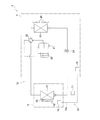
- FIG. 1 is a refrigerant circuit diagram showing a refrigerant circuit 10 of the air conditioner 1.
- the air conditioner 1 includes a refrigerant circuit 10, various sensors, and a control unit 70.
- the refrigerant circuit 10 includes a compressor 21, a four-way switching valve 22, an outdoor heat exchanger 23, an outdoor electromagnetic expansion valve 24, an accumulator 25, an outdoor fan 26, an indoor heat exchanger 41, an indoor fan 42, and the like.
- the compressor 21, the four-way switching valve 22, the outdoor heat exchanger 23, the outdoor electromagnetic expansion valve 24, the accumulator 25, and the outdoor fan 26 are accommodated in the outdoor unit 2, and the indoor heat exchanger 41 and The indoor fan 42 is accommodated in the indoor unit 4.
- the indoor fan 42 has its air volume adjusted in a plurality of stages by a control unit 70 which will be described later. In this case, the maximum air volume is 40 to 45 m 3 / s, and the minimum air volume is 15 to 20 m 3 / s.
- the detailed configuration of the indoor heat exchanger 41 will be described later.
- the four-way switching valve 22 can switch between a cooling operation cycle and a heating operation cycle.
- the connection state when performing the cooling operation is indicated by a solid line
- the connection state when performing the heating operation is indicated by a dotted line.
- the indoor heat exchanger 41 functions as a refrigerant cooler
- the outdoor heat exchanger 23 functions as a refrigerant heater
- the indoor heat exchanger 41 functions as a refrigerant heater.
- An indoor temperature sensor 43 is provided in the indoor unit 4.
- the indoor temperature sensor 43 is disposed on the indoor air inlet side, and detects the temperature (that is, the indoor temperature) before the indoor unit 4 takes in the room and passes through the indoor heat exchanger 41.
- the control unit 70 includes an outdoor control unit 72 that controls devices arranged in the outdoor unit 2, an indoor control unit 74 that controls devices arranged in the indoor unit 4, and accepts various setting inputs from the user, A controller 71 that performs display output and various sensors are connected by a communication line 70a.
- the control unit 70 performs various controls for the air conditioner 1.
- the control unit 70 receives selection of cooling operation, heating operation, and dehumidifying operation from the user via the controller 71.
- the control unit 70 causes the four-way switching valve 22 to be in a connected state similar to the cooling operation cycle, and drives the indoor fan 42 intermittently.
- the controller 70 is in a thermo-on state in which both the compressor 21 and the indoor fan 42 are continuously driven until a predetermined condition based on the set temperature input to the controller 71 is satisfied, and after the predetermined condition is satisfied. Control is performed so that the indoor fan 42 continues to be driven while the compressor 21 is stopped until the predetermined condition is not satisfied again.
- the indoor heat exchanger 41 is configured such that a plurality of fins 5 arranged in a plate thickness direction with a predetermined fin pitch are penetrated by a heat transfer tube through which a refrigerant flows. This is a so-called finned tube heat exchanger.
- the plate thickness per fin 5 is preferably 80 to 120 ⁇ m, for example.
- the fin pitch is preferably 1.0 to 2.5 mm, for example.
- the fin 5 of the indoor heat exchanger 41 has an aluminum base 8, a corrosion-resistant layer 7, and a hydrophilic layer 6.
- the aluminum substrate 8 is made of aluminum as a metal having good thermal conductivity in order to increase heat exchange efficiency.
- the aluminum substrate 8 may be made of pure aluminum or an aluminum alloy.
- the corrosion resistant layer 7 is provided between the aluminum base 8 and the hydrophilic layer 6 and has a resin corrosion resistant layer 7a and a chromate treatment layer 7b.
- the chromate treatment layer 7 b is a layer having corrosion resistance formed by subjecting the surface of the aluminum base 8 to chromate treatment.
- the resin corrosion resistant layer 7a is a layer having corrosion resistance composed of one or more selected from the group consisting of an epoxy resin, an acrylic resin, a urethane resin, and a phenol resin.
- the thermosetting epoxy resin is preferable from the viewpoint of easily improving the adhesion between the aluminum base 8 and the hydrophilic layer 6.
- the resin corrosion-resistant layer 7a may be appropriately omitted depending on the use environment and application.
- a chromate treatment layer (corrosion-resistant layer) 207 that protects the aluminum base 208, such as the fin 205 shown in FIG.
- a hydrophilic layer 206 may be provided on the surface.
- the hydrophilic layer 6 constitutes the surface layer of the fin 5 of the indoor heat exchanger 41. Details of the hydrophilic layer of the present invention will be described below.
- (4) Structure of hydrophilic layer The hydrophilic layer has a contact angle with water of 50 ° or less on the surface, and the water content in the hydrophilic layer per 1 dm 2 of the hydrophilic layer is 400 mg / dm 2 or less.
- the contact angle with respect to the water on the surface of the hydrophilic layer is not particularly limited as long as it is 50 degrees or less, but the resistance to air passing through the heat exchanger is suppressed to a smaller level, and the scattering of condensed water into the room is suppressed. From the viewpoint of making it, it is preferably 40 degrees or less, and more preferably 30 degrees or less.
- the contact angle is a value measured according to the method shown in “JIS R 3257 Wetability Test Method for Substrate Glass Surface”.
- the water content of the hydrophilic layer is the weight of water that can be held in the thickness portion corresponding to the surface 1 dm 2 of the hydrophilic layer (the portion between the surface and the corrosion-resistant layer), and is sufficiently dried.
- the initial weight of the fins immersed in water at 1 mm or more at the lower end of the fins at room temperature is taken as the initial weight, immersed in water at a predetermined depth and left for 14 hours, and then returned to the position where the initial weight was measured. This is a value obtained by dividing the difference from the initial weight measured after 30 seconds from the initial weight by the surface area (hereinafter, simply referred to as “water content”).
- the “water content” is measured in a room temperature environment at an ambient temperature of 28 ° C., and the sample used for the measurement is a sample dried for at least 16 hours with a dryer at 80 ° C.
- the surface area refers to the total area of both the front and back surfaces.
- the upper limit of the water content of the hydrophilic layer is not particularly limited as long as it is 400 mg / dm 2 or less, but is preferably 300 mg / dm 2 or less, and preferably 240 mg / dm 2 or less from the viewpoint of reducing the odor component retained. It is more preferable that it is 180 mg / dm 2 or less.
- the lower limit value of the water content of the hydrophilic layer is not particularly limited, but if the water content of the hydrophilic layer is too low, it tends to cause a decrease in the hydrophilic ability of the surface of the hydrophilic layer, so it should be 60 mg / dm 2 or more. Is preferred.
- the combination of the contact angle and water content of the hydrophilic layer is not particularly limited as long as it satisfies the above conditions, but the contact angle is 5 to 40 degrees and the water content is 60 to 240 mg / dm 2 . More preferably, the contact angle is 5 to 30 degrees and the water content is 90 to 210 mg / dm 2 .
- the film thickness of the hydrophilic layer is not particularly limited, but is preferably 0.1 ⁇ m or more in order to ensure sufficient hydrophilicity.
- the upper limit of the thickness of the hydrophilic layer is not particularly limited, but is 10 ⁇ m or less from the viewpoint of sufficiently exhibiting the heat exchange capability by securing the space between the fins and suppressing the ventilation resistance to a small value. It is preferable.
- the material of the hydrophilic layer is not particularly limited as long as it has the above water content and contact angle conditions, but is selected from the group consisting of (i) carboxylic acid group, sulfonic acid group, hydroxy group, amide group and ether bond.
- a polymer composed of a monomer having one or more hydrophilic functional groups, (ii) a copolymer composed of the monomer, or (iii) the polymer And a mixture of the above-mentioned copolymer can be contained as a film-forming component.
- These functional groups can be appropriately selected in order to adjust the degree of hydrophilicity imparted to the hydrophilic layer.
- the carboxylic acid groups and / or sulfonic acid groups may be alkali metal salts.
- the alkali metal salt include lithium salt, sodium salt, potassium salt and the like, and sodium salt is preferable.
- Specific examples of the resin containing the polymer or copolymer (i) to (iii) above include polyvinyl alcohol resins (polyvinyl alcohol and derivatives thereof), polyacrylamide resins (polyacrylamide and its derivatives). Derivatives), polyacrylic acid resins (polyacrylic acid and its derivatives), cellulose resins (for example, sodium carboxymethyl cellulose, carboxymethyl cellulose ammonium), polyethylene glycol resins (for example, polyethylene glycol, polyethylene oxide) and the like.
- As the resins (i) to (iii) for example, water-dispersible silica (colloidal silica), alkali silicate (water glass) and the like may be contained.
- the manufacturing method of indoor heat exchanger 41 mentioned above is not specifically limited.
- the prepared aluminum substrate is subjected to chromate treatment and dried, and then the resin constituting the resin corrosion-resistant layer is applied to the chromate-treated surface, dried, and the resin constituting the hydrophilic layer is further dried. Fins can be obtained by applying and drying. In the drying step here, drying may be performed by heating.
- the above-mentioned aluminum base material may be previously formed with a plurality of openings for penetrating the heat transfer tubes. Further, the plurality of openings may be provided after the hydrophilic layer is formed.
- a plurality of the fins thus obtained are arranged in the plate thickness direction, a heat transfer tube is inserted into the opening portion, and the heat transfer tube is expanded in that state, so that the plurality of fins and the heat transfer tube Are integrated to obtain a heat exchanger.
- the indoor heat exchanger 41 described above can be obtained by incorporating the heat exchanger obtained as described above as a use side heat exchanger of the refrigeration cycle. (6) Operation As described above, when the control unit 70 is in the thermo-on state in which both the compressor 21 and the indoor fan 42 are continuously driven while the cooling operation and the dehumidifying operation are performed, the indoor heat exchanger 41 The cooled refrigerant flows inside the heat transfer tube. As a result, the fin 5 is also cooled, moisture in the air flowing on the surface of the fin 5 is condensed, and the condensed water is attached to the surface of the fin 5.
- the condensed water does not form droplets and is in a state of being familiar with the surface, and is not scattered indoors along with the flow of conditioned air. Furthermore, due to the hydrophilic ability of the hydrophilic layer 6, the condensed water is present on the surface, so that the increase in ventilation resistance is suppressed without narrowing the space between the fins 6, and the heat exchange capacity is sufficient. It is possible to secure. In addition, since the hydrophilic layer 6 is adjusted to have a low water content, the amount of condensed water retained therein is kept small.
- the condensed water that can no longer be held on the surface of the fin 5 passes through the surface of the fin 5 and falls to a drain pan (not shown), and is drained along a drainage path.
- a drain pan not shown
- most of the condensed water in which the odor component is dissolved is treated as waste water.
- thermo-off state in which the indoor fan 42 is continuously driven is set.
- a part of the condensed water on the surface of the fin 5 of the indoor heat exchanger 41 is drained from the drain pan along the drainage path, and the other part is vaporized.
- the surface of the hydrophilic layer 6 of the fin 5 is in a dry state, the inside of the hydrophilic layer 6 of the fin 5 starts to dry, but the moisture retained inside the hydrophilic layer 6 is Less is suppressed. For this reason, since the amount of the odor component dissolved in the water held inside the hydrophilic layer 6 is also reduced, the amount of the odor component sent out from the indoor heat exchanger 41 to the room in the thermo-off state It is possible to sufficiently reduce.
- the odor sensor can be used even if the concentration is as low as the recognition threshold (minimum stimulation amount that can be recognized as to what kind of odor) the normal human can perceive in relation to the detection limit of the odor sensor used. It was also a condition that it could be detected.
- the recognition threshold minimum stimulation amount that can be recognized as to what kind of odor
- acetic acid was employed as an odor component that satisfies the above conditions.
- the vapor pressure of acetic acid at 20 ° C. is 1.5 kPa, which is lower than the vapor pressure of 2.3 kPa under the same conditions of water.
- the odor sensor used this time can be sufficiently detected even at a concentration of acetic acid recognition threshold (0.006 ppm).
- 7-3) Experimental method The heat exchangers of the examples and comparative examples are configured using fins as models, and the temperature is 25 ⁇ 0.5 ° C. and the relative humidity is 70 ⁇ 5%. The experiment was performed by flowing cooling water instead of the refrigerant in the portion corresponding to the heat transfer tube while being arranged. As the cooling water, 8 ° C.
- the heat exchanger model configured here has a fin diameter of 2 mm with a diameter of ⁇ 6 to 8 mm with respect to a fin group arranged with a fin pitch of 1.2 mm and a total thickness of 250 to 270 mm. It was constructed by passing through a heat transfer tube having a total effective length of 400 mm.
- the blower is arranged on the upstream side of the heat exchanger, and the arrangement relationship is such that the air flow passes between the fins.
- the wind speed supplied to the heat exchanger was 1.5 m / s.
- the odor sensor was measured for air passing through a heat exchanger and flowing through a position 0.1 m downstream of the heat exchanger.
- the brand name: portable odor sensor XP-329 III R made by Shin Cosmos Electric Co., Ltd. was used as the odor sensor.
- human sense of smell was used at the same position as the odor sensor.
- Each heat exchanger is immersed in a pool filled with a 5 wt% aqueous acetic acid solution for 2 hours before being used in the test, and then is removed to remove the remaining aqueous acetic acid solution on the fin surface of the heat exchanger. It was immersed twice in the filled pool. Thereby, the acetic acid aqueous solution remaining on the surface of the fin of the heat exchanger was substantially removed, and only the acetic acid retained inside the hydrophilic layer of the fin could be evaluated.
- the heat exchanger that has completed the acetic acid adhesion operation is configured to supply cooling water (8) to the heat transfer tube while supplying an air flow with a blower in order to reproduce the state of the thermo-on operation when used in an actual refrigeration cycle. This was continued until the condensed water produced on the fin surface was dripped. When condensed water dripped from the fins, the cooling water flowing through the heat transfer tube was stopped while continuing to supply the air flow by the blower in order to reproduce the state of the thermo-off operation when used in an actual refrigeration cycle. The odor sensor and sensory test were performed from the time when the cooling water flowing through the heat transfer tube was stopped. The measurement of the odor sensor was terminated when the detection value of the odor sensor became zero.
- This odor intensity is a six-level odor intensity display method (0: no odor, 1: the presence of odor is understood, 2: a weak smell that understands what smell is, 3: an odor that can be easily detected) 4: strong odor, 5: intense odor).
- the weight of acetic acid contained in 1 g of the heat exchanger fin sample was measured using GC-MS.
- the purpose is to reduce the odor components that humans sense, so it is desirable to measure the degree of odors actually sensed by humans, but in order to maintain the objectivity of evaluation, A sensor was used.
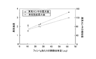
- the results obtained by simultaneously performing both sensory evaluation and odor sensor measurement on different types of samples are shown in the graph of FIG.
- the graph of FIG. 5 there is a proportional relationship between the integrated value of the sensory evaluation and the integrated value of the odor component measured using the odor sensor. It was confirmed that the odor perceived by humans was objectively indicated by the detected value of the odor sensor.
- the weight of moisture that can be held in the thickness portion (portion between the surface and the corrosion-resistant layer) corresponding to the surface 1 dm 2 of the hydrophilic layer of the fin of the heat exchanger, and acetic acid in the fin 1 g of the heat exchanger The result of investigating the correlation with the content of is shown in the graph of FIG.
- the moisture content of the fins is determined by immersing the fins in a predetermined depth of water, with the weight of the fins sufficiently dried at room temperature, with the lower end of the fins immersed in water for 1 mm or more.
- the “water content” was measured in a normal temperature environment with an atmospheric temperature of 28 ° C., and the sample used for the measurement was dried for 16 hours or more with a dryer at 80 ° C.
- the surface area was the sum of the areas of both the front and back surfaces.
- the weight of acetic acid contained in 1 g of the heat exchanger fin sample was measured using GC-MS. As shown in the graph of FIG. 6 above, it was confirmed that a proportional relationship was established between the water content of the fin and the content of acetic acid of the fin. Thereby, it can be said that when the water content of the fins is large, the weight of acetic acid contained in the fins also increases.
- Example 1 As Example 1, a sample in which the water content of the hydrophilic layer was 155 mg / dm 2 was prepared.
- Example 2 As Example 2, a sample in which the water content of the hydrophilic layer was 190 mg / dm 2 was prepared.
- Example 3 As Example 3, a sample in which the water content of the hydrophilic layer was 120 mg / dm 2 was prepared.
- Comparative Example 1 As Comparative Example 1, a sample (trade name: CC430, manufactured by Sumitomo Light Metal Co., Ltd.) in which the water content of the hydrophilic layer was 1300 mg / dm 2 was prepared.
- Comparative Example 2 As Comparative Example 2, a sample (trade name: CC431, manufactured by Sumitomo Light Metal Co., Ltd.) in which the water content of the hydrophilic layer was 850 mg / dm 2 was prepared.
- Comparative Example 3 As Comparative Example 3, a sample (Kobe Steel Co., Ltd., trade name: KS130B) having a water content of the hydrophilic layer of 480 mg / dm 2 was prepared.
- Comparative Example 4 As Comparative Example 4, a sample in which the water content of the hydrophilic layer was 120 mg / dm 2 was prepared.
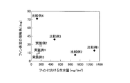
- FIG. 8 shows the water content and the integrated value of the odor sensor in each of Examples 1 to 3 and Comparative Examples 1 to 4.
- Comparative Examples 1 to 3 have a high water content, so the odor component becomes a problem.
- the water content can be reduced. Therefore, it turned out that the problem of an odor component can be eliminated.
- the above Examples 1 to 3 and Comparative Example The contact angle was measured for each of 1-4.
- the contact angle on the surface of the hydrophilic layer of the sample of Example 1 was 15 degrees.
- the contact angle on the surface of the hydrophilic layer of the sample of Example 2 was 27 degrees.
- the contact angle on the surface of the hydrophilic layer of the sample of Example 3 was 13 degrees.
- the contact angle on the surface of the hydrophilic layer of the sample of Comparative Example 1 was 20 degrees.
- the contact angle on the surface of the hydrophilic layer of the sample of Comparative Example 2 was 11.4 degrees.
- the contact angle on the surface of the hydrophilic layer of the sample of Comparative Example 3 was 40 degrees.
- the contact angle on the surface of the hydrophilic layer of the sample of Comparative Example 4 was 77 degrees.
- the contact angle with respect to the water on the surface of the hydrophilic layer capable of suppressing the ventilation resistance as a heat exchanger and suppressing the scattering of the condensed water is 50 degrees or less.
- the value of this contact angle was determined as a contact angle that satisfies the following condition where the ventilation resistance ratio between the ventilation resistance A and the ventilation resistance B (the ventilation resistance B / the ventilation resistance A) is 1.54 or less.
- This airflow resistance A is a condition where the surface of the hydrophilic layer of the fins is dry with a wind speed condition of 1.5 m / s on the front surface of the heat exchanger for a heat exchanger model with a fin pitch of 1.2 mm intervals.
- the ventilation resistance when it is placed in an environment with a dry bulb temperature of 21 ° C. and a wet bulb temperature of 15 ° C. and operated for 2 hours in a state where the temperature of the refrigerant passing through the heat transfer tube is 50 ° C.
- the ventilation resistance B is set in an environment with a dry bulb temperature of 27 ° C. and a wet bulb temperature of 19.5 ° C. with the wind speed condition at the front surface of the heat exchanger being 1.5 m / s and the hydrophilic layer surface of the fin being dry. It is the value of the ventilation resistance in the state where the refrigerant temperature passing through the inside of the heat transfer tube is operated for 8 hours with the temperature of the refrigerant being 5 ° C.
- the contact angle on the surface of the hydrophilic layer of the fin of the heat exchanger in the present invention is set to 50 degrees or less.
- FIG. 9 shows the relationship between the water content and the contact angle in each of Examples 1 to 3 and Comparative Examples 1 to 4.
- the contact angles are all 50 degrees or less, which satisfies the conditions.
- Comparative Example 4 although the water content was 400 mg / dm 2 or less, which was good, the contact angle was 50 degrees or more, and thus it was found that the condition was not satisfied.
- the fin, heat exchanger, and air conditioner of the heat exchanger of the present invention can suppress increase in ventilation resistance and water scattering even when condensed water adheres to the fin surface, and reduce odor generation. Therefore, it is particularly useful when used in an air-conditioning apparatus that performs at least a cooling operation or a dehumidifying operation.
- Air conditioner 1 Air conditioner 5 Fin (heat exchanger fin) 6 Hydrophilic layer 7 Corrosion resistant layer 8 Aluminum base material (base material) 41 Indoor heat exchanger (heat exchanger)
Landscapes
- Engineering & Computer Science (AREA)
- Mechanical Engineering (AREA)
- General Engineering & Computer Science (AREA)
- Physics & Mathematics (AREA)
- Thermal Sciences (AREA)
- Chemical & Material Sciences (AREA)
- Wood Science & Technology (AREA)
- Life Sciences & Earth Sciences (AREA)
- Combustion & Propulsion (AREA)
- Materials Engineering (AREA)
- Organic Chemistry (AREA)
- Geometry (AREA)
- Heat-Exchange Devices With Radiators And Conduit Assemblies (AREA)
- Air Conditioning Control Device (AREA)
- Laminated Bodies (AREA)
Abstract
Description
この特許文献1に記載の空気調和装置では、熱交換器のフィン表面に付着した凝縮水が、運転停止状態においてもフィン表面に長い間残存していると、環境浮遊物の付着や菌の増殖が生じ、臭いを発生していることを問題視している。そして、この問題を解決するために、凝縮水が熱交換器のフィン表面に残存する時間を短くさせる目的で、フィン表面に親水層を形成させるだけでなく、フィン形状として凝縮水が保持されにくい形状を採用している。
これに対して、冷房運転中や除湿運転中に、空気調和装置の圧縮機および室内ファンの両方が駆動しているサーモオン状態から、圧縮機が停止して室内ファンが駆動し続けているサーモオフ状態に切り換わった後(再びサーモオン状態に移行する前)に、臭気を感じることが多いことを、本願発明者らは見出した。
以上の知見に基づいて、空気調和装置から発生する臭気を従来よりも低減させる余地があると考え、上記特許文献1で検討されているような、熱交換器のフィン表面の凝縮水に対する運転停止状態での環境浮遊物の付着や菌の繁殖等という原因とは異なる、新たな臭気発生原因の存在を検討した。
さらに、発明者らは、鋭意検討を重ねた結果、このような臭気を感じさせる特定の臭気成分は、熱交換器のフィンの表面における凝縮水と共に存在している臭気成分よりも、むしろ、熱交換器のフィンの親水層に保持された水分と共に存在している臭気成分のほうが、上記サーモオフ状態に切り換わった後に感じる臭気としては問題であることに着目した。そこで、発明者らは、この特定の臭気成分の熱交換器における保持量を左右しているフィンの構成や特性について検討を行ったところ、熱交換器のフィンの親水層が保持している水分量(含水量)に起因して、フィンにおける特定の臭気成分の保持量が変化していることを見出した。
ところが、熱交換器のフィンの親水層の性質として、単に、含水量が低いものを採用した場合には、フィンの表面における親水能も同時に低減してしまうため、熱交換器のフィンの表面で凝縮水がはじかれてしまい、室内側に向かう凝縮水の飛散が生じ、フィン同士の間の通風抵抗が増大することで能力が低下してしまうことになる。
本発明は、上述した点に鑑みて、さらに検討を重ねることで完成されたものであり、本発明の課題は、熱交換器における通風抵抗の増大および凝縮水の飛散を抑制しつつ、臭気の発生を抑制可能な熱交換器のフィン、熱交換器、および、空気調和装置を提供することにある。
以上により、この熱交換器のフィンによると、熱交換器における通風抵抗の増大および凝縮水の飛散を抑制しつつ、臭気の発生を抑制させることが可能となっている。
この熱交換器のフィンでは、熱交換器のフィン同士の間における通風抵抗の低減および凝縮水の飛散をより確実に抑制させることができる。
この熱交換器のフィンでは、親水層の表面における親水能をより確実に確保することが可能になる。
この空気調和装置は、熱交換器のフィンの表面に凝縮水が残存している状態でサーモオフ運転制御が行われる場合であっても、発生する臭気成分の量を少なく抑えることができる。
本発明の第2観点に係る熱交換器のフィンでは、熱交換器のフィン同士の間における通風抵抗の低減および凝縮水の飛散をより確実に抑制させることができる。
本発明の第3観点に係る熱交換器のフィンでは、親水層の表面における親水能をより確実に確保することが可能になる。
本発明の第6観点に係る空気調和装置では、熱交換器のフィンの表面に凝縮水が残存している状態でサーモオフ運転制御が行われる場合であっても、発生する臭気成分の量を少なく抑えることができる。
図1に、空気調和装置1の冷媒回路10を示す冷媒回路図を示す。
(1)空気調和装置1の概略構成
空気調和装置1は、熱源側装置としての室外機2と、利用側装置としての室内機4とが冷媒配管によって接続されて、利用側装置が配置された空間の空気調和を行う。この空気調和装置1は、冷媒回路10、各種センサおよび制御部70を有している。
冷媒回路10は、圧縮機21、四路切換弁22、室外熱交換器23、室外電磁膨張弁24、アキュームレータ25、室外ファン26、室内熱交換器41、および、室内ファン42等を備えており、これらが接続されること構成されている。なお、圧縮機21、四路切換弁22、室外熱交換器23、室外電磁膨張弁24、アキュームレータ25、および、室外ファン26は、室外機2内に収容されており、室内熱交換器41および室内ファン42は、室内機4内に収容されている。この室内ファン42は、後述する制御部70によってその風量が複数段階に調節されるが、その場合の最大風量は40~45m3/sであり、最低風量は15~20m3/sである。なお、室内熱交換器41の詳細構成については、後述する。
なお、室内機4内には、室内温度センサ43が設けられている。この室内温度センサ43は、室内空気の吸入口側に配置され、室内機4が室内から取り込んで、室内熱交換器41を通過する前の温度(すなわち、室内温度)を検出する。
制御部70は、室外機2内に配置される機器を制御する室外制御部72、室内機4内に配置されている機器を制御する室内制御部74、ユーザからの各種設定入力を受け付けたり各種表示出力を行ったりするコントローラ71、および、各種センサが、通信線70aによって接続されることで構成されている。この制御部70は、空気調和装置1を対象とした種々の制御を行う。
(2)室内熱交換器41の構成
室内熱交換器41は、板厚方向に所定のフィンピッチで複数枚配置されたフィン5群が、内部を冷媒が流れる伝熱管によって貫通されて構成された、いわゆるフィンチューブ式熱交換器である。ここで、フィン5の一枚当たりの板厚は、例えば、80~120μmであることが好ましい。また、フィンピッチは、例えば、1.0~2.5mmであることが好ましい。
室内熱交換器41のフィン5は、図2に示すように、アルミ基材8、耐食層7、および親水層6を有している。
アルミ基材8は、熱交換効率を上げるために熱伝導性の良好な金属としてアルミニウムから構成されている。このアルミ基材8は、純粋なアルミニウムから構成されていてもよいし、アルミニウム合金から構成されていてもよい。
耐食層7は、アルミ基材8と親水層6との間に設けられ、樹脂耐食層7aと、クロメート処理層7bとを有している。このうち、クロメート処理層7bは、アルミ基材8の表面に対してクロメート処理を施すことによって形成された耐食性を有する層である。樹脂耐食層7aは、エポキシ樹脂、アクリル樹脂、ウレタン樹脂、および、フェノール樹脂からなる群より選ばれる一種または二種以上によって構成された、耐食性を有する層である。なお、アルミ基材8および親水層6との密着性を良好にさせやすい観点から、熱硬化性であるエポキシ樹脂が好ましい。
親水層6は、室内熱交換器41のフィン5の表層を構成している。以下に、本発明の親水層の詳細を述べる。
(4)親水層の構成
親水層は、表面における水に対する接触角が50度以下であり、かつ、親水層の表面1dm2当たりの親水層内部の含水量が400mg/dm2以下である。
親水層の表面における水に対する接触角としては、50度以下であれば特に限定されないが、熱交換器を通過する空気に対する通風抵抗をより小さく抑えること、および、室内への凝縮水の飛散を抑制させる観点から、40度以下であることが好ましく、30度以下であることがより好ましい。なお、ここでの接触角は、「JIS R 3257 基板ガラス表面のぬれ性試験方法」に示された方法に従って測定される値である。
親水層の膜厚は、特に限定されないが、親水性を十分に確保するためには、0.1μm以上であることが好ましい。なお、親水層の膜厚の上限については、特に限定されないが、フィン同士の間の空間を確保して通風抵抗を小さく抑えることで熱交換能力を十分に発揮させる観点からは、10μm以下であることが好ましい。
親水層の材質は、上記含水量と接触角の条件を備えるものであれば特に限定されないが、(i)カルボン酸基、スルホン酸基、ヒドロキシ基、アミド基およびエーテル結合よりなる群から選択される1種または2種以上の親水性の官能基を有する単量体から構成される重合体、(ii)前記単量体を含んで構成される共重合体、または、(iii)前記重合体と前記共重合体との混合物、のいずれかを塗膜形成成分として含有することができる。なお、これらの官能基は、親水層に付与する親水性の程度を調節するために適宜選択されうる。このうち、カルボン酸基および/またはスルホン酸基については、一部または全部がアルカリ金属塩であってよい。このアルカリ金属塩としては、リチウム塩、ナトリウム塩、カリウム塩等が挙げられ、なかでもナトリウム塩が好ましい。また、上記(i)~(iii)の重合体もしくは共重合体を含有する樹脂としては、具体的には、ポリビニルアルコール系樹脂(ポリビニルアルコールとその誘導体)、ポリアクリルアミド系樹脂(ポリアクリルアミドとその誘導体)、ポリアクリル酸系樹脂(ポリアクリル酸とその誘導体)、セルロース系樹脂(例えば、カルボキシメチルセルロースナトリウム、カルボキシメチルセルロース系アンモニウム)、ポリエチレングリコール系樹脂(例えば、ポリエチレングリコール、ポリエチレンオキサイド)等が挙げられる。この(i)~(iii)の樹脂としては、例えば、水分散性シリカ(コロイダルシリカ)、アルカリケイ酸塩(水ガラス)等を含んでいても良い。
上述した室内熱交換器41の製造方法は、特に限定されない。
例えば、用意したアルミ基材に対してクロメート処理を施して乾燥させ、その後、クロメート処理がされた表面に樹脂耐食層を構成する樹脂を塗布して、乾燥させ、さらに親水層を構成する樹脂を塗布して乾燥させることでフィンを得ることができる。ここでの乾燥工程では、加熱によって乾燥させてもよい。
なお、上述のアルミ基材は、予め、伝熱管を貫通させるための開口が複数形成されていてもよい。また、複数の開口は、親水層が形成された後に設けるようにしてもよい。
このようにして得られたフィンは、板厚方向に複数枚並べられ、上記開口部分に対して伝熱管が挿入され、その状態で伝熱管が拡管処理されることで、複数のフィンと伝熱管とが一体化され、熱交換器が得られる。
(6)動作
上述したように、冷房運転や除湿運転が行われている状態で、制御部70が、圧縮機21および室内ファン42の両方を駆動させ続けるサーモオン状態とすると、室内熱交換器41の伝熱管内部には冷やされた冷媒が流れることになる。これにより、フィン5も冷却され、フィン5の表面を流れる空気中の水分が凝縮し、凝縮水となってフィン5表面に付着した状態となる。フィン5表面は、上記親水層6の親水能を有しているため、凝縮水は液滴になることなく、表面になじんだ状態となり、調和空気の流れとともに室内側に飛散することがない。さらに、上記親水層6の親水能によって、凝縮水が表面上で広がって存在しているため、フィン6同士の間の空間を狭めることなく、通風抵抗の増大を抑え、熱交換能力を十分に確保することが可能になっている。また、上記親水層6は、含水量が低く調整されているため、内部において保持する凝縮水の量が少なく抑えられている。なお、サーモオン状態において、フィン5の表面に保持しきれなくなった凝縮水は、フィン5の表面をつたって、図示しないドレンパンまで落下し、排水経路をたどって排水処理される。ここで、臭気成分が溶け込んだ凝縮水の多くが廃水処理されることになる。
以下、上記実施形態に採用可能な熱交換器のフィンの例について、具体的に検討した結果を述べる。
(7-1)サンプルについて
後述するように実施例1~3、比較例1~4に対応する各サンプルのフィンを用意し、各サンプルから生じうる臭気の度合いを比較した。なお、用意したサンプルは、親水層の表面を親水化させるためのプラズマ処理や酸化剤処理の程度を調節しつつ、親水層内部を疎水化させるための加熱の程度や架橋剤の配合量や種類を調節することで、性質の異なるサンプルを用意した。
(7-2)評価対象とする臭気成分について
問題としている臭気成分は、親水層の内部に凝縮水とともに保持される可能性があるものであるため、水溶性であることを条件とした。また、フィンの親水層表面の凝縮水が揮発した後に生じる臭気成分を問題視していることから、空気調和装置の熱交換器の使用温度状況下において、水よりも揮発しにくい性質を有するものであることを条件とした。そこで、従来より、当該技術分野において臭気成分の代表例であって、空気質に含まれる対象として報告されている脂肪酸を対象とすることとした。また、試験では、官能評価を伴うため、人体への影響度合いが比較的小さい対象であることも条件とした。さらに、使用する臭気センサの検出限度との関係で、通常の人間が関知可能な認識閾値(何の臭気であるのか認識可能な最小の刺激量)程度の低濃度であっても、臭気センサが検知可能であることも条件とした。
なお、酢酸の20℃での蒸気圧は、水の同条件下での蒸気圧2.3kPaよりも低い、1.5kPaである。また、今回用いた臭気センサでは、酢酸の認識閾値(0.006ppm)の濃度であっても、十分に検知可能なものである。
(7―3)実験方法について
モデルとするフィンを用いて各実施例および比較例の熱交換器を構成し、25±0.5℃の温度でかつ70±5%の相対湿度の条件下に配置しつつ、伝熱管に相当する部分には冷媒の代わりに冷却水を流すことで実験を行った。冷却水としては、8℃の冷水を用いた。なお、ここで構成した熱交換器のモデルは、フィンピッチが1.2mm間隔で、板厚方向に合計250~270mmとなるように並べたフィン群に対して、菅径がφ6~8mmで2列の合計有効長が400mmの伝熱管を貫通させることによって構成した。
臭気センサは、熱交換器を通過して、熱交換器の下流側0.1mの位置を流れる空気を対象として測定した。ここでは、臭気センサは、新コスモス電機株式会社製の商品名:ポータブル型ニオイセンサ XP-329 III Rを用いた。
また、官能試験では、臭気センサと同様の位置における人間の嗅覚による感知を採用した。
各熱交換器は、試験に用いる前に、5wt%濃度の酢酸水溶液で満たされたプールに2時間浸漬させた後、熱交換器のフィン表面に残存する酢酸水溶液を除去するために、純粋で満たされたプールに2回浸漬させた。これにより、熱交換器のフィンの表面に残る酢酸水溶液が実質的に除去され、フィンの親水層内部に保持されている酢酸のみを評価することができる状況とした。
フィンから凝縮水が滴下すると、実際の冷凍サイクルで用いられた場合のサーモオフ運転の状況を再現させるために、送風機による空気流れの供給を続けながら、伝熱管に流す冷却水を止めた。臭気センサおよび官能試験は、この伝熱管に流す冷却水が止められた時点以降から行った。臭気センサの測定終了は、臭気センサの検知値が0になった時点とした。また、官能試験も同様に、人間が臭気を感じられなくなるまでとした。
(7-4)各値の相関関係の確認
なお、実施例および比較例の試験を行う前に、親水層に保持される酢酸の量と実際に測定される臭気との間に相関関係が有ることを確認するために、酢酸含有量が異なるサンプルを複数用意した。具体的には、熱交換器を浸漬させるプール内の酢酸の濃度をサンプル毎に変化させることで、親水層に保持される臭気成分量(残存酢酸量)の異なるサンプルを用意した。その後、これらのサンプルを用いて上記実験を行い、臭気センサで検知される臭気成分の積分値(臭気を検知し始めてから臭気を検知しなくなるまでの合計量)、および、臭気強度を評価した。この臭気強度とは、一般的なにおいの評価手法である6段階臭気強度表示法(0:無臭、1:においの存在が分かる、2:何のにおいか分かる弱いにおい、3:楽に感知できるにおい、4:強いにおい、5:強烈なにおい)に従って数値化されたものである。ここで、熱交換器のフィンのサンプル1gが含有している酢酸重量は、GC-MSを用いて測定した。以上のようにして把握された各サンプルのフィン1g当たりの酢酸含有量に対する臭気強度および臭気センサの検知値(上記臭気センサの測定値として画面表示される臭気指数)の関係を、図4に示す。この図4のグラフによると、フィン1g当たりの酢酸含有量に対する臭気強度の関係、および、フィン1g当たりの酢酸含有量に対する臭気センサの検知値の関係が、ともに比例関係にあることが確認された。以上により、フィンの親水層が保持している酢酸量と、人間が感知する臭気強度との相関関係の存在が示された。
さらに、熱交換器のフィンの親水層の表面1dm2に対応する厚み部分(表面と耐食層との間の部分)に保持させることが可能な水分の重量と、熱交換器のフィン1gにおける酢酸の含有量と、の相関関係を調べた結果を、図6のグラフに示す。ここで、フィンの含水量は、十分に乾燥しているフィンについて、常温下で、フィンの下端を1mm以上水に浸した状態での重量を初期重量とし、所定の深さ水に浸漬させて14時間放置した後、初期重量を測定した位置に戻した時から30秒後に測定する重量の初期重量との差を表面積で除して得られる値とした。なお、「含水量」の測定は、雰囲気温度28℃の常温環境下で行い、測定に用いるサンプルは80℃の乾燥機で16時間以上乾燥させたものを用いた。また、表面積は、表と裏の両面の面積の合計とした。また、熱交換器のフィンのサンプル1gが含有している酢酸重量は、GC-MSを用いて測定した。以上の図6のグラフに示されているように、フィンの含水量とフィンの酢酸の含有量との間には、比例関係が成立していることが確認された。これにより、フィンの含水量が多いと、フィンの含有する酢酸重量も増大することになる、といえる。
以上の関係を踏まえて、人間が感じる臭気を効果的に低減できたといえる場合の臭気成分の濃度条件に対応する臭気センサの積分値を特定したところ、臭気センサの積分値が4000以下であることが必要になることが分かった。そして、図7のフィンの含水量と臭気センサの積分値との関係を示したグラフによると、この臭気成分の条件を満足する熱交換器のフィンの親水層における含水量の条件は、400mg/dm2以下であることが分かった。
(実施例1)
実施例1として、親水層の含水量が155mg/dm2であるサンプルを用意した。
(実施例2)
実施例2として、親水層の含水量が190mg/dm2であるサンプルを用意した。
(実施例3)
実施例3として、親水層の含水量が120mg/dm2であるサンプルを用意した。
(比較例1)
比較例1として、親水層の含水量が1300mg/dm2であるサンプル(住友軽金属社製、商品名:CC430)を用意した。
比較例2として、親水層の含水量が850mg/dm2であるサンプル(住友軽金属社製、商品名:CC431)を用意した。
(比較例3)
比較例3として、親水層の含水量が480mg/dm2であるサンプル(神戸製鋼社製、商品名:KS130B)を用意した。
(比較例4)
比較例4として、親水層の含水量が120mg/dm2であるサンプルを用意した。
図8に、各実施例1~3および比較例1~4における含水量および臭気センサの積分値を示す。以上の図8に示された結果によると、比較例1~3では、含水量が多いため臭気成分が問題となり、実施例1~3および比較例4では含水量を少なく抑えることができているため、臭気成分の問題を解消できることが分かった。
実施例1のサンプルの親水層の表面における接触角は、15度であった。
実施例2のサンプルの親水層の表面における接触角は、27度であった。
実施例3のサンプルの親水層の表面における接触角は、13度であった。
比較例1のサンプルの親水層の表面における接触角は、20度であった。
比較例2のサンプルの親水層の表面における接触角は、11.4度であった。
比較例3のサンプルの親水層の表面における接触角は、40度であった。
比較例4のサンプルの親水層の表面における接触角は、77度であった。
5 フィン(熱交換器のフィン)
6 親水層
7 耐食層
8 アルミ基材(基材)
41 室内熱交換器(熱交換器)
Claims (6)
- 空気調和装置(1)の熱交換器(41)のフィン(5)であって、
基材(8)と、
親水層(6)と、
前記基材と前記親水層との間に設けられる耐食層(7)と、
を備え、
前記親水層の表面における水に対する接触角は、50度以下であり、
前記親水層の表面1dm2当たりの親水層内部の含水量は、400mg/dm2以下である、
熱交換器のフィン(5)。 - 前記親水層の表面における水に対する接触角は、30度以下であり、
請求項1に記載の熱交換器のフィン。 - 前記親水層の膜厚は、0.1μm以上である、
請求項1または2に記載の熱交換器のフィン。 - 前記親水層は、
カルボン酸基、スルホン酸基、ヒドロキシ基、アミド基およびエーテル結合よりなる群から選択される1種または2種以上の親水性の官能基を有する単量体から構成される重合体、
前記単量体を含んで構成される共重合体、または、
前記重合体と前記共重合体との混合物、
のいずれかを塗膜形成成分として含有する、
請求項1から3のいずれか1項に記載の熱交換器のフィン。 - 請求項1から4のいずれか1項に記載の熱交換器のフィンを備えた、
熱交換器(41)。 - 請求項5に記載の熱交換器と、
前記熱交換器に対して空気流れを送るファンと、
圧縮機と、
前記圧縮機の駆動を停止させた状態で前記ファンを駆動させるサーモオフ運転制御を行う制御部と、
を備えた空気調和装置(1)。
Priority Applications (7)
| Application Number | Priority Date | Filing Date | Title |
|---|---|---|---|
| AU2012263934A AU2012263934B2 (en) | 2011-05-31 | 2012-04-12 | Fin of Heat Exchanger, Heat Exchanger, and Air Conditioning Apparatus |
| BR112013030750-1A BR112013030750B1 (pt) | 2011-05-31 | 2012-04-12 | aleta de trocador de calor, trocador de calor e aparelho de condicionamento de ar |
| US14/122,558 US8944153B2 (en) | 2011-05-31 | 2012-04-12 | Fin of heat exchanger, heat exchanger, and air conditioning apparatus |
| CN201280026060.XA CN103562667B (zh) | 2011-05-31 | 2012-04-12 | 热交换器的翅片、热交换器和空气调节装置 |
| EP12793640.9A EP2706319B1 (en) | 2011-05-31 | 2012-04-12 | Heat exchanger fin, heat exchanger and air-conditioning device |
| KR1020137034575A KR101373959B1 (ko) | 2011-05-31 | 2012-04-12 | 열 교환기의 핀, 열 교환기 및 공기 조화 장치 |
| ES12793640.9T ES2585562T3 (es) | 2011-05-31 | 2012-04-12 | Aleta de intercambiador de calor, intercambiador de calor y dispositivo de aire acondicionado |
Applications Claiming Priority (4)
| Application Number | Priority Date | Filing Date | Title |
|---|---|---|---|
| JP2011122913 | 2011-05-31 | ||
| JP2011-122913 | 2011-05-31 | ||
| JP2011220694 | 2011-10-05 | ||
| JP2011-220694 | 2011-10-05 |
Publications (1)
| Publication Number | Publication Date |
|---|---|
| WO2012165058A1 true WO2012165058A1 (ja) | 2012-12-06 |
Family
ID=47258922
Family Applications (1)
| Application Number | Title | Priority Date | Filing Date |
|---|---|---|---|
| PCT/JP2012/059956 Ceased WO2012165058A1 (ja) | 2011-05-31 | 2012-04-12 | 熱交換器のフィン、熱交換器および空気調和装置 |
Country Status (9)
| Country | Link |
|---|---|
| US (1) | US8944153B2 (ja) |
| EP (1) | EP2706319B1 (ja) |
| JP (1) | JP5392371B2 (ja) |
| KR (1) | KR101373959B1 (ja) |
| CN (1) | CN103562667B (ja) |
| AU (1) | AU2012263934B2 (ja) |
| BR (1) | BR112013030750B1 (ja) |
| ES (1) | ES2585562T3 (ja) |
| WO (1) | WO2012165058A1 (ja) |
Families Citing this family (9)
| Publication number | Priority date | Publication date | Assignee | Title |
|---|---|---|---|---|
| CN104593781B (zh) * | 2015-02-04 | 2017-09-26 | 广东美的暖通设备有限公司 | 用于空调室外机的金属罐及其防腐处理工艺 |
| JP6596313B2 (ja) * | 2015-11-20 | 2019-10-23 | 株式会社Uacj | プレコートフィン及び熱交換器 |
| JP2017150736A (ja) * | 2016-02-24 | 2017-08-31 | 株式会社Uacj | フィン材及び熱交換器 |
| JP6732644B2 (ja) * | 2016-12-02 | 2020-07-29 | 日本ペイント・サーフケミカルズ株式会社 | 熱交換器、及び熱交換器の親水化処理方法 |
| JP2019020006A (ja) * | 2017-07-13 | 2019-02-07 | パナソニックIpマネジメント株式会社 | 熱交換器及びそれを用いた空気調和機 |
| US20230228503A1 (en) * | 2020-07-28 | 2023-07-20 | Mitsubishi Electric Corporation | Heat exchanger coating composition |
| CN115708403A (zh) * | 2021-08-20 | 2023-02-21 | 华为技术有限公司 | 均热板及其制备方法、电子设备 |
| CN114485253B (zh) * | 2022-01-25 | 2024-01-26 | 郑州轻工业大学 | 一种亲疏水转换的智能表面换热管 |
| CN116592478B (zh) * | 2023-05-31 | 2025-11-18 | 青岛海尔空调器有限总公司 | 用于消除空调器室内机异味的控制方法、装置及空调器 |
Citations (6)
| Publication number | Priority date | Publication date | Assignee | Title |
|---|---|---|---|---|
| JP2002162186A (ja) * | 2000-11-20 | 2002-06-07 | Mitsubishi Alum Co Ltd | ノンクロメート反応型下地層を有する熱交換器用フィン材およびそれを備えた熱交換器 |
| JP2003287394A (ja) * | 2002-03-27 | 2003-10-10 | Kobe Steel Ltd | 熱交換器用アルミニウム製フィン材およびこれを用いたフィン |
| JP2007225174A (ja) * | 2006-02-22 | 2007-09-06 | Fujifilm Corp | 熱交換器 |
| JP2008145063A (ja) * | 2006-12-11 | 2008-06-26 | Daikin Ind Ltd | 熱交換器および熱交換器を備えた空気調和装置 |
| JP2008215757A (ja) | 2007-03-07 | 2008-09-18 | Daikin Ind Ltd | 熱交換器 |
| JP2010159379A (ja) * | 2009-01-09 | 2010-07-22 | Mitsubishi Alum Co Ltd | 塗料組成物、その製造方法及び熱交換器用フィン |
Family Cites Families (6)
| Publication number | Priority date | Publication date | Assignee | Title |
|---|---|---|---|---|
| JPS60102978A (ja) * | 1983-11-11 | 1985-06-07 | Nippon Light Metal Co Ltd | 親水性皮膜を有する素形部材 |
| JP2683812B2 (ja) * | 1988-10-05 | 1997-12-03 | 昭和アルミニウム株式会社 | アルミニウムフィン付き熱交換器 |
| JP3233169B2 (ja) * | 1992-05-03 | 2001-11-26 | 株式会社西部技研 | 全熱交換器用素子およびその製造法 |
| CN1190633C (zh) * | 2001-09-24 | 2005-02-23 | 广东科龙电器股份有限公司 | 具有超亲水性能翅片的制作方法及空调换热器 |
| KR100727181B1 (ko) * | 2004-07-13 | 2007-06-13 | 현대자동차주식회사 | 자동차 에어컨디셔너 증발기용 친수 항균재 조성물 |
| JP4975970B2 (ja) * | 2005-01-21 | 2012-07-11 | 日本エクスラン工業株式会社 | 収着式熱交換モジュールおよびその製法 |
-
2012
- 2012-04-05 JP JP2012086527A patent/JP5392371B2/ja active Active
- 2012-04-12 KR KR1020137034575A patent/KR101373959B1/ko active Active
- 2012-04-12 US US14/122,558 patent/US8944153B2/en active Active
- 2012-04-12 EP EP12793640.9A patent/EP2706319B1/en active Active
- 2012-04-12 WO PCT/JP2012/059956 patent/WO2012165058A1/ja not_active Ceased
- 2012-04-12 BR BR112013030750-1A patent/BR112013030750B1/pt active IP Right Grant
- 2012-04-12 AU AU2012263934A patent/AU2012263934B2/en active Active
- 2012-04-12 CN CN201280026060.XA patent/CN103562667B/zh active Active
- 2012-04-12 ES ES12793640.9T patent/ES2585562T3/es active Active
Patent Citations (6)
| Publication number | Priority date | Publication date | Assignee | Title |
|---|---|---|---|---|
| JP2002162186A (ja) * | 2000-11-20 | 2002-06-07 | Mitsubishi Alum Co Ltd | ノンクロメート反応型下地層を有する熱交換器用フィン材およびそれを備えた熱交換器 |
| JP2003287394A (ja) * | 2002-03-27 | 2003-10-10 | Kobe Steel Ltd | 熱交換器用アルミニウム製フィン材およびこれを用いたフィン |
| JP2007225174A (ja) * | 2006-02-22 | 2007-09-06 | Fujifilm Corp | 熱交換器 |
| JP2008145063A (ja) * | 2006-12-11 | 2008-06-26 | Daikin Ind Ltd | 熱交換器および熱交換器を備えた空気調和装置 |
| JP2008215757A (ja) | 2007-03-07 | 2008-09-18 | Daikin Ind Ltd | 熱交換器 |
| JP2010159379A (ja) * | 2009-01-09 | 2010-07-22 | Mitsubishi Alum Co Ltd | 塗料組成物、その製造方法及び熱交換器用フィン |
Non-Patent Citations (1)
| Title |
|---|
| See also references of EP2706319A4 |
Also Published As
| Publication number | Publication date |
|---|---|
| EP2706319A4 (en) | 2014-06-04 |
| AU2012263934A1 (en) | 2014-01-09 |
| US8944153B2 (en) | 2015-02-03 |
| JP2013092351A (ja) | 2013-05-16 |
| US20140083657A1 (en) | 2014-03-27 |
| EP2706319B1 (en) | 2016-05-18 |
| CN103562667A (zh) | 2014-02-05 |
| JP5392371B2 (ja) | 2014-01-22 |
| ES2585562T3 (es) | 2016-10-06 |
| BR112013030750A2 (pt) | 2016-12-06 |
| BR112013030750B1 (pt) | 2020-06-30 |
| EP2706319A1 (en) | 2014-03-12 |
| KR20140007971A (ko) | 2014-01-20 |
| KR101373959B1 (ko) | 2014-03-12 |
| AU2012263934B2 (en) | 2015-05-21 |
| CN103562667B (zh) | 2015-11-25 |
Similar Documents
| Publication | Publication Date | Title |
|---|---|---|
| JP5392371B2 (ja) | 熱交換器のフィン、熱交換器および空気調和装置 | |
| CN101765753B (zh) | 热交换器以及其制造方法 | |
| CN205784707U (zh) | 热交换器以及制冷循环装置 | |
| JP2009180402A (ja) | 加湿器、熱交換器、加湿方法 | |
| JP2010036093A (ja) | 調湿装置 | |
| CN106196528A (zh) | 空调器及其控制方法 | |
| CN106403107A (zh) | 空调器及其控制方法 | |
| JP6603125B2 (ja) | 空気調和装置 | |
| JP3059307B2 (ja) | 撥水性及び着霜防止性が優れた部材及びその製造方法 | |
| Min et al. | Hydrophilic treatment and performance evaluation of copper finned tube evaporators | |
| JP2008256255A (ja) | 空気調和装置 | |
| JP7373227B2 (ja) | 熱交換器用部材、熱交換器、空気調和機用室内機、空気調和機用室外機、及び冷蔵庫 | |
| JP6052494B2 (ja) | 空気調和装置 | |
| CN109469996B (zh) | 利用冷凝水的膜蒸发冷凝器 | |
| CN120593551B (zh) | 翅片及其制备方法、换热器 | |
| JP7067054B2 (ja) | 伝熱部材及びこれを用いた熱交換器 | |
| JP6215990B2 (ja) | アルミニウム製フィン材 | |
| JP2008202931A5 (ja) | ||
| CN107741076A (zh) | 一种电梯用散热装置 | |
| Min et al. | Performance comparison of aluminum and copper finned tube evaporators used in a residential air-conditioner | |
| JP2008202931A (ja) | 熱交換器および熱交換器を備えた空気調和装置 | |
| KR20110088769A (ko) | 항균성과 친수성을 가지는 은나노 핀을 이용한 열교환기 | |
| JP2008145063A (ja) | 熱交換器および熱交換器を備えた空気調和装置 | |
| JP2000179899A (ja) | 空調装置 | |
| CN106871291A (zh) | 空调系统及空调控制方法 |
Legal Events
| Date | Code | Title | Description |
|---|---|---|---|
| 121 | Ep: the epo has been informed by wipo that ep was designated in this application |
Ref document number: 12793640 Country of ref document: EP Kind code of ref document: A1 |
|
| WWE | Wipo information: entry into national phase |
Ref document number: 14122558 Country of ref document: US |
|
| NENP | Non-entry into the national phase |
Ref country code: DE |
|
| WWE | Wipo information: entry into national phase |
Ref document number: 2012793640 Country of ref document: EP |
|
| ENP | Entry into the national phase |
Ref document number: 20137034575 Country of ref document: KR Kind code of ref document: A |
|
| ENP | Entry into the national phase |
Ref document number: 2012263934 Country of ref document: AU Date of ref document: 20120412 Kind code of ref document: A |
|
| REG | Reference to national code |
Ref country code: BR Ref legal event code: B01A Ref document number: 112013030750 Country of ref document: BR |
|
| ENP | Entry into the national phase |
Ref document number: 112013030750 Country of ref document: BR Kind code of ref document: A2 Effective date: 20131129 |