WO2012165200A1 - 通信制御装置及び通信制御方法 - Google Patents
通信制御装置及び通信制御方法 Download PDFInfo
- Publication number
- WO2012165200A1 WO2012165200A1 PCT/JP2012/062960 JP2012062960W WO2012165200A1 WO 2012165200 A1 WO2012165200 A1 WO 2012165200A1 JP 2012062960 W JP2012062960 W JP 2012062960W WO 2012165200 A1 WO2012165200 A1 WO 2012165200A1
- Authority
- WO
- WIPO (PCT)
- Prior art keywords
- cell
- parameter
- communication control
- base station
- control device
- Prior art date
- Legal status (The legal status is an assumption and is not a legal conclusion. Google has not performed a legal analysis and makes no representation as to the accuracy of the status listed.)
- Ceased
Links
Images







Classifications
-
- H—ELECTRICITY
- H04—ELECTRIC COMMUNICATION TECHNIQUE
- H04W—WIRELESS COMMUNICATION NETWORKS
- H04W36/00—Hand-off or reselection arrangements
- H04W36/16—Performing reselection for specific purposes
- H04W36/20—Performing reselection for specific purposes for optimising the interference level
-
- H—ELECTRICITY
- H04—ELECTRIC COMMUNICATION TECHNIQUE
- H04W—WIRELESS COMMUNICATION NETWORKS
- H04W28/00—Network traffic management; Network resource management
- H04W28/16—Central resource management; Negotiation of resources or communication parameters, e.g. negotiating bandwidth or QoS [Quality of Service]
-
- H—ELECTRICITY
- H04—ELECTRIC COMMUNICATION TECHNIQUE
- H04W—WIRELESS COMMUNICATION NETWORKS
- H04W72/00—Local resource management
- H04W72/50—Allocation or scheduling criteria for wireless resources
- H04W72/52—Allocation or scheduling criteria for wireless resources based on load
Definitions
- the present invention relates to a communication control apparatus and a communication control method for controlling a base station, and more specifically, to a communication control apparatus and a communication control method for controlling parameters relating to inter-cell interference coordination.
- LTE-A Long Term Evolution-Advanced
- 3GPP 3rd Generation Partnership Project
- RRH Remote Radio Head
- HetNet HetNet
- inter-cell interference coordination eICIC
- eICIC inter-cell interference coordination
- a radio resource block in the time domain in which the macro cell transmits a radio signal is determined by an Almost-Blank-subframe (ABS) pattern that controls the time domain allocated to the macro cell.
- ABS Almost-Blank-subframe
- the above-described inter-cell interference coordination has the following problems.
- the optimal ABS pattern according to the number of mobile stations connected to the macro cell and pico cell changes from time to time depending on the value of Cell Range Expansion (dB).
- dB Cell Range Expansion
- the present invention has been made in view of such a situation, and an object thereof is to provide a communication control device and a communication control method that can autonomously optimize parameters that change due to inter-cell interference coordination in a heterogeneous network. To do.
- a first feature of the present invention is that a first base station (base station 100) that forms a first cell (macro cell C11) having a predetermined cell radius, and a second cell radius that is smaller than the predetermined cell radius.
- a communication control device (communication control device 50) for controlling a second base station (eg, base station 200A) forming a cell (eg, pico cell C21), the number of mobile stations connected to the first cell;
- an acquisition unit (parameter acquisition unit 51) that acquires a first parameter determined based on the number of mobile stations connected to the second cell, and the first parameter acquired based on the first parameter acquired by the acquisition unit.
- a determination unit for determining a second parameter for changing the number of mobile stations connectable to a cell or the number of mobile stations connectable to the second cell; and the second unit determined by the determination unit 2 parameters
- the gist of the present invention is to include a notification unit (parameter notification unit 55) that notifies at least one of the first base station and the second base station.
- a second feature of the present invention is that a first base station that forms a first cell having a predetermined cell radius, and a second base station that forms a second cell having a cell radius smaller than the predetermined cell radius, A first parameter determined based on the number of mobile stations connected to the first cell or the number of mobile stations connected to the second cell; and Determining a second parameter for changing a number of mobile stations connectable to the first cell or a number of mobile stations connectable to the second cell based on the first parameter; And reporting two parameters to at least one of the first base station and the second base station.
- FIG. 1 is an overall schematic configuration diagram of a mobile communication system 1 according to an embodiment of the present invention.
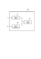
- FIG. 2 is a functional block configuration diagram of the communication control device 50 according to the embodiment of the present invention.
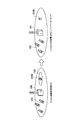
- FIG. 3 is an explanatory diagram of inter-cell interference coordination in the time domain and the frequency domain.
- FIG. 4 is an explanatory diagram of an example of controlling the ABS (RNTP) pattern by the communication control device 50 according to the embodiment of the present invention.
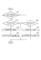
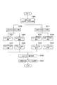
- FIG. 5 is a diagram illustrating an operation flow according to the control example 1 of the ABS (RNTP) pattern by the communication control device 50 according to the embodiment of the present invention.
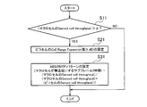
- FIG. 6 is a diagram showing an operation flow according to the control example 2 of the ABS (RNTP) pattern by the communication control device 50 according to the embodiment of the present invention.
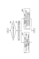
- FIG. 7 is a diagram showing an operation flow according to the control example 3 of the ABS (RNTP) pattern by the communication control device 50 according to the embodiment of the present invention.
- FIG. 8 is a diagram illustrating an operation flow according to the control example 1 of the Cell Range Expansion value by the communication control device 50 according to the embodiment of the present invention.
- FIG. 9 is a diagram showing an operation flow according to the control example 2 of the Cell Range Expansion value by the communication control device 50 according to the embodiment of the present invention.
- FIG. 10 is an explanatory diagram of a third example of Cell Range Expansion value control by the communication control device 50 according to the embodiment of the present invention.
- FIG. 11 is a diagram illustrating an operation flow according to control example 3 of the Cell Range Expansion value by the communication control device 50 according to the embodiment of the present invention.
- FIG. 12 is a diagram showing an operation flow according to an example of transmission power control parameter control by the communication control device 50 according to the embodiment of the present invention.
- FIG. 13 is an explanatory diagram of an example of controlling the pico cell transmission power by the communication control device 50 according to the embodiment of the present invention.
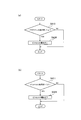
- FIG. 14 is a diagram showing an operation flow according to a control example of pico cell transmission power by the communication control device 50 according to the embodiment of the present invention.
- FIG. 1 is an overall schematic configuration diagram of a mobile communication system 1 according to the present embodiment.
- the mobile communication system 1 includes a communication control device 50, a base station 100, base stations 200A and 200B, and a mobile station 300.
- the mobile communication system 1 is, for example, a mobile communication system according to Long Term Evolution-Advanced (LTE-A), which is being standardized in the 3rd Generation Partnership Project (3GPP).
- LTE-A Long Term Evolution-Advanced
- 3GPP 3rd Generation Partnership Project
- the communication control device 50 controls the base station 100 and the base stations 200A and 200B.
- the communication control device 50 for example, Mobility Management Entity (MME) can be used.
- MME Mobility Management Entity
- the communication control device 50 may be provided inside the base station 100.
- the base station 100 is a macro base station that forms a macro cell.
- the base station 100 constitutes a first base station that forms a macro cell C11 (first cell) having a predetermined cell radius.
- Base stations 200A and 200B are pico base stations that form pico cells (or femto cells).
- the base station 200A constitutes a second base station that forms a pico cell C21 (second cell) having a cell radius smaller than the cell radius of the macro cell C11.
- the base station 200B forms a pico cell C22.
- Base station 200A (200B) may be installed in a building or the like to form a so-called hot spot.
- HetNet which is an overlay network using cells of various forms with different transmission powers
- the mobile station 300 is a terminal device that performs wireless communication with the base station 100 and the base stations 200A and 200B.
- inter-cell interference coordination that avoids interference between the base station 100 and the base stations 200A and 200B is introduced, and the parameters that change depending on the inter-cell interference coordination are autonomously optimized. Turn into.
- FIG. 2 is a functional block configuration diagram of the communication control device 50. As shown in FIG. 2, the communication control device 50 includes a parameter acquisition unit 51, a parameter determination unit 53, and a parameter notification unit 55.
- the parameter acquisition unit 51 acquires parameters used for inter-cell interference coordination. Specifically, the parameter acquisition unit 51 acquires a parameter (first parameter) determined based on the number of mobile stations 300 connected to the macro cell C11 or the number of mobile stations connected to the pico cells C21 and C22.
- the parameter acquisition unit 51 acquires the load factor of the macro cell C11 or the pico cell C21 or C22, the throughput of the macro cell C11 or the pico cell C21 or C22, or the usage rate of the macro cell C11 or the pico cell C21 or C22.
- the first parameter will be described later.
- the parameter determination unit 53 determines a parameter for controlling the base station 100 or the base stations 200A and 200B based on the parameters acquired by the parameter acquisition unit 51. Specifically, the parameter determination unit 53 determines the number of mobile stations 300 connectable to the macro cell C11 or the number of mobile stations 300 connectable to the pico cells C21 and C22 based on the parameters acquired by the parameter acquisition unit 51. A parameter to be changed (second parameter) is determined.
- the parameter determination unit 53 is a time-domain radio resource block allocated to the macro cell C11 or the pico cell C21, C22, a frequency domain radio resource block allocated to the macro cell C11 or the pico cell C21, C22, or the macro cell C11 or the pico cell.
- the transmission power values of C21 and C22 are determined.
- the parameter determining unit 53 determines the ratio of the load ratio between the macro cell C11 and the pico cells C21 and C22, the ratio of the throughput between the macro cell C11 and the pico cells C21 and C22, or the usage rate between the macro cell C11 and the pico cells C21 and C22. Based on the ratio, the size of the radio resource block in the time domain, the size of the radio resource block in the frequency domain, or the value of the transmission power is determined. A more specific parameter determination method will be described later.
- the parameter notification unit 55 notifies the parameter determined by the parameter determination unit 53 to at least one of the base station 100 or the base stations 200A and 200B.
- FIG. 3A is an explanatory diagram of inter-cell interference coordination in the time domain.
- FIG. 3B is an explanatory diagram of inter-cell interference coordination in the frequency domain.
- a radio resource block in the time domain that can be transmitted by the base station 100 (macro base station) in the time domain is defined based on the pattern of Almost Blank Subframe. Is done.
- the base station 100 transmits a radio signal every 1 subframe (1 ms).
- ABS Almost-> Blank-> Subframe
- a radio resource block in the frequency domain that is allocated only to the base station 200A (pico base station) is defined. Specifically, the frequency band f1 is allocated to the macro base station and the pico base station, but the frequency band f2 is allocated only to the pico base station.
- the communication control device 50 uses the parameter acquisition unit 51 to generate an ABS pattern used in inter-cell interference coordination in the time domain and a Relative Narrowband TX Power (RNTP) pattern used in inter-cell interference coordination in the frequency domain. Is autonomously controlled based on the value of the acquired parameter (first parameter).
- RNTP Relative Narrowband TX Power
- the parameter determination unit 53 of the communication control device 50 optimizes the following parameter (second parameter).
- the parameter acquisition unit 51 of the communication control device 50 acquires the following parameter (first parameter) serving as a trigger for executing optimization of the second parameter.
- (A) Load factor of macro cell / pico cell The load factor is expressed by (number of mobile stations connected to the cell / second). When the traffic model is a full buffer model, this corresponds to the ratio of the number of mobile stations (users) connected to the macro cell / pico cell.
- (B) Served cell throughput transmitted by macro cell and pico cell, respectively Served cell throughput is defined in 3GPP TR36.814 as follows.
- Served cell throughput total amount of data for all users / total amount of observation time Considering the traffic model, it is preferable to use Served cell throughput as the parameter.
- ABS (RNTP) usage rate of pico cell ABS (RNTP) usage rate of pico cell
- ABS (RNTP) Pattern First, a control example of the ABS (RNTP) pattern will be described with reference to FIGS.
- FIG. 4 is an explanatory diagram of an example of ABS (RNTP) pattern control by the communication control device 50.
- the communication control device 50 controls the ABS pattern or the RNTP pattern instructing the transmission power of the radio signal in the designated frequency band based on the load factor of the macro cell / pico cell. To do.
- FIG. 4 shows an example in which the Cell Range Expansion value indicating the increase in transmission power for expanding the cell radius of the pico cells C21 and C22 is changed from 4 dB to 12 dB.
- the ratio of the number of users of the macro cell / pico cell is 1: 1 when the Cell Range Expansion value is 4 dB, and the ratio is 3: 7 when the Cell Range Expansion value is 12 dB
- the base station 100 (macro base station ) Is changed from 50% to 70% of the number of subframes that are not transmitted (that is, the number of radio resource blocks (RB)).
- the communication control device 50 selects an ABS pattern that increases the ratio of the number of subframes that the base station 100 (macro base station) does not transmit.
- FIG. 5 shows an operation flow according to the control example 1 of the ABS (RNTP) pattern by the communication control device 50.
- the communication control device 50 determines whether or not the load factor of the macro cell is larger than a predetermined value ⁇ (S10).
- the communication control device 50 determines (S20) the Cell Range Expansion value (for example, 4 dB) of the picocell, and sets the determined Cell Range Expansion value.
- the ABS or RNTP pattern is set based on the number (S30).
- the communication control device 50 uses the formula: (pico cell load factor) / (macro cell load factor) + (pico cell load factor) to calculate the subframe (number of RBs) that the macro cell does not transmit. calculate.
- FIG. 6 shows an operation flow according to the control example 2 of the ABS (RNTP) pattern by the communication control device 50.
- the communication control device 50 controls the ABS pattern or the RNTP pattern based on the Served cell throughput transmitted by each of the macro cell and the pico cell.
- the communication control device 50 determines the cell range expansion value (x dB) of the pico cell by the same processing as in control example 1, and sets the determined cell range expansion value.
- the ABS or RNTP pattern is set based on the number of (S11 to S31).
- the communication control apparatus 50 uses the following formula: (Macro cell Served cell throughput) / (Macro cell Served cell throughput) + (Pico cell Served cell throughput), and the subframe (RB Number).
- FIG. 7 shows an operation flow according to the control example 3 of the ABS (RNTP) pattern by the communication control device 50.
- the communication control device 50 controls the ABS pattern or the RNTP pattern based on the ABS (RNTP) usage rate of the pico cell.
- the communication control device 50 determines the Cell Range Expansion value (x dB) of the picocell by the same process as in Control Example 1, and sets the determined Cell Range Expansion value.
- the ABS or RNTP pattern is set based on the number of (S12 to S32B). For example, if the ABS pattern repeats “1010...”, The ABS usage rate is 50%. Similarly, if the RNTP pattern is “1010...”, The number of RBs transmitted with transmission power exceeding the RNTP threshold is 50%.
- the communication control device 50 uses the formula: (pico cell load factor) / (macro cell load factor) + (pico cell load factor) to calculate the subframe (number of RBs) that the macro cell does not transmit. Calculate (S32A). Alternatively, the communication control device 50 calculates the subframe (number of RBs) that the macro cell does not transmit by using the following formula: (Macro cell Served cell throughput) / (Macro cell Served cell throughput) + (Pico cell Served cell throughput) Calculate (S32B).
- FIG. 8 shows an operation flow according to the control example 1 of the Cell Range Expansion value by the communication control device 50.
- the communication control device 50 controls the cell range expansion value of the pico cell based on the load factor of the macro cell / pico cell. Specifically, when the load factor of the macro cell becomes higher, the Cell Range Expansion value of the pico cell formed in the macro cell is increased, and the traffic (mobile station 300) is offloaded from the macro cell to the pico cell.
- the communication control device 50 determines whether or not the load factors of the macro cell and the pico cell are larger than predetermined values ( ⁇ , ⁇ ) (S110 to S121). Next, the communication control device 50 sets an ABS or RNTP pattern based on the load factor of the macro cell or the pico cell (S130, S131). For example, the pico cell in which the load factor of the macro cell and the load factor of the pico cell are the same Set the Cell Range Expansion value (S140, S141). Note that the Cell Range Expansion value does not have to be the same as the load factor of the macro cell and the load factor of the pico cell, and the difference between the load factor of the macro cell and the load factor of the pico cell is within a predetermined range. A value that becomes
- the communication control device 50 calculates the load factor in the macro cell / pico cell when the Cell Range Expansion value is 4 dB and the load factor in the macro cell / pico cell when the Cell Range Expansion value is 12 dB. Then, the Cell Range Expansion value (for example, 12 dB) of the picocell having the same load factor of the picocell is set.
- FIG. 9 shows an operation flow according to the control example 2 of the Cell Range Expansion value by the communication control device 50.
- the communication control apparatus 50 controls the Cell Range Expansion value of the pico cell based on the Served cell throughput transmitted by the macro cell and the pico cell, respectively.
- the communication control device 50 determines whether or not the Served cell throughput of the macro cell and the pico cell is larger than a predetermined value ( ⁇ , ⁇ ) by processing similar to the control example 1 (S111 to S124).
- the communication control device 50 sets the ABS or RNTP pattern (S133, S134) based on the Served cell throughput of the macro cell or pico cell (S133, S134), for example, the load factor of the macro cell is equal to the load factor of the pico cell.
- Set the Cell Range Expansion value of the pico cell (S143, S144).
- FIG. 10 is an explanatory diagram of a control example 3 of the cell range expansion value by the communication control device 50.
- FIG. 11 shows an operation flow according to the control example 3 of the Cell Range Expansion value by the communication control device 50.
- Control Example 3 when the number of mobile stations 300 located in a specific area (for example, picocell C22) increases, Cell Range Expansion values corresponding to the number of mobile stations 300 are set. In this case, the user throughput at the cell edge is calculated, and the Cell Range Expansion value with the highest throughput is selected.
- a specific area for example, picocell C22
- the communication control device 50 uses a plurality of Cell Range Expansion values (see FIG. 11).
- an Almost-Blank-Subframe pattern is set when 4 dB and 12 dB are set, and user throughput at the cell edge (for example, the cell edge of the pico cell C22) in the setting is calculated (S210 to S230 and S211) ⁇ S231).
- the communication control device 50 compares the calculated values of the plurality of user throughputs (S240), and selects the Cell Range Expansion value that provides the highest throughput (S250).
- the parameter acquisition unit 51 of the communication control device 50 acquires the number of mobile stations 300 connected to the pico cells C21 and C22, and a plurality of Cell Range Expansion values, and the parameter determination unit 53 Based on each Cell Range Expansion value, the throughput (user throughput) of the mobile station 300 located at the cell edge of the cell when the cell radius of the pico cell C21 (C22) is expanded is calculated, and based on the calculated throughput Then, the value of Cell Range Expansion that has the highest throughput among the values of Cell Range Expansion is determined.
- FIG. 12 shows an operation flow according to an example of transmission power control parameter control by the communication control device 50.
- the transmission power control parameter is automatically set based on the maximum throughput reference of the mobile station 300 (user) located in the cell (specifically, the cell edge). Specifically, the transmission power control parameter is set to a value that maximizes the throughput of the user located in the cell (cell edge user).
- the user throughput at the cell edge when the transmission power control parameter is set according to the number of mobile stations 300 is increased.
- a value of a transmission power control parameter that is calculated and has the highest throughput is selected.
- the communication control device 50 uses a plurality of coefficients ⁇ (example shown in FIG. 7). Then, when set to 0.8 and 1.0) and when the transmission power P 0 is set to a predetermined value ( ⁇ 80, ⁇ 85, ⁇ 105, ⁇ 110 dBm), the cell (for example, the pico cell C22) or the cell concerned User throughput at the edge is calculated (S310 to S332 and S311 to S334).
- the communication control device 50 compares the calculated values of a plurality of user throughputs (S340), and selects the transmission power control parameter (transmission power P 0 ) with the highest user throughput (S350).
- the parameter acquisition unit 51 of the communication control device 50 acquires the number of mobile stations 300 connected to the pico cell C21 (C22), and the parameter determination unit 53 moves to connect to the pico cell C21 (C22). Based on the number of stations 300, the radio signal transmission power P 0 candidates from the base station 200A (200B) to the mobile station 300 located in the cell, and the mobile station throughput based on the transmission power (user throughput) ) And a candidate for transmission power with the highest throughput is determined.
- FIG. 13 is an explanatory diagram of an example of controlling the pico cell transmission power by the communication control device 50.
- the communication control apparatus 50 acquires information indicating the load factor of each cell, and controls the transmission power value of the pico cell for the purpose of load distribution among the cells.
- FIGS. 14A and 14B show an operation flow according to an example of control of the transmission power of the pico cell by the communication control device 50.
- FIG. 14A shows an operation flow in the case of turning on the power of the pico cell based on the load factor of the macro cell.
- FIG. 14B shows an operation flow when the power of the pico cell is turned off based on the load factor of the pico cell.
- the communication control device 50 determines whether or not the load factor of the macro cell is larger than a predetermined value ⁇ (S410). When the load factor of the macro cell is larger than ⁇ , the communication control device 50 controls the pico cell so as to turn on the power of the pico cell (S420). As a result, a radio signal is transmitted from the pico cell.
- the communication control device 50 determines whether or not the load factor of the pico cell is smaller than a predetermined value ⁇ (S411).
- the communication control device 50 controls the pico cell so as to turn off the power of the pico cell (S421). As a result, transmission of radio signals from the pico cell is stopped.
- the communication control device 50 sets the transmission power of the base station 200B to 0 and sets the base station 200B to Realize power saving.
- the communication control apparatus 50 may increase the tilt angle of the transmission antenna of the base station 100 (macro base station) when the number of mobile stations 300 connected to the pico cell C22 decreases.
- parameters determined based on the number of mobile stations 300 connected to the macro cell C11 or the number of mobile stations connected to the pico cells C21 and C22 Specifically, the ABS pattern, the RNTP pattern, the cell range expansion value, the transmission power value, and the tilt angle of the transmission antenna are determined. For this reason, it is possible to determine optimal control parameters according to the number of mobile stations 300 connected to the macro cell C11 and the pico cells C21 and C22. That is, according to the mobile communication system 1, it is possible to autonomously optimize parameters that change due to inter-cell interference coordination in a heterogeneous network using cells of various forms having different transmission powers.
- the communication control device 50 has been described as executing the processes according to the flows shown in FIGS. 5 to 9, 11, 12, and 14.
- the changed condition ( The second parameter may be determined using a table in which the first parameter) is associated with the value of the parameter for the condition (second parameter).
- the communication control apparatus 50 sets the Cell Range Expansion value to 8 dB (in the case of three) or without calculating Served cell throughput or the like. It may be set to 12 dB (4 units).
- the mobile communication system according to LTE-A has been described as an example.
- the present invention is not limited to LTE-A, and is not limited to heterogeneous using cells of various forms with different transmission power.
- the present invention can also be applied to other mobile communication systems that perform inter-cell interference coordination in a network.
- the communication control device 50 is provided in the core network.
- the communication control device 50 is provided in the base station 100 to acquire information from the base stations 200A and 200B, and 200A and 200B may be controlled.
- Mobile communication system 50 Communication controller 51 .
- Communication controller 51 ...
- Parameter acquisition unit 53 ...
- Parameter decision unit 55 ...
- Parameter notification unit 100, 200A, 200B ...
- Base station 300 ...
- Mobile station C11 ... Macro cell C21, C22 ... Pico cell
Landscapes
- Engineering & Computer Science (AREA)
- Computer Networks & Wireless Communication (AREA)
- Signal Processing (AREA)
- Quality & Reliability (AREA)
- Mobile Radio Communication Systems (AREA)
Abstract
ヘテロジニアスネットワークにおいてセル間干渉コーディネーションによって変化するパラメータを自律的に最適化できる通信制御装置及び通信制御方法を提供する。通信制御装置50は、第1セルに接続する移動局の数、または第2セルに接続する移動局の数に基づいて定まる第1パラメータとして取得するパラメータ取得部51と、取得された第1パラメータに基づいて、第1セルに接続可能な移動局の数または第2セルに接続可能な移動局の数を変化させるパラメータ決定部53と、決定された第2パラメータを、第1基地局または第2基地局の少なくとも何れかに通知するパラメータ通知部55とを備える。
Description
本発明は、基地局を制御する通信制御装置及び通信制御方法に関し、具体的には、セル間干渉コーディネーションに関するパラメータを制御する通信制御装置及び通信制御方法に関する。
3rd Generation Partnership Project(3GPP)において標準化が進められているLong Term Evolution-Advanced(LTE-A)では、従来のマクロセルに加え、ピコセル、フェムトセル、或いはRemote Radio Head(RRH)など、送信電力の異なる様々な形態のセルを用いたオーバレイ型ネットワークであるヘテロジニアスネットワーク(HetNet)が規定されている(例えば、非特許文献1)。
ヘテロジニアスネットワークでは、移動局のセル選択における受信品質(受信電力)にバイアスを付与することにより、ピコセルなどのセル半径を大きくするCell Range Expansionの適用が規定されている。これにより、マクロセルと、ピコセルなどとがオーバレイされている場合において、より多くのトラフィックをマクロセルからピコセルにオフロードすることが可能となる。
このようなバイアスの付与によってピコセルにハンドオーバした移動局は、本来マクロセルと十分接続が可能な環境下にあるため、マクロセルから大きな干渉を受ける。そこで、セル間における干渉コーディネーション(eICIC)が必要となる。具体的には、マクロセルと、ピコセルとで異なる時間領域または周波数領域の無線リソースを用いることによって、干渉を回避するセル間干渉コーディネーションが知られている。
例えば、時間領域におけるセル間干渉コーディネーションでは、マクロセルに割り当てられる時間領域を制御するAlmost Blank Subframe(ABS)パターンによって、マクロセルが無線信号を送信する時間領域の無線リソースブロックが決定される。
3GPP TS 36.300 V10.3.0, Evolved Universal Terrestrial Radio Access (E-UTRA) and Evolved Universal Terrestrial Radio Access Network (E-UTRAN); Overall description; Stage 2 (Release 10)、2011年3月
しかしながら、上述したセル間干渉コーディネーションには、次のような問題がある。例えば、時間領域におけるセル間干渉コーディネーションの場合、マクロセル及びピコセルに接続する移動局の数に応じた最適なABSパターンが、Cell Range Expansionの値(dB)によって刻々と変化するが、このような場合、最適なABSパターンを決定することができない問題がある。
そこで、本発明は、このような状況に鑑みてなされたものであり、ヘテロジニアスネットワークにおいてセル間干渉コーディネーションによって変化するパラメータを自律的に最適化できる通信制御装置及び通信制御方法の提供を目的とする。
本発明の第1の特徴は、所定のセル半径を有する第1セル(マクロセルC11)を形成する第1基地局(基地局100)と、前記所定のセル半径よりも小さいセル半径を有する第2セル(例えば、ピコセルC21)を形成する第2基地局(例えば、基地局200A)とを制御する通信制御装置(通信制御装置50)であって、前記第1セルに接続する移動局の数、または前記第2セルに接続する移動局の数に基づいて定まる第1パラメータを取得する取得部(パラメータ取得部51)と、前記取得部によって取得された前記第1パラメータに基づいて、前記第1セルに接続可能な移動局の数または前記第2セルに接続可能な移動局の数を変化させる第2パラメータを決定する決定部(パラメータ決定部53)と、前記決定部によって決定された前記第2パラメータを、前記第1基地局または前記第2基地局の少なくとも何れかに通知する通知部(パラメータ通知部55)とを備えることを要旨とする。
本発明の第2の特徴は、所定のセル半径を有する第1セルを形成する第1基地局と、前記所定のセル半径よりも小さいセル半径を有する第2セルを形成する第2基地局とを制御する通信制御方法であって、前記第1セルに接続する移動局の数、または前記第2セルに接続する移動局の数に基づいて定まる第1パラメータを取得するステップと、取得された前記第1パラメータに基づいて、前記第1セルに接続可能な移動局の数または前記第2セルに接続可能な移動局の数を変化させる第2パラメータを決定するステップと、決定された前記第2パラメータを、前記第1基地局または前記第2基地局の少なくとも何れかに通知するステップとを含むことを要旨とする。
次に、本発明の実施形態について説明する。なお、以下の図面の記載において、同一または類似の部分には、同一または類似の符号を付している。ただし、図面は模式的なものであり、各寸法の比率などは現実のものとは異なることに留意すべきである。
したがって、具体的な寸法などは以下の説明を参酌して判断すべきものである。また、図面相互間においても互いの寸法の関係や比率が異なる部分が含まれていることは勿論である。
(1)の全体概略構成
図1は、本実施形態に係る移動体通信システム1の全体概略構成図である。図1に示すように、移動体通信システム1は、通信制御装置50、基地局100、基地局200A, 200B及び移動局300を含む。移動体通信システム1は、例えば、3rd Generation Partnership Project(3GPP)において標準化が進められているLong Term Evolution-Advanced(LTE-A)に従った移動体通信システムである。
図1は、本実施形態に係る移動体通信システム1の全体概略構成図である。図1に示すように、移動体通信システム1は、通信制御装置50、基地局100、基地局200A, 200B及び移動局300を含む。移動体通信システム1は、例えば、3rd Generation Partnership Project(3GPP)において標準化が進められているLong Term Evolution-Advanced(LTE-A)に従った移動体通信システムである。
通信制御装置50は、基地局100及び基地局200A, 200Bを制御する。通信制御装置50としては、例えば、Mobility Management Entity(MME)を用いることができる。或いは、通信制御装置50は、基地局100の内部に設けられても構わない。
基地局100は、マクロセルを形成するマクロ基地局である。基地局100は、所定のセル半径を有するマクロセルC11(第1セル)を形成する第1基地局を構成する。
基地局200A, 200Bは、ピコセル(またはフェムトセル)を形成するピコ基地局である。基地局200Aは、マクロセルC11のセル半径よりも小さいセル半径を有するピコセルC21(第2セル)を形成する第2基地局を構成する。同様に、基地局200Bは、ピコセルC22を形成する。基地局200A(200B)は、建物内などに設置され、いわゆるホットスポットを形成してもよい。
このように、移動体通信システム1では、送信電力の異なる様々な形態のセルを用いたオーバレイ型ネットワークであるヘテロジニアスネットワーク(HetNet)を構成する。
移動局300は、基地局100及び基地局200A, 200Bと無線通信を実行する端末装置である。
また、移動体通信システム1では、基地局100と基地局200A, 200Bとの干渉を回避するセル間干渉コーディネーション(eICIC)が導入されており、セル間干渉コーディネーションによって変化するパラメータを自律的に最適化する。
(2)通信制御装置の機能ブロック構成
図2は、通信制御装置50の機能ブロック構成図である。図2に示すように、通信制御装置50は、パラメータ取得部51、パラメータ決定部53及びパラメータ通知部55を備える。
図2は、通信制御装置50の機能ブロック構成図である。図2に示すように、通信制御装置50は、パラメータ取得部51、パラメータ決定部53及びパラメータ通知部55を備える。
パラメータ取得部51は、セル間干渉コーディネーションに用いられるパラメータを取得する。具体的には、パラメータ取得部51は、マクロセルC11に接続する移動局300の数、またはピコセルC21, C22に接続する移動局の数に基づいて定まるパラメータ(第1パラメータ)を取得する。
本実施形態では、パラメータ取得部51は、マクロセルC11またはピコセルC21, C22の負荷率、マクロセルC11またはピコセルC21, C22のスループット、或いはマクロセルC11またはピコセルC21, C22の使用率を取得する。なお、第1パラメータのさらに具体的な例については、後述する。
パラメータ決定部53は、パラメータ取得部51によって取得されたパラメータに基づいて、基地局100または基地局200A, 200Bを制御するパラメータを決定する。具体的には、パラメータ決定部53は、パラメータ取得部51によって取得されたパラメータに基づいて、マクロセルC11に接続可能な移動局300の数またはピコセルC21, C22に接続可能な移動局300の数を変化させるパラメータ(第2パラメータ)を決定する。
本実施形態では、パラメータ決定部53は、マクロセルC11またはピコセルC21, C22に割り当てられる時間領域の無線リソースブロック、マクロセルC11またはピコセルC21, C22に割り当てられる周波数領域の無線リソースブロック、或いはマクロセルC11またはピコセルC21, C22の送信電力の値を決定する。
具体的には、パラメータ決定部53は、マクロセルC11とピコセルC21, C22との負荷率の比、マクロセルC11とピコセルC21, C22とのスループットの比、またはマクロセルC11とピコセルC21, C22との使用率の比に基づいて、時間領域の無線リソースブロックのサイズ、周波数領域の無線リソースブロックのサイズ、または送信電力の値を決定する。なお、さらに具体的な当該パラメータの決定方法については、後述する。
パラメータ通知部55は、パラメータ決定部53によって決定されたパラメータを、基地局100または基地局200A, 200Bの少なくとも何れかに通知する。
ここで、本実施形態において用いられるパラメータ(第2パラメータ)の一例について説明する。図3(a)は、時間領域におけるセル間干渉コーディネーションの説明図である。図3(b)は、周波数領域におけるセル間干渉コーディネーションの説明図である。
図3(a)に示すように、時間領域におけるセル間干渉コーディネーションでは、Almost Blank Subframeのパターンに基づいて、時間領域において基地局100(マクロ基地局)が送信できる時間領域の無線リソースブロックが規定される。図3(a)に示す例では、「1010…」が繰り返されるパターンであるため、基地局100は、1subframe(1ms)毎に無線信号を送信する。このようなAlmost Blank Subframe(ABS)のパターンが用いられる場合、基地局100と基地局200A, 200Bとが同期して、無線信号の送信タイミングを制御する必要がある。
また、図3(b)に示すように、周波数領域におけるセル間干渉コーディネーションでは、基地局200A(ピコ基地局)のみに割り当てられる周波数領域の無線リソースブロックが規定される。具体的には、周波数帯域f1は、マクロ基地局及びピコ基地局に割り当てられているが、周波数帯域f2は、ピコ基地局のみに割り当てられている。
本実施形態では、通信制御装置50は、時間領域におけるセル間干渉コーディネーションにおいて用いられるABSのパターンや、周波数領域におけるセル間干渉コーディネーションにおいて用いられるRelative Narrowband TX Power (RNTP)パターンを、パラメータ取得部51が取得したパラメータ(第1パラメータ)の値に基づいて自律的に制御する。
(3)制御例
次に、通信制御装置50による基地局100及び基地局200A, 200Bの制御例について説明する。
次に、通信制御装置50による基地局100及び基地局200A, 200Bの制御例について説明する。
本実施形態では、通信制御装置50のパラメータ決定部53は、以下のパラメータ(第2パラメータ)を最適化する。
(a)Almost Blank Subframe (ABS)パターン
(b)Relative Narrowband TX Power(RNTP)パターン
(c)Cell Range expansion値
(d)送信電力(送信電力制御パラメータを含む)
(e)送信アンテナのチルト角
また、通信制御装置50のパラメータ取得部51は、第2パラメータの最適化を実行するトリガーとなる以下のパラメータ(第1パラメータ)を取得する。
(b)Relative Narrowband TX Power(RNTP)パターン
(c)Cell Range expansion値
(d)送信電力(送信電力制御パラメータを含む)
(e)送信アンテナのチルト角
また、通信制御装置50のパラメータ取得部51は、第2パラメータの最適化を実行するトリガーとなる以下のパラメータ(第1パラメータ)を取得する。
(a)マクロセル・ピコセルの負荷率
なお、負荷率は、(当該セルへの接続移動局数/秒)で表現される。トラフィックモデルがフルバッファモデルの場合、マクロセル・ピコセルに接続する移動局(ユーザ)数の比に相当する。
なお、負荷率は、(当該セルへの接続移動局数/秒)で表現される。トラフィックモデルがフルバッファモデルの場合、マクロセル・ピコセルに接続する移動局(ユーザ)数の比に相当する。
(b)マクロセル・ピコセルがそれぞれ送信するServed cell throughput
なお、Served cell throughputは、3GPP TR36.814において以下のように定義されている。
なお、Served cell throughputは、3GPP TR36.814において以下のように定義されている。
Served cell throughput
= total amount of data for all users / total amount of observation time
トラフィックモデルを考慮すると、Served cell throughputを当該パラメータとすることが好ましい。
= total amount of data for all users / total amount of observation time
トラフィックモデルを考慮すると、Served cell throughputを当該パラメータとすることが好ましい。
(c)ピコセルのABS(RNTP)使用率
以下、上述した第1パラメータ及び第2パラメータを用いた通信制御装置50による基地局100及び基地局200A, 200Bの具体的な制御例について説明する。
以下、上述した第1パラメータ及び第2パラメータを用いた通信制御装置50による基地局100及び基地局200A, 200Bの具体的な制御例について説明する。
(3.1)ABS(RNTP)パターン
まず、図4~図7を参照して、ABS(RNTP)パターンの制御例について説明する。
まず、図4~図7を参照して、ABS(RNTP)パターンの制御例について説明する。
(3.1.1)制御例1
図4は、通信制御装置50によるABS(RNTP)パターンの制御例の説明図である。制御例1では、図4に示すように、通信制御装置50は、マクロセル・ピコセルの負荷率に基づいて、ABSパターン、または指定された周波数帯域における無線信号の送信電力を指示するRNTPパターンを制御する。
図4は、通信制御装置50によるABS(RNTP)パターンの制御例の説明図である。制御例1では、図4に示すように、通信制御装置50は、マクロセル・ピコセルの負荷率に基づいて、ABSパターン、または指定された周波数帯域における無線信号の送信電力を指示するRNTPパターンを制御する。
例えば、図4は、ピコセルC21, C22のセル半径を拡張するための送信電力の増加量を示すCell Range Expansion値が4 dBから12 dBに変更になった場合の例を示している。Cell Range Expansion値が4 dBの場合におけるマクロセル/ピコセルのユーザ数比率が1:1、Cell Range Expansion値が12 dB の場合における同比率が3:7であったとすると、基地局100(マクロ基地局)が無送信とするsubframe数(つまり、無線リソースブロック(RB)数)の割合を50%から70%に変化させている。
すなわち、通信制御装置50は、Cell Range Expansion値が高くなった場合、基地局100(マクロ基地局)が無送信とするsubframe数の割合が高くなるようなABSパターンを選択する。
図5は、通信制御装置50によるABS(RNTP)パターンの制御例1に係る動作フローを示す。図5に示すように、通信制御装置50は、マクロセルの負荷率が所定値αよりも大きいか否かを判定する(S10)。マクロセルの負荷率がαよりも大きい場合、通信制御装置50は、ピコセルのCell Range Expansion値(例えば、4 dB)を決定(S20)し、決定したCell Range Expansion値を設定した場合における移動局300の数に基づいて、ABSまたはRNTPのパターンを設定する(S30)。具体的には、通信制御装置50は、数式:(ピコセルの負荷率)/(マクロセルの負荷率)+(ピコセルの負荷率)を用いて、マクロセルが無送信にするサブフレーム(RB数)を計算する。
(3.1.2)制御例2
図6は、通信制御装置50によるABS(RNTP)パターンの制御例2に係る動作フローを示す。制御例2では、通信制御装置50は、マクロセル・ピコセルがそれぞれ送信するServed cell throughputに基づいて、ABSパターンまたはRNTPパターンを制御する。図6に示すように、通信制御装置50は、制御例1と同様に処理により、ピコセルのCell Range Expansion値(x dB)を決定し、決定したCell Range Expansion値を設定した場合における移動局300の数に基づいて、ABSまたはRNTPのパターンを設定する(S11~S31)。
図6は、通信制御装置50によるABS(RNTP)パターンの制御例2に係る動作フローを示す。制御例2では、通信制御装置50は、マクロセル・ピコセルがそれぞれ送信するServed cell throughputに基づいて、ABSパターンまたはRNTPパターンを制御する。図6に示すように、通信制御装置50は、制御例1と同様に処理により、ピコセルのCell Range Expansion値(x dB)を決定し、決定したCell Range Expansion値を設定した場合における移動局300の数に基づいて、ABSまたはRNTPのパターンを設定する(S11~S31)。
具体的には、通信制御装置50は、数式:(マクロセルのServed cell throughput)/(マクロセルのServed cell throughput)+(ピコセルのServed cell throughput)を用いて、マクロセルが無送信にするサブフレーム(RB数)を計算する。
(3.1.3)制御例3
図7は、通信制御装置50によるABS(RNTP)パターンの制御例3に係る動作フローを示す。制御例3では、通信制御装置50は、ピコセルのABS(RNTP)使用率に基づいて、ABSパターンまたはRNTPパターンを制御する。
図7は、通信制御装置50によるABS(RNTP)パターンの制御例3に係る動作フローを示す。制御例3では、通信制御装置50は、ピコセルのABS(RNTP)使用率に基づいて、ABSパターンまたはRNTPパターンを制御する。
図7に示すように、通信制御装置50は、制御例1と同様に処理により、ピコセルのCell Range Expansion値(x dB)を決定し、決定したCell Range Expansion値を設定した場合における移動局300の数に基づいて、ABSまたはRNTPのパターンを設定する(S12~S32B)。例えば、「1010…」が繰り返されるABSパターンであれば、ABSの使用率は50%となる。同様に、「1010…」であるRNTPパターンであれば、RNTP閾値を超える送信電力で送信されるRB数が50%となる。
具体的には、通信制御装置50は、数式:(ピコセルの負荷率)/(マクロセルの負荷率)+(ピコセルの負荷率)を用いて、マクロセルが無送信にするサブフレーム(RB数)を計算する(S32A)。或いは、通信制御装置50は、数式:(マクロセルのServed cell throughput)/(マクロセルのServed cell throughput)+(ピコセルのServed cell throughput)を用いて、マクロセルが無送信にするサブフレーム(RB数)を計算する(S32B)。
(3.2)Cell Range Expansion値
次に、図8~図11を参照して、Cell Range Expansion値の制御例について説明する。
次に、図8~図11を参照して、Cell Range Expansion値の制御例について説明する。
(3.2.1)制御例1
図8は、通信制御装置50によるCell Range Expansion値の制御例1に係る動作フローを示す。制御例1では、通信制御装置50は、マクロセル・ピコセルの負荷率に基づいて、ピコセルのCell Range Expansion値を制御する。具体的には、マクロセルの負荷率が高くなってきた場合、マクロセル内に形成されるピコセルのCell Range Expansion値を高くし、マクロセルからピコセルへトラフィック(移動局300)をオフロードする。
図8は、通信制御装置50によるCell Range Expansion値の制御例1に係る動作フローを示す。制御例1では、通信制御装置50は、マクロセル・ピコセルの負荷率に基づいて、ピコセルのCell Range Expansion値を制御する。具体的には、マクロセルの負荷率が高くなってきた場合、マクロセル内に形成されるピコセルのCell Range Expansion値を高くし、マクロセルからピコセルへトラフィック(移動局300)をオフロードする。
具体的には、図8に示すように、通信制御装置50は、マクロセル及びピコセルの負荷率が、所定値(α、β)よりも大きいか否かを判定する(S110~S121)。次いで、通信制御装置50は、マクロセルまたはピコセルの負荷率に基づいて、ABSまたはRNTPのパターンを設定(S130, S131)し、例えば、マクロセルの負荷率と、ピコセルの負荷率とが同一となるピコセルのCell Range Expansion値を設定する(S140, S141)。なお、Cell Range Expansion値は、マクロセルの負荷率と、ピコセルの負荷率とが必ずしも同一となるような値でなくてもよく、マクロセルの負荷率と、ピコセルの負荷率との差異が所定範囲内になるような値でもよい。
例えば、通信制御装置50は、Cell Range Expansion値が4 dBの場合におけるマクロセル・ピコセルにおける負荷率と、Cell Range Expansion値が12 dBの場合におけるマクロセル・ピコセルにおける負荷率を計算し、マクロセルの負荷率と、ピコセルの負荷率とが同一となるピコセルのCell Range Expansion値(例えば、12 dB)を設定する。
(3.2.2)制御例2
図9は、通信制御装置50によるCell Range Expansion値の制御例2に係る動作フローを示す。制御例2では、通信制御装置50は、マクロセル・ピコセルがそれぞれ送信するServed cell throughputに基づいて、ピコセルのCell Range Expansion値を制御する。
図9は、通信制御装置50によるCell Range Expansion値の制御例2に係る動作フローを示す。制御例2では、通信制御装置50は、マクロセル・ピコセルがそれぞれ送信するServed cell throughputに基づいて、ピコセルのCell Range Expansion値を制御する。
図9に示すように、通信制御装置50は、制御例1と同様に処理により、マクロセル及びピコセルのServed cell throughputが、所定値(α、β)よりも大きいか否かを判定する(S111~S124)。次いで、通信制御装置50は、マクロセルまたはピコセルのServed cell throughputに基づいて、ABSまたはRNTPのパターンを設定(S133, S134)し、例えば、マクロセルの負荷率と、ピコセルの負荷率とが同一となるピコセルのCell Range Expansion値を設定する(S143, S144)。
(3.2.3)制御例3
図10は、通信制御装置50によるCell Range Expansion値の制御例3の説明図である。図11は、通信制御装置50によるCell Range Expansion値の制御例3に係る動作フローを示す。
図10は、通信制御装置50によるCell Range Expansion値の制御例3の説明図である。図11は、通信制御装置50によるCell Range Expansion値の制御例3に係る動作フローを示す。
制御例3では、図10に示すように、特定のエリア(例えば、ピコセルC22)に位置する移動局300の数が多くなった場合、当該移動局300の数に応じたCell Range Expansion値を設定した場合におけるセル端でのユーザスループットがそれぞれ計算され、最もスループットが高くなるCell Range Expansion値が選択される。
具体的には、図11に示すように、移動局300(UE)の分布やピコセル数などの条件が変化した場合(S205)、通信制御装置50は、複数のCell Range Expansion値(図11に示す例では、4 dBと12 dB)に設定した場合におけるAlmost Blank Subframeのパターンを設定し、当該設定におけるセル端(例えば、ピコセルC22のセル端)におけるユーザスループットを計算する(S210~S230及びS211~S231)。
さらに、通信制御装置50は、計算した複数のユーザスループットの値を比較(S240)し、最もスループットが高くなるCell Range Expansion値を選択する(S250)。
すなわち、制御例3では、通信制御装置50のパラメータ取得部51は、ピコセルC21, C22に接続する移動局300の数、及び複数のCell Range Expansion値を取得し、パラメータ決定部53は、複数のCell Range Expansion値のそれぞれに基づいて、ピコセルC21(C22)のセル半径が拡張された場合における当該セルのセル端に位置する移動局300のスループット(ユーザスループット)を計算し、計算したスループットに基づいて、複数のCell Range Expansionの値のうち、当該スループットが最も高くなるCell Range Expansionの値を決定する。
(3.3)送信電力制御パラメータ
図12は、通信制御装置50による送信電力制御パラメータの制御例に係る動作フローを示す。本制御例では、セル内(具体的には、セル端)に位置する移動局300(ユーザ)のスループット最大基準に基づいて、送信電力制御パラメータが自動設定される。具体的には、送信電力制御パラメータとしては、セル内(セル端ユーザ)に位置するユーザのスループットが最大となるような値が設定される。
図12は、通信制御装置50による送信電力制御パラメータの制御例に係る動作フローを示す。本制御例では、セル内(具体的には、セル端)に位置する移動局300(ユーザ)のスループット最大基準に基づいて、送信電力制御パラメータが自動設定される。具体的には、送信電力制御パラメータとしては、セル内(セル端ユーザ)に位置するユーザのスループットが最大となるような値が設定される。
例えば、特定のエリア(例えば、ピコセルC22)に位置する移動局300の数が多くなった場合、当該移動局300の数に応じた送信電力制御パラメータを設定した場合におけるセル端でのユーザスループットがそれぞれ計算され、最もスループットが高くなる送信電力制御パラメータの値が選択される。
具体的には、図12に示すように、移動局300(UE)の分布やピコセル数などの条件が変化した場合(S305)、通信制御装置50は、複数の係数α(図7に示す例では、0.8と1.0)に設定した場合、及び送信電力P0を所定値(-80, -85, -105, -110dBm)に設定した場合において、セル(例えば、ピコセルC22)内、または当該セル端におけるユーザスループットを計算する(S310~S332及びS311~S334)。
さらに、通信制御装置50は、計算した複数のユーザスループットの値を比較(S340)し、最もユーザスループットが高くなる送信電力制御パラメータ(送信電力P0)を選択する(S350)。
すなわち、本制御例では、通信制御装置50のパラメータ取得部51は、ピコセルC21(C22)に接続する移動局300の数を取得し、パラメータ決定部53は、ピコセルC21(C22)に接続する移動局300の数に基づいて、当該セル内に位置する移動局300への基地局200A(200B)からの無線信号の送信電力P0の候補と、当該送信電力に基づく移動局のスループット(ユーザスループット)の候補とを計算し、当該スループットが最も高くなる送信電力の候補を決定する。
(3.4)ピコセル送信電力
図13は、通信制御装置50によるピコセル送信電力の制御例の説明図である。本制御例では、通信制御装置50は、各セルの負荷率を示す情報を取得し、セル間における負荷分散を目的として、ピコセルの送信電力値を制御する。
図13は、通信制御装置50によるピコセル送信電力の制御例の説明図である。本制御例では、通信制御装置50は、各セルの負荷率を示す情報を取得し、セル間における負荷分散を目的として、ピコセルの送信電力値を制御する。
図14(a)及び(b)は、通信制御装置50によるピコセルの送信電力の制御例に係る動作フローを示す。具体的には、図14(a)は、マクロセルの負荷率に基づいて、ピコセルの電源をオンにする場合する場合の動作フローを示す。図14(b)は、ピコセルの負荷率に基づいて、ピコセルの電源をオフにする場合する場合の動作フローを示す。
図14(a)に示すように、通信制御装置50は、マクロセルの負荷率が所定値αよりも大きいか否かを判定する(S410)。マクロセルの負荷率がαよりも大きい場合、通信制御装置50は、ピコセルの電源をオンにするよう当該ピコセルを制御する(S420)。この結果、ピコセルから無線信号が送信される。
また、図14(b)に示すように、通信制御装置50は、ピコセルの負荷率が所定値βよりも小さいか否かを判定する(S411)。ピコセルの負荷率がβよりも小さい場合、通信制御装置50は、ピコセルの電源をオフにするよう当該ピコセルを制御する(S421)。この結果、ピコセルからの無線信号の送信が停止される。
本制御例によれば、図13に示すように、例えば、ピコセルC22に接続する移動局300の数が0の場合、通信制御装置50は、基地局200Bの送信電力を0として基地局200Bのパワーセービングを実現する。
また、通信制御装置50は、ピコセルC22に接続する移動局300の数が減少した場合、基地局100(マクロ基地局)の送信アンテナのチルト角を大きくさせてもよい。
(4)作用・効果の例
以上説明した移動体通信システム1によれば、マクロセルC11に接続する移動局300の数、またはピコセルC21, C22に接続する移動局の数に基づいて定まるパラメータ、具体的には、ABSパターン、RNTPパターン、Cell Range Expansion値、送信電力値及び送信アンテナのチルト角が決定される。このため、マクロセルC11及びピコセルC21, C22に接続する移動局300の数に応じた最適な制御パラメータを決定できる。すなわち、移動体通信システム1によれば、送信電力の異なる様々な形態のセルを用いたヘテロジニアスネットワークにおいてセル間干渉コーディネーションによって変化するパラメータを自律的に最適化できる。
以上説明した移動体通信システム1によれば、マクロセルC11に接続する移動局300の数、またはピコセルC21, C22に接続する移動局の数に基づいて定まるパラメータ、具体的には、ABSパターン、RNTPパターン、Cell Range Expansion値、送信電力値及び送信アンテナのチルト角が決定される。このため、マクロセルC11及びピコセルC21, C22に接続する移動局300の数に応じた最適な制御パラメータを決定できる。すなわち、移動体通信システム1によれば、送信電力の異なる様々な形態のセルを用いたヘテロジニアスネットワークにおいてセル間干渉コーディネーションによって変化するパラメータを自律的に最適化できる。
(5)その他の実施形態
上述したように、本発明の一実施形態を通じて本発明の内容を開示したが、この開示の一部をなす論述及び図面は、本発明を限定するものであると理解すべきではない。この開示から当業者には様々な代替実施の形態が明らかとなろう。
上述したように、本発明の一実施形態を通じて本発明の内容を開示したが、この開示の一部をなす論述及び図面は、本発明を限定するものであると理解すべきではない。この開示から当業者には様々な代替実施の形態が明らかとなろう。
例えば、上述した実施形態では、通信制御装置50は、図5~図9、図11、図12及び図14に示したフローに従った処理を実行するものとして説明したが、変更された条件(第1パラメータ)と、当該条件に対するパラメータ(第2パラメータ)の値とが対応付けられたテーブルを用いて、第2パラメータを決定してもよい。例えば、ピコセルに接続する移動局300の数が3または4台である場合、通信制御装置50は、Served cell throughputなどを計算することなく、Cell Range Expansion値を8 dB(3台の場合)または12 dB(4台)と設定していてもよい。
また、上述した実施形態では、LTE-Aに従った移動体通信システムを例として説明したが、本発明は、LTE-Aに限らず、送信電力の異なる様々な形態のセルを用いたヘテロジニアスネットワークにおいてセル間干渉コーディネーションを実行するような他の移動体通信システムにも勿論適用し得る。
また、上述した実施形態では、通信制御装置50がコアネットワークに設けられる形態としたが、通信制御装置50を基地局100の内部に設け、基地局200A, 200Bから情報を取得するとともに、基地局200A, 200Bを制御するようにしてもよい。
このように、本発明は、ここでは記載していない様々な実施の形態などを含むことは勿論である。したがって、本発明の技術的範囲は、上述の説明から妥当な請求の範囲に係る発明特定事項によってのみ定められるものである。
なお、日本国特許出願第2011-119734号(2011年5月27日出願)の全内容が、参照により、本願明細書に組み込まれている。
本発明の特徴によれば、ヘテロジニアスネットワークにおいてセル間干渉コーディネーションによって変化するパラメータを自律的に最適化できる通信制御装置及び通信制御方法を提供することができる。
1…移動体通信システム
50…通信制御装置
51…パラメータ取得部
53…パラメータ決定部
55…パラメータ通知部
100, 200A, 200B…基地局
300…移動局
C11…マクロセル
C21, C22…ピコセル
50…通信制御装置
51…パラメータ取得部
53…パラメータ決定部
55…パラメータ通知部
100, 200A, 200B…基地局
300…移動局
C11…マクロセル
C21, C22…ピコセル
Claims (5)
- 所定のセル半径を有する第1セルを形成する第1基地局と、前記所定のセル半径よりも小さいセル半径を有する第2セルを形成する第2基地局とを制御する通信制御装置であって、
前記第1セルに接続する移動局の数、または前記第2セルに接続する移動局の数に基づいて定まる第1パラメータを取得する取得部と、
前記取得部によって取得された前記第1パラメータに基づいて、前記第1セルに接続可能な移動局の数または前記第2セルに接続可能な移動局の数を変化させる第2パラメータを決定する決定部と、
前記決定部によって決定された前記第2パラメータを、前記第1基地局または前記第2基地局の少なくとも何れかに通知する通知部と
を備える通信制御装置。 - 前記取得部は、前記第1セルまたは前記第2セルの負荷率、前記第1セルまたは前記第2セルのスループット、或いは前記第1セルまたは前記第2セルの使用率を前記第1パラメータとして取得する請求項1に記載の通信制御装置。
- 前記決定部は、前記第1セルまたは前記第2セルに割り当てられる時間領域の無線リソースブロック、前記第1セルまたは前記第2セルに割り当てられる周波数領域の無線リソースブロック、或いは前記第1セルまたは前記第2セルの送信電力を前記第2パラメータとして決定する請求項1または2に記載の通信制御装置。
- 前記決定部は、前記第1セルと前記第2セルとの負荷率の比、前記第1セルと前記第2セルとのスループットの比、または前記第1セルと前記第2セルとの使用率の比に基づいて、前記時間領域の無線リソースブロックのサイズ、前記周波数領域の無線リソースブロックのサイズ、または前記送信電力の値を決定する請求項3に記載の通信制御装置。
- 所定のセル半径を有する第1セルを形成する第1基地局と、前記所定のセル半径よりも小さいセル半径を有する第2セルを形成する第2基地局とを制御する通信制御方法であって、
前記第1セルに接続する移動局の数、または前記第2セルに接続する移動局の数に基づいて定まる第1パラメータを取得するステップと、
取得された前記第1パラメータに基づいて、前記第1セルに接続可能な移動局の数または前記第2セルに接続可能な移動局の数を変化させる第2パラメータを決定するステップと、
決定された前記第2パラメータを、前記第1基地局または前記第2基地局の少なくとも何れかに通知するステップと
を含む通信制御方法。
Priority Applications (3)
| Application Number | Priority Date | Filing Date | Title |
|---|---|---|---|
| US14/114,699 US9473996B2 (en) | 2011-05-27 | 2012-05-21 | Communication control device and communication control method |
| CN201280020679.XA CN103493528B (zh) | 2011-05-27 | 2012-05-21 | 通信控制装置以及通信控制方法 |
| EP12793188.9A EP2717606A4 (en) | 2011-05-27 | 2012-05-21 | COMMUNICATION CONTROL DEVICE AND COMMUNICATION CONTROL METHOD |
Applications Claiming Priority (2)
| Application Number | Priority Date | Filing Date | Title |
|---|---|---|---|
| JP2011119734A JP5564009B2 (ja) | 2011-05-27 | 2011-05-27 | 通信制御装置及び通信制御方法 |
| JP2011-119734 | 2011-05-27 |
Publications (1)
| Publication Number | Publication Date |
|---|---|
| WO2012165200A1 true WO2012165200A1 (ja) | 2012-12-06 |
Family
ID=47259061
Family Applications (1)
| Application Number | Title | Priority Date | Filing Date |
|---|---|---|---|
| PCT/JP2012/062960 Ceased WO2012165200A1 (ja) | 2011-05-27 | 2012-05-21 | 通信制御装置及び通信制御方法 |
Country Status (5)
| Country | Link |
|---|---|
| US (1) | US9473996B2 (ja) |
| EP (1) | EP2717606A4 (ja) |
| JP (1) | JP5564009B2 (ja) |
| CN (1) | CN103493528B (ja) |
| WO (1) | WO2012165200A1 (ja) |
Cited By (4)
| Publication number | Priority date | Publication date | Assignee | Title |
|---|---|---|---|---|
| US20140119332A1 (en) * | 2012-10-26 | 2014-05-01 | Lg Electronics Inc. | Interference control method in wireless communication system and apparatus for the same |
| CN103945388A (zh) * | 2014-04-16 | 2014-07-23 | 西安交通大学 | 一种异构网络中基于遗传算法的用户接入网络方法 |
| WO2014198232A1 (en) * | 2013-06-13 | 2014-12-18 | Sony Corporation | Interference coordination method, interference coordination device and measurement device |
| JP2015514361A (ja) * | 2012-03-22 | 2015-05-18 | アルカテル−ルーセント | 異種ネットワークでのalmostblanksubframeデューティ・サイクル適合 |
Families Citing this family (15)
| Publication number | Priority date | Publication date | Assignee | Title |
|---|---|---|---|---|
| US9198046B2 (en) * | 2012-10-01 | 2015-11-24 | Nokia Solutions And Networks Oy | Enhanced metrics exchange for a wireless network |
| WO2014073132A1 (ja) * | 2012-11-09 | 2014-05-15 | 日本電気株式会社 | 無線リソース設定方法、基地局、無線リソース設定システム及び非一時的なコンピュータ可読媒体 |
| EP2919501B1 (en) | 2012-11-09 | 2017-12-13 | NEC Corporation | Wireless-resource setting method, base station, wireless-resource setting system, and non-transitory computer-readable medium |
| US9578607B2 (en) | 2013-01-30 | 2017-02-21 | Nec Corporation | Radio communication system, radio station, and method for controlling transmission power |
| CN104244286A (zh) * | 2013-06-20 | 2014-12-24 | 中兴通讯股份有限公司 | 一种动态调整覆盖范围的方法及低功率基站 |
| CN103918303B (zh) * | 2013-09-18 | 2018-11-06 | 华为技术有限公司 | 时域干扰协调方法及网络设备 |
| US9788216B2 (en) * | 2013-09-27 | 2017-10-10 | Avago Technologies General Ip (Singapore) Pte. Ltd. | Method and apparatus for heterogeneous small cells self-organization in LTE networks based on internet protocol multimedia subsystems |
| US10827378B2 (en) | 2013-10-07 | 2020-11-03 | Sony Corporation | Communication control apparatus, communication control method, radio communication apparatus, radio communication method and radio communication system |
| US9591536B2 (en) * | 2013-10-18 | 2017-03-07 | At&T Mobility Ii Llc | Cell user occupancy indicator to enhance intelligent traffic steering |
| US9325467B2 (en) * | 2014-04-10 | 2016-04-26 | Alcatel Lucent | Method and system for controlling almost blank subframes (ABS) based on cell border rate ratios |
| EP3146779B1 (en) * | 2014-05-21 | 2024-04-17 | Altiostar Networks, Inc. | Enhanced inter-cell interference coordination |
| US20150350919A1 (en) * | 2014-05-27 | 2015-12-03 | Qualcomm Incorporated | Adaptation of enhanced inter-cell interference coordination configuration |
| KR102273878B1 (ko) | 2014-07-02 | 2021-07-06 | 삼성전자 주식회사 | 무선 통신 시스템에서 셀 간 부하 분산 방법 및 장치 |
| US9692581B1 (en) * | 2015-02-02 | 2017-06-27 | Sprint Spectrum L.P. | Systems and methods for load and interference coordination in a wireless communication network |
| JP2017092728A (ja) | 2015-11-11 | 2017-05-25 | 富士通株式会社 | 通信システム、基地局、制御局、制御局の制御方法 |
Citations (2)
| Publication number | Priority date | Publication date | Assignee | Title |
|---|---|---|---|---|
| JP2007507152A (ja) * | 2003-09-30 | 2007-03-22 | ユーティースターコム コリア リミテッド | パイロットチャネルの電力を動的に割り当てるための方法 |
| JP2010283440A (ja) * | 2009-06-02 | 2010-12-16 | Nec Corp | 移動通信システム、移動通信方法、基地局制御装置およびプログラム |
Family Cites Families (25)
| Publication number | Priority date | Publication date | Assignee | Title |
|---|---|---|---|---|
| EP0856955A3 (en) * | 1997-01-29 | 2000-09-06 | YRP Mobile Telecommunications Key Technology Research Laboratories Co., Ltd. | CDMA power control system |
| US6253087B1 (en) * | 1998-09-30 | 2001-06-26 | Telefonaktiebolaget Lm Ericsson | Method and system for improved traffic management in wireless telecommunication systems |
| FR2832896B1 (fr) * | 2001-11-28 | 2004-07-23 | Wavecom Sa | Reseau de telecommunication cellulaire mettant en oeuvre des cellules de tailles differentes, station de base, terminal et procede correspondant |
| JP3827634B2 (ja) | 2002-11-29 | 2006-09-27 | Necインフロンティア株式会社 | 無線lan基地局及び無線lan基地局における通信制御方法 |
| JP4024725B2 (ja) | 2003-07-18 | 2007-12-19 | 株式会社東芝 | 移動通信システム、同システムの無線制御局、同システムの基地局、同システムの移動局、および並列組み合わせスペクトラム拡散方式のパラメータ決定方法 |
| US8463282B2 (en) | 2003-12-03 | 2013-06-11 | Qualcomm Incorporated | Overload detection in a wireless communication system |
| US20100144365A1 (en) * | 2006-07-05 | 2010-06-10 | Huanxu Pan | Wireless base station, load distribution apparatus, centralized control apparatus, wireless communication system, load distribution method and load distribution program |
| CN101536563A (zh) * | 2006-11-13 | 2009-09-16 | Lm爱立信电话有限公司 | 无线电信系统 |
| US8175661B2 (en) * | 2007-09-03 | 2012-05-08 | Intel Corporation | Device, system, and method of power saving in wireless network |
| US8391796B2 (en) * | 2008-09-30 | 2013-03-05 | SpiderCloud Wirless, Inc. | Identifying and controlling interference from wireless terminals |
| JP5456695B2 (ja) * | 2008-12-15 | 2014-04-02 | パナソニック株式会社 | 端末装置、基地局装置、通信システムおよびハンドオーバー制御方法 |
| KR101507529B1 (ko) * | 2009-12-08 | 2015-04-07 | 닛본 덴끼 가부시끼가이샤 | 무선 통신 시스템, 기지국 장치, 기지국 제어 장치, 기지국의 송신 전력 제어 방법, 및 컴퓨터 판독 가능 매체 |
| JP5340995B2 (ja) * | 2010-02-26 | 2013-11-13 | 株式会社日立製作所 | 基地局、無線通信システム及び干渉基準のハンドオーバ制御方法 |
| KR101641106B1 (ko) * | 2010-06-09 | 2016-07-20 | 삼성전자주식회사 | 계층 셀에서의 매크로 기지국, 소형 기지국 및 단말의 통신 방법 |
| US20120026972A1 (en) * | 2010-08-02 | 2012-02-02 | Guowang Miao | Apparatus and method for supporting range expansion in a wireless network |
| US9807633B2 (en) * | 2010-11-05 | 2017-10-31 | Google Technology Holdings LLC | Configuring unscheduled periods to enable interference reduction in heterogeneous networks |
| US20120113961A1 (en) * | 2010-11-08 | 2012-05-10 | Motorola Mobility, Inc. | Interference Measurements in Enhanced Inter-Cell Interference Coordination Capable Wireless Terminals |
| US20120122472A1 (en) * | 2010-11-12 | 2012-05-17 | Motorola Mobility, Inc. | Positioning Reference Signal Assistance Data Signaling for Enhanced Interference Coordination in a Wireless Communication Network |
| WO2012100822A1 (en) * | 2011-01-26 | 2012-08-02 | Telefonaktiebolaget L M Ericsson (Publ) | A method and a network node for determining an offset for selection of a cell of a first radio network node |
| US8494467B2 (en) * | 2011-07-12 | 2013-07-23 | Renesas Mobile Corporation | Automatic gain control configuration |
| US9742516B2 (en) * | 2011-07-28 | 2017-08-22 | Blackberry Limited | Method and system for control format detection in heterogeneous cellular networks |
| JP5984346B2 (ja) * | 2011-08-15 | 2016-09-06 | 株式会社Nttドコモ | 無線通信システム、無線基地局装置、ユーザ端末及び無線通信方法 |
| US9253713B2 (en) * | 2011-09-26 | 2016-02-02 | Blackberry Limited | Method and system for small cell discovery in heterogeneous cellular networks |
| US9332474B2 (en) * | 2012-05-17 | 2016-05-03 | Telefonaktiebolaget L M Ericsson | Signaling support for multi sector deployment in cellular communications |
| WO2014044310A1 (en) * | 2012-09-20 | 2014-03-27 | Telefonaktiebolaget L M Ericsson (Publ) | Method and network node for improving resource utilization of a radio cell |
-
2011
- 2011-05-27 JP JP2011119734A patent/JP5564009B2/ja not_active Expired - Fee Related
-
2012
- 2012-05-21 CN CN201280020679.XA patent/CN103493528B/zh not_active Expired - Fee Related
- 2012-05-21 WO PCT/JP2012/062960 patent/WO2012165200A1/ja not_active Ceased
- 2012-05-21 US US14/114,699 patent/US9473996B2/en not_active Expired - Fee Related
- 2012-05-21 EP EP12793188.9A patent/EP2717606A4/en not_active Withdrawn
Patent Citations (2)
| Publication number | Priority date | Publication date | Assignee | Title |
|---|---|---|---|---|
| JP2007507152A (ja) * | 2003-09-30 | 2007-03-22 | ユーティースターコム コリア リミテッド | パイロットチャネルの電力を動的に割り当てるための方法 |
| JP2010283440A (ja) * | 2009-06-02 | 2010-12-16 | Nec Corp | 移動通信システム、移動通信方法、基地局制御装置およびプログラム |
Non-Patent Citations (3)
| Title |
|---|
| 3RD GENERATION PARTNERSHIP PROJECT: "3GPP TS 36.300 V10.3.0, Evolved Universal Terrestrial Radio Access (E-UTRA) and Evolved Universal Terrestrial Radio Access Network (E-UTRAN); Overall description; Stage 2 (Release 10)", March 2011 (2011-03-01) |
| ERICSSON ET AL.: "On data channel performance with cell range expansion and non-full buffer traffic", 3GPP TSG RAN WG1 MEETING #62BIS, R1-105336, October 2010 (2010-10-01), XP050598769 * |
| See also references of EP2717606A4 |
Cited By (10)
| Publication number | Priority date | Publication date | Assignee | Title |
|---|---|---|---|---|
| JP2015514361A (ja) * | 2012-03-22 | 2015-05-18 | アルカテル−ルーセント | 異種ネットワークでのalmostblanksubframeデューティ・サイクル適合 |
| US20140119332A1 (en) * | 2012-10-26 | 2014-05-01 | Lg Electronics Inc. | Interference control method in wireless communication system and apparatus for the same |
| US9398548B2 (en) * | 2012-10-26 | 2016-07-19 | Lg Electronics Inc. | Interference control method in wireless communication system and apparatus for the same |
| WO2014198232A1 (en) * | 2013-06-13 | 2014-12-18 | Sony Corporation | Interference coordination method, interference coordination device and measurement device |
| CN104244335A (zh) * | 2013-06-13 | 2014-12-24 | 索尼公司 | 干扰协调方法、干扰协调装置以及测量装置 |
| US9848393B2 (en) | 2013-06-13 | 2017-12-19 | Sony Corporation | Interference coordination method, interference coordination device and measurement device |
| US10368317B2 (en) | 2013-06-13 | 2019-07-30 | Sony Corporation | Interference coordination method, interference coordination device and measurement device |
| CN104244335B (zh) * | 2013-06-13 | 2019-12-10 | 索尼公司 | 干扰协调方法、干扰协调装置以及测量装置 |
| CN103945388A (zh) * | 2014-04-16 | 2014-07-23 | 西安交通大学 | 一种异构网络中基于遗传算法的用户接入网络方法 |
| CN103945388B (zh) * | 2014-04-16 | 2017-10-20 | 西安交通大学 | 一种异构网络中基于遗传算法的用户接入网络方法 |
Also Published As
| Publication number | Publication date |
|---|---|
| CN103493528A (zh) | 2014-01-01 |
| CN103493528B (zh) | 2017-02-08 |
| JP2012249106A (ja) | 2012-12-13 |
| EP2717606A4 (en) | 2015-11-18 |
| EP2717606A1 (en) | 2014-04-09 |
| US20140162662A1 (en) | 2014-06-12 |
| US9473996B2 (en) | 2016-10-18 |
| JP5564009B2 (ja) | 2014-07-30 |
Similar Documents
| Publication | Publication Date | Title |
|---|---|---|
| JP5564009B2 (ja) | 通信制御装置及び通信制御方法 | |
| CN104170446B (zh) | 用于利用保护子帧的小区间干扰协调的方法和设备 | |
| US10506577B2 (en) | Systems and methods for adaptive transmissions in a wireless network | |
| TWI596966B (zh) | Energy-saving method in mobile communication system | |
| EP2846579B1 (en) | Measurement and transmission method, device and system for interference coordination | |
| EP2712231B1 (en) | Interference coordination method and base station thereof | |
| CA2795976C (en) | Apparatus and method for adaptive transmission during almost blank subframes in a wireless communication network | |
| KR101895108B1 (ko) | 인핸스드 수신기에 관해 병렬 측정을 조정하기 위한 노드 및 방법 | |
| EP2709395A1 (en) | Method for dynamically adjusting subframe in wireless communication system, base station, and system | |
| CN102740436B (zh) | 功率调整方法和基站 | |
| US20140362750A1 (en) | System and method for energy saving in a wireless system | |
| JP2014522215A (ja) | セル結合バイアスおよび/または干渉軽減技法の適用のための自動化されたトリガ | |
| CN104247524A (zh) | 用于异构网络中的灵活时分双工操作的设置和维护框架 | |
| JP2014230272A (ja) | 異種ネットワークにおけるセルハンドオーバ及びアクティブ化 | |
| WO2013168475A1 (ja) | 無線通信システムおよび無線基地局 | |
| WO2014169420A1 (en) | Method and apparatus for management of protected resource in a heterogeneous network | |
| US20160127910A1 (en) | Methods and apparatus for interference management and resource sharing | |
| EP2790430B1 (en) | Picocell range expansion configuration on Authorized Shared Access (ASA) | |
| US9794799B2 (en) | Method and apparatus for performing carrier aggregation using ABS patterns in macro eNB of wireless communication system connected to heterogeneous network | |
| CN106803779A (zh) | 宏微小区间干扰协调方法及装置、基站、通信系统 | |
| CN107889065B (zh) | 一种crs广播方法、干扰协调方法及装置 | |
| Daeinabi et al. | Dynamic Almost Blank Subframe Scheme for Enhanced Intercell Interference Coordination in LTE-A Heterogeneous Networks | |
| KR20180093170A (ko) | 무선 통신 시스템에서의 핸드오버 제어 방법 | |
| JP2014138335A (ja) | 通信制御装置、無線基地局装置および通信制御方法 |
Legal Events
| Date | Code | Title | Description |
|---|---|---|---|
| 121 | Ep: the epo has been informed by wipo that ep was designated in this application |
Ref document number: 12793188 Country of ref document: EP Kind code of ref document: A1 |
|
| WWE | Wipo information: entry into national phase |
Ref document number: 2012793188 Country of ref document: EP |
|
| WWE | Wipo information: entry into national phase |
Ref document number: 14114699 Country of ref document: US |
|
| NENP | Non-entry into the national phase |
Ref country code: DE |