WO2012168963A1 - 電池システムおよび、電池システムの制御方法 - Google Patents
電池システムおよび、電池システムの制御方法 Download PDFInfo
- Publication number
- WO2012168963A1 WO2012168963A1 PCT/JP2011/003205 JP2011003205W WO2012168963A1 WO 2012168963 A1 WO2012168963 A1 WO 2012168963A1 JP 2011003205 W JP2011003205 W JP 2011003205W WO 2012168963 A1 WO2012168963 A1 WO 2012168963A1
- Authority
- WO
- WIPO (PCT)
- Prior art keywords
- relay
- battery
- state
- smr
- system main
- Prior art date
- Legal status (The legal status is an assumption and is not a legal conclusion. Google has not performed a legal analysis and makes no representation as to the accuracy of the status listed.)
- Ceased
Links
Images



Classifications
-
- B—PERFORMING OPERATIONS; TRANSPORTING
- B60—VEHICLES IN GENERAL
- B60L—PROPULSION OF ELECTRICALLY-PROPELLED VEHICLES; SUPPLYING ELECTRIC POWER FOR AUXILIARY EQUIPMENT OF ELECTRICALLY-PROPELLED VEHICLES; ELECTRODYNAMIC BRAKE SYSTEMS FOR VEHICLES IN GENERAL; MAGNETIC SUSPENSION OR LEVITATION FOR VEHICLES; MONITORING OPERATING VARIABLES OF ELECTRICALLY-PROPELLED VEHICLES; ELECTRIC SAFETY DEVICES FOR ELECTRICALLY-PROPELLED VEHICLES
- B60L58/00—Methods or circuit arrangements for monitoring or controlling batteries or fuel cells, specially adapted for electric vehicles
- B60L58/10—Methods or circuit arrangements for monitoring or controlling batteries or fuel cells, specially adapted for electric vehicles for monitoring or controlling batteries
- B60L58/18—Methods or circuit arrangements for monitoring or controlling batteries or fuel cells, specially adapted for electric vehicles for monitoring or controlling batteries of two or more battery modules
-
- B—PERFORMING OPERATIONS; TRANSPORTING
- B60—VEHICLES IN GENERAL
- B60L—PROPULSION OF ELECTRICALLY-PROPELLED VEHICLES; SUPPLYING ELECTRIC POWER FOR AUXILIARY EQUIPMENT OF ELECTRICALLY-PROPELLED VEHICLES; ELECTRODYNAMIC BRAKE SYSTEMS FOR VEHICLES IN GENERAL; MAGNETIC SUSPENSION OR LEVITATION FOR VEHICLES; MONITORING OPERATING VARIABLES OF ELECTRICALLY-PROPELLED VEHICLES; ELECTRIC SAFETY DEVICES FOR ELECTRICALLY-PROPELLED VEHICLES
- B60L53/00—Methods of charging batteries, specially adapted for electric vehicles; Charging stations or on-board charging equipment therefor; Exchange of energy storage elements in electric vehicles
- B60L53/30—Constructional details of charging stations
-
- H—ELECTRICITY
- H01—ELECTRIC ELEMENTS
- H01M—PROCESSES OR MEANS, e.g. BATTERIES, FOR THE DIRECT CONVERSION OF CHEMICAL ENERGY INTO ELECTRICAL ENERGY
- H01M10/00—Secondary cells; Manufacture thereof
- H01M10/42—Methods or arrangements for servicing or maintenance of secondary cells or secondary half-cells
- H01M10/44—Methods for charging or discharging
- H01M10/441—Methods for charging or discharging for several batteries or cells simultaneously or sequentially
-
- H—ELECTRICITY
- H02—GENERATION; CONVERSION OR DISTRIBUTION OF ELECTRIC POWER
- H02H—EMERGENCY PROTECTIVE CIRCUIT ARRANGEMENTS
- H02H9/00—Emergency protective circuit arrangements for limiting excess current or voltage without disconnection
- H02H9/001—Emergency protective circuit arrangements for limiting excess current or voltage without disconnection limiting speed of change of electric quantities, e.g. soft switching on or off
-
- H—ELECTRICITY
- H02—GENERATION; CONVERSION OR DISTRIBUTION OF ELECTRIC POWER
- H02J—ELECTRIC POWER NETWORKS; CIRCUIT ARRANGEMENTS OR SYSTEMS FOR SUPPLYING OR DISTRIBUTING ELECTRIC POWER; SYSTEMS FOR STORING ELECTRIC ENERGY
- H02J7/00—Circuit arrangements for charging or discharging batteries or for supplying loads from batteries
- H02J7/50—Circuit arrangements for charging or discharging batteries or for supplying loads from batteries acting upon multiple batteries simultaneously or sequentially
- H02J7/52—Circuit arrangements for charging or discharging batteries or for supplying loads from batteries acting upon multiple batteries simultaneously or sequentially for charge balancing, e.g. equalisation of charge between batteries
- H02J7/54—Passive balancing, e.g. using resistors or parallel MOSFETs
-
- H—ELECTRICITY
- H02—GENERATION; CONVERSION OR DISTRIBUTION OF ELECTRIC POWER
- H02J—ELECTRIC POWER NETWORKS; CIRCUIT ARRANGEMENTS OR SYSTEMS FOR SUPPLYING OR DISTRIBUTING ELECTRIC POWER; SYSTEMS FOR STORING ELECTRIC ENERGY
- H02J2105/00—Networks for supplying or distributing electric power characterised by their spatial reach or by the load
- H02J2105/30—Networks for supplying or distributing electric power characterised by their spatial reach or by the load the load networks being external to vehicles, i.e. exchanging power with vehicles
- H02J2105/33—Networks for supplying or distributing electric power characterised by their spatial reach or by the load the load networks being external to vehicles, i.e. exchanging power with vehicles exchanging power with road vehicles
- H02J2105/37—Networks for supplying or distributing electric power characterised by their spatial reach or by the load the load networks being external to vehicles, i.e. exchanging power with vehicles exchanging power with road vehicles exchanging power with electric vehicles [EV] or with hybrid electric vehicles [HEV]
-
- H—ELECTRICITY
- H02—GENERATION; CONVERSION OR DISTRIBUTION OF ELECTRIC POWER
- H02J—ELECTRIC POWER NETWORKS; CIRCUIT ARRANGEMENTS OR SYSTEMS FOR SUPPLYING OR DISTRIBUTING ELECTRIC POWER; SYSTEMS FOR STORING ELECTRIC ENERGY
- H02J7/00—Circuit arrangements for charging or discharging batteries or for supplying loads from batteries
- H02J7/60—Circuit arrangements for charging or discharging batteries or for supplying loads from batteries including safety or protection arrangements
- H02J7/663—Circuit arrangements for charging or discharging batteries or for supplying loads from batteries including safety or protection arrangements using battery or load disconnect circuits
-
- Y—GENERAL TAGGING OF NEW TECHNOLOGICAL DEVELOPMENTS; GENERAL TAGGING OF CROSS-SECTIONAL TECHNOLOGIES SPANNING OVER SEVERAL SECTIONS OF THE IPC; TECHNICAL SUBJECTS COVERED BY FORMER USPC CROSS-REFERENCE ART COLLECTIONS [XRACs] AND DIGESTS
- Y02—TECHNOLOGIES OR APPLICATIONS FOR MITIGATION OR ADAPTATION AGAINST CLIMATE CHANGE
- Y02E—REDUCTION OF GREENHOUSE GAS [GHG] EMISSIONS, RELATED TO ENERGY GENERATION, TRANSMISSION OR DISTRIBUTION
- Y02E60/00—Enabling technologies; Technologies with a potential or indirect contribution to GHG emissions mitigation
- Y02E60/10—Energy storage using batteries
-
- Y—GENERAL TAGGING OF NEW TECHNOLOGICAL DEVELOPMENTS; GENERAL TAGGING OF CROSS-SECTIONAL TECHNOLOGIES SPANNING OVER SEVERAL SECTIONS OF THE IPC; TECHNICAL SUBJECTS COVERED BY FORMER USPC CROSS-REFERENCE ART COLLECTIONS [XRACs] AND DIGESTS
- Y02—TECHNOLOGIES OR APPLICATIONS FOR MITIGATION OR ADAPTATION AGAINST CLIMATE CHANGE
- Y02T—CLIMATE CHANGE MITIGATION TECHNOLOGIES RELATED TO TRANSPORTATION
- Y02T10/00—Road transport of goods or passengers
- Y02T10/60—Other road transportation technologies with climate change mitigation effect
- Y02T10/70—Energy storage systems for electromobility, e.g. batteries
-
- Y—GENERAL TAGGING OF NEW TECHNOLOGICAL DEVELOPMENTS; GENERAL TAGGING OF CROSS-SECTIONAL TECHNOLOGIES SPANNING OVER SEVERAL SECTIONS OF THE IPC; TECHNICAL SUBJECTS COVERED BY FORMER USPC CROSS-REFERENCE ART COLLECTIONS [XRACs] AND DIGESTS
- Y02—TECHNOLOGIES OR APPLICATIONS FOR MITIGATION OR ADAPTATION AGAINST CLIMATE CHANGE
- Y02T—CLIMATE CHANGE MITIGATION TECHNOLOGIES RELATED TO TRANSPORTATION
- Y02T10/00—Road transport of goods or passengers
- Y02T10/60—Other road transportation technologies with climate change mitigation effect
- Y02T10/7072—Electromobility specific charging systems or methods for batteries, ultracapacitors, supercapacitors or double-layer capacitors
-
- Y—GENERAL TAGGING OF NEW TECHNOLOGICAL DEVELOPMENTS; GENERAL TAGGING OF CROSS-SECTIONAL TECHNOLOGIES SPANNING OVER SEVERAL SECTIONS OF THE IPC; TECHNICAL SUBJECTS COVERED BY FORMER USPC CROSS-REFERENCE ART COLLECTIONS [XRACs] AND DIGESTS
- Y02—TECHNOLOGIES OR APPLICATIONS FOR MITIGATION OR ADAPTATION AGAINST CLIMATE CHANGE
- Y02T—CLIMATE CHANGE MITIGATION TECHNOLOGIES RELATED TO TRANSPORTATION
- Y02T90/00—Enabling technologies or technologies with a potential or indirect contribution to GHG emissions mitigation
- Y02T90/10—Technologies relating to charging of electric vehicles
- Y02T90/12—Electric charging stations
-
- Y—GENERAL TAGGING OF NEW TECHNOLOGICAL DEVELOPMENTS; GENERAL TAGGING OF CROSS-SECTIONAL TECHNOLOGIES SPANNING OVER SEVERAL SECTIONS OF THE IPC; TECHNICAL SUBJECTS COVERED BY FORMER USPC CROSS-REFERENCE ART COLLECTIONS [XRACs] AND DIGESTS
- Y02—TECHNOLOGIES OR APPLICATIONS FOR MITIGATION OR ADAPTATION AGAINST CLIMATE CHANGE
- Y02T—CLIMATE CHANGE MITIGATION TECHNOLOGIES RELATED TO TRANSPORTATION
- Y02T90/00—Enabling technologies or technologies with a potential or indirect contribution to GHG emissions mitigation
- Y02T90/10—Technologies relating to charging of electric vehicles
- Y02T90/14—Plug-in electric vehicles
Definitions
- the present invention relates to a battery system in which a first battery and a second battery are connected in parallel, and a technique for controlling charging / discharging of the battery system.
- the assembled battery is connected to the load.
- Some battery systems connect a plurality of assembled batteries in parallel, and connect these assembled batteries to a load.
- a relay is provided for each assembled battery. This relay permits charging / discharging of each assembled battery or prohibits charging / discharging.
- the battery system includes a first battery and a second battery that are connected in parallel and charge and discharge.
- the first relay switches between an ON state that allows charging / discharging of the first battery and an OFF state that prohibits charging / discharging of the first battery.
- the second relay switches between an on state that allows charging / discharging of the second battery and an off state that prohibits charging / discharging of the second battery.
- the controller controls the on state and the off state of the first relay and the second relay.
- a controller changes the order which makes a 1st relay and a 2nd relay an ON state, when charging / discharging a 1st battery and a 2nd battery.
- An information output unit that outputs information on the life of the first relay and the second relay can be provided.
- the damage of the first relay and the second relay is estimated, and when the estimated damage reaches the threshold value, the information output unit can be driven.
- the relay that has reached the threshold value in other words, the relay that has reached the end of its life can be notified to the user or the like via the information output unit.
- the first relay and the second relay can be connected to the positive terminals of the first battery and the second battery, respectively, and the third relay can be connected to the negative terminals of the first battery and the second battery.
- each of the first battery and the second battery an assembled battery composed of a plurality of unit cells connected in series can be used.
- the outputs of the first battery and the second battery can be used for traveling of the vehicle.
- the second invention of the present application is a battery system control method.
- the battery system includes a first battery and a second battery that are connected in parallel and charge and discharge, and a first relay and a second relay.
- the first relay switches between an ON state that allows charging / discharging of the first battery and an OFF state that prohibits charging / discharging of the first battery.
- the second relay switches between an on state that allows charging / discharging of the second battery and an off state that prohibits charging / discharging of the second battery.
- the order in which the first relay and the second relay are turned on is changed.
- the relay that is finally switched on is switched between the first relay and the second relay.
- FIG. 3 is a flowchart illustrating the operation of the battery system that is Embodiment 1.
- FIG. 3 is a diagram illustrating a partial configuration of a battery system that is Embodiment 2.
- 6 is a flowchart for explaining the operation of a battery system that is Embodiment 2.
- 6 is a flowchart illustrating the operation of a battery system that is Embodiment 3.
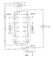
- FIG. 1 is a diagram illustrating a configuration of a battery system.
- the first battery pack (corresponding to the first battery) 10 and the second battery pack (corresponding to the second battery) 20 are connected in parallel.
- the first battery pack 10 has a plurality of single cells 11 connected in series.
- the second battery pack 20 has a plurality of single cells 21 connected in series.
- At least one of the first battery pack 10 and the second battery pack 20 may include a plurality of single cells connected in parallel.
- the number of the single cells 11 constituting the first battery pack 10 and the number of the single cells 21 constituting the second battery pack 20 can be appropriately set in consideration of the required output.
- the number of the unit cells 11 and the unit cells 21 may be equal to each other or may be different from each other.
- cells of the same type can be used.
- different types of cells can be used as the cells 11 and 21.
- a battery that is charged and discharged with a larger current than the unit cell 21 can be used.
- a battery having a larger storage capacity than the unit cell 11 can be used.
- the first battery pack 10 and the second battery pack 20 have service plugs (current breakers) 12 and 22, respectively.
- the service plugs 12 and 22 are used to interrupt the current flowing through the first battery pack 10 and the second battery pack 20. Specifically, the current paths of the battery packs 10 and 20 are interrupted by physically removing the service plugs 12 and 22 from the battery packs 10 and 20.
- Battery packs 10 and 20 have fuses 13 and 23, respectively.
- the system main relay (corresponding to the first relay) SMR-B1 is connected to the positive terminal of the first battery pack 10.
- the system main relay (corresponding to the second relay) SMR-B2 is connected to the positive terminal of the second battery pack 20.
- System main relays SMR-B1 and SMR-B2 are connected in parallel.
- System main relays SMR-B1 and SMR-B2 are switched between ON and OFF in response to a control signal from controller 41.
- the system main relay SMR-B1 When the system main relay SMR-B1 is on, the first battery pack 10 can be charged / discharged. When system main relay SMR-B1 is off, charging / discharging of first battery pack 10 can be prohibited. Further, when the system main relay SMR-B2 is on, the second battery pack 20 can be charged / discharged. When system main relay SMR-B2 is off, charging / discharging of second battery pack 20 can be prohibited.
- the system main relay (corresponding to the third relay) SMR-G is connected to the negative terminals of the first battery pack 10 and the second battery pack 20.
- System main relay SMR-G is switched between on and off in response to a control signal from controller 41.
- the system main relay SMR-G is on, the first battery pack 10 and the second battery pack 20 can be charged / discharged.
- the system main relay SMR-P is connected in series with the limiting resistor 33.
- the system main relay SMR-P and the limiting resistor 33 are connected in parallel with the system main relay SMR-G.
- the limiting resistor 33 is used for suppressing the inrush current from flowing.
- the first battery pack 10 and the second battery pack 20 are connected to a load 42. If system main relays SMR-B1 and SMR-G are on, first battery pack 10 can be connected to load 42. If system main relays SMR-B2 and SMR-G are on, second battery pack 20 can be connected to load.
- the battery packs 10 and 20 can be mounted on a vehicle, for example. Specifically, battery pack 10.20 can be used as a power source for running the vehicle. When the battery packs 10 and 20 are mounted on a vehicle, a motor / generator can be used as the load 42.
- the motor / generator (load) 42 receives electric energy from the battery packs 10 and 20 and can generate kinetic energy for running the vehicle. On the other hand, when the vehicle is decelerated or stopped, the motor / generator (load) 42 can convert kinetic energy generated during braking of the vehicle into electrical energy. The electric energy generated by the motor / generator (load) 42 can be stored in the battery packs 10 and 20 as regenerative power.
- a booster circuit or an inverter can also be arranged between the motor / generator and the battery packs 10 and 20.
- the booster circuit can boost the output voltage of the battery packs 10 and 20.
- the booster circuit can also step down the output voltage of the motor / generator.
- the inverter can convert DC power from the battery packs 10 and 20 into AC power. If an inverter is used, an AC motor can be used as the motor / generator. Here, the inverter can convert AC power from the AC motor into DC power.
- the first monitoring unit 31 monitors the state of the first battery pack 10.
- the state of the first battery pack 10 includes, for example, the voltage, current, and temperature of the first battery pack 10.
- the first monitoring unit 31 has a function of equalizing voltages in the plurality of single cells 11.
- the first monitoring unit 31 detects the voltage of each unit cell 11. When voltage variation occurs in the plurality of unit cells 11, the first monitoring unit 31 can reduce the voltage variation by discharging only the specific unit cell 11.
- the switching element and the resistor are connected in parallel with each unit cell 11, and the first monitoring unit 31 can discharge only the specific unit cell 11 by turning on the switching element.
- the second monitoring unit 32 monitors the state of the second battery pack 20.
- the state of the second battery pack 20 includes, for example, the voltage, current, and temperature of the second battery pack 20.
- the second monitoring unit 32 has a function of equalizing voltages in the plurality of single cells 21.
- the second monitoring unit 32 can have a circuit configuration similar to that of the first monitoring unit 31.
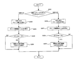
- the operation when controlling charging / discharging of the first battery pack 10 and the second battery pack 20 will be described with reference to the flowchart shown in FIG.
- the process shown in FIG. 2 is a process when the battery packs 10 and 20 are connected to the load 42 in a vehicle on which the battery packs 10 and 20 are mounted.
- the process shown in FIG. 2 is executed by the controller 41.
- step S101 the controller 41 determines whether or not the ignition switch of the vehicle has been switched from OFF to ON. When the ignition switch is switched from OFF to ON, the process proceeds to step S102.
- step S102 the controller 41 determines whether or not the system main relay SMR-B1 was switched from off to on before the system main relay SMR-B2 in the previous process.
- the previous process is the process most recently performed among the processes performed when the ignition switch is switched from OFF to ON (the process illustrated in FIG. 2).
- step S103 when the system main relay SMR-B1 is switched from off to on before the system main relay SMR-B2, the process proceeds to step S103, and otherwise, the process proceeds to step S108.
- Information indicating which of the system main relays SMR-B1 and SMR-B2 was switched from OFF to ON first can be stored in a memory 41a (see FIG. 1) built in the controller 41.
- the memory 41 a is built in the controller 41, but the memory 41 a can be arranged outside the controller 41.
- step S103 the controller 41 switches the system main relay SMR-B2 from off to on.
- the system main relay SMR-B1 remains off.
- step S104 the controller 41 switches the system main relays SMR-P and SMR-B1 from off to on. Thereby, the first battery pack 10 and the second battery pack 20 are connected to the load 42.
- the charging / discharging current of the battery packs 10 and 20 flows through the limiting resistor 33.
- step S105 the controller 41 switches the system main relay SMR-G from off to on, and in step S106 switches the system main relay SMR-P from on to off.
- the connection of the battery packs 10 and 20 and the load 42 is completed. If the electric power of the battery packs 10 and 20 is supplied to the load (motor / generator) 42, the vehicle can be driven. Further, during braking of the vehicle, the battery packs 10 and 20 can store electric power from the load (motor / generator) 42.
- step S107 the controller 41 stores information indicating that the system main relay SMR-B2 is turned on before the system main relay SMR-B1 in the memory 41a.
- the information stored in the memory 41a is updated each time the ignition switch is switched from off to on.
- the information stored in the memory 41a is used in the process of step S102 when the ignition switch is switched from OFF to ON next time.
- step S108 the controller 41 switches the system main relay SMR-B1 from off to on.
- the system main relay SMR-B2 remains off.
- step S109 the controller 41 switches the system main relays SMR-P and SMR-B2 from off to on. Thereby, the first battery pack 10 and the second battery pack 20 are connected to the load 42.
- the charging / discharging current of the battery packs 10 and 20 flows through the limiting resistor 33.
- step S110 the controller 41 switches the system main relay SMR-G from off to on, and in step S111, switches the system main relay SMR-P from on to off. Thereby, connection of the battery packs 10 and 20 and the load 42 is completed.
- step S112 the controller 41 stores in the memory 41a information indicating that the system main relay SMR-B1 is turned on before the system main relay SMR-B2.
- the information stored in the memory 41a is updated each time the ignition switch is switched from off to on.
- the information stored in the memory 41a is used in the process of step S102 when the ignition switch is switched from OFF to ON next time.
- OCV Open Circuit Voltage
- CCV OCV + IR (1)
- I indicates the current flowing through each battery pack 10, 20, and R indicates the internal resistance of each battery pack 10.20.
- the OCVs of the battery packs 10 and 20 may be different from each other according to variations in the self-discharge characteristics of the battery packs 10 and 20. For example, when the battery packs 10 and 20 are left for a long period of time, a difference is likely to occur in the OCV of the battery packs 10 and 20.
- the first monitoring unit 31 and the second monitoring unit 32 are provided for the first battery pack 10 and the second battery pack 20, respectively. For this reason, in each of the 1st battery pack 10 and the 2nd battery pack 20, the equalization process by the monitoring units 31 and 32 is performed separately. Due to the independent equalization process, the OCVs of the battery packs 10 and 20 may be different from each other.
- the order of switching the system main relays SMR-B1 and SMR-B2 from OFF to ON is changed. Specifically, the system main relays SMR-B1 and SMR-B2 are alternately switched as system main relays that are finally switched from off to on each time the ignition switch is switched on.
- the thermal load due to the inrush current can be distributed to both the system main relays SMR-B1 and SMR-B2.
- dispersing the thermal load it is possible to prevent the thermal load from being concentrated on one system main relay, and it is possible to suppress the life reduction due to the thermal load.
- system main relays SMR-B1 and SMR-B2 are connected to the positive terminals of battery packs 10 and 20, respectively, and system main relays SMR-P and SMR- are connected to the negative terminals of battery packs 10 and 20, respectively.
- G is connected, it is not restricted to this.
- system main relays SMR-B1 and SMR-B2 can be connected to the negative terminals of battery packs 10 and 20, respectively, and system main relays SMR-P and SMR-G can be connected to the positive terminals of battery packs 10 and 20. it can.
- system main relays SMR-B1 and SMR-B2 are alternately changed as system main relays that are finally switched from OFF to ON, but the present invention is not limited to this. That is, when the ignition switch is turned on a predetermined number of times, the number of times the system main relay SMR-B1 is finally turned on is equal to the number of times the system main relay SMR-B2 is turned on last. Good. Therefore, the process in which the system main relay SMR-B1 or the system main relay SMR-B2 is finally turned on may be performed continuously.
- the system main relay SMR-B2 and the system main relay SMR-B1 can be switched on in order in accordance with the first and second ignition switches being turned on. Then, the system main relay SMR-B1 and the system main relay SMR-B2 can be switched on in order in response to the third and fourth ignition switches being turned on.
- the number of times the ignition switch is turned on is the fourth time
- the number of times the system main relay SMR-B1 is turned on last is equal to the number of times the system main relay SMR-B2 is turned on last.
- two battery packs 10 and 20 are used, but three or more battery packs can be used. That is, three or more battery packs can be connected in parallel. Even when three or more battery packs are used, system main relays corresponding to the system main relays SMR-B1 and SMR-B2 are connected to these battery packs.
- the system main relays that are switched from OFF to ON may be changed in order.
- the relay that is finally switched from OFF to ON is changed in the order of the first relay, the second relay, and the third relay. can do.
- the ignition switch is turned on a predetermined number of times, the number of times each of the first relay, the second relay, and the third relay is turned on last may be made equal to each other.
- FIG. 3 is a diagram illustrating a partial configuration of the battery system according to the present embodiment. Constituent elements having the same functions as those described in the first embodiment are denoted by the same reference numerals, and detailed description thereof is omitted. In the present embodiment, differences from the first embodiment will be mainly described.
- the controller 41 estimates the damage integrated amounts D1_total and D2_total of the system main relays SMR-B1 and SMR-B2, respectively.
- the system main relays SMR-B1 and SMR-B2 are damaged by a thermal load when an inrush current flows.
- damage is accumulated in the system main relays SMR-B1 and SMR-B2. The accumulation of this damage becomes the damage integrated amount D1_total, D2_total.
- the controller 41 prompts replacement of the system main relays SMR-B1 and SMR-B2.
- the threshold value Dth is a value set in advance in consideration of the lifetime of the system main relays SMR-B1 and SMR-B2.
- the controller 41 outputs a control signal to the information output unit 43 when the damage integrated amounts D1_total, D2_total of the system main relays SMR-B1, SMR-B2 reach the threshold value Dth.
- the information output unit 43 outputs information that prompts replacement of the system main relays SMR-B1 and SMR-B2.
- the information output unit 43 only needs to be able to notify the user or the like of information that prompts replacement of the system main relays SMR-B1 and SMR-B2.
- a lamp, a display, or a speaker can be used as the information output unit 43.
- the controller 41 can turn on the lamp when the damage integrated amounts D1_total and D2_total reach the threshold value Dth.
- the controller 41 can display on the display the content for prompting replacement of the system main relays SMR-B1 and SMR-B2.
- the display content of the display may be any content that prompts the user to replace the system main relays SMR-B1 and SMR-B2. Characters and symbols can be used as appropriate for the display content.
- the controller 41 can cause the speaker to output a content prompting replacement of the system main relays SMR-B1 and SMR-B2 as sound.
- the specific content of the voice can be set as appropriate.
- FIG. 4 is a flowchart showing the operation of the battery system of the present embodiment.
- the process shown in FIG. 4 is executed by the controller 41.
- the process shown in FIG. 4 can be performed after the process shown in FIG. 2 is completed, for example.
- step S201 the controller 41 determines which of the system main relays SMR-B1 and SMR-B2 is the system main relay that was last switched on. If the system main relay that was switched on last is the system main relay SMR-B1, the process proceeds to step S202, and if it is the system main relay SMR-B2, the process proceeds to step S206.
- step S202 the controller 41 calculates the damage amount D1 of the system main relay SMR-B1.
- the damage amount D1 is the amount of damage that the system main relay SMR-B receives when the system main relay SMR-B1 is switched on.
- the damage amount D1 can be calculated (estimated), for example, by any of the three methods described below. Note that the method of calculating the damage amount D1 is not limited to the method described below. That is, any method can be adopted as long as the amount of damage caused by a thermal load can be specified.
- a voltage V between terminals of the system main relay SMR-B1 and a current value I flowing through the system main relay SMR-B1 are measured.
- the voltage V corresponds to the difference between the total voltage of the first battery pack 10 and the total voltage of the second battery pack 20 before the system main relay SMR-B1 is switched on.
- the damage amount D1 can be calculated based on the following formula (2).
- t represents time.
- I (t) indicates a change in the current value I with respect to time.
- V (t) indicates a change in voltage V with respect to time.
- the voltage V between terminals of the system main relay SMR-B1 is measured.
- the voltage V corresponds to the difference between the total voltage of the first battery pack 10 and the total voltage of the second battery pack 20 before the system main relay SMR-B1 is switched on.
- the relationship between the voltage V and the damage amount D1 is specified in advance and stored in the memory 41a as a map. If the map and the measured voltage V are used, the damage amount D1 can be specified.
- the temperature parameter can be included in the map. That is, if the temperature and voltage V are specified, a map that can specify the damage amount D1 can be created in advance.
- the peak current Ipeak flowing through the system main relay SMR-B1 is measured.
- the damage amount D1 can be calculated based on the following formula (3).
- t represents time.
- I (t) indicates a change in the current value I with respect to time.
- V (t) indicates a change in voltage V with respect to time.
- step S203 the controller 41 calculates an integrated damage amount D1_total of the system main relay SMR-B1. Specifically, the controller 41 calculates the current damage integrated amount D1_total by adding the damage amount D1 calculated in step S202 to the damage integrated amount D1_total calculated so far.
- step S204 the controller 41 determines whether or not the integrated damage amount D1_total calculated in step S203 is larger than the threshold value Dth. When the damage integrated amount D1_total is larger than the threshold value Dth, the process proceeds to step S205. Otherwise, the process is terminated.
- step S205 the controller 41 determines that the system main relay SMR-B1 has reached the end of its life, and drives the information output unit 43. Based on the output of the information output unit 43, the user can recognize that the system main relay SMR-B1 has reached the end of its life.
- step S206 the controller 41 calculates the damage amount D2 of the system main relay SMR-B2.
- the method for calculating the damage amount D2 is the same as the method for calculating the damage amount D1.
- step S207 the controller 41 calculates an integrated damage amount D2_total of the system main relay SMR-B2. Specifically, the controller 41 calculates the current damage integrated amount D2_total by adding the damage amount D2 calculated in step S206 to the damage integrated amount D2_total calculated so far.
- step S208 the controller 41 determines whether or not the integrated damage amount D2_total calculated in step S207 is larger than the threshold value Dth.
- the process proceeds to step S209. Otherwise, the process ends.
- step S209 the controller 41 determines that the system main relay SMR-B2 has reached the end of its life and drives the information output unit 43. Based on the output of the information output unit 43, the user can recognize that the system main relay SMR-B2 has reached the end of its life.
- the lifetime of the system main relays SMR-B1 and SMR-B2 can be determined by calculating the damage integrated amounts D1_total and D2_total of the system main relays SMR-B1 and SMR-B2.
- the system main relays SMR-B1 and SMR-B2 can be exchanged according to the life of the system main relays SMR-B1 and SMR-B2.
- a battery system that is Embodiment 3 of the present invention will be described. Constituent elements having the same functions as those described in the first embodiment are denoted by the same reference numerals, and detailed description thereof is omitted. In the present embodiment, differences from the first and second embodiments will be mainly described.
- FIG. 5 is a flowchart for explaining processing of the battery system of the present embodiment. The process shown in FIG. 5 is executed by the controller 41.
- step S301 the controller 41 calculates the damage integrated amounts D1_total and D2_total of the system main relays SMR-B1 and SMR-B2, respectively.
- the damage integrated amounts D1_total and D2_total can be calculated by the method described in the second embodiment.
- step S302 the controller 41 determines whether or not the damage integrated amount D1_total is larger than the damage integrated amount D2_total.
- the controller 41 determines that the system main relay SMR-B1 is deteriorated more than the system main relay SMR-B2, and proceeds to the process of step S303.
- the controller 41 determines that the system main relay SMR-B2 is deteriorated more than the system main relay SMR-B1, and proceeds to the process of step S304.
- step S303 the controller 41 sets the system main relay SMR-B2 as the system main relay that is finally turned on. This setting information is stored in the memory 41a.
- the controller 41 switches on the system main relay SMR-B2 after switching on the system main relay SMR-B1 based on the setting information stored in the memory 41a. Switch to. That is, among the system main relays SMR-B1 and SMR-B2, the one that is switched on last is the system main relay SMR-B2.
- step S304 the controller 41 sets the system main relay SMR-B1 as the system main relay that is finally turned on. This setting information is stored in the memory 41a.
- the controller 41 switches on the system main relay SMR-B1 after switching on the system main relay SMR-B2 based on the setting information stored in the memory 41a. Switch to. That is, among the system main relays SMR-B1 and SMR-B2, the one that is switched on last is the system main relay SMR-B1.
- the system main relay that is finally turned on is changed according to the deterioration state of the system main relays SMR-B1 and SMR-B2.
- variations in deterioration in the system main relays SMR-B1 and SMR-B2 can be suppressed.
- damage can be distributed to system main relays SMR-B1 and SMR-B2, and the life of system main relays SMR-B1 and SMR-B2 can be extended.
Landscapes
- Engineering & Computer Science (AREA)
- Power Engineering (AREA)
- Mechanical Engineering (AREA)
- Transportation (AREA)
- General Chemical & Material Sciences (AREA)
- Electrochemistry (AREA)
- Chemical Kinetics & Catalysis (AREA)
- Chemical & Material Sciences (AREA)
- Manufacturing & Machinery (AREA)
- Life Sciences & Earth Sciences (AREA)
- Sustainable Development (AREA)
- Sustainable Energy (AREA)
- Charge And Discharge Circuits For Batteries Or The Like (AREA)
- Secondary Cells (AREA)
- Electric Propulsion And Braking For Vehicles (AREA)
Abstract
Description
ここで、Iは、各電池パック10,20に流れる電流を示し、Rは、各電池パック10.20の内部抵抗を示す。

式(2)において、tは時間を示す。I(t)は、時間に対する電流値Iの変化を示す。V(t)は、時間に対する電圧Vの変化を示す。

式(3)において、tは時間を示す。I(t)は、時間に対する電流値Iの変化を示す。V(t)は、時間に対する電圧Vの変化を示す。
Claims (11)
- 並列に接続され、充放電を行う第1電池および第2電池と、
前記第1電池の充放電を許容するオン状態と、前記第1電池の充放電を禁止するオフ状態の間で切り替わる第1リレーと、
前記第2電池の充放電を許容するオン状態と、前記第2電池の充放電を禁止するオフ状態の間で切り替わる第2リレーと、
前記第1リレーおよび前記第2リレーのオン状態およびオフ状態を制御するコントローラと、を有し、
前記コントローラは、前記第1電池および前記第2電池の充放電を行うときに、前記第1リレーおよび前記第2リレーをオン状態にする順序を変更することを特徴とする電池システム。 - 前記コントローラは、前記第1電池および前記第2電池の充放電を行うたびに、前記第1リレーおよび前記第2リレーをオン状態にする順序を変更することを特徴とする請求項1に記載の電池システム。
- 前記コントローラは、
オフ状態である前記第1リレーおよび前記第2リレーの端子間電圧に基づいて、前記第1リレーおよび前記第2リレーをオフ状態からオン状態に切り替えたときの熱的負荷によるダメージを推定し、
前記第1電池および前記第2電池の充放電を行うときに、前記第1リレーおよび前記第2リレーのうち、推定したダメージが小さい側のリレーを最後にオン状態に切り替えることを特徴とする請求項1に記載の電池システム。 - 前記第1リレーおよび前記第2リレーの寿命に関する情報を出力する情報出力部を有しており、
前記コントローラは、
オフ状態である前記第1リレーおよび前記第2リレーの端子間電圧に基づいて、前記第1リレーおよび前記第2リレーをオフ状態からオン状態に切り替えたときの熱的負荷によるダメージを推定し、
推定したダメージが閾値に到達したとき、前記情報出力部を駆動することを特徴とする請求項1から3のいずれか1つに記載の電池システム。 - 前記第1電池および前記第2電池の充放電を許容するオン状態と、前記第1電池および前記第2電池の充放電を禁止するオフ状態の間で切り替わる第3リレーを有しており、
前記コントローラは、前記第3リレーのオン状態およびオフ状態を制御することを特徴とする請求項1から4のいずれか1つに記載の電池システム。 - 前記第1電池および前記第2電池のそれぞれは、直列に接続された複数の単電池で構成された組電池であることを特徴とする請求項1から5のいずれか1つに記載の電池システム。
- 前記第1電池および前記第2電池は、車両の走行に用いられるエネルギを出力することを特徴とする請求項6に記載の電池システム。
- 並列に接続され、充放電を行う第1電池および第2電池と、前記第1電池の充放電を許容するオン状態と、前記第1電池の充放電を禁止するオフ状態の間で切り替わる第1リレーと、前記第2電池の充放電を許容するオン状態と、前記第2電池の充放電を禁止するオフ状態の間で切り替わる第2リレーとを有する電池システムの制御方法であって、
前記第1電池および前記第2電池の充放電を行うときに、前記第1リレーおよび前記第2リレーをオン状態にする順序を変更することを特徴とする制御方法。 - 前記第1電池および前記第2電池の充放電を行うたびに、前記第1リレーおよび前記第2リレーをオン状態にする順序を変更することを特徴とする請求項8に記載の制御方法。
- オフ状態である前記第1リレーおよび前記第2リレーの端子間電圧に基づいて、前記第1リレーおよび前記第2リレーをオフ状態からオン状態に切り替えたときの熱的負荷によるダメージを推定し、
前記第1電池および前記第2電池の充放電を行うときに、前記第1リレーおよび前記第2リレーのうち、推定したダメージが小さい側のリレーを最後にオン状態に切り替えることを特徴とする請求項8に記載の制御方法。 - オフ状態である前記第1リレーおよび前記第2リレーの端子間電圧に基づいて、前記第1リレーおよび前記第2リレーをオフ状態からオン状態に切り替えたときの熱的負荷によるダメージを推定し、
推定したダメージが閾値に到達したとき、前記第1リレーおよび前記第2リレーの寿命に関する情報を出力する、
ことを特徴とする請求項8から10のいずれか1つに記載の制御方法。
Priority Applications (5)
| Application Number | Priority Date | Filing Date | Title |
|---|---|---|---|
| JP2012533159A JP5440708B2 (ja) | 2011-06-07 | 2011-06-07 | 電池システムおよび、電池システムの制御方法 |
| EP11867297.1A EP2720344B1 (en) | 2011-06-07 | 2011-06-07 | Battery system, and method for controlling battery system |
| US13/581,298 US9211800B2 (en) | 2011-06-07 | 2011-06-07 | Battery system and control method of battery system |
| CN201180022192.0A CN102934316B (zh) | 2011-06-07 | 2011-06-07 | 电池系统以及电池系统的控制方法 |
| PCT/JP2011/003205 WO2012168963A1 (ja) | 2011-06-07 | 2011-06-07 | 電池システムおよび、電池システムの制御方法 |
Applications Claiming Priority (1)
| Application Number | Priority Date | Filing Date | Title |
|---|---|---|---|
| PCT/JP2011/003205 WO2012168963A1 (ja) | 2011-06-07 | 2011-06-07 | 電池システムおよび、電池システムの制御方法 |
Publications (1)
| Publication Number | Publication Date |
|---|---|
| WO2012168963A1 true WO2012168963A1 (ja) | 2012-12-13 |
Family
ID=47295575
Family Applications (1)
| Application Number | Title | Priority Date | Filing Date |
|---|---|---|---|
| PCT/JP2011/003205 Ceased WO2012168963A1 (ja) | 2011-06-07 | 2011-06-07 | 電池システムおよび、電池システムの制御方法 |
Country Status (5)
| Country | Link |
|---|---|
| US (1) | US9211800B2 (ja) |
| EP (1) | EP2720344B1 (ja) |
| JP (1) | JP5440708B2 (ja) |
| CN (1) | CN102934316B (ja) |
| WO (1) | WO2012168963A1 (ja) |
Cited By (10)
| Publication number | Priority date | Publication date | Assignee | Title |
|---|---|---|---|---|
| JP2013240142A (ja) * | 2012-05-11 | 2013-11-28 | Toyota Industries Corp | 組電池の接続方法および組電池 |
| EP2963728A4 (en) * | 2013-02-26 | 2016-11-16 | Hitachi Ltd | POWER SOURCE DEVICE |
| JPWO2014162686A1 (ja) * | 2013-04-03 | 2017-02-16 | パナソニックIpマネジメント株式会社 | バッテリーシステム |
| JP2019009995A (ja) * | 2015-11-18 | 2019-01-17 | NExT−e Solutions株式会社 | 制御装置、蓄電装置及び蓄電システム |
| CN110718953A (zh) * | 2019-11-11 | 2020-01-21 | 广州极飞科技有限公司 | 一种充电电路与充电系统 |
| JP2020174442A (ja) * | 2019-04-09 | 2020-10-22 | トヨタ自動車株式会社 | 電源システムおよびその制御方法 |
| JP2021072676A (ja) * | 2019-10-29 | 2021-05-06 | 京セラ株式会社 | 蓄電システムおよび管理方法 |
| US11482869B2 (en) | 2018-10-19 | 2022-10-25 | Next-E Solutions Inc. | Electric storage system |
| US11552483B2 (en) | 2018-10-05 | 2023-01-10 | Next-E Solutions Inc. | Electric storage system |
| JP2023511614A (ja) * | 2020-01-28 | 2023-03-20 | ザ・ノコ・カンパニー | 強化された(ターボ)ブーストモードを有するジャンプスタート装置 |
Families Citing this family (24)
| Publication number | Priority date | Publication date | Assignee | Title |
|---|---|---|---|---|
| WO2012101771A1 (ja) * | 2011-01-26 | 2012-08-02 | 株式会社 日立製作所 | 電動車両用蓄電システム |
| KR101219240B1 (ko) * | 2011-01-31 | 2013-01-08 | 로베르트 보쉬 게엠베하 | 배터리 팩 |
| CN103563206A (zh) * | 2011-06-03 | 2014-02-05 | 丰田自动车株式会社 | 蓄电系统 |
| DE102012205260A1 (de) * | 2012-03-30 | 2013-10-02 | Robert Bosch Gmbh | Elektrisches Gerät und Verfahren zum Betreiben eines elektrischen Geräts |
| KR101775547B1 (ko) * | 2013-01-16 | 2017-09-06 | 삼성에스디아이 주식회사 | 이종 셀을 포함하는 배터리 팩 및 이를 포함하는 전력 장치 |
| WO2016185536A1 (ja) * | 2015-05-18 | 2016-11-24 | 日産自動車株式会社 | 蓄電装置及び接続制御方法 |
| CN106233915B (zh) * | 2015-06-03 | 2020-05-26 | 南京德朔实业有限公司 | 电动工具及其控制方法 |
| TWI568122B (zh) * | 2015-11-09 | 2017-01-21 | 財團法人工業技術研究院 | 電池系統與其控制方法 |
| EP3943335B1 (en) * | 2016-11-30 | 2024-05-15 | Bombardier Recreational Products Inc. | Method for energizing an electric system |
| JP6805792B2 (ja) * | 2016-12-14 | 2020-12-23 | 株式会社デンソー | 電池パック |
| GB201705518D0 (en) * | 2017-04-05 | 2017-05-17 | Siemens Ag | Energy storage module |
| US10992144B2 (en) * | 2017-05-17 | 2021-04-27 | Galley Power LLC | Battery balancing and current control with bypass circuit for load switch |
| TWI649939B (zh) | 2017-07-07 | 2019-02-01 | 財團法人工業技術研究院 | 電源裝置運作方法、電源裝置及電源裝置管理系統 |
| KR102308299B1 (ko) * | 2017-11-06 | 2021-10-01 | 주식회사 엘지에너지솔루션 | 셀 모듈 균등화 및 프리차지 장치 및 방법 |
| CN109873465B (zh) * | 2017-12-04 | 2022-06-14 | 财团法人车辆研究测试中心 | 多电源供电分配系统及其分配方法 |
| US10389167B2 (en) * | 2017-12-26 | 2019-08-20 | Automotive Research & Testing Center | Power distribution system using multiple rechargeable power sources and method for distributing power using multiple rechargeable power sources |
| CN115916575B (zh) * | 2020-09-29 | 2024-05-14 | 松下知识产权经营株式会社 | 管理装置和电源系统 |
| US11380942B2 (en) * | 2020-11-02 | 2022-07-05 | Palatov Group Llc | High voltage battery module with series connected cells and internal relays |
| JP7380535B2 (ja) * | 2020-11-19 | 2023-11-15 | トヨタ自動車株式会社 | バッテリー監視装置、方法、プログラム、及び車両 |
| CN112721642A (zh) * | 2020-12-22 | 2021-04-30 | 东风时代(武汉)电池系统有限公司 | 延长整车继电器寿命的下电方法及系统 |
| EP4084265A1 (en) * | 2021-04-29 | 2022-11-02 | Volvo Truck Corporation | A method for operating a switching arrangement of an energy storage system |
| EP4084035B1 (en) | 2021-04-29 | 2025-08-13 | Volvo Truck Corporation | A switching arrangement |
| GB2623510A (en) * | 2022-10-14 | 2024-04-24 | Caterpillar Inc | Contactor sequencing for a battery |
| EP4480734A1 (en) * | 2023-06-19 | 2024-12-25 | Volvo Truck Corporation | A method for operating a switching arrangement of an energy storage system in a vehicle |
Citations (5)
| Publication number | Priority date | Publication date | Assignee | Title |
|---|---|---|---|---|
| JPH05199667A (ja) * | 1992-01-16 | 1993-08-06 | Sharp Corp | パラレル電池電源供給方式 |
| JP2007043808A (ja) * | 2005-08-02 | 2007-02-15 | Sony Corp | 電子機器用電源装置 |
| JP2007259612A (ja) * | 2006-03-24 | 2007-10-04 | Hitachi Ltd | 電源制御装置 |
| JP2009291016A (ja) | 2008-05-30 | 2009-12-10 | Toyota Motor Corp | 車両用電源装置および車両 |
| JP2010124536A (ja) | 2008-11-17 | 2010-06-03 | Toyota Motor Corp | 車両の電源システムおよび車両 |
Family Cites Families (10)
| Publication number | Priority date | Publication date | Assignee | Title |
|---|---|---|---|---|
| US6528972B2 (en) * | 2001-07-20 | 2003-03-04 | Tai-Her Yang | Voltage detection controlled shunt and voltage division circuit for a charging device |
| JP2003111289A (ja) * | 2001-09-28 | 2003-04-11 | Nec Tokin Corp | 二次電池電力供給システム |
| CN100359780C (zh) * | 2003-04-04 | 2008-01-02 | 京东方科技集团股份有限公司 | 连接状态可控的可充电电池单元及组合电池 |
| JP4745879B2 (ja) | 2006-04-06 | 2011-08-10 | 日立ビークルエナジー株式会社 | ハイブリッド車両制御システム、ハイブリッド車両制御方法及び車両用蓄電池制御システム |
| US7960943B2 (en) * | 2006-11-17 | 2011-06-14 | Cobasys, Llc | Modular battery system having battery monitoring and data collection capability |
| US8288997B2 (en) * | 2007-08-24 | 2012-10-16 | Alexander Choi | Providing power based on state of charge |
| JP5331450B2 (ja) * | 2008-11-07 | 2013-10-30 | 株式会社日立製作所 | 蓄電モジュール、蓄電装置、電動機駆動システムおよび車両 |
| JP5738519B2 (ja) * | 2009-03-27 | 2015-06-24 | 伊藤忠商事株式会社 | 電池制御装置、車両、及び電池制御方法 |
| CN101888099A (zh) * | 2009-05-12 | 2010-11-17 | 上海易狄欧电子科技有限公司 | 基于电池组的电源装置及其放电方法 |
| US20110298621A1 (en) * | 2010-06-02 | 2011-12-08 | Lokesh Shanbhag | System and method for generating alerts |
-
2011
- 2011-06-07 EP EP11867297.1A patent/EP2720344B1/en active Active
- 2011-06-07 JP JP2012533159A patent/JP5440708B2/ja active Active
- 2011-06-07 WO PCT/JP2011/003205 patent/WO2012168963A1/ja not_active Ceased
- 2011-06-07 US US13/581,298 patent/US9211800B2/en active Active
- 2011-06-07 CN CN201180022192.0A patent/CN102934316B/zh active Active
Patent Citations (5)
| Publication number | Priority date | Publication date | Assignee | Title |
|---|---|---|---|---|
| JPH05199667A (ja) * | 1992-01-16 | 1993-08-06 | Sharp Corp | パラレル電池電源供給方式 |
| JP2007043808A (ja) * | 2005-08-02 | 2007-02-15 | Sony Corp | 電子機器用電源装置 |
| JP2007259612A (ja) * | 2006-03-24 | 2007-10-04 | Hitachi Ltd | 電源制御装置 |
| JP2009291016A (ja) | 2008-05-30 | 2009-12-10 | Toyota Motor Corp | 車両用電源装置および車両 |
| JP2010124536A (ja) | 2008-11-17 | 2010-06-03 | Toyota Motor Corp | 車両の電源システムおよび車両 |
Non-Patent Citations (1)
| Title |
|---|
| See also references of EP2720344A4 |
Cited By (18)
| Publication number | Priority date | Publication date | Assignee | Title |
|---|---|---|---|---|
| JP2013240142A (ja) * | 2012-05-11 | 2013-11-28 | Toyota Industries Corp | 組電池の接続方法および組電池 |
| EP2963728A4 (en) * | 2013-02-26 | 2016-11-16 | Hitachi Ltd | POWER SOURCE DEVICE |
| JPWO2014162686A1 (ja) * | 2013-04-03 | 2017-02-16 | パナソニックIpマネジメント株式会社 | バッテリーシステム |
| US12074465B2 (en) | 2015-11-18 | 2024-08-27 | Next-E Solutions Inc. | Control device, electric storage device, electric storage system, and computer-readable medium |
| JP2019009995A (ja) * | 2015-11-18 | 2019-01-17 | NExT−e Solutions株式会社 | 制御装置、蓄電装置及び蓄電システム |
| US11552483B2 (en) | 2018-10-05 | 2023-01-10 | Next-E Solutions Inc. | Electric storage system |
| US11482869B2 (en) | 2018-10-19 | 2022-10-25 | Next-E Solutions Inc. | Electric storage system |
| CN111806233A (zh) * | 2019-04-09 | 2020-10-23 | 丰田自动车株式会社 | 电源系统及其控制方法 |
| US11476508B2 (en) | 2019-04-09 | 2022-10-18 | Toyota Jidosha Kabushiki Kaisha | Power supply system and control method thereof |
| CN111806233B (zh) * | 2019-04-09 | 2024-07-19 | 丰田自动车株式会社 | 电源系统及其控制方法 |
| JP2020174442A (ja) * | 2019-04-09 | 2020-10-22 | トヨタ自動車株式会社 | 電源システムおよびその制御方法 |
| JP7218659B2 (ja) | 2019-04-09 | 2023-02-07 | トヨタ自動車株式会社 | 電源システム |
| JP2021072676A (ja) * | 2019-10-29 | 2021-05-06 | 京セラ株式会社 | 蓄電システムおよび管理方法 |
| JP7190416B2 (ja) | 2019-10-29 | 2022-12-15 | 京セラ株式会社 | 蓄電システムおよび管理方法 |
| CN110718953A (zh) * | 2019-11-11 | 2020-01-21 | 广州极飞科技有限公司 | 一种充电电路与充电系统 |
| CN110718953B (zh) * | 2019-11-11 | 2021-05-14 | 广州极飞科技股份有限公司 | 一种充电电路与充电系统 |
| JP7447287B2 (ja) | 2020-01-28 | 2024-03-11 | ザ・ノコ・カンパニー | 強化された(ターボ)ブーストモードを有するジャンプスタート装置 |
| JP2023511614A (ja) * | 2020-01-28 | 2023-03-20 | ザ・ノコ・カンパニー | 強化された(ターボ)ブーストモードを有するジャンプスタート装置 |
Also Published As
| Publication number | Publication date |
|---|---|
| EP2720344A4 (en) | 2015-04-08 |
| CN102934316A (zh) | 2013-02-13 |
| US9211800B2 (en) | 2015-12-15 |
| EP2720344B1 (en) | 2020-06-17 |
| EP2720344A1 (en) | 2014-04-16 |
| US20130063091A1 (en) | 2013-03-14 |
| CN102934316B (zh) | 2015-01-21 |
| JPWO2012168963A1 (ja) | 2015-02-23 |
| JP5440708B2 (ja) | 2014-03-12 |
Similar Documents
| Publication | Publication Date | Title |
|---|---|---|
| JP5440708B2 (ja) | 電池システムおよび、電池システムの制御方法 | |
| JP5682708B2 (ja) | 蓄電システム | |
| CN111264014B (zh) | 蓄电系统 | |
| CN104054214B (zh) | 蓄电系统 | |
| JP5660105B2 (ja) | 蓄電システム | |
| EP2983268B1 (en) | Battery system | |
| CN103608579B (zh) | 蓄能器系统 | |
| JP2009527873A (ja) | 高効率操作ハイブリッド型電池パック | |
| JP2013198276A (ja) | バランス補正装置および蓄電システム | |
| JP2019187027A (ja) | 蓄電装置 | |
| JP2014239559A (ja) | 蓄電システム | |
| JP2013121242A (ja) | Soc推定装置及び電池パック | |
| JP7496862B2 (ja) | バッテリシステムおよびバッテリシステムを制御する方法 | |
| JP5626190B2 (ja) | 蓄電システム | |
| JP2013013245A (ja) | 蓄電システム | |
| JP2008079364A (ja) | 充放電装置 | |
| CN110816311B (zh) | 用于运行电池组系统的方法和电动车辆 | |
| WO2013105139A1 (ja) | 二次電池の制御装置および制御方法 | |
| JP6485871B2 (ja) | 燃料電池システム | |
| JP5678879B2 (ja) | 蓄電システムおよび異常判定方法 | |
| JP2013099160A (ja) | セル均等化制御システム | |
| JP2017063520A (ja) | 蓄電デバイス | |
| JP2014023278A (ja) | 蓄電システム |
Legal Events
| Date | Code | Title | Description |
|---|---|---|---|
| WWE | Wipo information: entry into national phase |
Ref document number: 201180022192.0 Country of ref document: CN |
|
| ENP | Entry into the national phase |
Ref document number: 2012533159 Country of ref document: JP Kind code of ref document: A |
|
| WWE | Wipo information: entry into national phase |
Ref document number: 13581298 Country of ref document: US |
|
| WWE | Wipo information: entry into national phase |
Ref document number: 2011867297 Country of ref document: EP |
|
| 121 | Ep: the epo has been informed by wipo that ep was designated in this application |
Ref document number: 11867297 Country of ref document: EP Kind code of ref document: A1 |
|
| NENP | Non-entry into the national phase |
Ref country code: DE |