WO2012169007A1 - 回転電機 - Google Patents
回転電機 Download PDFInfo
- Publication number
- WO2012169007A1 WO2012169007A1 PCT/JP2011/063027 JP2011063027W WO2012169007A1 WO 2012169007 A1 WO2012169007 A1 WO 2012169007A1 JP 2011063027 W JP2011063027 W JP 2011063027W WO 2012169007 A1 WO2012169007 A1 WO 2012169007A1
- Authority
- WO
- WIPO (PCT)
- Prior art keywords
- brush
- metal member
- brush holder
- rotating electrical
- electrical machine
- Prior art date
- Legal status (The legal status is an assumption and is not a legal conclusion. Google has not performed a legal analysis and makes no representation as to the accuracy of the status listed.)
- Ceased
Links
Images








Classifications
-
- H—ELECTRICITY
- H02—GENERATION; CONVERSION OR DISTRIBUTION OF ELECTRIC POWER
- H02K—DYNAMO-ELECTRIC MACHINES
- H02K9/00—Arrangements for cooling or ventilating
- H02K9/28—Cooling of commutators, slip-rings or brushes e.g. by ventilating
-
- H—ELECTRICITY
- H01—ELECTRIC ELEMENTS
- H01R—ELECTRICALLY-CONDUCTIVE CONNECTIONS; STRUCTURAL ASSOCIATIONS OF A PLURALITY OF MUTUALLY-INSULATED ELECTRICAL CONNECTING ELEMENTS; COUPLING DEVICES; CURRENT COLLECTORS
- H01R39/00—Rotary current collectors, distributors or interrupters
- H01R39/02—Details for dynamo electric machines
- H01R39/38—Brush holders
-
- H—ELECTRICITY
- H02—GENERATION; CONVERSION OR DISTRIBUTION OF ELECTRIC POWER
- H02K—DYNAMO-ELECTRIC MACHINES
- H02K19/00—Synchronous motors or generators
- H02K19/16—Synchronous generators
- H02K19/36—Structural association of synchronous generators with auxiliary electric devices influencing the characteristic of the generator or controlling the generator, e.g. with impedances or switches
- H02K19/365—Structural association of synchronous generators with auxiliary electric devices influencing the characteristic of the generator or controlling the generator, e.g. with impedances or switches with a voltage regulator
-
- H—ELECTRICITY
- H02—GENERATION; CONVERSION OR DISTRIBUTION OF ELECTRIC POWER
- H02K—DYNAMO-ELECTRIC MACHINES
- H02K5/00—Casings; Enclosures; Supports
- H02K5/04—Casings or enclosures characterised by the shape, form or construction thereof
- H02K5/14—Means for supporting or protecting brushes or brush holders
- H02K5/141—Means for supporting or protecting brushes or brush holders for cooperation with slip-rings
-
- H—ELECTRICITY
- H02—GENERATION; CONVERSION OR DISTRIBUTION OF ELECTRIC POWER
- H02K—DYNAMO-ELECTRIC MACHINES
- H02K5/00—Casings; Enclosures; Supports
- H02K5/04—Casings or enclosures characterised by the shape, form or construction thereof
- H02K5/22—Auxiliary parts of casings not covered by groups H02K5/06-H02K5/20, e.g. shaped to form connection boxes or terminal boxes
- H02K5/225—Terminal boxes or connection arrangements
Definitions
- the present invention relates to a rotating electric machine, and particularly relates to a brush holder structure that prevents a temperature rise of the brush and the brush holder.
- a maze structure is provided between the brush holder in which the brush is housed and the mold resin of the slip ring to prevent foreign matter and moisture from entering from the outside and to discharge brush abrasion powder. .
- the cooling air generated by the cooling fan installed in the rotor is less supplied to the contact portion between the slip ring and the brush. Due to these factors, the slip ring and the brush become high temperature around the contact portion between the slip ring and the brush. At this time, when the brush is in a high temperature state, the wear rate increases, so that the reduction of the brush life becomes a problem.
- the present invention has been made to solve the problems in the conventional apparatus as described above, and efficiently releases the heat generated in the vicinity of the contact portion between the brush and the slip ring to the outside of the brush holder.
- An object of the present invention is to provide a rotating electrical machine capable of preventing a temperature rise.
- a rotating electrical machine includes a rotor having a field core and a field winding fixed to a rotating shaft, a slip ring fixed to the rotating shaft and supplying a field current to the field winding,
- a stator having an armature winding disposed on the outer peripheral surface of the rotor, a housing for fixing the stator, and the field winding fixed to the housing via the slip ring.
- a brush holder for holding a brush for supplying a field current to the housing, a field circuit fixed to the housing, for controlling the field current, and a power circuit for controlling the armature current flowing in the armature winding.
- a rotating electrical machine including a heat sink, wherein the brush holder includes an energization terminal that electrically connects the field circuit and the brush, and a brush cooling metal member that cools the brush. It is characterized in that there.
- the brush holder includes the energization terminal that electrically connects the field circuit and the brush, and the brush cooling metal member that cools the brush. It is possible to release the heat generated at the abutting portion through the heat radiating portion provided in the brush holder, and to provide a rotating electrical machine having a long-life brush by preventing excessive temperature rise of the brush it can.
- Embodiment 1 is a cross-sectional view of a rotating electrical machine according to Embodiment 1 of the present invention.
- the rotating electrical machine according to the first embodiment is an AC generator motor (motor generator) for a vehicle, but can also be applied to an AC generator for a vehicle.
- a rotating electrical machine 100 includes a front bracket 6 and a rear bracket 7 as housings, a rotary shaft 1 rotatably supported via a bearing 19a of the front bracket 6 and a bearing 19b of the rear bracket 7, A stator 5 fixed to the bracket 6 and the rear bracket 7 and having an armature winding, a rotor 10 fixed to the rotating shaft 1 and having a field core 2 and a field winding 3, and the rotating shaft 1
- the pulley 20 is fixed to the end of the front side.
- the rotating electrical machine 100 is connected to an engine rotation shaft (not shown) via a belt (not shown) hung on the pulley 20. Further, since the temperature of the rotor 10 and the stator 5 rises due to heat generated when the rotating electrical machine 100 is driven, cooling fans 12 and 13 are provided on both axial end surfaces of the rotor 10.
- the rotating electrical machine 100 includes a pair of slip rings 4 mounted on the rear side of the rotating shaft 1, a brush holder 80 attached to the rear bracket 7 so as to be positioned on the rear side outer periphery of the rotating shaft 1, and the pair of A pair of brushes 8 disposed in the brush holder 80 so as to be in sliding contact with the slip ring 4 is provided.
- the rotating electrical machine 100 includes a power circuit unit 30 that converts DC power into AC power or AC power into DC power, a field circuit unit 31 that supplies a field current to the field winding 3 of the rotor 10, A control circuit unit 32 that controls the power circuit unit 30 and the field circuit unit 31 is provided.
- the control circuit unit 32 is electrically connected to the external connection connector 35 and connected to the outside via a power supply terminal (not shown).
- the external connection connector 35 is disposed in the vicinity of the control circuit unit 32.
- the power circuit unit 30 is electrically connected to three power elements 30a constituting a positive arm of a three-phase bridge circuit described later, three power elements 30b constituting a negative arm, and the power elements 30a, 30b.
- a heat sink 30g also serving as an electrode member to be connected is provided.
- the connection between the power elements 30a and 30b is performed by a conductive member (not shown) insert-molded in resin and a heat sink 30g, and is electrically connected to the control circuit unit 32 by a relay wiring member (not shown). Connected to.
- the aforementioned control circuit unit 32 includes a control circuit board 32a and a resin case 33 for housing the control circuit board 32a.
- the case 33 has a waterproof structure that prevents salt mud water from entering the control circuit board 32a by a waterproof cover 33a or the like.
- the field circuit unit 31 can be mounted on the same substrate as the control circuit board 32a, or may be configured separately from the control circuit board 32a.
- FIG. 2 is a circuit diagram of the rotating electrical machine according to the first embodiment of the present invention.
- a power unit 300 is configured by the power circuit unit 30, the field circuit unit 31, and the control circuit unit 32.
- the power circuit unit 30 includes three power elements 30a constituting the positive arm of the above-described three-phase bridge circuit and three power elements 30b constituting the negative arm.
- FIG. 17 is a perspective view of a conventional brush holder for an AC generator for a vehicle or a motor generator.
- the brush holder 80 is formed of an insulative resin by injection molding or the like, and the slip ring 4 (see FIG. 1) fixed to the rotary shaft 1 is disposed inside the annular portion 801. Further, an opening 802 for projecting the brush 8 (see FIG. 1) housed in the brush holding portion 803 to contact the slip ring 4 is formed on the inner surface of the annular portion 801.
- the brush holder 80 is fixed inside the rear bracket 7 by a part of the brush holder 80 being fixed to the rear bracket 7. Further, the brush holder 80 is provided with an energization terminal 82 for supplying a field current to the brush.
- the inside is cooled by cooling air generated by the rotation of a rotor on which a fan is installed.
- the rear bracket 7 is provided with a large number of ventilation openings, and foreign substances from the outside can be easily mixed in the vicinity of the brush holder.
- the contact portion between the slip ring 4 and the brush 8 has a labyrinth structure composed of a brush holder 80 and slip ring mold resin, which is difficult for foreign matter for discharging brush wear powder to enter, so as not to cause a short circuit between members due to foreign matter. It is sealed except for a slight gap. For this reason, there is a problem that there is no effective heat dissipation path in the vicinity of the brush 8 itself or the contact portion between the brush 8 and the slip ring 4, and the brush becomes hot.
- a brush cooling metal member different from the energization terminal is installed in the brush holder 80, and the internal AC generator or motor generator for the vehicle is installed.
- a portion having a low temperature such as a heat sink 30g for cooling the power unit
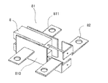
- FIG. 3 is an enlarged perspective view of a brush holder of a rotating electrical machine according to Embodiment 1 of the present invention, and a brush, a current-carrying terminal, and a metal member for cooling a brush installed in the brush holder.
- FIG. The holder, (b) shows a brush, an energization terminal, and a brush cooling metal member installed inside the brush holder.
- a brush cooling metal member 81 which is different from the energization terminal 82, is disposed in the brush holding portion 803 of the brush holder 80.
- the metal member 81 for cooling the brush is fixed to the brush holding portion 803 by insert molding or outsert with a brush holder constituent resin.
- the brush cooling metal member 81 is installed so that at least a part thereof is exposed to the outside of both sides of the brush holding portion 803 in the brush holder 80. Thereby, the heat generated at the brush 8 or the contact portion between the brush 8 and the slip ring 4 is transmitted to the brush cooling metal member 81 and released to the outside of the brush holder 80. Further, since the brush cooling metal member 81 is insert-molded or outsert in the brush holder 80, the installation cost can be reduced as compared with the case where it is separately installed.
- a brush cooling metal member 81 is disposed inside the brush holder constituting resin so as to surround both sides of the brush 8.
- the metal member 81 for cooling the brush includes a first metal member 810 that covers the peripheral surface of the brush 8 and a second metal member that is coupled to the surface of the first metal member 810 and protrudes from the surface in a substantially perpendicular direction. 811.
- the first metal member 810 is insert-molded or outsert in the resin constituting the brush holder 80.
- the brush cooling metal member 81 is installed so as to be insulated from the brush 8.
- a first gold member 810 is provided along the surface of the brush 8 via a resin layer of about 0.5 [mm], and the second metal member 810 is provided with a second By fixing the metal member 811, the brush cooling metal member 81 and the brush 8 can be configured not to contact each other directly.
- the first metal member 810 arranged in parallel with the space in which the brush 8 is accommodated has a larger area from the brush cooling metal member 81 including the first metal member 810 and the second metal member 811.
- the heat dissipation can be improved.
- the first metal member 810 is bent along the space in which the brush 8 is accommodated, and preferably the four surfaces of the brush 8 are surrounded. Can be maximized.
- the mechanical strength of the entire brush holder 80 is improved, and the load from the outside is increased. And can be prevented from being destroyed when subjected to an impact.
- the resin constituting the brush holder 80 is used for insulation between the brush 8 and the brush cooling metal member 81.
- the brush cooling metal member 81 is thermally sprayed.
- an insulating material may be coated with a laminate or the like.
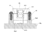
- FIG. 4 is a schematic view showing a cross section including the connection surface between the brush holder and the heat sink in the first embodiment of the rotating electrical machine according to the first embodiment of the present invention.
- the brush holder 80 shown in FIG. 4 corresponds to the AA cross section in FIG.
- the first metal member 810 of the brush cooling metal member 81 has a substantially E-shaped cross-sectional shape so as to surround the half circumferential surfaces of the pair of brushes 8.
- the first metal member 810 of the member 81 is disposed so as to surround substantially the entire circumferential surface of each brush 8.
- the boss portion of the second metal member 811 which is a part of the brush cooling metal member 81 exposed from the brush holder 80 is screwed to the boss portion provided on the fin 30g2 of the heat sink 30g on which the power circuit is mounted. It is connected by.
- the second metal member 811 exposed from the brush holder 80 may be fixed to the heat sink 30g with an adhesive or caulking instead of being fixed to the heat sink 30g with a screw 83.
- the heat sink 30g is a power circuit cooling heat sink, and is designed so that cooling air generated by the rotation of the rotor is efficiently supplied to the fin 30g2 protruding from the base surface 30g1.
- the heat sink 30g has a lower operating temperature than the bracket or the like due to the action of cooling air.
- the brush cooling metal member 81 exposed from the brush holder 80 releases heat generated at the brush 8 or the contact portion between the brush 8 and the slip ring 4 to the connected heat sink 30g by heat conduction. For these reasons, heat is efficiently radiated from the brush 8, and the temperature of the brush 8 is reduced.
- This heat dissipation model is superior in brush cooling performance to a model in which heat generated in the vicinity of the brush 8 is discharged to the outside atmosphere by attaching a heat sink 30g for cooling to the outer periphery of the brush holder 80, for example.
- the exposed portion of the brush cooling metal member 81 is a portion through which a large amount of cooling air flows, and heat radiation can also be expected from the exposed surface of the brush cooling metal member 81.
- the connecting portion of the brush cooling metal member 81 to the heat sink 30g also has a structure for fixing the brush holder. Thereby, it is not necessary to newly provide a structure for fixing the brush holder, and the material and manufacturing cost of the brush holder are reduced. Further, when the brush holder 80 has a separate fixing structure, combined with the brush holder fixing structure in the brush cooling metal member 81, the brush holder fixing strength is further increased.
- the brush cooling metal member 81 When the brush cooling metal member 81 is used for fixing the brush holder 80, compared to the case where the brush holder constituent resin or the like is used for fixing, there is a problem due to resin withering that is a shape change due to a temperature cycle or deterioration over time, Can be prevented. Further, by fixing the brush cooling metal member 81 and the heat sink 30g with screws, an adhesive or caulking, the contact portion between the brush cooling metal member 81 and the heat sink 30g is pressurized or has a thermal conductivity. The contact thermal resistance can be reduced by, for example, filling with a small member. Thereby, the thermal resistance of the heat dissipation path by the metal member 81 for cooling the brush is reduced, and the temperature of the brush can be reduced more efficiently.
- the brush holder 80 according to the first embodiment has a boss portion fixed in addition to the original fixing mechanism, so that the resonance frequency can be set higher than that of the brush holder held only by the normal fixing mechanism. it can.
- the brush holder according to the first embodiment can increase the reliability against vibration.
- FIG. FIG. 5 is a schematic view showing a cross section including a connection surface between a brush holder and a heat sink in a rotary electric machine according to Embodiment 2 of the present invention.
- the first metal member 810 of the brush cooling metal member 81 exposed from the brush holder 80 extends toward the base surface 30g1 side of the heat sink 30g, and its end 8101 faces the base surface 30g1 of the heat sink 30g.
- the boss portion is formed by being bent.
- the end portion 8101 of the first metal member 810 is in contact with and connected to the base surface 30g1 of the heat sink 30g.
- the contact portion between the brush cooling metal member 81 and the heat sink 30g can have a large contact area. For this reason, the contact thermal resistance of this connection part can be made low, and it becomes advantageous at the point which thermally radiates the heat
- FIG. the number of heat dissipation paths to the heat sink 30g also increases at the same time, and heat dissipation is advantageous.
- the brush holder 80 since the brush holder 80 has the boss portion of the first metal member 810 of the brush cooling metal member 81 fixed to the base surface 30g1 of the tote sink 30g, the fixing strength and the vibration suppressing effect are expressed. It is possible to reduce the failure or vibration of the brush holder 80.
- the brush holder 80 is added with fixing of the boss portion and fixing of the heat sink base surface, and the resonance frequency can be set higher than that of the brush holder held only by the normal fixing mechanism.
- the brush holder can increase the reliability against vibration.
- FIG. 6 is a schematic view showing a cross section including a connection surface between the brush holder and the heat sink in the rotary electric machine according to Embodiment 3 of the present invention.
- the first metal member 810 of the brush cooling metal member 81 exposed from the brush holder 80 extends to the base surface 30g1 side of the heat sink 30g, and its end 8101 faces the base surface 30g1 of the heat sink 30g.
- the boss portion is formed by being bent.
- the end portion 8101 of the first metal member 810 is in contact with and connected to the base surface 30g1 of the heat sink 30g.
- the end portion 8101 of the first metal member 810 and the second metal member 811 in the brush cooling metal member 81 are interposed via a high heat dissipation gap filler 900 such as resin, grease or adhesive.
- the heat sink 30g is connected to the base surface 30g1 and the fins 30g2.
- the installation of these high heat dissipation gap fillers 900 also has an effect of preventing foreign matter from entering between the brush cooling metal member 81 of the brush holder 80 and the heat sink 30g.
- FIGS. 7A and 7B are perspective views of a brush holder after resin molding of a rotating electrical machine according to Embodiment 4 of the present invention, where FIG. 7A is a brush holder, and FIG. 7B is a brush installed in the brush holder and for energization.
- the terminal and the metal member for brush cooling are shown.
- the brush cooling metal member 81 includes a first metal member 810 disposed along the peripheral surface of the brush 8, and the first metal member 810.
- a second metal member 811 extending in a right angle direction from the surface and a plurality of third metal members 812 extending in a right angle direction from the surface of the first metal member 810 and bent substantially at a right angle in the middle.
- the first metal member 810 is inserted into the resin constituting the brush holder 80, and the second metal member 811 and the third metal member 812 are exposed to the outside from the resin of the brush holder.
- the third metal member 812 is a heat radiating portion having a heat radiating fin shape or a comb-like shape.
- the second metal member 811 and the third metal member 812 of the brush cooling metal member 81 exposed to the outside of the brush holder 80 can further dissipate heat to the outside atmosphere of the brush holder 80. Promoted.
- the heat generated at the contact portion between the brush 8 or the brush 8 and the slip ring 4 is transmitted from the brush holder 80 to the heat sink 30g by the second metal member 811 and by the third metal member 812. Dispersed in the heat radiated to the atmosphere outside the brush holder 80.
- the brush cooling effect of the brush holder 80 is improved and the temperature of the heat sink 81g to which the brush cooling metal member 81 is connected is prevented.
- the heat radiating portion formed by the second metal member 811 and the third metal member 812 of the brush cooling metal member 81 is disposed at a portion where the flow rate of the cooling air is large. For this reason, the cooling air collides with these heat radiating portions and becomes turbulent under an operating condition with a lower flow velocity. Thereby, not only the said thermal radiation part of the brush holder 80 but the heat transfer rate of the surface of the brush holder 80 improves, and a brush cooling effect improves.
- FIG. A brush holder in a rotary electric machine according to Embodiment 5 of the present invention is a resin having a thermal conductivity of 0.8 [W / mK] or more, such as PPS or PBT, that can effectively exhibit a brush temperature reduction effect.
- Consists of a resin based on FIG. 8 is a characteristic diagram showing the relationship between the thermal conductivity of the brush holder of the rotating electrical machine and the temperature rise of the brush according to Embodiment 5 of the present invention, where the vertical axis is the brush temperature [k] and the horizontal axis is the brush holder. The thermal conductivity [W / mk] is shown.
- the temperature of the brush that rises during power generation, regenerative power generation, drive operation, etc. of the vehicle AC generator or motor generator can be reduced by increasing the thermal conductivity of the brush holder. This is because the heat generated near the brush is conducted to the brush cooling metal member 81 shown in the first to fourth embodiments through the brush holder 80 and discharged to the outside of the brush holder 80. This is considered to be because the thermal resistance between 8 and the brush cooling metal member 81 is reduced.
- the heat generated in the vicinity of the brush 8 is dissipated not only from the brush holder 80 side but also through a plurality of heat dissipation paths such as a heat dissipation path via the slip ring 4 and a heat dissipation path via the pigtail of the brush 8.
- the brush holder of the rotating electrical machine according to the fifth embodiment is made of a synthetic resin having a thermal conductivity of 0.8 [W / mK] or more so that the brush temperature reduction effect can be more effectively exhibited.
- the brush holder 80 is formed.
- the thermal conductivity of the brush holder 80 is desirably set to 0.8 to 3.0 [W / mK].
- the constituent resin of the brush holder 80 and the metal member 81 for cooling the brush are integrated by insert molding or outsert.
- the constituent of the brush holder 80 is configured. Since the resin and the metal member 81 for cooling the brush have different linear expansion coefficients, distortion due to thermal change occurs in the vicinity of the interface boundary.
- the atmosphere in which the AC generator or motor generator for a vehicle is placed has a large temperature difference depending on the use state and the ambient ambient temperature. For this reason, the brush holder requires countermeasures against cracks in the constituent resin for the temperature cycle.
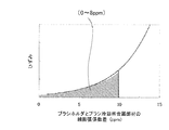
- FIG. 9 shows the relationship between the linear expansion coefficient difference between the constituent resin of the brush holder of the rotating electrical machine and the brush cooling metal member according to Embodiment 5 of the present invention, and the amount of strain generated in the constituent resin of the brush holder when the temperature cycle is added.
- FIG. 9 when the difference in linear expansion coefficient between the constituent resin of the brush holder 80 and the metal member 81 for brush cooling exceeds 10 [ppm], the strain generated in the vicinity of the interface boundary generated by the temperature cycle is increased. The inventors have confirmed that cracks are generated by repeated occurrence. For this reason, in the brush holder of the rotating electrical machine according to the present invention, the difference in linear expansion coefficient between the constituent resin of the brush holder 80 and the metal member 81 for brush cooling is set to 10 [ppm] or less.
- the brush cooling metal member 81 is made of copper (including phosphor bronze) or brass.
- the brush cooling metal member 81 is made of these materials, and the heat transferred from the brush holder 80 is thermally conducted to the heat sink 30g through the brush cooling metal member 81 composed of these members having high thermal conductivity.
- the high brush temperature reduction effect generate
- the brush cooling metal member 81 is made of copper or brass as described above, a high brush temperature reduction effect can be maintained, but when the brush cooling metal member 81 is made of a metal having low thermal conductivity, the same brush cooling performance is achieved. In order for the brush holder 80 to hold, it is necessary to bond heat radiating fins to the outside or to install a large amount of the brush cooling metal member 81.
- the brush holder 80 itself can be reduced in weight by making the brush cooling metal member 81 copper or brass. As a result, the vehicle alternator or the entire motor generator can also be lightened.
- the constituent resin of the brush holder 80 is made of PPS or a resin based on PBT. Thereby, the linear expansion coefficient difference between the brush cooling metal member 81 and the constituent resin of the brush holder 80 can be reduced.
- the brush holder 80 having high heat resistance and mechanical strength of the constituent resin itself of the brush holder 80 can be configured.
- PPS or PBT has high recyclability and is excellent in terms of environment and cost.
- FIG. 10 is a schematic view showing a cross section including a connection surface between a brush holder and a heat sink of a rotary electric machine according to Embodiment 6 of the present invention.
- the brush 8 and the brush cooling metal member 81 are insulated by the constituent resin of the brush holder 80. That is, at least the brush-side surface of the flat plate-like first metal member 810 in the brush cooling metal member 81 faces the brush 8 through the constituent resin of the brush holder 80, and the brush 8 and the brush cooling metal The first metal member 810 of the member 81 is not in direct contact.
- the thickness of the constituent member of the brush holder 80 interposed between the first metal member 810 and the brush 8 of the brush cooling metal member 81 is desirably thin as long as the forming property or strength permits.
- FIG. 11 is a schematic view showing a cross section including a connection surface between a brush holder and a heat sink of a rotary electric machine according to Embodiment 7 of the present invention.
- the insulation between the brush 8 and the brush cooling metal member 81 is configured by a member 910 that has a higher thermal conductivity than the constituent resin of the brush holder 80 or can be configured with a thinner thickness.
- An insulating material having a high thermal conductivity for example, a resin sheet 910 blended with a high thermal conductivity filler is attached to the brush-side surface of the first metal member 810 in the brush cooling metal member 81, or adhered by spraying or laminating. Arranged insulating material.
- the insulation between the brush 8 and the brush cooling metal member 81 is ensured by the insulating material 910 having a high thermal conductivity and / or a reduced thickness.
- the thermal resistance between the metal members 81 can be greatly reduced.
- most of the heat generated in the vicinity of the brush is drawn to the heat dissipation path passing through the brush cooling metal member 81 and is thermally conducted to the heat sink 30g having a low temperature, thereby obtaining a high brush temperature rise suppressing effect.
- the brush 8 and the brush cooling metal member 91 are arranged via the thin insulating material, the necessary volume of the brush holder 80 itself is reduced, and the amount of molding resin used is reduced, and the brush holder 80 is also reduced. Weight can also be reduced. As a result, the vehicle AC generator or motor generator can be reduced in weight.
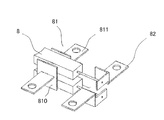
- FIG. FIG. 12 is a perspective view of a brush, a metal member for cooling a brush, and a terminal for energization that are included in a resin for constituting a brush holder of a rotating electrical machine according to Embodiment 8 of the present invention.
- the brush cooling metal member 81 is composed of two first metal members 810 and two second metal members 811, and 2 so as to correspond to almost the entire side surface of the brush 8.
- the surfaces of the two first metal members 810 are formed as large as possible, and the surfaces of the two first metal members 810 are arranged so as to face each other via the brush 8.
- the brush cooling metal member 81 may be disposed so as to surround the brush 8. The area where the brush cooling metal member 81 receives heat from the brush 8 is further increased, and the structure of the brush holder serves as a framework to improve the structural strength.
- FIG. FIG. 13 is a perspective view of a brush, a brush cooling metal member, and a current-carrying terminal included in a resin for constituting a brush holder of a rotating electrical machine according to Embodiment 9 of the present invention.
- the first metal member 810 in the brush cooling metal member 81 is disposed near the contact portion between the slip ring 4 (not shown) and the brush 8.
- the second metal member 810 of the brush cooling metal member 81 as close as possible to the contact portion between the slip ring 4 and the brush 8, the brush cooling effect can be increased. Further, even when the surface of the first metal member facing the brush 8 cannot be made large in the length direction of the brush 8 as shown in FIG. The effect can be maintained.
- FIG. FIG. 14 is a perspective view of a brush holder for a rotating electrical machine according to Embodiment 10 of the present invention.
- the second metal member 811 of the brush cooling metal member 81 includes a plurality of first members 811a extending substantially vertically from the side surface of the brush holder 80 and second members 811b extending substantially perpendicularly from the first member 811a. It consists of connecting parts. Thereby, the freedom degree of design at the time of shape
- the brush cooling metal member 81 is preferably in a position that does not hinder the flow of cooling air caused by the fan installed in the rotor.
- FIG. FIG. 15 is a perspective view of a brush holder for a rotating electrical machine according to Embodiment 11 of the present invention.
- the brush holder 80 includes a metal plate 920 for heat diffusion attached to the wall surface of the space portion of the brush holding portion 803 that stores the brush 8.
- the brush cooling metal member 81 is composed of a first metal member 810 and a second metal member 811 which are embedded in the constituent resin of the brush holder 80 and face each other via the book constituent resin of the brush holder.
- the metal plate 920 for heat diffusion is made of copper, aluminum or iron. According to the eleventh embodiment, the heat generated in the vicinity of the brush is diffused in the direction of the plane of the first metal member 810 of the brush cooling metal member 81 by the metal plate 920 for heat diffusion, and the heat conduction area. By taking a large value, the thermal resistance of this path can be reduced. As a result, a brush holder having a high brush cooling property can be configured.
- FIG. FIG. 16 is a schematic view showing a cross section including a connection surface between a brush holder and a heat sink of a rotary electric machine according to Embodiment 12 of the present invention.
- the brush cooling metal member 81 is fixed to the first metal member 810 fixed to the outer surface of the brush holder 80 after the resin molding of the brush holder 80 and the first metal member 801.
- the second metal member 811 is used.
- the degree of freedom of shape of the brush cooling metal member 81 that can be installed can be improved.
- the metal member for brush cooling can be arrange
- FIG. As a result, it is possible to avoid reducing the flow rate of the cooling air blown to the brush 8 and the heat sink 30g, and to reduce the temperature rise of the brush 8 and the heat sink 30g.
- the brush cooling metal member 81 attached to the outer peripheral surface of the brush holder 80 is a method that can reduce the thermal resistance of the contact portion between the brush holder 80 and the brush cooling metal member 81 as much as possible, such as fixing with a high thermal conductive adhesive or screw. It is good to fix. Thereby, the thermal resistance of this heat radiation path can be reduced, and the brush temperature reduction effect can be improved.
- the present invention can be used in the field of the automobile industry, particularly in the field of rotating electrical machines mounted on automobiles.
Landscapes
- Engineering & Computer Science (AREA)
- Power Engineering (AREA)
- Motor Or Generator Cooling System (AREA)
- Motor Or Generator Current Collectors (AREA)
- Motor Or Generator Frames (AREA)
Abstract
Description
以下、この発明の実施の形態1による回転電機について図に基づいて説明する。図1は、この発明の実施の形態1による回転電機の断面図である。この実施の形態1による回転電機は、車両用の交流発電電動機(モータジェネレータ)を示しているが、車両用の交流発電機でも適用可能である。
図5は、この発明の実施の形態2による回転電機における、ブラシホルダとヒートシンクとの接続面を含む断面を示す概略図である。図5において、ブラシホルダ80から露出したブラシ冷却用金属部材81の第1の金属部材810は、ヒートシンク30gのベース面30g1側に延び、その端部8101がヒートシンク30gのベース面30g1に対向するように折り曲げられてボス部を形成している。この第1の金属部材810の端部8101は、ヒートシンク30gのベース面30g1に当接して接続されている。
実施の形態4.
この発明の実施の形態5による回転電機におけるブラシホルダは、ブラシ温度低減効果を効果的に発現することができる熱伝導率が0.8[W/mK]以上の樹脂、例えばPPS、もしくは、PBTをベースにした樹脂により構成される。図8は、この発明の実施の形態5による回転電機のブラシホルダの熱伝導率とブラシの温度上昇の関係を示す特性図であり、縦軸はブラシの温度[k]、横軸はブラシホルダの熱伝導率[W/mk]を示す。
図10は、この発明の実施の形態6による回転電機のブラシホルダとヒートシンクとの接続面を含む断面を示す概略図である。図10において、ブラシ8とブラシ冷却用金属部材81とは、ブラシホルダ80の構成樹脂により絶縁される構成となっている。即ち、少なくともブラシ冷却用金属部材81における平板状の第1の金属部材810のブラシ側の面は、ブラシホルダ80の構成樹脂を介してブラシ8に対向しており、ブラシ8とブラシ冷却用金属部材81の第1の金属部材810とが直接接触することがない。
図11は、この発明の実施の形態7による回転電機のブラシホルダとヒートシンクとの接続面を含む断面を示す概略図である。図11において、ブラシ8とブラシ冷却用金属部材81との絶縁は、ブラシホルダ80の構成樹脂よりも熱伝導率が高い、もしくは、薄い厚みで構成できる部材910により構成されている。ブラシ冷却用金属部材81における第1の金属部材810のブラシ側の表面に、熱伝導率が高い絶縁材料、たとえば、高熱伝導フィラーを配合した樹脂シート910を貼り付けたり、溶射やラミネートなどで付着させた絶縁材料を配置する。
図12は、この発明の実施の形態8による回転電機のブラシホルダ構成樹脂に包括されるブラシとブラシ冷却用金属部材と通電用ターミナルの斜視図である。図12に示すように、ブラシ冷却用金属部材81は、2つの第1の金属部材810と、2つの第2の金属部材811により構成し、ブラシ8の側面のほぼ全域に対応するように2つの第1の金属部材810の表面を可能な限り大きく形成し、この2つの第1の金属部材810の表面を、ブラシ8を介して互いに向かい合うように配置している。
図13は、この発明の実施の形態9による回転電機のブラシホルダ構成樹脂に包括されるブラシとブラシ冷却用金属部材と通電用ターミナルの斜視図である。図13に示すように、ブラシ冷却用金属部材81における第1の金属部材810は、スリップリング4(図示せず)とブラシ8の接触部付近に配置されている。このように、出来るだけスリップリング4とブラシ8との接触部の近傍に、ブラシ冷却用金属部材81の第2の金属部材810を配置することで、ブラシ冷却効果を大きくとることができる。また、ブラシホルダ80の形状の制約などで前述の図12のようにブラシ8と対向する第1の金属部材の表面をブラシ8の長さ方向に大きくとれないような場合などでも、ブラシ温度低減効果を保持できる。
図14は、この発明の実施の形態10による回転電機のブラシホルダの斜視図である。ブラシ冷却用金属部材81の第2の金属部材811は、ブラシホルダ80の側面からほぼ垂直に延びる第1部材811aとこの第1部材811aからほぼ直角方向に延びる第2部材811bとの複数個のパーツを接続することで構成されている。これにより、ブラシホルダ80を成形する際の、設計の自由度を高くすることができる。ブラシ冷却用金属部材81は、回転子に設置されたファンにより引き起こされる冷却風の流れを妨げない位置にすることが望ましい。
図15は、この発明の実施の形態11による回転電機のブラシホルダの斜視図である。図15に示すように、ブラシホルダ80は、ブラシ8を格納するブラシ保持部803の空間部の壁面に装着された熱拡散用の金属性プレート920を備えている。ブラシ冷却用金属部材81は、ブラシホルダ80の構成樹脂に埋設されブラシホルダの簿構成樹脂を介して対向する第1の金属部材810と、第2の金属部材811とにより構成される。
図16は、この発明の実施の形態12による回転電機のブラシホルダとヒートシンクとの接続面を含む断面を示す概略図である。図16に示すように、ブラシ冷却用金属部材81は、ブラシホルダ80の樹脂成形後にブラシホルダ80の外側面に固定された第1の金属部材810と、第1の金属部材801に固定された第2の金属部材811とにより構成されている。
4 スリップリング、 5 固定子、 6、7 ハウジング、
8 ブラシ、 9 スリップリングターミナル、 10 回転子、
11 口出し線巻き付け部、 12 冷却用ファン、
13 冷却用ファン、 14 スリップリングモールド部、
15 スプリング、 16 回転センサ、
18 コイル口出し線、 19 ベアリング、 20 プーリ、
30 パワー回路部、 30a パワー素子、 30b パワー素子、
30g ヒートシンク、 30g1 ヒートシンクのベース面、
30g2 フィン、 31 界磁回路部、 32 制御回路部、
32a 制御回路基板、 33a 防水カバー、
35 外部用接続コネクタ、 40 露出部、 50 モールド樹脂、
60 モールド成形品、 80 ブラシホルダ、
81 ブラシ冷却用金属部材、 810 第1の金属部材、
811 第2の金属部材、82 通電用ターミナル、 83 ねじ、
900 高放熱隙間充填材、 812 第3の金属部材
910 樹脂シート、 920 金属プレート
Claims (20)
- 回転軸に固定された界磁鉄心と界磁巻線を有する回転子と、
前記回転軸に固定され、前記界磁巻線に界磁電流を供給するスリップリングと、
前記回転子の外周面に間隙を介して配置され、電機子巻線を有する固定子と、
前記固定子を固定するハウジングと、
前記ハウジングに固定され、前記スリップリングを介して上記界磁巻線に界磁電流を供給するブラシを保持するブラシホルダと、
前記ハウジングに固定され、前記界磁電流を制御する界磁回路と前記電機子巻線に流れる電機子電流を制御するパワー回路を搭載したヒートシンクと、
を備えた回転電機であって、
前記ブラシホルダは、前記界磁回路と前記ブラシとを電気的に接続する通電用ターミナルと、前記ブラシを冷却するブラシ冷却用金属部材とを備えている、
ことを特徴とする回転電機。 - 前記ブラシ冷却用金属部材は、前記ブラシに対して電気的に絶縁されている、
ことを特徴とする請求項1に記載の回転電機。 - 前記ブラシ冷却用金属部材は、前記ブラシホルダにインサート成形されている、
ことを特徴とする請求項1又は2に記載の回転電機。 - 前記ブラシ冷却用金属部材は、すくなくとも一部分が前記ブラシホルダの外部に露出した露出部を備えている、
ことを特徴とする請求項1乃至3のうちの何れか一項に記載の回転電機。 - 前記ブラシ冷却用金属部材の前記露出部は、その少なくとも一部が前記ヒートシンクに接続されている、
ことを特徴とする請求項4に記載の回転電機。 - 前記ブラシ冷却用金属部材の前記露出部は、前記ブラシホルダを直接又は間接的に前記ハウジングに固定するための構造を備える、
ことを特徴とする請求項4又は5に記載の回転電機。 - 前記ヒートシンクは、ブラシホルダ固定用のボス部を備え、
前記ブラシ冷却用金属部材の前記露出部は、前記ヒートシンクのボス部に固定される、
ことを特徴とする請求項4乃至6のうちの何れか一項に記載の回転電機。 - 前記ブラシ冷却用金属部材の前記露出部は、前記ヒートシンクのベース面に固定されている、
ことを特徴とする請求項4乃至7のうちの何れか一項に記載の回転電機。 - 前記ブラシ冷却用金属部材と前記ヒートシンクとは、熱伝導率の高い樹脂、グリース、接着材のうちの少なくとも一つを介して接続されている、
ことを特徴とする請求項5乃至8のうちの何れか一項に記載の回転電機。 - 前記ブラシ冷却用金属部材の前記露出部は、少なくとも一部が折曲したフィン状もしくはくし歯状に形成されている、
ことを特徴とする請求項4乃至9のうちの何れか一項に記載の回転電機。 - 前記ブラシホルダは、熱伝導率が0.8[W/mK]以上の材料で構成されている、
ことを特徴とした請求項1乃至10のうちの何れか一項に記載の回転電機。 - 前記ブラシホルダを構成する材料と前記ブラシ冷却用金属部材の材質との線膨張係数差が10[ppm]以内である、
ことを特徴とする請求項1乃至11のうちの何れか一項に記載の回転電機。 - 前記ブラシホルダを構成する材料は、PPSもしくはPBTであり、
前記ブラシ冷却用金属部材を構成する材料は、銅もしくは真鍮である、
ことを特徴とする請求項1乃至12のうちの何れか一項に記載の回転電機。 - 前記ブラシと前記ブラシ冷却用金属部材との間に、前記ブラシホルダを構成する樹脂が配置されている、
ことを特徴とする請求項1乃至13のうちの何れか一項に記載の回転電機。 - 前記ブラシと前記ブラシ冷却用金属部材との間に、前記ブラシホルダを構成する樹脂よりも熱伝導率の高い部材が配置されている、
ことを特徴とする請求項1乃至13のうちの何れか一項に記載の回転電機。 - 前記ブラシ冷却用金属部材は、前記ブラシの少なくとも外周面の周面の一部に対向して配置されている、
ことを特徴とする請求項1乃至15のうちの何れか一項に記載の回転電機。 - 前記ブラシ冷却用金属部材は、少なくとも前記スリップリングと前記ブラシとの接触部近傍に配置されている、
ことを特徴とする請求項1乃至16のうちの何れか一項に記載の回転電機。 - 前記ブラシ冷却用金属部材は、複数個の部材により構成されている、
ことを特徴とする請求項1乃至17のうちの何れか一項に記載の回転電機。 - 前記ブラシホルダは、前記ブラシが格納される空間部の壁面に熱拡散用のプレートを備え
前記ブラシ冷却用金属部材は、その一部が前記プレートに並行して配置されている、
ことを特徴とする請求項1乃至18のうちの何れか一項に記載の回転電機。 - 前記ブラシ冷却用金属部材は、前記ブラシホルダの成形後に前記ブラシホルダ外側面に固定される、
ことを特徴とする請求項1乃至3、9、11乃至19のうちの何れか一項に記載の回転電機。
Priority Applications (5)
| Application Number | Priority Date | Filing Date | Title |
|---|---|---|---|
| PCT/JP2011/063027 WO2012169007A1 (ja) | 2011-06-07 | 2011-06-07 | 回転電機 |
| EP11867230.2A EP2688185B1 (en) | 2011-06-07 | 2011-06-07 | Rotating electrical machine |
| JP2013519258A JP5649728B2 (ja) | 2011-06-07 | 2011-06-07 | 回転電機 |
| CN201180069822.XA CN103460568B (zh) | 2011-06-07 | 2011-06-07 | 旋转电机 |
| US14/004,198 US9479029B2 (en) | 2011-06-07 | 2011-06-07 | Electric rotating machine |
Applications Claiming Priority (1)
| Application Number | Priority Date | Filing Date | Title |
|---|---|---|---|
| PCT/JP2011/063027 WO2012169007A1 (ja) | 2011-06-07 | 2011-06-07 | 回転電機 |
Publications (1)
| Publication Number | Publication Date |
|---|---|
| WO2012169007A1 true WO2012169007A1 (ja) | 2012-12-13 |
Family
ID=47295614
Family Applications (1)
| Application Number | Title | Priority Date | Filing Date |
|---|---|---|---|
| PCT/JP2011/063027 Ceased WO2012169007A1 (ja) | 2011-06-07 | 2011-06-07 | 回転電機 |
Country Status (5)
| Country | Link |
|---|---|
| US (1) | US9479029B2 (ja) |
| EP (1) | EP2688185B1 (ja) |
| JP (1) | JP5649728B2 (ja) |
| CN (1) | CN103460568B (ja) |
| WO (1) | WO2012169007A1 (ja) |
Cited By (3)
| Publication number | Priority date | Publication date | Assignee | Title |
|---|---|---|---|---|
| JP2016226231A (ja) * | 2015-06-03 | 2016-12-28 | 株式会社デンソー | 回転電機 |
| JP6067087B1 (ja) * | 2015-11-06 | 2017-01-25 | 三菱電機株式会社 | 車両用回転電機 |
| JP2020078226A (ja) * | 2018-09-27 | 2020-05-21 | ロベルト・ボッシュ・ゲゼルシャフト・ミト・ベシュレンクテル・ハフツングRobert Bosch Gmbh | 駆動装置、液圧ポンプ、自動車 |
Families Citing this family (9)
| Publication number | Priority date | Publication date | Assignee | Title |
|---|---|---|---|---|
| CN103609007A (zh) * | 2011-07-28 | 2014-02-26 | 三菱电机株式会社 | 旋转电机 |
| JP6453658B2 (ja) * | 2015-01-21 | 2019-01-16 | 株式会社マキタ | 電動工具 |
| KR102596664B1 (ko) * | 2016-07-18 | 2023-11-02 | 엘지이노텍 주식회사 | 모터 |
| FR3064133B1 (fr) * | 2017-03-15 | 2022-07-08 | Valeo Equip Electr Moteur | Porte-balai pour machine electrique tournante |
| FR3067884B1 (fr) * | 2017-06-20 | 2019-07-05 | Valeo Equipements Electriques Moteur | Porte-balai pour machine electrique tournante |
| CN109086130B (zh) * | 2018-06-06 | 2022-06-10 | 北京嘉楠捷思信息技术有限公司 | 计算设备的芯片调频方法、装置、算力板、计算设备及存储介质 |
| US12287717B2 (en) | 2018-06-06 | 2025-04-29 | Canaan Creative Co., Ltd. | Chip frequency modulation method and apparatus of computing device, hash board, computing device and storage medium |
| EP3745544A1 (de) * | 2019-05-28 | 2020-12-02 | Siemens Aktiengesellschaft | Schleifringsystem mit verbesserter kühlung |
| FR3155665A1 (fr) * | 2023-11-22 | 2025-05-23 | Ampere | Machine électrique à excitation électrique munie d’un dispositif de refroidissement |
Citations (6)
| Publication number | Priority date | Publication date | Assignee | Title |
|---|---|---|---|---|
| JPH05199701A (ja) * | 1991-11-06 | 1993-08-06 | Nippondenso Co Ltd | 防爆型回転電機 |
| JP2002240771A (ja) * | 2001-02-14 | 2002-08-28 | Yamaha Motor Co Ltd | 電動補助自転車用電動ユニット |
| JP2003047207A (ja) | 2001-07-31 | 2003-02-14 | Asmo Co Ltd | モータ |
| JP2008236979A (ja) | 2007-03-23 | 2008-10-02 | Mitsubishi Electric Corp | 電動パワーステアリング装置用モータおよびその製造方法 |
| JP2009177993A (ja) | 2008-01-28 | 2009-08-06 | Denso Corp | 車両用交流発電機 |
| JP2010268541A (ja) * | 2009-05-12 | 2010-11-25 | Mitsubishi Electric Corp | 回転電機 |
Family Cites Families (8)
| Publication number | Priority date | Publication date | Assignee | Title |
|---|---|---|---|---|
| US4859894A (en) * | 1986-09-01 | 1989-08-22 | Mitsuba Electric Mfg. Co., Ltd. | Alternating current generator for use in a vehicle |
| US4959576A (en) * | 1987-11-25 | 1990-09-25 | Nippondenso Co., Ltd. | Automotive alternator |
| FR2764132B1 (fr) * | 1997-05-30 | 1999-08-20 | Valeo Systemes Dessuyage | Cage pour balai de moteur electrique a ailettes de refroidissement |
| US5949175A (en) * | 1998-02-05 | 1999-09-07 | Rexair, Inc. | Brush holder for electric motor |
| US6664699B2 (en) * | 2000-08-11 | 2003-12-16 | Denso Corporation | Rotary electric machine |
| US20030111929A1 (en) * | 2001-12-13 | 2003-06-19 | Valeo Electrical Systems, Inc. | Metal brush box with heat sink fins for decreasing brush temperature in an electric motor or alternator |
| JP3661655B2 (ja) * | 2002-02-27 | 2005-06-15 | 株式会社デンソー | 回転電機のブラシ組体の組付けに用いるブラシサポート治具及びそれを用いたブラシ組体の組付け方法 |
| FR2967842B1 (fr) * | 2010-11-22 | 2012-11-30 | Valeo Equip Electr Moteur | Ensemble monobloc regulateur de tension - porte-balais de machine electrique tournante et machine electrique tournante comprenant un tel ensemble |
-
2011
- 2011-06-07 JP JP2013519258A patent/JP5649728B2/ja active Active
- 2011-06-07 EP EP11867230.2A patent/EP2688185B1/en active Active
- 2011-06-07 US US14/004,198 patent/US9479029B2/en not_active Expired - Fee Related
- 2011-06-07 WO PCT/JP2011/063027 patent/WO2012169007A1/ja not_active Ceased
- 2011-06-07 CN CN201180069822.XA patent/CN103460568B/zh active Active
Patent Citations (6)
| Publication number | Priority date | Publication date | Assignee | Title |
|---|---|---|---|---|
| JPH05199701A (ja) * | 1991-11-06 | 1993-08-06 | Nippondenso Co Ltd | 防爆型回転電機 |
| JP2002240771A (ja) * | 2001-02-14 | 2002-08-28 | Yamaha Motor Co Ltd | 電動補助自転車用電動ユニット |
| JP2003047207A (ja) | 2001-07-31 | 2003-02-14 | Asmo Co Ltd | モータ |
| JP2008236979A (ja) | 2007-03-23 | 2008-10-02 | Mitsubishi Electric Corp | 電動パワーステアリング装置用モータおよびその製造方法 |
| JP2009177993A (ja) | 2008-01-28 | 2009-08-06 | Denso Corp | 車両用交流発電機 |
| JP2010268541A (ja) * | 2009-05-12 | 2010-11-25 | Mitsubishi Electric Corp | 回転電機 |
Cited By (5)
| Publication number | Priority date | Publication date | Assignee | Title |
|---|---|---|---|---|
| JP2016226231A (ja) * | 2015-06-03 | 2016-12-28 | 株式会社デンソー | 回転電機 |
| US10320267B2 (en) | 2015-06-03 | 2019-06-11 | Denso Corporation | Rotary electric machine |
| JP6067087B1 (ja) * | 2015-11-06 | 2017-01-25 | 三菱電機株式会社 | 車両用回転電機 |
| JP2020078226A (ja) * | 2018-09-27 | 2020-05-21 | ロベルト・ボッシュ・ゲゼルシャフト・ミト・ベシュレンクテル・ハフツングRobert Bosch Gmbh | 駆動装置、液圧ポンプ、自動車 |
| JP7465070B2 (ja) | 2018-09-27 | 2024-04-10 | ロベルト・ボッシュ・ゲゼルシャフト・ミト・ベシュレンクテル・ハフツング | 駆動装置、液圧ポンプ、自動車 |
Also Published As
| Publication number | Publication date |
|---|---|
| US9479029B2 (en) | 2016-10-25 |
| US20140001915A1 (en) | 2014-01-02 |
| EP2688185B1 (en) | 2018-01-17 |
| EP2688185A4 (en) | 2015-12-09 |
| EP2688185A1 (en) | 2014-01-22 |
| CN103460568A (zh) | 2013-12-18 |
| CN103460568B (zh) | 2016-01-27 |
| JPWO2012169007A1 (ja) | 2015-02-23 |
| JP5649728B2 (ja) | 2015-01-07 |
Similar Documents
| Publication | Publication Date | Title |
|---|---|---|
| JP5649728B2 (ja) | 回転電機 | |
| CN103548246B (zh) | 驱动装置一体型旋转电机 | |
| JP6621491B2 (ja) | 回転電機 | |
| JP5893099B1 (ja) | 電力供給ユニット一体型回転電機 | |
| JP2015122856A (ja) | 回転電機一体型制御装置 | |
| WO2013069104A1 (ja) | 回転電機 | |
| JP5638701B2 (ja) | 回転電機 | |
| US9653969B2 (en) | Brush structure with heat dissipation member | |
| JP6207650B2 (ja) | 回転電機 | |
| JP5602786B2 (ja) | 回転電機 | |
| JP4675268B2 (ja) | モールド電動機及び空気調和機 | |
| EP3826148B1 (en) | Rotating electric machine | |
| JP5323034B2 (ja) | 回転電機 | |
| JP2010074990A (ja) | ポンプ用dcモータの放熱構造 | |
| JP2011166977A (ja) | モールドモータ | |
| JP2021118624A (ja) | モータ | |
| JPWO2013014783A1 (ja) | 回転電機 | |
| JP2013106361A (ja) | 制御装置一体型回転電機 | |
| JPH06510897A (ja) | 電気機械用冷却装置 | |
| JP2023104510A (ja) | 電制スロットル装置 | |
| JPH04111258U (ja) | 電動機 |
Legal Events
| Date | Code | Title | Description |
|---|---|---|---|
| 121 | Ep: the epo has been informed by wipo that ep was designated in this application |
Ref document number: 11867230 Country of ref document: EP Kind code of ref document: A1 |
|
| ENP | Entry into the national phase |
Ref document number: 2013519258 Country of ref document: JP Kind code of ref document: A |
|
| WWE | Wipo information: entry into national phase |
Ref document number: 14004198 Country of ref document: US |
|
| WWE | Wipo information: entry into national phase |
Ref document number: 2011867230 Country of ref document: EP |
|
| NENP | Non-entry into the national phase |
Ref country code: DE |