WO2012169133A1 - 音声符号化装置、音声復号装置、音声符号化方法及び音声復号方法 - Google Patents
音声符号化装置、音声復号装置、音声符号化方法及び音声復号方法 Download PDFInfo
- Publication number
- WO2012169133A1 WO2012169133A1 PCT/JP2012/003409 JP2012003409W WO2012169133A1 WO 2012169133 A1 WO2012169133 A1 WO 2012169133A1 JP 2012003409 W JP2012003409 W JP 2012003409W WO 2012169133 A1 WO2012169133 A1 WO 2012169133A1
- Authority
- WO
- WIPO (PCT)
- Prior art keywords
- band
- signal
- spectrum
- means includes
- input signal
- Prior art date
- Legal status (The legal status is an assumption and is not a legal conclusion. Google has not performed a legal analysis and makes no representation as to the accuracy of the status listed.)
- Ceased
Links
Images








Classifications
-
- H—ELECTRICITY
- H04—ELECTRIC COMMUNICATION TECHNIQUE
- H04B—TRANSMISSION
- H04B1/00—Details of transmission systems, not covered by a single one of groups H04B3/00 - H04B13/00; Details of transmission systems not characterised by the medium used for transmission
- H04B1/66—Details of transmission systems, not covered by a single one of groups H04B3/00 - H04B13/00; Details of transmission systems not characterised by the medium used for transmission for reducing bandwidth of signals; for improving efficiency of transmission
- H04B1/667—Details of transmission systems, not covered by a single one of groups H04B3/00 - H04B13/00; Details of transmission systems not characterised by the medium used for transmission for reducing bandwidth of signals; for improving efficiency of transmission using a division in frequency subbands
-
- G—PHYSICS
- G10—MUSICAL INSTRUMENTS; ACOUSTICS
- G10L—SPEECH ANALYSIS TECHNIQUES OR SPEECH SYNTHESIS; SPEECH RECOGNITION; SPEECH OR VOICE PROCESSING TECHNIQUES; SPEECH OR AUDIO CODING OR DECODING
- G10L19/00—Speech or audio signals analysis-synthesis techniques for redundancy reduction, e.g. in vocoders; Coding or decoding of speech or audio signals, using source filter models or psychoacoustic analysis
- G10L19/02—Speech or audio signals analysis-synthesis techniques for redundancy reduction, e.g. in vocoders; Coding or decoding of speech or audio signals, using source filter models or psychoacoustic analysis using spectral analysis, e.g. transform vocoders or subband vocoders
- G10L19/0204—Speech or audio signals analysis-synthesis techniques for redundancy reduction, e.g. in vocoders; Coding or decoding of speech or audio signals, using source filter models or psychoacoustic analysis using spectral analysis, e.g. transform vocoders or subband vocoders using subband decomposition
-
- G—PHYSICS
- G10—MUSICAL INSTRUMENTS; ACOUSTICS
- G10L—SPEECH ANALYSIS TECHNIQUES OR SPEECH SYNTHESIS; SPEECH RECOGNITION; SPEECH OR VOICE PROCESSING TECHNIQUES; SPEECH OR AUDIO CODING OR DECODING
- G10L19/00—Speech or audio signals analysis-synthesis techniques for redundancy reduction, e.g. in vocoders; Coding or decoding of speech or audio signals, using source filter models or psychoacoustic analysis
- G10L19/04—Speech or audio signals analysis-synthesis techniques for redundancy reduction, e.g. in vocoders; Coding or decoding of speech or audio signals, using source filter models or psychoacoustic analysis using predictive techniques
- G10L19/16—Vocoder architecture
- G10L19/18—Vocoders using multiple modes
- G10L19/24—Variable rate codecs, e.g. for generating different qualities using a scalable representation such as hierarchical encoding or layered encoding
-
- G—PHYSICS
- G10—MUSICAL INSTRUMENTS; ACOUSTICS
- G10L—SPEECH ANALYSIS TECHNIQUES OR SPEECH SYNTHESIS; SPEECH RECOGNITION; SPEECH OR VOICE PROCESSING TECHNIQUES; SPEECH OR AUDIO CODING OR DECODING
- G10L19/00—Speech or audio signals analysis-synthesis techniques for redundancy reduction, e.g. in vocoders; Coding or decoding of speech or audio signals, using source filter models or psychoacoustic analysis
- G10L19/02—Speech or audio signals analysis-synthesis techniques for redundancy reduction, e.g. in vocoders; Coding or decoding of speech or audio signals, using source filter models or psychoacoustic analysis using spectral analysis, e.g. transform vocoders or subband vocoders
-
- G—PHYSICS
- G10—MUSICAL INSTRUMENTS; ACOUSTICS
- G10L—SPEECH ANALYSIS TECHNIQUES OR SPEECH SYNTHESIS; SPEECH RECOGNITION; SPEECH OR VOICE PROCESSING TECHNIQUES; SPEECH OR AUDIO CODING OR DECODING
- G10L21/00—Speech or voice signal processing techniques to produce another audible or non-audible signal, e.g. visual or tactile, in order to modify its quality or its intelligibility
- G10L21/02—Speech enhancement, e.g. noise reduction or echo cancellation
- G10L21/038—Speech enhancement, e.g. noise reduction or echo cancellation using band spreading techniques
Definitions
- the present invention relates to a speech encoding apparatus, a speech decoding apparatus, a speech encoding method, and a speech decoding method having a scalable configuration, for example.
- Mobile communication systems are required to transmit audio signals compressed at a low bit rate in order to effectively use radio resources and the like.
- it is also desired to improve the quality of call voice and to realize a call service with a high sense of reality.
- This technique includes a first layer that encodes an input signal in a wide band (0 kHz to 7 kHz), and a band extension layer that encodes an ultra wide band (7 kHz to 16 kHz) using the input signal and the decoded signal of the first layer.
- a wideband part the signal band (0 kHz to 7 kHz) encoded in the first layer
- the signal band (7 kHz to 16 kHz) encoded in the band extension layer is referred to as an extension band part.
- FIG. 1 is a diagram illustrating a wideband part and an extended band part in an input signal spectrum.
- the technique of performing hierarchical encoding in this way is general because the bitstream obtained from the encoding device has scalability, that is, a decoded signal can be obtained even from partial information of the bitstream. This is called scalable coding (hierarchical coding).
- the scalable coding scheme can be flexibly adapted to communication between networks with different bit rates because of its nature, so it can be said that it is suitable for the future network environment in which various networks are integrated by the IP protocol.
- Non-Patent Document 1 As an example of realizing scalable coding using a technology standardized by ITU-T (International Telecommunication Union Telecommunication Standardization Sector), for example, there is a technology disclosed in Non-Patent Document 1.
- a wideband signal is encoded in the first layer, and in the band extension layer, encoding is performed by extending the signal of the extension band part using the signal of the wideband part.
- the bit rate is high because the signal band is wide and the amount of information is large.
- the bit rate that can be used for voice calls is limited, there is a demand for voice calls with a bit rate as low as possible.
- frequency resources are limited, so it is necessary to suppress the communication capacity of each line, and the total bit rate used by the voice codec must be suppressed to about 16 kbps.
- An object of the present invention is to provide a speech encoding device, speech decoding device, speech encoding method, and speech decoding method that can prevent overall quality degradation associated with encoding even when the bit rate is lowered. is there.
- the speech encoding apparatus of the present invention is a speech encoding apparatus that encodes a wideband signal in a first layer and encodes an extended band signal that is higher than the wideband in the bandwidth extension layer, A configuration is adopted that includes band selection means for selecting a band to be restricted in encoding in the extension band, and band restriction means for applying the restriction to the selected band among the bands of the input signal.
- the speech decoding apparatus decodes, in the first layer, first layer encoded information obtained by encoding a wideband signal generated in the encoding apparatus, and is higher than the wideband.
- the speech coding method of the present invention is a speech coding method for coding a wideband signal in a first layer and coding a signal in an extension band higher than the wideband in the band extension layer.
- the speech decoding method of the present invention is a speech decoding method for decoding a wideband signal in a first layer and decoding a signal in an extension band higher than the wideband in a band extension layer.
- the present invention even when the bit rate is lowered, it is possible to prevent the overall quality deterioration accompanying the encoding.
- Block diagram showing a modification of the speech encoding apparatus according to Embodiment 2 of the present invention The block diagram which shows the structure of the adaptive zone
- voice coding apparatus which is not a scalable structure
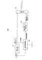
- FIG. 2 is a block diagram showing a configuration of speech encoding apparatus 100 according to Embodiment 1 of the present invention.
- the speech encoding apparatus 100 generates a bit stream by encoding an input signal at predetermined time intervals (frames), and transmits the generated bit stream to a transmission channel (not shown).
- 1st layer encoding part 101 performs the encoding process in the 1st layer of an input signal, and produces
- First layer encoding section 101 outputs the generated first layer encoded data to band extension layer encoding section 103 and multiplexing section 104.
- the adaptive band limiting unit 102 selects a band to be limited based on the pitch period of the input signal, and limits the selected band among the band of the input signal of the band extension layer. Then, adaptive band limiting section 102 outputs a band limited signal obtained by limiting the selected band to band enhancement layer encoding section 103.
- the band to which the restriction is applied is a band excluded from the encoding target in the band extension layer or a band in which energy is attenuated in the band extension layer. Details of the configuration of the adaptive band limiting unit 102 will be described later.
- Band extension layer encoding section 103 uses the first layer encoded data input from first layer encoding section 101 and the band limited signal input from adaptive band limiting section 102 to use the band extension layer of the extension band section. To perform band extension layer encoded data. Band extension layer encoding section 103 outputs the generated band extension layer encoded data to multiplexing section 104.
- the multiplexing unit 104 multiplexes the first layer encoded data input from the first layer encoding unit 101 and the band extension layer encoded data input from the band extension layer encoding unit 103 to generate a bitstream.
- the generated bit stream is output to a communication channel (not shown).
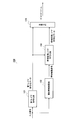
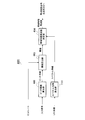
- FIG. 3 is a block diagram showing a configuration of adaptive band limiting section 102 in the present embodiment.
- the adaptive band selection unit 301 analyzes the characteristics of the input signal and selects a band to which a restriction is applied in the input signal based on the analysis result.
- the adaptive band selection unit 301 outputs information on the band to which the selected limitation is applied to the band limitation signal generation unit 302 as a band limitation frequency. Details of the configuration of the adaptive band selection unit 301 will be described later.
- Band limit signal generation section 302 generates a band limit signal based on the input signal and the band limit frequency input from adaptive band selection section 301, and outputs the generated band limit signal to band extension layer encoding section 103.
- the band-limited signal generation unit 302 uses the frequency lower than the band-limited frequency input from the adaptive band selection unit 301 as a passband and limits the band of the input signal. That is, the band limited signal generation unit 302 outputs an input signal lower than the band limited frequency selected by the adaptive band selection unit 301 to the band extension layer encoding unit 103 as a band limited signal.
- the band limited signal generation unit 302 is configured by, for example, a low-pass filter.
- the band-limited signal generation unit 302 uses, as a band-limited signal, a band enhancement layer encoding unit 103 that uses, as a band-limited signal, a signal in which energy in a higher band than the band-limited frequency input from the adaptive band selection unit 301 is input. Output to.
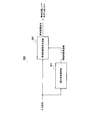
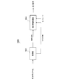
- FIG. 4 is a block diagram showing a configuration of adaptive band selection section 301 in the present embodiment.
- the pitch cycle calculation unit 401 calculates the pitch cycle of the input signal and outputs the calculated pitch cycle to the band limited frequency determination unit 402.
- the band limit frequency determination unit 402 uses the pitch period input from the pitch period calculation unit 401 to obtain a pitch frequency F0 represented by the reciprocal of the pitch period, and determines the band limit frequency Fcut using the obtained pitch frequency F0. To do.
- the band limiting frequency Fcut is set so as to increase when the pitch frequency F0 is low, and is set so as to decrease when the pitch frequency F0 is high.
- the band limit frequency Fcut is expressed by the following equation (1).
- Speech with a high pitch period tends to contain a lot of energy in a relatively ultra-wideband part, and therefore it tends to give a sense of noise when encoded with a band extension layer at a low bit rate. Therefore, in the case of a voice with a high pitch period, the band limit frequency Fcut is set lower than in the case of a voice (bass) with a low pitch period. On the other hand, voices with a low pitch period tend to have less energy in the ultra-wideband part than voices with a high pitch period, so that even when encoded with a band extension layer at a low bit rate, it is difficult to perceive noise. .
- the band limit frequency Fcut is set higher than that of a voice with a high pitch cycle (high pitch).
- the band limiting frequency Fcut is set higher than that of a voice with a high pitch cycle (high pitch).
- the band-limited frequency determining unit 402 outputs the determined band-limited frequency Fcut to the band-limited signal generating unit 302.
- the band limit signal generation unit 302 limits the band so as not to pass a higher band than the band limit frequency Fcut.
- the band limitation signal generation unit 302 limits the band by attenuating energy in a higher frequency range than the band limitation frequency Fcut.
- a band extension layer is used.
- the band of the input signal is adaptively limited according to the characteristics of the input signal.
- audio quality is more audibly important for lower frequency signals. For example, in a frequency band of 7 kHz or higher, a subjective quality difference due to a difference in signal bandwidth becomes difficult to feel.
- the noise feeling of the output signal is reduced by limiting the bandwidth of the input signal. At this time, the band feeling is lost due to the band limitation, but since the subjective quality difference due to the bandwidth difference is hardly felt, the quality as a whole is improved.
- FIG. 5 is a block diagram showing a configuration of speech decoding apparatus 500 according to Embodiment 1 of the present invention.
- Separating section 501 separates a bit stream input via a communication channel (not shown) into first layer encoded data and band extension layer encoded data, and converts the first layer encoded data to first The data is output to layer decoding section 502, and the band extension layer encoded data is output to band extension layer decoding section 503.
- a part of the encoded data for example, band extension layer encoded data
- the separation unit 501 is a case where only the first layer encoded data is included in the received encoded data, or when both the first layer encoded data and the band extension layer encoded data are included
- the determination result is output to the switching unit 505 as layer information.
- the layer information is, for example, “1” in the former case and “2” in the latter case. Note that, when all the encoded data is discarded, the speech decoding apparatus 500 performs a predetermined compensation process to generate an output signal.
- First layer decoding section 502 decodes the first layer encoded data input from demultiplexing section 501 to generate a first layer decoded signal, and adds the generated first layer decoded signal to adding section 504 and switching section 505. Output to.
- Band extension layer decoding section 503 performs a decoding process on the band extension layer encoded data input from separation section 501 to generate a band extension layer decoded signal, and outputs the generated band extension layer decoded signal to addition section 504.
- Adder 504 adds the first layer decoded signal input from first layer decoding section 502 and the band extension layer decoded signal input from band extension layer decoding section 503 to generate an addition decoded signal, and generates the generated addition The decoded signal is output to switching section 505.
- Switching section 505 refers to the layer information input from demultiplexing section 501 and decodes the first layer decoded signal when only the first layer encoded data is included (for example, when the layer information is “1”). The signal is output to the post-processing unit 506 as a signal. Also, the switching unit 505 refers to the layer information input from the separation unit 501 and includes both the first layer encoded data and the band extension layer encoded data (for example, when the layer information is “2”). ), The added decoded signal obtained by adding the first layer decoded signal and the band extension layer decoded signal input from the adding unit 504 is output to the post-processing unit 506 as a decoded signal.
- the post-processing unit 506 performs post-processing such as post filtering on the decoded signal input from the switching unit 505, and outputs the result as an output signal.
- the band limit frequency is adaptively adjusted according to the pitch period, and the band equal to or higher than the band limit frequency is excluded from the encoding target in the band extension layer, or the energy is reduced in the band extension layer. Decreasing the auditory importance by attenuating can prevent overall quality deterioration associated with encoding even if the bit rate is lowered.
- input signal is simply encoded in first layer encoding section 101.
- mode determination is made as to whether the input signal is speech or music, and the mode determination is performed.
- the information may be output to the adaptive band limiting unit 102, and the adaptive band limiting unit 102 may switch whether or not to perform band limiting depending on whether the input signal is speech or music. Specifically, it may be switched so that band limitation is performed when the input signal is sound and band limitation is not performed when the input signal is music.
- the adaptive band selection unit 301 uses a mathematical expression when determining the band limited frequency Fcut from the pitch frequency F0.
- the present invention is not limited to this, and the pitch frequency can be determined by referring to a table.
- the band limit frequency Fcut may be determined from F0.
- the table is designed so that the Fcut increases as the pitch frequency F0 of the input signal decreases, or the Fcut decreases as the pitch frequency F0 of the input signal increases.
- the band higher than the band limit frequency Fcut in the extension band part is band limited, but the present invention is not limited to this, and the predetermined bandwidth that affects the quality in the extension band part is band limited. Also good.
- the pitch period calculation unit 401 calculates the pitch period of the input signal.
- the present invention is not limited to this, and the first layer encoding unit 101 calculates the pitch period of the input signal to obtain the band. You may output to the limiting frequency determination part 402. FIG. In this case, the pitch period calculation unit 401 can be omitted.
- the present embodiment is characterized in that a spectrum is obtained by performing FFT (Fast Fourier Transform) analysis on an input signal, and a band limited frequency is determined using the obtained spectrum and a threshold value determined by a pitch frequency and a bit rate. Have.
- the bit rate is input from the outside of the speech encoding apparatus.
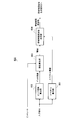
- FIG. 6 is a block diagram showing a configuration of adaptive band selection section 600 according to Embodiment 2 of the present invention.
- the speech encoding apparatus according to the present embodiment has the same configuration as that shown in FIG. Since the adaptive band limiting unit in the present embodiment has the same configuration as that of FIG. 3 except that it has an adaptive band selecting unit 600 instead of the adaptive band selecting unit 301, the description thereof is omitted.
- the speech decoding apparatus according to the present embodiment has the same configuration as that shown in FIG.
- the spectrum calculation unit 601 calculates the spectrum by performing FFT analysis on the input signal, and outputs the spectrum information of the calculated spectrum to the band limited frequency determination unit 604.
- the pitch cycle calculation unit 602 calculates the pitch cycle of the input signal and outputs the calculated pitch cycle to the threshold value calculation unit 603.
- the threshold calculation unit 603 calculates a threshold from the pitch period input from the pitch period calculation unit 602 and the input bit rate, and outputs the calculated threshold Ith to the band limited frequency determination unit 604.
- the bit rate is a preset value.
- the threshold value Ith is obtained from the following equation (2).
- the pitch frequency is represented by the reciprocal of the pitch period input from the pitch period calculation unit 602. From equation (2), the threshold value Ith increases as the bit rate increases, and decreases as the pitch frequency increases. Further, the bit rate may be a bit rate assigned to the entire codec or a bit rate assigned only to the band extension layer.
- the band limit frequency determination unit 604 determines a band limit frequency using the spectrum information input from the spectrum calculation unit 601 and the threshold value input from the threshold value calculation unit 603, and the determined band limit frequency is used as the band limit signal generation unit 302. Output to.
- FIG. 7 is a diagram illustrating a method for determining a band-limited frequency.
- FIG. 7 shows a case where the ultra wideband audio spectrum is divided into nine subbands E [0] to E [8]. Note that the ultra-wideband audio spectrum is not limited to being divided into nine subbands, and can be divided into any number of subbands. Further, the bandwidth of each subband is not limited to being equal, and may be different.
- the band-limited frequency determination unit 604 compares the subband energy ratio (Ef [k] / Eall) of the cumulative sum Ef [k] of each subband energy E [k] from the low band to the total energy Eall of all subbands. )
- k is a subband index represented by an integer from 0 to 8.
- the signal is output to the signal generator 302.
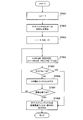
- FIG. 8 is a flowchart showing the operation of the band limited frequency determination unit 604.
- Band limited frequency determination section 604 first initializes the sum Eall of all subband energies to “0” (step ST801).
- the band limit frequency determination unit 604 obtains the total Eall of all subband energies (step ST802).
- the band-limited frequency determination unit 604 initializes the subband index k and the subband energy cumulative sum Ef [0] to 0 in order to obtain the cumulative subband energy sum Ef [k] ( Step ST803).
- the band limit frequency determination unit 604 obtains a cumulative sum Ef [k] of subband energy corresponding to the subband index k (step ST804), and a subband energy ratio (Ef [k]) obtained by using it. / Eall) and the threshold value Ith output from the threshold value calculation unit 603 are compared (step ST805).
- step ST805 If the subband energy ratio is equal to or less than the threshold Ith (step ST805: NO), the band limit frequency determination unit 604 increments the value of the subband index k (step ST806), and has the search for the predetermined range been completed? It is determined whether or not (step ST807).
- step ST807 NO
- the band limit frequency determination unit 604 repeats the processes of step ST804 to step ST807 until the subband energy ratio becomes larger than the threshold value Ith.
- step ST805 when the subband energy ratio exceeds the threshold value Ith (step ST805: YES), or when the search for a predetermined range is completed (step ST807: YES), the band limited frequency determination unit 604 Subband index k is output to band limited signal generation section 302 (step ST808).
- Each of the subband indexes k has a one-to-one correspondence with the upper end frequency of each subband, and this upper end frequency is regarded as a band limited frequency.
- the band is divided into a relatively large band and a small band in all bands, and a band with a small energy is divided.
- the audible importance is reduced by excluding the encoding target or by attenuating energy in a low-energy band.
- the spectrum calculation unit 601 calculates the spectrum by performing FFT analysis on the input signal.
- the present invention is not limited to this, and the LPC (Linear) generated by the first layer encoding unit is not limited thereto.
- the spectral envelope may be obtained using a Prediction coding) coefficient.
- FIG. 9 is a block diagram showing a modified example (speech encoding apparatus 900) of the speech encoding apparatus according to the present embodiment.
- speech coding apparatus 900 shown in FIG. 9 has adaptive band limiting section 901 instead of adaptive band limiting section 102, compared to speech coding apparatus 100 according to Embodiment 1 shown in FIG.
- FIG. 9 parts having the same configuration as in FIG.
- 1st layer encoding part 101 performs the encoding process of an input signal, and produces
- First layer encoding section 101 outputs the generated first layer encoded data to band extension layer encoding section 103 and multiplexing section 104, and adapts the LPC coefficients generated by first layer encoding section 101 The data is output to the band limiting unit 901.
- the LPC coefficient is calculated by, for example, an autocorrelation method.
- Adaptive band limiting section 901 selects a band to be limited in the band extension layer based on the input signal and the LPC coefficient input from first layer encoding section 101. Then, adaptive band limiting section 901 outputs a band limited signal obtained by limiting the selected band among the bands of the input signal to band enhancement layer encoding section 103. Details of the configuration of the adaptive band limiting unit 901 will be described later.
- Band extension layer encoding section 103 performs encoding processing of the extension band section using the first layer encoded data input from first layer encoding section 101 and the band limited signal input from adaptive band limiting section 901. To generate band enhancement layer encoded data. Band extension layer encoding section 103 outputs the generated band extension layer encoded data to multiplexing section 104.
- FIG. 10 is a block diagram showing the configuration of the adaptive band limiting unit 901. Note that adaptive band limiting section 901 shown in FIG. 10 has adaptive band selecting section 1001 instead of adaptive band selecting section 301, compared to adaptive band limiting section 102 in Embodiment 1 shown in FIG. In FIG. 10, parts having the same configuration as in FIG. Details of the configuration of the adaptive band selection unit 1001 will be described later.
- Adaptive band selection section 1001 analyzes the characteristics of the input signal, and selects a band to be limited in the input signal based on the analysis result and the LPC coefficient input from first layer encoding section 101.
- the adaptive band selection unit 1001 outputs information on the band to which the selected limitation is applied to the band limitation signal generation unit 302 as a band limitation frequency. Details of the configuration of the adaptive band selection unit 1001 will be described later.
- Band limit signal generation section 302 generates a band limit signal based on the input signal and the band limit frequency input from adaptive band selection section 1001, and outputs the generated band limit signal to band extension layer encoding section 103. Note that the configuration and operation of the band-limited signal generation unit 302 in the present embodiment are the same as those of the band-limited signal generation unit 302 in the first embodiment, and thus detailed description thereof is omitted.
- FIG. 11 is a block diagram showing a configuration of adaptive band selection section 1001 in the present embodiment. Note that adaptive band selection section 1001 shown in FIG. 11 adds spectrum envelope calculation section 1101 to adaptive band selection section 600 in the present embodiment shown in FIG. 6 except for spectrum calculation section 601. In FIG. 11, parts having the same configuration as in FIG.
- the spectrum envelope calculation unit 1101 estimates the spectrum envelope using the LPC coefficients input from the first layer encoding unit 101, and outputs the estimated spectrum envelope to the band limited frequency determination unit 604 as spectrum information. Based on this spectrum information, the band-limited frequency determination unit 604 can determine the subband energy ratio in the same manner as when the spectrum is determined by FFT analysis.
- spectrum envelope calculation section 1101 obtains a spectrum envelope using LPC coefficients, but the present invention is not limited to this, and LSP (Linear (Spectral Pairs), LSF other than LPC coefficients.
- Spectral envelopes can be obtained using (Linear Spectral Frequencies), ISP (Immitance Spectral Pairs) ISF (Immitance Spectral Frequencies) or PARCOR (Partial Auto Correlation) coefficients.
- the spectrum calculation unit calculates the spectrum by performing FFT analysis on the input signal.
- the present invention is not limited to this, and the DFT (Discrete Fourier Transform) and DCT (Discrete Cosine Transform) other than FFT are used. ), MDCT (Modified Discrete Cosine Transform), a filter bank, or the like.
- the pitch period of the input signal is calculated by the pitch period calculation unit 602.
- the present invention is not limited to this, and the first layer encoding unit 101 calculates the pitch period of the input signal and sets the threshold value. You may output to the calculation part 603. FIG. In this case, the pitch period calculation unit 602 can be omitted.
- the present embodiment is characterized in that the limited band is excluded from the encoding target by performing band limitation based on the comparison between the background noise spectrum in the unvoiced section and the speech spectrum in the voiced section. That is, the background noise spectrum is obtained in the unvoiced section, and the speech spectrum is obtained in the voiced section. In the voiced section, the voice spectrum in the band below the background noise level is masked by the background noise and can be regarded as not important for hearing, so the band below the background noise level is limited.
- FIG. 12 is a block diagram showing a configuration of adaptive band selection section 1200 according to Embodiment 3 of the present invention.
- the speech encoding apparatus according to the present embodiment has the same configuration as that shown in FIG.
- the adaptive band limiting unit 102 according to the present embodiment has the same configuration as that of FIG. 4 except that it has an adaptive band selection unit 1200 instead of the adaptive band selection unit 301, and thus the description thereof is omitted.
- the speech decoding apparatus according to the present embodiment has the same configuration as that shown in FIG.
- the spectrum calculation unit 1201 obtains the spectrum of the input signal by performing FFT analysis on the input signal, and outputs the spectrum information of the obtained spectrum to the switch unit 1203 and the band limited frequency determination unit 1205.
- the voice detection unit 1202 detects an unvoiced section or a voiced section using the input signal, and outputs detection information to the switch section 1203. For example, the voice detection unit 1202 outputs “0” to the switch unit 1203 as detection information in the case of an unvoiced section and “1” in the case of a voiced section.
- the switch unit 1203 performs switching using the detection information input from the voice detection unit 1202. Specifically, the switch unit 1203 outputs the spectrum information input from the spectrum calculation unit 1201 to the background noise spectrum calculation unit 1204 only when the detection information is a silent section (for example, when the detection information is “0”). On the other hand, when the detection information is a voiced section (for example, when the detection information is “1”), the switch unit 1203 turns off the switch and outputs nothing.
- the background noise spectrum calculation unit 1204 averages the subband energy in the spectrum information input from the switch unit 1203 for each subband during the frame of the silent section, and the background noise spectrum averaged for each subband The result is output to the limit frequency determination unit 1205.
- the background noise spectrum is averaged, for example, by the following equation (3).
- Nprev is updated by substituting Ne in the previous frame for Nprev.
- the band-limited frequency determination unit 1205 subtracts the averaged background noise spectrum Ne input from the background noise spectrum calculation unit 1204 in the logarithmic domain from the spectrum S of the spectrum information input from the spectrum calculation unit 1201 for each subband. Then, the band limit frequency determination unit 1205 outputs the frequency value when the subtracted value is negative to the band limit signal generation unit 302 as the band limit frequency Fcut. On the other hand, if the subtracted value does not become negative, the band limit frequency determination unit 1205 sets the value of the band limit frequency Fcut to 16 kHz and outputs the set value to the band limit signal generation unit 302. That is, no band limitation is performed.
- FIG. 13 is a diagram illustrating a method for determining a band-limited frequency in the present embodiment.
- the band-limited frequency determination unit 1205 detects the unvoiced and voiced intervals from the input signal shown in FIG. 13A, and performs the FFT analysis of the input signal in the unvoiced interval, thereby causing the background noise shown in FIG. Get the spectrum.
- the band limited frequency determination unit 1205 obtains a voice spectrum shown in FIG. 13C by performing FFT analysis of the input signal even in the voiced section.
- the band limited frequency determination unit 1205 compares the spectrum of FIG. 13B with the spectrum of FIG. 13C. Then, band-limited signal generation section 302 excludes a band whose voice spectrum is lower than the background noise spectrum level (a band equal to or higher than Fcut in FIG. 13D) from the encoding target, or the voice spectrum is background noise. The band is limited by attenuating the energy of the band below the spectrum level (in FIG. 13D, the band equal to or higher than Fcut).
- the band limit frequency is adaptively adjusted in accordance with the relationship between the level of the speech spectrum and the level of the background noise spectrum, so that the overall encoding associated with the coding can be achieved even if the bit rate is lowered. Quality deterioration can be prevented.
- the spectrum calculation unit calculates the spectrum by performing FFT analysis on the input signal, but the present invention is not limited to this, and uses DFT, DCT, MDCT, filter bank, or the like other than FFT. be able to.
- FIG. 14 is a block diagram showing a configuration of speech encoding apparatus 1400 that is not a scalable configuration.
- the present invention can also be applied to a speech encoding apparatus 1400 as shown in FIG.
- adaptive band limiting section 1401 selects a band to be limited in the band extension layer, and outputs a band limited signal in which the selected band is limited among the bands of the input signal to encoding section 1402.
- adaptive band limiting section 1401 can determine the band limiting frequency by adopting any one of the methods shown in the first to third embodiments. At this time, for example, when the band to be encoded by the encoding unit 1402 is a narrow band (0 Hz to 3.5 kHz), the lower limit of the band limited frequency determined by the adaptive band limiting unit 1401 is up to 3.5 kHz. Can take the value of
- the encoding unit 1402 encodes the band limited signal input from the adaptive band limiting unit 1401 to generate a bit stream, and outputs the generated bit stream to a communication path (not shown).
- the present embodiment is characterized in that a band is limited in the speech decoding apparatus.
- FIG. 15 is a block diagram showing a configuration of speech decoding apparatus 1500 according to the present embodiment.
- the decoding unit 1501 decodes a bit stream input via a communication channel (not shown) to generate a decoded signal, and outputs the generated decoded signal to the adaptive band limiting unit 1502.
- the decoding unit 1501 in this embodiment may have the same configuration as the speech decoding apparatus 500 in FIG. 5 as an example, and a detailed description thereof is omitted here.
- the adaptive band limiting unit 1502 selects a band to which the limitation is applied, and outputs a band limited signal in which the selected band is limited among the bands of the decoded signal input from the decoding unit 1501 as an output signal. At this time, adaptive band limiting section 1502 employs any one of the methods shown in the first to third embodiments to determine the band limited frequency.
- adaptive band limiting section 1502 selects a band to be limited based on the pitch period of the decoded signal input from decoding section 1501.
- adaptive band limiting section 1502 performs a FFT analysis on the decoded signal input from decoding section 1501, calculates a spectrum, and applies a band limit using the calculated spectrum and the threshold value obtained from equation (2). Select.
- adaptive band limiting section 1502 performs FFT analysis on the decoded signal input from decoding section 1501, calculates a spectrum, and averages the background noise spectrum from the spectrum calculated for each subband in the logarithmic domain. Subtraction is performed, and a frequency equal to or higher than the frequency when the subtracted value becomes negative is selected as a band to be limited.
- adaptive band limiting section 1502 has a configuration for selecting a band to be excluded that is wider as the pitch frequency is higher, or the encoding device has a scalable configuration.
- a configuration may be adopted in which a wider band for attenuating the energy of the expansion band is selected as the pitch frequency is higher.
- the adaptive band limiting unit 1502 can take a value up to 3.5 kHz as the lower limit of the band limiting frequency when the band to be decoded by the decoding unit 1501 is a narrow band (0 Hz to 3.5 kHz), for example.
- the speech decoding apparatus adaptively adjusts the band limit frequency and excludes a band equal to or higher than the band limit frequency from the encoding target in the band extension layer or attenuates energy in the band extension layer. By reducing the perceptual importance, it is possible to prevent the overall quality degradation accompanying encoding even if the bit rate is lowered.
- FIG. 16 is a block diagram showing speech decoding apparatus 1600 according to a modification of the present embodiment.
- Speech decoding apparatus 1600 uses adaptive band limiting section 1602 to determine the band limited frequency using the method of the second embodiment.
- the LPC coefficient generated by the decoding unit 1601 is used.
- the decoding unit 1601 generates a decoded signal by decoding a bitstream input via a communication channel (not shown), and outputs the generated decoded signal to the adaptive band limiting unit 1602. At this time, decoding section 1601 generates an LPC coefficient and outputs the generated LPC coefficient to adaptive band limiting section 1602.
- the LPC coefficient is calculated by, for example, an autocorrelation method.
- Other configurations and operations in the decoding unit 1601 are the same as those in the speech decoding apparatus 500 in FIG.
- Adaptive band limiting section 1602 selects a band to be restricted based on the decoded signal and LPC coefficient input from decoding section 1601, and selects the selected band from the band of the band extension layer decoded signal input from decoding section 1601. Add restrictions to Then, adaptive band limiting section 1602 outputs a band limited signal obtained by limiting the selected band as an output signal.
- FIG. 17 is a block diagram showing a configuration of adaptive band limiting section 1602 in a modification of the present embodiment.
- the adaptive band selection unit 1701 analyzes the characteristics of the decoded signal input from the decoding unit 1601, and selects a band to which the restriction is applied in the decoded signal based on the analysis result and the LPC coefficient input from the decoding unit 1601.
- the adaptive band selection unit 1701 outputs information on the band to which the selected limitation is applied to the band limitation signal generation unit 1702 as a band limitation frequency.
- the band limited signal generation unit 1702 generates a band limited signal based on the decoded signal input from the decoding unit 1601 and the band limited frequency input from the adaptive band selection unit 1701, and outputs the generated band limited signal as an output signal. .
- the band limited signal generation unit 1702 sets a frequency lower than the band limited frequency input from the adaptive band selection unit 1701 as a pass band, and limits the band in the decoded signal input from the decoding unit 1601. That is, the band limited signal generation unit 1702 outputs an input signal having a frequency lower than the band limited frequency selected by the adaptive band selection unit 1701 as an output signal (band limited signal).
- the band limited signal generation unit 1702 is configured by, for example, a low-pass filter.
- the band limited signal generation unit 1702 outputs, as an output signal (band limited signal), a signal obtained by attenuating energy in a higher band than the band limited frequency input from the adaptive band selecting unit 1701 among the input signals.
- the modification of the present embodiment is not limited to the case where the decoding unit 1601 has a scalable configuration, and can be applied to configurations other than the scalable configuration.
- Embodiments 1 to 4 described above a scalable configuration with two layers is used.
- the present invention is not limited to this, and is applicable to a scalable configuration with three or more layers.
- the input signal may be any of a voice signal, a music signal, or a signal in which voice and music are mixed.
- each functional block used in the description of the first to fourth embodiments is typically realized as an LSI which is an integrated circuit. These may be individually made into one chip, or may be made into one chip so as to include a part or all of them. Although referred to as LSI here, it may be referred to as IC, system LSI, super LSI, or ultra LSI depending on the degree of integration.
- the method of circuit integration is not limited to LSI, and implementation with a dedicated circuit or a general-purpose processor is also possible.
- An FPGA Field Programmable Gate Array
- a reconfigurable processor that can reconfigure the connection or setting of circuit cells inside the LSI may be used.
- the present invention is suitable for, for example, a speech encoding device, a speech decoding device, a speech encoding method, and a speech decoding method having a scalable configuration.
Landscapes
- Engineering & Computer Science (AREA)
- Physics & Mathematics (AREA)
- Signal Processing (AREA)
- Audiology, Speech & Language Pathology (AREA)
- Computational Linguistics (AREA)
- Health & Medical Sciences (AREA)
- Human Computer Interaction (AREA)
- Acoustics & Sound (AREA)
- Multimedia (AREA)
- Spectroscopy & Molecular Physics (AREA)
- Quality & Reliability (AREA)
- Computer Networks & Wireless Communication (AREA)
- Compression, Expansion, Code Conversion, And Decoders (AREA)
Abstract
Description
<音声符号化装置の構成>
図2は、本発明の実施の形態1に係る音声符号化装置100の構成を示すブロック図である。
図3は、本実施の形態における適応帯域制限部102の構成を示すブロック図である。
図4は、本実施の形態における適応帯域選択部301の構成を示すブロック図である。

図5は、本発明の実施の形態1における音声復号装置500の構成を示すブロック図である。
本実施の形態によれば、ピッチ周期に応じて帯域制限周波数を適応的に調整し、帯域制限周波数以上の帯域は、帯域拡張レイヤにおける符号化対象から除外するか、または帯域拡張レイヤにおいてエネルギーを減衰させて聴感的な重要度を下げることにより、ビットレートを低くしても符号化に伴う全体的な品質の劣化を防ぐことができる。
本実施の形態において、第1レイヤ符号化部101において入力信号を単に符号化したが、本発明はこれに限らず、入力信号が音声であるのか音楽であるのかをモード判定し、そのモード判定情報を適応帯域制限部102に出力し、適応帯域制限部102において入力信号が音声の場合と音楽の場合とによって帯域制限を行うか否かを切り替えてもよい。具体的には、入力信号が音声であった場合には帯域制限を行い、入力信号が音楽であった場合には帯域制限を行わないように切り替えてもよい。
本実施の形態は、入力信号をFFT(Fast Fourier Transform)分析することによりスペクトルを求め、求めたスペクトルと、ピッチ周波数及びビットレートによって決まる閾値とを用いて帯域制限周波数を決定する点に特徴を有する。ここでビットレートは、音声符号化装置の外部から入力される。
図6は、本発明の実施の形態2における適応帯域選択部600の構成を示すブロック図である。なお、本実施の形態における音声符号化装置は、図2と同一構成であるので、その説明を省略する。本実施の形態における適応帯域制限部は、適応帯域選択部301の代わりに適応帯域選択部600を有する以外は図3と同一構成であるので、その説明を省略する。また、本実施の形態における音声復号装置は、図5と同一構成であるので、その説明を省略する。
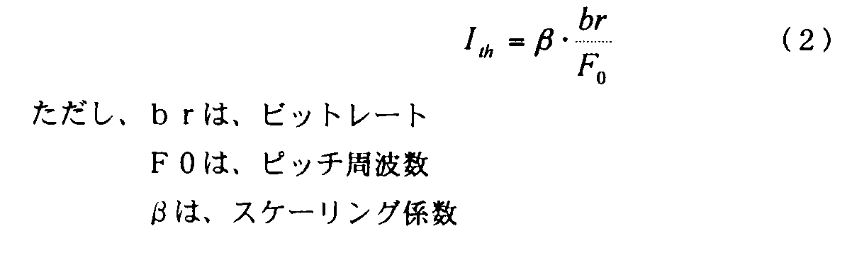
図7は、帯域制限周波数の決定方法を示す図である。図7は、超広帯域音声スペクトルを、E[0]~E[8]の9つのサブバンドに分割した場合を示す。なお、超広帯域音声スペクトルは、9つのサブバンドに分割する場合に限らず、任意の数のサブバンドに分割することができる。また、各サブバンドの帯域幅は、等幅である場合に限らず、異なる幅であってもよい。
図8は、帯域制限周波数決定部604の動作を示すフロー図である。
本実施の形態によれば、サブバンドエネルギー比に応じて帯域制限周波数を適応的に調整することにより、ビットレートを低くしても符号化に伴う全体的な品質の劣化を防ぐことができる。
本実施の形態において、スペクトル算出部601は、入力信号に対してFFT分析を行うことによりスペクトルを算出したが、本発明はこれに限らず、第1レイヤ符号化部で生成されるLPC(Linear Prediction coding)係数を用いてスペクトル包絡を求めてもよい。
本実施の形態において、スペクトル算出部は、入力信号に対してFFT分析を行ってスペクトルを算出したが、本発明はこれに限らず、FFT以外のDFT(Discrete Fourier Transform)、DCT(Discrete Cosine Transform)、MDCT(Modified Discrete Cosine Transform)またはフィルタバンクなどを使用することができる。
本実施の形態は、無声区間における背景雑音スペクトルと、有声区間における音声スペクトルとの比較に基づく帯域制限を行うことで、制限帯域を符号化対象から除外する点に特徴を有する。すなわち、無声区間においては背景雑音スペクトルを求め、有声区間では音声スペクトルを求める。有声区間においては、背景雑音のレベルを下回る帯域の音声スペクトルに関しては背景雑音にマスキングされ、聴感上重要ではないとみなすことができるので、この背景雑音のレベルを下回る帯域を制限する。
図12は、本発明の実施の形態3における適応帯域選択部1200の構成を示すブロック図である。なお、本実施の形態における音声符号化装置は、図2と同一構成であるので、その説明を省略する。また、本実施の形態における適応帯域制限部102は、適応帯域選択部301の代わりに適応帯域選択部1200を有する以外は図4と同一構成であるので、その説明を省略する。また、本実施の形態における音声復号装置は、図5と同一構成であるので、その説明を省略する。
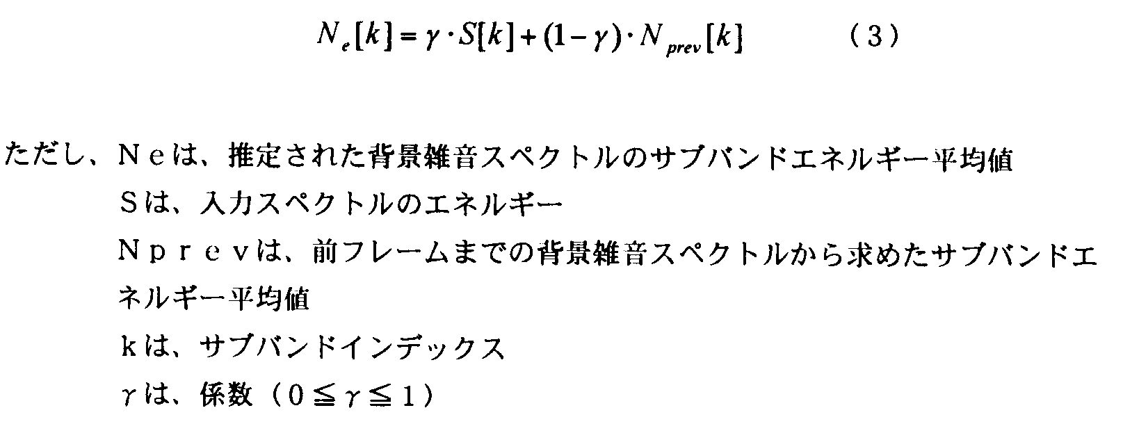
図13は、本実施の形態における帯域制限周波数の決定方法を示す図である。
本実施の形態によれば、音声スペクトルのレベルと背景雑音スペクトルのレベルとの関係に応じて帯域制限周波数を適応的に調整することにより、ビットレートを低くしても符号化に伴う全体的な品質の劣化を防ぐことができる。
本実施の形態において、スペクトル算出部は、入力信号に対してFFT分析を行ってスペクトルを算出したが、本発明はこれに限らず、FFT以外のDFT、DCT、MDCTまたはフィルタバンクなどを使用することができる。
上記の実施の形態1~実施の形態3において、音声符号化装置をスケーラブル構成として説明したが、本発明はこれに限らず、スケーラブル構成ではない符号化方式にも適用可能である。図14は、スケーラブル構成ではない音声符号化装置1400の構成を示すブロック図である。本発明は、図14に示すような音声符号化装置1400にも適用することができる。
本実施の形態は、音声復号装置において帯域に制限を加える点に特徴を有する。
本実施の形態による音声復号装置は、帯域制限周波数を適応的に調整し、帯域制限周波数以上の帯域を、帯域拡張レイヤにおける符号化対象から除外するか、または帯域拡張レイヤにおいてエネルギーを減衰させて聴感的な重要度を下げることにより、ビットレートを低くしても符号化に伴う全体的な品質の劣化を防ぐことができる。
図16は、本実施の形態の変形例に係る音声復号装置1600を示すブロック図である。
上記の実施の形態1~実施の形態4において、階層数が2のスケーラブル構成にしたが、本発明はこれに限らず、階層数が3以上のスケーラブル構成にも適用可能である。
102、901、1401、1502、1602 適応帯域制限部
103 帯域拡張レイヤ符号化部
104 多重化部
301、600、1001、1701 適応帯域選択部
302、1702 帯域制限信号生成部
401、602 ピッチ周期算出部
402、604、1205 帯域制限周波数決定部
601、1201 スペクトル算出部
603 閾値算出部
1101 スペクトル包絡算出部
1202 音声検出部
1203 スイッチ部
1204 背景雑音スペクトル算出部
1402 符号化部
1501、1601 復号部
Claims (20)
- 広帯域の信号を第1レイヤにおいて符号化するとともに、前記広帯域よりも高域である拡張帯域の信号を帯域拡張レイヤにおいて符号化する音声符号化装置であって、
前記拡張帯域において符号化の際に制限を加える帯域を選択する帯域選択手段と、
入力信号の帯域のうち前記選択された帯域に前記制限を加える帯域制限手段と、
を具備する音声符号化装置。 - 前記帯域選択手段は、
前記拡張帯域において符号化対象から除外する帯域を前記制限を加える帯域として選択し、
前記帯域制限手段は、
前記選択された帯域を符号化対象から除外することにより前記制限を加える、
請求項1記載の音声符号化装置。 - 前記帯域選択手段は、
前記拡張帯域においてエネルギーを減衰させる帯域を前記制限を加える帯域として選択し、
前記帯域制限手段は、
前記選択された帯域のエネルギーを減衰させることにより前記制限を加える、
請求項1記載の音声符号化装置。 - 前記帯域選択手段は、
前記入力信号のピッチ周波数が高いほど広い前記除外する帯域を選択する、
請求項2記載の音声符号化装置。 - 前記帯域選択手段は、
前記入力信号のピッチ周波数が高いほど広い前記エネルギーを減衰させる帯域を選択する、
請求項3記載の音声符号化装置。 - 前記帯域選択手段は、
前記入力信号のピッチ周波数とビットレートとにより閾値を求め、前記入力信号のスペクトルの各サブバンドエネルギーの総和に対する、低域からの各サブバンドエネルギーの累積和の比が、前記閾値より大きくなる帯域より高域を前記除外する帯域として選択する、
請求項2記載の音声符号化装置。 - 前記帯域選択手段は、
前記入力信号のピッチ周波数とビットレートとにより閾値を求め、前記入力信号のスペクトルの各サブバンドエネルギーの総和に対する、低域からの各サブバンドエネルギーの累積和の比が、前記閾値より大きくなる帯域より高域を前記エネルギーを減衰させる帯域として選択する、
請求項3記載の音声符号化装置。 - 前記帯域選択手段は、
前記入力信号の無声区間より背景雑音のスペクトルを推定し、前記入力信号のスペクトルが前記背景雑音のスペクトルよりも小さい帯域を前記除外する帯域として選択する、
請求項2記載の音声符号化装置。 - 前記帯域選択手段は、
前記入力信号の無声区間より背景雑音のスペクトルを推定し、前記入力信号のスペクトルが前記背景雑音のスペクトルよりも小さい帯域を前記エネルギーを減衰させる帯域として選択する、
請求項3記載の音声符号化装置。 - 符号化装置において生成された、広帯域の信号を符号化することによって得られた第1レイヤ符号化情報を第1レイヤにおいて復号し、前記広帯域よりも高域である拡張帯域の信号を符号化することによって得られた帯域拡張レイヤ符号化情報を帯域拡張レイヤにおいて復号する音声復号装置であって、
前記拡張帯域において出力の際に制限を加える帯域を選択する帯域選択手段と、
復号信号の帯域のうち前記選択された帯域に前記制限を加える帯域制限手段と、
を具備する音声復号装置。 - 前記帯域選択手段は、
前記拡張帯域において出力対象から除外する帯域を前記制限を加える帯域として選択し、
前記帯域制限手段は、
前記選択された帯域を出力対象から除外することにより前記制限を加える、
請求項10記載の音声復号装置。 - 前記帯域選択手段は、
前記拡張帯域においてエネルギーを減衰させる帯域を前記制限を加える帯域として選択し、
前記帯域制限手段は、
前記選択された帯域のエネルギーを減衰させることにより前記制限を加える、
請求項10記載の音声復号装置。 - 前記帯域選択手段は、
前記復号信号のピッチ周波数が高いほど広い前記除外する帯域を選択する、
請求項11記載の音声復号装置。 - 前記帯域選択手段は、
前記復号信号のピッチ周波数が高いほど広い前記エネルギーを減衰させる帯域を選択する、
請求項12記載の音声復号装置。 - 前記帯域選択手段は、
前記復号信号のピッチ周波数とビットレートとにより閾値を求め、前記入力信号のスペクトルの各サブバンドエネルギーの総和に対する、低域からの各サブバンドエネルギーの累積和の比が、前記閾値より大きくなる帯域より高域を前記除外する帯域として選択する、
請求項11記載の音声復号装置。 - 前記帯域選択手段は、
前記復号信号のピッチ周波数とビットレートとにより閾値を求め、前記入力信号のスペクトルの各サブバンドエネルギーの総和に対する、低域からの各サブバンドエネルギーの累積和の比が、前記閾値より大きくなる帯域より高域を前記エネルギーを減衰させる帯域として選択する、
請求項12記載の音声復号装置。 - 前記帯域選択手段は、
前記復号信号の無声区間より背景雑音のスペクトルを推定し、前記入力信号のスペクトルが前記背景雑音のスペクトルよりも小さい帯域を前記除外する帯域として選択する、
請求項11記載の音声復号装置。 - 前記帯域選択手段は、
前記復号信号の無声区間より背景雑音のスペクトルを推定し、前記入力信号のスペクトルが前記背景雑音のスペクトルよりも小さい帯域を前記エネルギーを減衰させる帯域として選択する、
請求項12記載の音声復号装置。 - 広帯域の信号を第1レイヤにおいて符号化するとともに、前記広帯域よりも高域である拡張帯域の信号を帯域拡張レイヤにおいて符号化する音声符号化方法であって、
前記拡張帯域において符号化の際に制限を加える帯域を選択するステップと、
入力信号の帯域のうち前記選択された帯域に制限を加えるステップと、
を具備する音声符号化方法。 - 広帯域の信号を第1レイヤにおいて復号するとともに、前記広帯域よりも高域である拡張帯域の信号を帯域拡張レイヤにおいて復号する音声復号方法であって、
前記拡張帯域において出力の際に制限を加える帯域を選択するステップと、
復号信号の帯域のうち前記選択された帯域に前記制限を加えるステップと、
を具備する音声復号方法。
Priority Applications (3)
| Application Number | Priority Date | Filing Date | Title |
|---|---|---|---|
| JP2013519367A JP5986565B2 (ja) | 2011-06-09 | 2012-05-25 | 音声符号化装置、音声復号装置、音声符号化方法及び音声復号方法 |
| EP12796725.5A EP2709103B1 (en) | 2011-06-09 | 2012-05-25 | Voice coding device, voice decoding device, voice coding method and voice decoding method |
| US14/123,841 US9264094B2 (en) | 2011-06-09 | 2012-05-25 | Voice coding device, voice decoding device, voice coding method and voice decoding method |
Applications Claiming Priority (4)
| Application Number | Priority Date | Filing Date | Title |
|---|---|---|---|
| JP2011129428 | 2011-06-09 | ||
| JP2011-129428 | 2011-06-09 | ||
| JP2011172393 | 2011-08-05 | ||
| JP2011-172393 | 2011-08-05 |
Publications (1)
| Publication Number | Publication Date |
|---|---|
| WO2012169133A1 true WO2012169133A1 (ja) | 2012-12-13 |
Family
ID=47295725
Family Applications (1)
| Application Number | Title | Priority Date | Filing Date |
|---|---|---|---|
| PCT/JP2012/003409 Ceased WO2012169133A1 (ja) | 2011-06-09 | 2012-05-25 | 音声符号化装置、音声復号装置、音声符号化方法及び音声復号方法 |
Country Status (4)
| Country | Link |
|---|---|
| US (1) | US9264094B2 (ja) |
| EP (1) | EP2709103B1 (ja) |
| JP (1) | JP5986565B2 (ja) |
| WO (1) | WO2012169133A1 (ja) |
Cited By (1)
| Publication number | Priority date | Publication date | Assignee | Title |
|---|---|---|---|---|
| CN104681032A (zh) * | 2013-11-28 | 2015-06-03 | 中国移动通信集团公司 | 一种语音通信方法和设备 |
Families Citing this family (8)
| Publication number | Priority date | Publication date | Assignee | Title |
|---|---|---|---|---|
| US9208798B2 (en) * | 2012-04-09 | 2015-12-08 | Board Of Regents, The University Of Texas System | Dynamic control of voice codec data rate |
| JP6335190B2 (ja) | 2012-12-21 | 2018-05-30 | フラウンホーファー−ゲゼルシャフト・ツール・フェルデルング・デル・アンゲヴァンテン・フォルシュング・アインゲトラーゲネル・フェライン | 低ビットレートで背景ノイズをモデル化するためのコンフォートノイズ付加 |
| US9697843B2 (en) | 2014-04-30 | 2017-07-04 | Qualcomm Incorporated | High band excitation signal generation |
| WO2020003727A1 (ja) | 2018-06-28 | 2020-01-02 | ソニー株式会社 | 復号装置、復号方法、プログラム |
| CN112313603B (zh) | 2018-06-28 | 2024-05-17 | 索尼公司 | 编码装置、编码方法、解码装置、解码方法和程序 |
| US11823557B2 (en) | 2018-07-03 | 2023-11-21 | Sony Corporation | Encoding apparatus, encoding method, decoding apparatus, decoding method, transmission system, receiving apparatus, and program |
| KR20250129118A (ko) * | 2018-08-08 | 2025-08-28 | 소니그룹주식회사 | 복호 장치, 복호 방법, 프로그램 |
| US20230110255A1 (en) * | 2021-10-12 | 2023-04-13 | Zoom Video Communications, Inc. | Audio super resolution |
Citations (6)
| Publication number | Priority date | Publication date | Assignee | Title |
|---|---|---|---|---|
| JPH07327014A (ja) * | 1994-06-01 | 1995-12-12 | Matsushita Electric Ind Co Ltd | オーディオ信号高能率符号化装置 |
| JPH09127987A (ja) * | 1995-10-26 | 1997-05-16 | Sony Corp | 信号符号化方法及び装置 |
| JP2008107415A (ja) * | 2006-10-23 | 2008-05-08 | Fujitsu Ltd | 符号化装置 |
| JP2010224180A (ja) * | 2009-03-23 | 2010-10-07 | Oki Electric Ind Co Ltd | 帯域拡張装置、方法及びプログラム、並びに、量子化雑音学習装置、方法及びプログラム |
| JP2011129428A (ja) | 2009-12-18 | 2011-06-30 | Toyota Motor Corp | 蓄電素子のホルダ |
| JP2011172393A (ja) | 2010-02-19 | 2011-09-01 | Sumitomo Wiring Syst Ltd | バスバー回路構造体 |
Family Cites Families (24)
| Publication number | Priority date | Publication date | Assignee | Title |
|---|---|---|---|---|
| JP3134455B2 (ja) * | 1992-01-29 | 2001-02-13 | ソニー株式会社 | 高能率符号化装置及び方法 |
| TW321810B (ja) | 1995-10-26 | 1997-12-01 | Sony Co Ltd | |
| SE512719C2 (sv) * | 1997-06-10 | 2000-05-02 | Lars Gustaf Liljeryd | En metod och anordning för reduktion av dataflöde baserad på harmonisk bandbreddsexpansion |
| US6539355B1 (en) * | 1998-10-15 | 2003-03-25 | Sony Corporation | Signal band expanding method and apparatus and signal synthesis method and apparatus |
| GB2351889B (en) * | 1999-07-06 | 2003-12-17 | Ericsson Telefon Ab L M | Speech band expansion |
| FI115329B (fi) * | 2000-05-08 | 2005-04-15 | Nokia Corp | Menetelmä ja järjestely lähdesignaalin kaistanleveyden vaihtamiseksi tietoliikenneyhteydessä, jossa on valmiudet useisiin kaistanleveyksiin |
| US7330814B2 (en) * | 2000-05-22 | 2008-02-12 | Texas Instruments Incorporated | Wideband speech coding with modulated noise highband excitation system and method |
| JP3576935B2 (ja) * | 2000-07-21 | 2004-10-13 | 株式会社ケンウッド | 周波数間引き装置、周波数間引き方法及び記録媒体 |
| JP2002169599A (ja) * | 2000-11-30 | 2002-06-14 | Toshiba Corp | ノイズ抑制方法及び電子機器 |
| ATE320651T1 (de) * | 2001-05-08 | 2006-04-15 | Koninkl Philips Electronics Nv | Kodieren eines audiosignals |
| JP4119696B2 (ja) | 2001-08-10 | 2008-07-16 | 松下電器産業株式会社 | 送信装置、受信装置及び無線通信方法 |
| US7162415B2 (en) * | 2001-11-06 | 2007-01-09 | The Regents Of The University Of California | Ultra-narrow bandwidth voice coding |
| US7447631B2 (en) * | 2002-06-17 | 2008-11-04 | Dolby Laboratories Licensing Corporation | Audio coding system using spectral hole filling |
| CN100508030C (zh) * | 2003-06-30 | 2009-07-01 | 皇家飞利浦电子股份有限公司 | 一种编码/解码音频信号的方法及相应设备 |
| JP4222250B2 (ja) * | 2004-04-26 | 2009-02-12 | ヤマハ株式会社 | 圧縮楽音データ再生装置 |
| US8260611B2 (en) * | 2005-04-01 | 2012-09-04 | Qualcomm Incorporated | Systems, methods, and apparatus for highband excitation generation |
| ATE528748T1 (de) * | 2006-01-31 | 2011-10-15 | Nuance Communications Inc | Verfahren und entsprechendes system zur erweiterung der spektralen bandbreite eines sprachsignals |
| US20080300866A1 (en) * | 2006-05-31 | 2008-12-04 | Motorola, Inc. | Method and system for creation and use of a wideband vocoder database for bandwidth extension of voice |
| CN101903943A (zh) * | 2008-01-01 | 2010-12-01 | Lg电子株式会社 | 用于处理信号的方法和装置 |
| JP5337381B2 (ja) * | 2008-01-18 | 2013-11-06 | 富士フイルム株式会社 | メロシアニン色素及び光電変換素子 |
| WO2010028301A1 (en) * | 2008-09-06 | 2010-03-11 | GH Innovation, Inc. | Spectrum harmonic/noise sharpness control |
| US8532998B2 (en) * | 2008-09-06 | 2013-09-10 | Huawei Technologies Co., Ltd. | Selective bandwidth extension for encoding/decoding audio/speech signal |
| GB2476041B (en) * | 2009-12-08 | 2017-03-01 | Skype | Encoding and decoding speech signals |
| US8738385B2 (en) * | 2010-10-20 | 2014-05-27 | Broadcom Corporation | Pitch-based pre-filtering and post-filtering for compression of audio signals |
-
2012
- 2012-05-25 WO PCT/JP2012/003409 patent/WO2012169133A1/ja not_active Ceased
- 2012-05-25 US US14/123,841 patent/US9264094B2/en active Active
- 2012-05-25 EP EP12796725.5A patent/EP2709103B1/en active Active
- 2012-05-25 JP JP2013519367A patent/JP5986565B2/ja active Active
Patent Citations (6)
| Publication number | Priority date | Publication date | Assignee | Title |
|---|---|---|---|---|
| JPH07327014A (ja) * | 1994-06-01 | 1995-12-12 | Matsushita Electric Ind Co Ltd | オーディオ信号高能率符号化装置 |
| JPH09127987A (ja) * | 1995-10-26 | 1997-05-16 | Sony Corp | 信号符号化方法及び装置 |
| JP2008107415A (ja) * | 2006-10-23 | 2008-05-08 | Fujitsu Ltd | 符号化装置 |
| JP2010224180A (ja) * | 2009-03-23 | 2010-10-07 | Oki Electric Ind Co Ltd | 帯域拡張装置、方法及びプログラム、並びに、量子化雑音学習装置、方法及びプログラム |
| JP2011129428A (ja) | 2009-12-18 | 2011-06-30 | Toyota Motor Corp | 蓄電素子のホルダ |
| JP2011172393A (ja) | 2010-02-19 | 2011-09-01 | Sumitomo Wiring Syst Ltd | バスバー回路構造体 |
Non-Patent Citations (1)
| Title |
|---|
| See also references of EP2709103A4 |
Cited By (1)
| Publication number | Priority date | Publication date | Assignee | Title |
|---|---|---|---|---|
| CN104681032A (zh) * | 2013-11-28 | 2015-06-03 | 中国移动通信集团公司 | 一种语音通信方法和设备 |
Also Published As
| Publication number | Publication date |
|---|---|
| US9264094B2 (en) | 2016-02-16 |
| EP2709103B1 (en) | 2015-10-07 |
| JP5986565B2 (ja) | 2016-09-06 |
| EP2709103A1 (en) | 2014-03-19 |
| JPWO2012169133A1 (ja) | 2015-02-23 |
| US20140122065A1 (en) | 2014-05-01 |
| EP2709103A4 (en) | 2014-03-26 |
Similar Documents
| Publication | Publication Date | Title |
|---|---|---|
| JP5986565B2 (ja) | 音声符号化装置、音声復号装置、音声符号化方法及び音声復号方法 | |
| US10559313B2 (en) | Speech/audio signal processing method and apparatus | |
| RU2658892C2 (ru) | Устройство и способ для расширения диапазона частот для акустических сигналов | |
| US7983904B2 (en) | Scalable decoding apparatus and scalable encoding apparatus | |
| US10217470B2 (en) | Bandwidth extension system and approach | |
| JP5706445B2 (ja) | 符号化装置、復号装置およびそれらの方法 | |
| CN110706715B (zh) | 信号编码和解码的方法和设备 | |
| ES2706148T3 (es) | Dispositivo de codificación de audio vocal, dispositivo de decodificación de audio vocal, procedimiento de codificación de audio vocal, y procedimiento de decodificación de audio vocal | |
| JP5171256B2 (ja) | ステレオ符号化装置、ステレオ復号装置、及びステレオ符号化方法 | |
| AU2011282276A1 (en) | Spectrum flatness control for bandwidth extension | |
| CN112119457A (zh) | 可截断的预测编码 | |
| KR20080049085A (ko) | 음성 부호화 장치 및 음성 부호화 방법 | |
| JPWO2007126015A1 (ja) | 音声符号化装置、音声復号化装置、およびこれらの方法 | |
| WO2012066727A1 (ja) | ステレオ信号符号化装置、ステレオ信号復号装置、ステレオ信号符号化方法及びステレオ信号復号方法 | |
| US8599981B2 (en) | Post-filter, decoding device, and post-filter processing method | |
| US20140288925A1 (en) | Bandwidth extension of audio signals | |
| JP2011501228A (ja) | 知覚モデルの適応的調整 | |
| JP6082703B2 (ja) | 音声復号装置及び音声復号方法 | |
| WO2015151451A1 (ja) | 符号化装置、復号装置、符号化方法、復号方法、およびプログラム | |
| JP5295380B2 (ja) | 符号化装置、復号化装置およびこれらの方法 | |
| Gibson | Challenges in speech coding research | |
| HK1190838B (en) | Signal coding and decoding method and equipment thereof | |
| HK1190838A (en) | Signal coding and decoding method and equipment thereof |
Legal Events
| Date | Code | Title | Description |
|---|---|---|---|
| 121 | Ep: the epo has been informed by wipo that ep was designated in this application |
Ref document number: 12796725 Country of ref document: EP Kind code of ref document: A1 |
|
| ENP | Entry into the national phase |
Ref document number: 2013519367 Country of ref document: JP Kind code of ref document: A |
|
| WWE | Wipo information: entry into national phase |
Ref document number: 14123841 Country of ref document: US |
|
| NENP | Non-entry into the national phase |
Ref country code: DE |
|
| WWE | Wipo information: entry into national phase |
Ref document number: 2012796725 Country of ref document: EP |