WO2012172644A1 - ガイダンス装置、ガイダンス方法 - Google Patents
ガイダンス装置、ガイダンス方法 Download PDFInfo
- Publication number
- WO2012172644A1 WO2012172644A1 PCT/JP2011/063598 JP2011063598W WO2012172644A1 WO 2012172644 A1 WO2012172644 A1 WO 2012172644A1 JP 2011063598 W JP2011063598 W JP 2011063598W WO 2012172644 A1 WO2012172644 A1 WO 2012172644A1
- Authority
- WO
- WIPO (PCT)
- Prior art keywords
- mode
- guidance
- engine
- power supply
- vehicle
- Prior art date
- Legal status (The legal status is an assumption and is not a legal conclusion. Google has not performed a legal analysis and makes no representation as to the accuracy of the status listed.)
- Ceased
Links
Images






Classifications
-
- B—PERFORMING OPERATIONS; TRANSPORTING
- B60—VEHICLES IN GENERAL
- B60R—VEHICLES, VEHICLE FITTINGS, OR VEHICLE PARTS, NOT OTHERWISE PROVIDED FOR
- B60R16/00—Electric or fluid circuits specially adapted for vehicles and not otherwise provided for; Arrangement of elements of electric or fluid circuits specially adapted for vehicles and not otherwise provided for
- B60R16/02—Electric or fluid circuits specially adapted for vehicles and not otherwise provided for; Arrangement of elements of electric or fluid circuits specially adapted for vehicles and not otherwise provided for electric constitutive elements
- B60R16/023—Electric or fluid circuits specially adapted for vehicles and not otherwise provided for; Arrangement of elements of electric or fluid circuits specially adapted for vehicles and not otherwise provided for electric constitutive elements for transmission of signals between vehicle parts or subsystems
- B60R16/0231—Circuits relating to the driving or the functioning of the vehicle
- B60R16/0232—Circuits relating to the driving or the functioning of the vehicle for measuring vehicle parameters and indicating critical, abnormal or dangerous conditions
-
- B—PERFORMING OPERATIONS; TRANSPORTING
- B60—VEHICLES IN GENERAL
- B60W—CONJOINT CONTROL OF VEHICLE SUB-UNITS OF DIFFERENT TYPE OR DIFFERENT FUNCTION; CONTROL SYSTEMS SPECIALLY ADAPTED FOR HYBRID VEHICLES; ROAD VEHICLE DRIVE CONTROL SYSTEMS FOR PURPOSES NOT RELATED TO THE CONTROL OF A PARTICULAR SUB-UNIT
- B60W50/00—Details of control systems for road vehicle drive control not related to the control of a particular sub-unit, e.g. process diagnostic or vehicle driver interfaces
- B60W50/08—Interaction between the driver and the control system
- B60W50/14—Means for informing the driver, warning the driver or prompting a driver intervention
-
- B—PERFORMING OPERATIONS; TRANSPORTING
- B60—VEHICLES IN GENERAL
- B60R—VEHICLES, VEHICLE FITTINGS, OR VEHICLE PARTS, NOT OTHERWISE PROVIDED FOR
- B60R16/00—Electric or fluid circuits specially adapted for vehicles and not otherwise provided for; Arrangement of elements of electric or fluid circuits specially adapted for vehicles and not otherwise provided for
- B60R16/02—Electric or fluid circuits specially adapted for vehicles and not otherwise provided for; Arrangement of elements of electric or fluid circuits specially adapted for vehicles and not otherwise provided for electric constitutive elements
-
- B—PERFORMING OPERATIONS; TRANSPORTING
- B60—VEHICLES IN GENERAL
- B60W—CONJOINT CONTROL OF VEHICLE SUB-UNITS OF DIFFERENT TYPE OR DIFFERENT FUNCTION; CONTROL SYSTEMS SPECIALLY ADAPTED FOR HYBRID VEHICLES; ROAD VEHICLE DRIVE CONTROL SYSTEMS FOR PURPOSES NOT RELATED TO THE CONTROL OF A PARTICULAR SUB-UNIT
- B60W50/00—Details of control systems for road vehicle drive control not related to the control of a particular sub-unit, e.g. process diagnostic or vehicle driver interfaces
- B60W50/08—Interaction between the driver and the control system
- B60W50/087—Interaction between the driver and the control system where the control system corrects or modifies a request from the driver
-
- F—MECHANICAL ENGINEERING; LIGHTING; HEATING; WEAPONS; BLASTING
- F02—COMBUSTION ENGINES; HOT-GAS OR COMBUSTION-PRODUCT ENGINE PLANTS
- F02N—STARTING OF COMBUSTION ENGINES; STARTING AIDS FOR SUCH ENGINES, NOT OTHERWISE PROVIDED FOR
- F02N11/00—Starting of engines by means of electric motors
- F02N11/08—Circuits specially adapted for starting of engines
- F02N11/0803—Circuits specially adapted for starting of engines characterised by means for initiating engine start or stop
-
- F—MECHANICAL ENGINEERING; LIGHTING; HEATING; WEAPONS; BLASTING
- F02—COMBUSTION ENGINES; HOT-GAS OR COMBUSTION-PRODUCT ENGINE PLANTS
- F02N—STARTING OF COMBUSTION ENGINES; STARTING AIDS FOR SUCH ENGINES, NOT OTHERWISE PROVIDED FOR
- F02N11/00—Starting of engines by means of electric motors
- F02N11/08—Circuits specially adapted for starting of engines
- F02N11/0814—Circuits specially adapted for starting of engines comprising means for controlling automatic idle-start-stop
-
- B—PERFORMING OPERATIONS; TRANSPORTING
- B60—VEHICLES IN GENERAL
- B60K—ARRANGEMENT OR MOUNTING OF PROPULSION UNITS OR OF TRANSMISSIONS IN VEHICLES; ARRANGEMENT OR MOUNTING OF PLURAL DIVERSE PRIME-MOVERS IN VEHICLES; AUXILIARY DRIVES FOR VEHICLES; INSTRUMENTATION OR DASHBOARDS FOR VEHICLES; ARRANGEMENTS IN CONNECTION WITH COOLING, AIR INTAKE, GAS EXHAUST OR FUEL SUPPLY OF PROPULSION UNITS IN VEHICLES
- B60K28/00—Safety devices for propulsion-unit control, specially adapted for, or arranged in, vehicles, e.g. preventing fuel supply or ignition in the event of potentially dangerous conditions
- B60K2028/003—Safety devices for propulsion-unit control, specially adapted for, or arranged in, vehicles, e.g. preventing fuel supply or ignition in the event of potentially dangerous conditions inhibiting the starter motor, e.g. by controlling ignition or park lock circuits
-
- B—PERFORMING OPERATIONS; TRANSPORTING
- B60—VEHICLES IN GENERAL
- B60K—ARRANGEMENT OR MOUNTING OF PROPULSION UNITS OR OF TRANSMISSIONS IN VEHICLES; ARRANGEMENT OR MOUNTING OF PLURAL DIVERSE PRIME-MOVERS IN VEHICLES; AUXILIARY DRIVES FOR VEHICLES; INSTRUMENTATION OR DASHBOARDS FOR VEHICLES; ARRANGEMENTS IN CONNECTION WITH COOLING, AIR INTAKE, GAS EXHAUST OR FUEL SUPPLY OF PROPULSION UNITS IN VEHICLES
- B60K28/00—Safety devices for propulsion-unit control, specially adapted for, or arranged in, vehicles, e.g. preventing fuel supply or ignition in the event of potentially dangerous conditions
- B60K2028/006—Safety devices for propulsion-unit control, specially adapted for, or arranged in, vehicles, e.g. preventing fuel supply or ignition in the event of potentially dangerous conditions disconnecting the electric power supply, e.g. the vehicle battery
-
- B—PERFORMING OPERATIONS; TRANSPORTING
- B60—VEHICLES IN GENERAL
- B60W—CONJOINT CONTROL OF VEHICLE SUB-UNITS OF DIFFERENT TYPE OR DIFFERENT FUNCTION; CONTROL SYSTEMS SPECIALLY ADAPTED FOR HYBRID VEHICLES; ROAD VEHICLE DRIVE CONTROL SYSTEMS FOR PURPOSES NOT RELATED TO THE CONTROL OF A PARTICULAR SUB-UNIT
- B60W2540/00—Input parameters relating to occupants
- B60W2540/06—Ignition switch
-
- B—PERFORMING OPERATIONS; TRANSPORTING
- B60—VEHICLES IN GENERAL
- B60W—CONJOINT CONTROL OF VEHICLE SUB-UNITS OF DIFFERENT TYPE OR DIFFERENT FUNCTION; CONTROL SYSTEMS SPECIALLY ADAPTED FOR HYBRID VEHICLES; ROAD VEHICLE DRIVE CONTROL SYSTEMS FOR PURPOSES NOT RELATED TO THE CONTROL OF A PARTICULAR SUB-UNIT
- B60W50/00—Details of control systems for road vehicle drive control not related to the control of a particular sub-unit, e.g. process diagnostic or vehicle driver interfaces
- B60W50/02—Ensuring safety in case of control system failures, e.g. by diagnosing, circumventing or fixing failures
- B60W50/029—Adapting to failures or work around with other constraints, e.g. circumvention by avoiding use of failed parts
-
- F—MECHANICAL ENGINEERING; LIGHTING; HEATING; WEAPONS; BLASTING
- F02—COMBUSTION ENGINES; HOT-GAS OR COMBUSTION-PRODUCT ENGINE PLANTS
- F02N—STARTING OF COMBUSTION ENGINES; STARTING AIDS FOR SUCH ENGINES, NOT OTHERWISE PROVIDED FOR
- F02N11/00—Starting of engines by means of electric motors
- F02N11/10—Safety devices
- F02N11/101—Safety devices for preventing engine starter actuation or engagement
-
- F—MECHANICAL ENGINEERING; LIGHTING; HEATING; WEAPONS; BLASTING
- F02—COMBUSTION ENGINES; HOT-GAS OR COMBUSTION-PRODUCT ENGINE PLANTS
- F02N—STARTING OF COMBUSTION ENGINES; STARTING AIDS FOR SUCH ENGINES, NOT OTHERWISE PROVIDED FOR
- F02N2200/00—Parameters used for control of starting apparatus
- F02N2200/10—Parameters used for control of starting apparatus said parameters being related to driver demands or status
- F02N2200/102—Brake pedal position
-
- Y—GENERAL TAGGING OF NEW TECHNOLOGICAL DEVELOPMENTS; GENERAL TAGGING OF CROSS-SECTIONAL TECHNOLOGIES SPANNING OVER SEVERAL SECTIONS OF THE IPC; TECHNICAL SUBJECTS COVERED BY FORMER USPC CROSS-REFERENCE ART COLLECTIONS [XRACs] AND DIGESTS
- Y02—TECHNOLOGIES OR APPLICATIONS FOR MITIGATION OR ADAPTATION AGAINST CLIMATE CHANGE
- Y02T—CLIMATE CHANGE MITIGATION TECHNOLOGIES RELATED TO TRANSPORTATION
- Y02T10/00—Road transport of goods or passengers
- Y02T10/10—Internal combustion engine [ICE] based vehicles
- Y02T10/40—Engine management systems
Definitions
- the present invention relates to a guidance device that teaches a vehicle operation method, and more particularly, to a guidance device that teaches a driving force starting method.
- a vehicle powered by an internal combustion engine may stop the engine while driving (hereinafter referred to as an engine stall). Further, a vehicle (EV) powered by an electric motor or a vehicle (HV) partially powered by an electric motor may be in a Ready-OFF state in which driving force cannot be transmitted to wheels during traveling. Such a situation occurs when, for example, the gas runs out, an emergency stop operation is performed, or an external action is received.
- a vehicle (EV) powered by an electric motor or a vehicle (HV) partially powered by an electric motor may be in a Ready-OFF state in which driving force cannot be transmitted to wheels during traveling. Such a situation occurs when, for example, the gas runs out, an emergency stop operation is performed, or an external action is received.
- Patent Document 1 discloses information for monitoring the state of electrical appliances of a vehicle, issuing an emergency treatment method to a driver on condition that the monitoring data exceeds a threshold value, and stopping or driving the vehicle safely. Is disclosed.
- the vehicle can be immediately restored to a travelable state.
- the emergency stop operation button is arranged at a position where it can be operated from the driver's seat, it can be operated unconsciously except when the driver consciously performs the emergency stop operation.
- the driver who operates unconsciously cannot understand why the engine is in the engine stall or Ready-OFF state, and cannot perform an operation for recovering to the travelable state.
- the vehicle guidance device described in Patent Document 1 only monitors monitoring data, and there is a problem that no consideration is given to a case where an emergency stop operation is performed unconsciously. JP 2003-089332 A
- an object of the present invention is to provide a guidance device capable of teaching appropriate guidance when it becomes difficult to travel due to a driver's operation.
- the present invention is a guidance device that teaches a vehicle operating method, and receives an operation for starting or stopping an engine, or an operation receiving means for receiving a start or stop operation for a traveling system including at least an electric motor, and the operation receiving means Power control means for controlling to a power mode determined according to the operation received by the vehicle and the vehicle state, stop detection means for detecting engine stop or travel system stop during travel, engine stop or travel system based on power mode
- a guidance device having stop factor determination means for determining whether or not the cause of stoppage is due to an artificial operation, and guidance means for changing guidance contents depending on whether or not the stoppage is due to an artificial operation.
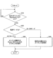
- FIG. 1 is an example of a flowchart illustrating an outline of an operation procedure of the guidance device.
- the guidance device detects that it has become unable to travel (Yes in S10).
- the state in which the vehicle cannot run is an engine stop (hereinafter referred to as an engine stall) for a vehicle powered by an internal combustion engine, a vehicle (EV) powered by an electric motor, or a vehicle powered by an electric motor (HV) Ready- It means turning off.
- an engine stop hereinafter referred to as an engine stall
- a vehicle powered by an internal combustion engine a vehicle (EV) powered by an electric motor
- HV electric motor
- the guidance device determines whether the power mode is the ACC mode or the IG-ON mode (S20). As will be described later, when the engine is stalled or Ready-OFF during driving, the power mode is either the ACC mode or the IG-ON mode.
- the guidance device provides “guidance for starting the engine or ready-ON” (S30).
- the guidance device provides “guidance for retracting the vehicle” (S40).
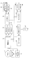
- FIG. 2 shows an example of a schematic configuration diagram of the guidance device.
- the guidance device is a power supply ECU (electronic ECU) connected via an in-vehicle network such as CAN (Controller Area Network). control unit) 14, meter ECU 18, engine ECU 24, smart ECU 22 and the like.
- the power ECU 14 includes an engine switch 11, a brake SW 12, a shift position sensor 13, an ACC relay 15, an IG1 relay 16, and an IG2 relay 17, a meter ECU 18 includes a meter panel 19, and an engine ECU 24 includes an engine (various types of engine control).
- Sensor and actuator) 25 and Ne sensor 26, and indoor antenna 23 is connected to smart ECU 22, respectively.
- Each ECU is only an example of the configuration of the guidance device, and may further include an ECU other than these ECUs, or may include only an ECU other than these ECUs.
- the engine switch 11 is a push button type momentary switch, and is given an urging force by an elastic body from the inside toward the initial position. That is, when an occupant (hereinafter, simply referred to as a driver) depresses the engine switch 11, the engine switch 11 is turned on, and when the driver releases the finger, the urging force of the built-in elastic body returns to the initial position and turns off. . Therefore, an on signal is output from the engine switch 11 to the power supply ECU 14 only while the driver is pressing the engine switch 11.
- the engine switch 11 has an indicator lamp 9.
- the indicator lamp 9 can notify whether or not the engine can be started by the lighting color. For example, if the engine can be started (the power mode can be any of OFF mode, ACC mode, and IG-ON mode). If the engine cannot be started, turn off if the power mode is OFF. In IG-ON mode, it lights up in amber.
- the brake SW is a switch that is turned on when the brake pedal is depressed from the initial position and turned off when the pedal force is reduced and returned to the initial position. Therefore, an on signal is output from the brake SW 12 to the power supply ECU 14 only while the driver depresses the brake pedal.
- the shift position sensor 13 is a sensor that detects the position (P, N, D, 1, 2, R, etc.) of the shift lever.
- the ACC relay 15 is a relay that turns on or off a power feeding line between a device called an accessory device (audio, navigation, room light, etc.) and a battery.
- the IG1 relay 16 is a relay that turns on or off a power feed line between a battery (such as a meter system or a wiper) that is not related to engine startup and a battery.
- the IG2 relay 17 is a relay that turns on or off a power supply line between a battery (such as an ignition coil and an injector) necessary for starting the engine and a battery.
- the meter panel 19 is provided with a speedometer, a tachometer, a fuel gauge, a water temperature gauge, a liquid crystal display unit 30 and the like.
- guidance is displayed on the liquid crystal display unit 30, but it may be displayed on a HUD (Head Up Display) or may be displayed on the liquid crystal display unit 30 of the center cluster.
- the guidance may be output from the speaker 21 by a voice message.
- the engine 25 is an internal combustion engine that mixes air and fuel for compression, combustion, expansion, and exhaust, and the type of fuel (gasoline, light oil, bioethanol, etc.), the number of cycles, the number of cylinders, and the system (reciprocating type, rotary engine) , Diesel engines that do not have injection, etc.).
- the Ne sensor 26 is also called a crank angle sensor, and is a sensor that notifies the engine ECU 24 of the engine speed.
- the smart ECU 22 periodically transmits a request radio wave from the indoor antenna 23, and the electronic key 27 depends on whether or not the ID included in the response key radio wave transmitted in response to the electronic key 27 matches a pre-registered ID. It is determined whether or not authentication is established. Since the power supply ECU 14 is notified when the authentication is established, the engine ECU 24 is allowed to start the engine.
- FIG. 3 is an example for explaining each power mode.
- the power mode includes an OFF mode, an ACC mode, and an IG-ON mode.
- Engine operating state” and “engine stopped state” are not power modes, but are described for explanation.
- the OFF mode is a power supply mode in which a minimum amount of power such as a function necessary for starting the engine, such as the power ECU 14 and the smart ECU 22, and a function for security are supplied to a minimum amount of equipment. Blocked.
- the ACC mode is a power supply mode in a state where the ACC relay 15 is turned on.
- the IG-ON mode is a power supply mode in which the ACC relay 15, the IG1 relay 16, and the IG2 relay 17 are turned on and power is supplied to all devices necessary for vehicle travel. More specifically, in the IG-ON mode, the power supply ECU 14 turns on the IG1 relay 16 and the IG2 relay 17 and turns off the ACC relay 15 to ensure electric power when starting the engine.
- the power supply ECU 14 Upon receiving the notification from the engine ECU, the power supply ECU 14 turns on the ACC relay 15, the IG1 relay 16, and the IG2 relay 17 (returns to the IG-ON mode).
- the “engine operating state” means that the engine is in a complete explosion state
- the “engine stopped state” means that the engine is stopped.
- the power supply ECU 14 When the engine switch 11 is detected to be pressed for a predetermined time or longer (for example, 3 seconds or longer) while the vehicle is running, the power supply ECU 14 turns off the IG1 relay 16 and the IG2 relay 17 while keeping the ACC relay 15 on. . Therefore, the power supply mode becomes the ACC mode (transition B in the figure). In this case as well, the engine cannot maintain its operating state and the engine stops. -Long press (during travel): IG-ON mode (engine operating state) ⁇ ACC mode
- the power supply ECU 14 changes the power supply mode The power mode remains the IG-ON mode (transition of A in the figure).
- the power mode changes from the IG-ON mode to the ACC mode during traveling only when the engine switch 11 is pressed for a predetermined time or longer while the vehicle is traveling. It is detected that the engine stalled by the user's operation.
- an operation in which the driver presses the engine switch 11 for a predetermined time or longer is referred to as an emergency stop operation.
- the emergency stop operation may be an operation in which the engine switch 11 is intermittently pressed a predetermined number of times (for example, three times) or more, and one or more emergency stop operations are determined in advance by the vehicle.
- the intermittent pressing means that the driver presses the engine switch 11 for a predetermined time or more within a predetermined time (for example, 1 to 3 seconds), for example.
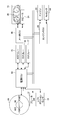
- FIG. 4 shows another example of a schematic configuration diagram of the guidance device.
- the guidance device of FIG. 4 does not have the smart ECU 22, and a key cylinder 28 is illustrated instead of the engine switch 11.
- the key cylinder 28 has rotational positions such as a LOCK position, an ACC position, an IG position, and a START position. When the driver inserts the mechanical key and rotates it to each rotational position of the cylinder, the key cylinder 28 outputs a Hi signal to the power supply ECU 14 according to the rotational position.
- the START position is biased to return to the IG position if the driver does not apply force to maintain this position.
- the shift position is other than P
- the driver can rotate the mechanical key only from the IG position to the ACC position. This is because the key cylinder 28 has a locking mechanism corresponding to the power mode.
- the rotational position of the mechanical key and the power supply mode correspond as follows.
- IG position: IG-ON mode In the OFF mode, the ACC relay 15, the IG1 relay 16, and the IG2 relay 17 are off, and in the ACC mode, only the ACC relay 15 is on. In the ON mode, the ACC relay 15, the IG1 relay 16, and the IG2 relay 17 are on.
- the power mode is set to the OFF mode when the mechanical key is rotated to the LOCK position regardless of whether the brake pedal is depressed. Since the power supply ECU 14 turns off the ACC relay 15, the IG1 relay 16, and the IG2 relay 17, the engine cannot maintain the operating state and the engine stops.
- -IG position-> LOCK position IG-ON mode (engine operation state)-> OFF mode
- the power mode is The ACC mode is set (the power supply ECU 14 turns off the IG1 relay 16 and the IG2 relay 17 while keeping the ACC relay 15 on).
- the power mode changes from the IG-ON mode to the ACC mode only when the mechanical key is rotated to the ACC position while the vehicle is traveling. It is detected that the engine stalled by the operation.
- FIG. 5 shows an example of a functional block diagram of the guidance device.
- the power supply ECU 14 includes an engine stall determination unit 31, a power supply mode determination unit 32, a power supply mode holding unit 34, and a guidance instruction unit 33. Since the power supply ECU 14 is a microcomputer including a CPU, RAM, ROM, input / output I / O, CAN controller, etc., the CPU executes a program stored in the ROM and cooperates with on-vehicle hardware. These functions can be realized.
- the engine stall determination unit 31 determines whether the vehicle has stalled while traveling.
- the engine stall has various causes such as a gas shortage or an emergency stop operation.
- the engine stall determination unit 31 determines that the engine stalled during traveling regardless of the cause. Note that “running” means that the vehicle speed is not less than zero (for example, greater than 0 km / h).
- the power supply mode is the IG-ON mode (engine operating state) as described above while the vehicle is running, power is supplied to all the devices mounted on the vehicle. For this reason, power supply ECU14 can acquire a signal from the various sensors mounted in the vehicle, and can determine that it is driving
- the engine stall determination unit 31 determines that the vehicle speed detected by the vehicle speed sensor is greater than or equal to a predetermined value. The engine stall is determined from the fact that the engine speed detected by the NE sensor 26 has decreased to an extent that it can be regarded as zero or zero. In addition, it may be determined that the engine is stalled by obtaining an engine stop signal from the engine ECU 24. Therefore, for example, the engine stall during traveling can be detected because the engine stall is performed within a predetermined time since the last vehicle speed was acquired. The engine stall determination unit 31 notifies the guidance instruction unit 33 that the engine stall has occurred during traveling.
- the power mode determination unit 32 determines the power mode according to the depression of the engine switch 11 (or the rotation position of the cylinder key), the shift position, the presence or absence of depression of the brake pedal, and the like. Store in the holding unit 34. As described above, due to engine stall (engine stop), the power mode is changed from the IG-ON mode to the OFF mode, or from the IG-ON mode to the ACC mode. This is only the case.
- the power mode holding unit 34 holds the current power mode as information such as a flag state.
- the guidance instruction unit 33 When the guidance instruction unit 33 obtains notification that the engine is stalled during traveling, the guidance instruction unit 33 requests the meter ECU 18 to display a guidance according to the current power supply mode of the power supply mode holding unit 34.
- the guidance instruction unit 33 When the power mode is the IG-ON mode, the meter ECU 18 is requested to display a message indicating that the vehicle should be stopped immediately.
- the meter ECU 18 displays a message such as “Evacuate the vehicle promptly on the road shoulder” on the liquid crystal display unit 30, for example.
- the power mode is the ACC mode
- the meter ECU 18 is requested to display a message for starting the engine.
- the meter ECU 18 “sets the shift position to N and press the engine switch 11”, and in the case of the mechanical key “set the shift position to N and turn the key to the START position”. And the like are displayed on the liquid crystal display unit 30.
- a message such as “The key has been operated to the ACC position” may be added.
- the meter ECU 18 not only to display but also to output a voice message from the speaker 21 to guide the engine starting method.
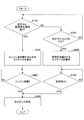
- FIG. 6 is an example of a flowchart for explaining an outline of the operation procedure of the guidance device.
- the procedure of FIG. 6 starts when the vehicle starts running, for example.
- the engine stall determination unit 31 detects that the engine is stalled while traveling (Yes in S100). If the engine stall is due to an emergency stop operation, the power supply mode transitions to the ACC mode. If the engine stall is other than that, the power supply mode remains in the IG-ON mode.
- the guidance instruction unit determines whether the power mode of the power mode holding unit 34 is the ACC mode or the IG-ON mode (S200).
- the guidance instruction unit 33 notifies the meter ECU 18 to display a guidance for starting the engine. Thereby, meter ECU18 displays the guidance for engine starting on the liquid crystal display part 30 (S300).
- the driver looks at the guidance and starts the engine. That is, in the case of the engine switch 11, the engine switch 11 is pressed, and in the case of a mechanical key, the key is rotated to the IG position.
- the brake pedal it is necessary to depress the brake pedal to start the engine, but there is a possibility that the driver may hesitate to depress the brake pedal to avoid a rear-end collision during inertial running. For this reason, in the following cases, when the power supply ECU 14 detects the depression of the engine switch 11 or the rotation of the mechanical key to the IG position, the ACC relay 15 and the IG1 relay 16 and the IG2 remain on regardless of the depression of the brake pedal.
- the relay 17 is turned on (transition from the ACC mode to the IG-ON mode) and the ST relay is turned on to rotate the start motor and start the engine.
- the brake pedal may be requested to be depressed (described in a message), or the engine start may be permitted only after the vehicle is stopped.
- the power supply mode is the ACC mode.
- the power supply ECU 14 can detect the engine speed and the vehicle speed.
- the guidance instruction unit 33 detects the start of the engine (S400), it requests the meter ECU 18 to erase the guidance. As a result, the meter ECU 18 erases the guidance (S500).
- the guidance may be deleted by detecting that the shift position is P, for example. This is because if the shift position is P, it can be estimated that the vehicle speed is zero or close to zero.
- the guidance instruction unit 33 notifies the meter ECU 18 to display guidance for retracting the vehicle. Thereby, meter ECU18 displays the guidance for retracting vehicles on liquid crystal display part 30 (S600).
- the power supply ECU 14 can detect a signal of the vehicle speed, and therefore the guidance instruction unit 33 requests the meter ECU 18 to erase the guidance when the vehicle speed becomes zero (S700), for example. As a result, the meter ECU 18 erases the guidance (S500).
- FIG. 7 is another example of a flowchart for explaining the outline of the operation procedure of the guidance device.
- the description of the same steps as in FIG. 6 is omitted.
- the engine stall determination unit determines whether an emergency stop operation has been performed during traveling (S110). Since the engine switch 11 and the key cylinder 28 are connected to the power supply ECU 14 and the emergency stop operation is detected separately from other operations, the fact that the emergency stop operation has been detected can be recorded.
- the engine stall determination unit uses the vehicle speed signal acquired last. Since vehicle speed information is used by many ECUs, it is acquired at relatively short time intervals. Therefore, the engine stall determination unit 31 can determine that the vehicle is traveling if the vehicle speed signal acquired last is equal to or greater than a predetermined value (for example, several tens of km / h).
- the meter ECU 18 displays guidance for starting the engine, and the driver visually checks the guidance to start the engine.
- the power supply ECU 14 detects that the engine switch 11 is pressed or the mechanical key is rotated to the IG position, and the ACC relay 15 remains on regardless of the depression of the brake pedal. 16 and IG2 relay 17 are turned on (transition from ACC mode to IG-ON mode) and ST relay is turned on to rotate the start motor and start the engine.
- an engine stall determination part determines whether the engine stalled during driving
- FIG. 8 shows an example of a schematic configuration diagram of the guidance device of the present embodiment.
- the guidance apparatus of FIG. 8 is a form corresponding to an HV vehicle or an EV vehicle.
- an HV vehicle will be described as an example, but the present invention can also be suitably applied to an EV vehicle.
- the HV-ECU 29 determines a required torque to be output to the drive shaft with reference to the map based on the accelerator opening and the vehicle speed.
- a torque command value for distributing the required torque to the engine and the motor is determined so that the SOC of the battery is within an efficient range and the engine is operated efficiently.
- Each torque command value is transmitted to the engine ECU 24 and the motor ECU, and at least one of the engine and the motor drives the vehicle.
- FIG. 9 is an example of a diagram illustrating each state of the power supply mode.
- power modes include OFF mode, ACC mode, and IG-ON mode.
- IG-ON mode is IG-ON mode (Ready-OFF state) and IG-ON mode (Ready-ON state) There are two).
- the IG-ON mode is a power supply mode in which the HV-ECU 29 is normally started and the vehicle can run by engine running or motor running.
- the HV-ECU 29 In the IG-ON mode (Ready-OFF state), the HV-ECU 29 is not operating normally (for example, the ACC relay 15, the IG1 relay 16, and the IG2 relay 17 are on, but the HV-ECU 29 is Ready-ON). Signal is not output).
- the power mode can be in a Ready-ON state by pressing the engine switch 11 once from any power mode.
- the reason that it can be “becomes possible” is because there are rare cases in which the Ready-ON state is not obtained.
- the power supply ECU 14 turns on the ACC relay 15, the IG1 relay 16, and the IG2 relay 17 and outputs an activation signal to the HV-ECU 29.
- the HV-ECU 29 reads the program, executes initial processing and self-diagnosis, and determines whether or not it is in a startable state.
- a Ready-ON signal is output to power supply ECU etc.
- the power supply ECU 14 receives the Ready-ON signal and enters the Ready-ON state.
- ⁇ OFF mode ⁇ IG-ON mode (Ready-ON state)
- ACC mode ⁇ IG-ON mode (Ready-ON state)
- IG-ON mode Ready-OFF state
- IG-ON mode Ready-ON state
- the HV-ECU 29 starts the engine when the engine is to be started in the Ready-ON state. Therefore, the power supply mode becomes the IG-ON mode (Ready-ON state) and the engine operating state, or the IG-ON mode (Ready-ON state) and the engine stopped state.
- the power mode is set to the OFF mode when the engine switch 11 is pressed once regardless of whether the brake pedal is depressed. Since the power supply ECU 14 turns off the ACC relay 15, the IG1 relay 16, and the IG2 relay 17, the HV-ECU 29 that stops supplying power stops the execution of the program and the output of the Ready-ON signal after executing the post-processing. (Hereafter referred to simply as Ready-OFF). When the power supply ECU 14 cannot acquire the Ready-ON signal, it enters the OFF mode. Whether the engine is operating does not affect the power mode. -IG-ON mode (Ready-ON state)-> OFF mode Note that when the shift position is other than P, even when the vehicle is stopped, the power supply mode is only the ACC mode when the engine switch 11 is pressed once. Don't be.
- the power supply ECU 14 changes the power supply mode to the ACC mode (transition B in the figure).
- the ACC relay 15 is left and the IG1 relay 16 and the IG2 relay 17 are turned off, so that the HV-ECU 29 in which power is not supplied stops the execution of the program and the output of the Ready-ON signal after executing the post-processing. Therefore, power supply ECU14 will be in ACC mode.
- the method for determining that the vehicle is running is the same as in the first embodiment.
- the power supply mode transitions from the IG-ON mode (Ready-ON state) to the ACC mode only when the engine switch 11 is pressed for a predetermined time or more while the vehicle is running, so use this.
- the HV-ECU 29 is Ready-OFF by the driver's operation.
- FIG. 10 shows an example of a functional block diagram of the guidance device. 10, the description of the same part as in FIG. 5 is omitted.
- the Ready-OFF determination unit 34 determines whether or not the HV-ECU 29 stops outputting the Ready-ON signal while the vehicle is traveling (whether or not it is Ready-OFF).
- the case where Ready-OFF is performed during traveling is a case where an emergency stop operation is performed or an external action is applied to the vehicle or some ECU.
- the Ready-OFF determination unit 34 determines that the vehicle has been Ready-OFF during traveling regardless of the cause.
- the method for determining that the vehicle is running is the same as in the first embodiment.
- the Ready-OFF is determined because the HV-ECU 29 stops outputting the Ready-ON signal.
- the guidance instruction unit 33 determines the power mode when Ready-OFF. As described above, the power supply mode is changed from IG-ON mode (Ready-ON state) to IG-ON mode (Ready-OFF state) or IG-ON mode (Ready-ON state) by Ready-OFF of HV-ECU 29. ) To ACC mode, but the transition to ACC mode during traveling is only in the case of an emergency stop operation.
- the guidance instruction unit 33 When the guidance instruction unit 33 receives a notification that the vehicle is Ready-OFF during traveling, the guidance instruction unit 33 requests the meter ECU 18 to display a guidance according to the current power mode of the power mode holding unit 34.
- the guidance instruction unit 33 When the power mode is the IG-ON mode (Ready-OFF state), the meter ECU 18 is requested to display a message that the vehicle should be stopped immediately.
- the power supply mode is the ACC mode, the meter ECU 18 is requested to display a message for Ready-ON.
- FIG. 11 is an example of a flowchart for explaining the outline of the operation procedure of the guidance device.
- the same description as in FIG. 6 is omitted.
- the Ready-OFF determination unit 34 detects that the vehicle is Ready-OFF while traveling (Yes in S120). If Ready-OFF is due to an emergency stop operation, the power supply mode transitions to the ACC mode, and if it is other than that, the power supply mode transitions to the IG-ON mode (Ready-OFF state).
- the guidance instruction unit 33 determines whether the power mode of the power mode holding unit 34 is the ACC mode or the IG-ON mode (Ready-OFF state) (S200).
- the guidance instruction unit 33 notifies the meter ECU 18 to display guidance for Ready-ON. Thereby, meter ECU18 displays guidance for Ready-ON on liquid crystal display part 30 (S310). A message such as “Please set the shift position to N and press the engine switch 11” is displayed as guidance.
- the driver visually checks the guidance and presses the engine switch 11.
- the power supply ECU 14 detects that the engine switch 11 is pressed in the following cases, the power supply mode is changed from the ACC mode to the IG-ON mode (Ready-ON state) regardless of the depression of the brake pedal, and the start signal is sent to the HV- By outputting to the ECU 29, the HV-ECU 29 outputs a Ready-ON signal.
- the power supply mode is ACC mode
- the guidance for Ready-ON is displayed
- the IG-ON mode Ready-ON state
- the guidance instruction unit 33 requests the meter ECU 18 to erase the guidance based on the Ready-ON signal.
- the meter ECU 18 erases the guidance (S500).
- the processing when the power mode is the IG-ON mode (Ready-OFF state) is the same as that in the first embodiment.
- the content of guidance display may be switched by detecting “emergency stop operation during travel” as in the first embodiment.
Landscapes
- Engineering & Computer Science (AREA)
- Automation & Control Theory (AREA)
- Mechanical Engineering (AREA)
- Chemical & Material Sciences (AREA)
- Combustion & Propulsion (AREA)
- General Engineering & Computer Science (AREA)
- Human Computer Interaction (AREA)
- Transportation (AREA)
- Control Of Vehicle Engines Or Engines For Specific Uses (AREA)
- Combined Controls Of Internal Combustion Engines (AREA)
Abstract
Description
14 電源ECU
15 ACCリレー
16 IG1リレー
17 IG2リレー
18 メータECU
19 メータパネル
21 スピーカ
24 エンジンECU
25 エンジン
27 電子キー
30 液晶表示部
図1は、ガイダンス装置の動作手順の概略を説明するフローチャート図の一例である。走行中、ガイダンス装置は走行できない状態になったことを検出する(S10のYes)。走行できない状態とは、内燃機関を動力とする車両はエンジンストップ(以下、エンストという)、電気モータを動力とする車両(EV)又は電気モータを一部の動力とする車両(HV)はReady-OFFすることをいう。
control unit)14、メータECU18、エンジンECU24、及び、スマートECU22等を有する。電源ECU14にはエンジンスイッチ11、ブレーキSW12、シフトポジションセンサ13、ACCリレー15、IG1リレー16及びIG2リレー17が、メータECU18にはメータパネル19が、エンジンECU24にはエンジン(エンジン制御用の各種のセンサやアクチュエータ)25とNeセンサ26が、スマートECU22には室内アンテナ23が、それぞれ接続されている。なお、各ECUはガイダンス装置の構成例に過ぎず、これらのECU以外のECUをさらに有していてもよいし、これらのECU以外のECUのみで構成されていてもよい。
ブレーキペダルが踏み込まれていない場合、電源モードは、エンジンスイッチ11が押下される毎に遷移する。
1回目:OFFモード→ACCモード
2回目:ACCモード→IG-ONモード
3回目:IG-ONモード→OFFモード
<エンジン始動される際の電源モードの遷移>
ブレーキペダルが踏み込まれている場合(シフトポジションはP又はNであることが推奨されている)、電源モードは、どの電源モードからもエンジンスイッチ11が1回押下されることで、IGオン状態になる。また、電源ECU14は不図示のSTリレーをオンにすることで、スタートモータを回転させエンジンを始動する。
・OFFモード→IG-ONモード
・ACCモード→IG-ONモード
エンジン始動が成功すれば、電源モードはIG-ONモードかつエンジン作動状態となる。
シフトポジションがPかつ車両停止中の場合、ブレーキペダルの踏み込みの有無に関係なく、電源モードは、エンジンスイッチ11が1回押下されることでOFFモードになる。電源ECU14はこの条件を満たすとACCリレー15、IG1リレー16、及び、IG2リレー17をオフにするので、エンジンは作動状態を維持できなくなりエンジンが停止する。
・IG-ONモード(エンジン作動状態)→OFFモード
なお、シフトポジションがP以外の場合、車両停止中の場合でも、電源モードは、エンジンスイッチ11が1回押下されることでACCモードにしかならない(電源ECU14はシフトポジションがP以外の場合、ACCリレー15をオンのまま、IG1リレー16とIG2リレー17をオフにする)。この場合もエンジンは作動状態を維持できなくなりエンジンが停止する。
・長押し(走行中):IG-ONモード(エンジン作動状態)→ACCモード
これに対し、車両が走行中、運転者が緊急停止操作を行わずにエンストした場合、電源ECU14は電源モードを遷移させていないので、電源モードはIG-ONモードのままである(図のAの遷移)。
図1では、エンジンスイッチ11の押下により電源モードが切り替わるガイダンス装置について説明したが、メカニカルキーの操作により電源モードが切り替わる場合も同様にガイダンス装置を構成できる。
LOCK位置:OFFモード
ACC位置:ACCモード
IG位置:IG-ONモード
OFFモードではACCリレー15、IG1リレー16及びIG2リレー17はオフであり、ACCモードではACCリレー15のみがオンであり、IG-ONモードではACCリレー15、IG1リレー16及びIG2リレー17がオンである。
そして、運転者がブレーキペダルを踏み込んだ状態で、メカニカルキーをSTART位置まで回転させると、その間だけ、電源ECU14はACCリレー15とIG2リレー17をオフにしてIG1リレー16のみをオンにすると共に、STリレーをオンにする。STリレーをオンにすることで、スタートモータが回転してエンジンが始動する。付勢力によりメカニカルキーがSTART位置からIG位置に戻された際、エンジンが完爆していれば、IG-ONモード(エンジン作動状態)となる。
・IG位置→START位置→IG位置:IG-ONモード(エンジン作動状態)
IG位置は必ず経由するのでこのように記述したが、LOCK位置及びACC位置からもエンジン始動できる。
シフトポジションがPかつ車両停止中の場合、ブレーキペダルの踏み込みの有無に関係なく、電源モードは、メカニカルキーがLOCK位置まで回転されるとOFFモードになる。電源ECU14はACCリレー15、IG1リレー16、及び、IG2リレー17をオフにするので、エンジンは作動状態を維持できなくなりエンジンが停止する。
・IG位置→LOCK位置:IG-ONモード(エンジン作動状態)→OFFモード
なお、上記のようにシフトポジションがP以外の場合、運転者はメカニカルキーをACC位置までしか回転できないので、電源モードはACCモードになる(電源ECU14はACCリレー15をオンのまま、IG1リレー16とIG2リレー17をオフにする。)。この場合もエンジンは作動状態を維持できなくなりエンジンが停止する。
・IG位置→ACC位置:IG-ONモード(エンジン作動状態)→ACCモード
そして、車両が走行中の場合も(シフトポジションはD等のP以外であるため、又は、走行中は係止機構が働くため)、メカニカルキーはACC位置までしか回転されないので、電源モードはACCモードになる。メカニカルキーの場合、この走行中のIG位置→ACC位置の操作が緊急停止操作となる。電源ECU14はACCリレー15をオンのまま、IG1リレー16とIG2リレー17をオフにする。この場合もエンジンは作動状態を維持できなくなりエンジンが停止する。
・IG位置→ACC位置(走行中):IG-ONモード(エンジン作動状態)→ACCモード
これに対し、運転者が緊急停止操作を行わずにエンストした場合、電源ECU14は電源モードを遷移させていないので、電源モードはIG-ONモードのままである。
図5は、ガイダンス装置の機能ブロック図の一例を示す。電源ECU14は、エンスト判定部31、電源モード判定部32、電源モード保持部34、及び、ガイダンス指示部33を有する。電源ECU14は、CPU、RAM、ROM、入出力I/O、CANコントローラ等を備えたマイコンであるので、CPUがROMに記憶されたプログラムを実行すること及び車載されたハードウェアと協働することでこれらの機能が実現される。
・電源モードがIG-ONモードの場合、車両を速やかに停止すべき旨のメッセージを表示するようメータECU18に要求する。
・電源モードがACCモードの場合、エンジンを始動するためのメッセージを表示するようメータECU18に要求する。
図6は、ガイダンス装置の動作手順の概略を説明するフローチャート図の一例である。図6の手順は、例えば、車両が走行を開始するとスタートする。
・走行中のエンストが検出され、かつ、電源モードがACCモードであった場合
・エンジン始動のためのガイダンスを表示した場合
IG-ONモードになると、電源ECU14はエンジン回転数や車速を検出できるので、ガイダンス指示部33はエンジンの始動を検出すると(S400)、メータECU18にガイダンスの消去を要求する。これにより、メータECU18はガイダンスを消去する(S500)。エンジンの始動を検出した場合以外に、例えばシフトポジションがPになったことを検出して、ガイダンスを消去してもよい。シフトポジションがPになれば車速がゼロ又はゼロ近くであると推定できるためである。
図6では「走行中のエンストが検出され、かつ、電源モードがACCモードであった場合」に、エンジン始動のガイダンスを表示したが、緊急停止操作を検出してエンジン始動のガイダンスを表示してもよい。
・走行中に緊急停止操作が検出された場合(操作が記録されている場合)
・エンジン始動のためのガイダンスを表示した場合
なお、走行中に緊急停止操作が行われない場合(S110のNo)、エンスト判定部は走行中にエンストしたか否かを判定する(S120)。この場合のエンストは、緊急停止操作以外によるものなので、車両を退避するためのガイダンスが表示される(S600)。以降の処理は図6と同様なので説明を省略する。
ブレーキペダルが踏み込まれていない場合、電源モードは、エンジンスイッチ11が押下される毎に遷移する。
1回目:OFFモード→ACCモード
2回目:ACCモード→IG-ONモード(Ready-OFF状態)
3回目:IG-ONモード(Ready-OFF状態)→OFFモード
すなわち、ブレーキペダルが踏み込まれていない場合、電源モードはIG-ONモード(Ready-ON状態)にはならない。
ブレーキペダルが踏み込まれている場合、電源モードは、どの電源モードからもエンジンスイッチ11が1回押下されることで、Ready-ON状態になりうる。“なりうる”としたのはReady-ON状態にならない場合がまれにあるためである。電源ECU14は、ブレーキペダルが踏み込まれた状態でエンジンスイッチ11が1回押下されると、ACCリレー15、IG1リレー16及びIG2リレー17をオンにすると共に、HV-ECU29に起動信号を出力する。HV-ECU29は、リセット後、プログラムを読み出して初期処理や自己診断を実行し、起動可能な状態であるか否かを判定する。そして、起動可能である場合にのみ、Ready-ON信号を電源ECU等に出力する。電源ECU14は、Ready-ON信号を受信してReady-ON状態になる。
・OFFモード→IG-ONモード(Ready-ON状態)
・ACCモード→IG-ONモード(Ready-ON状態)
・IG-ONモード(Ready-OFF状態)→IG-ONモード(Ready-ON状態)
HV-ECU29は、Ready-ON状態において、エンジンを始動すべき状況になるとエンジンを始動する。よって電源モードはIG-ONモード(Ready-ON状態)かつエンジン作動状態、又は、IG-ONモード(Ready-ON状態)かつエンジン停止状態となる。
シフトポジションがPかつ車両停止中の場合、ブレーキペダルの踏み込みの有無に関係なく、電源モードは、エンジンスイッチ11が1回押下されることでOFFモードになる。電源ECU14はACCリレー15、IG1リレー16、及び、IG2リレー17をオフにするので、電力が供給されなくなるHV-ECU29は後処理を実行後、プログラムの実行やReady-ON信号の出力を停止する(以下、単にReady-OFFしたという)。電源ECU14はReady-ON信号を取得できなくなるとOFFモードになる。エンジン作動中か否かは電源モードに影響しない。
・IG-ONモード(Ready-ON状態)→OFFモード
なお、シフトポジションがP以外の場合、車両停止中の場合でも、電源モードは、エンジンスイッチ11が1回押下されることでACCモードにしかならない。
長押し(走行中):IG-ONモード(Ready-ON状態)→ACCモード
これに対し、運転者が緊急停止操作を行わずにHV-ECU29がReady-ON信号を出力しなくなった場合、電源ECU14はACCリレー15、IG1リレー16及びIG2リレー17をオンにしたままにする。このため、電源モードはIG-ONモード(Ready-ON状態)モードからIG-ONモード(Ready-OFF状態)になる(図のAの遷移)。
図10は、ガイダンス装置の機能ブロック図の一例を示す。図10において図5と同一部の説明は省略する。
・電源モードがIG-ONモード(Ready-OFF状態)の場合、車両を速やかに停止すべき旨のメッセージを表示するようメータECU18に要求する。
・電源モードがACCモードの場合、Ready-ONするためのメッセージを表示するようメータECU18に要求する。
図11は、ガイダンス装置の動作手順の概略を説明するフローチャート図の一例である。図11において図6と同様の説明は省略する。まず、Ready-OFF判定部34は、車両が走行中、Ready-OFFしたことを検出する(S120のYes)。Ready-OFFが、緊急停止操作によるものであれば電源モードはACCモードに遷移し、それ以外によるものであれば電源モードはIG-ONモード(Ready-OFF状態)に遷移する。
・走行中のReady-OFFが検出され、かつ、電源モードがACCモードであった場合
・Ready-ONのためのガイダンスを表示した場合
IG-ONモード(Ready-ON状態)になると(S410のYes)、ガイダンス指示部33はReady-ON信号に基づき、メータECU18にガイダンスの消去を要求する。これにより、メータECU18はガイダンスを消去する(S500)。なお、電源モードがIG-ONモード(Ready-OFF状態)であった場合の処理は実施例1と同様である。
Claims (5)
- 車両操作方法を教示するガイダンス装置であって、
エンジン始動若しくは停止の操作を受け付ける、又は、少なくとも電動機を含む走行システムの始動若しくは停止の操作を受け付ける操作受付手段と、
前記操作受付手段が受け付けた操作及び車両状態に応じて定められた電源モードに制御する電源制御手段と、
走行中のエンジン停止又は走行システムの停止を検出する停止検出手段と、
電源モードに基づきエンジン停止又は走行システムの停止の原因が人為的操作によるものか否かを判定する停止要因判定手段と、
人為的操作によるものか否かに応じてガイダンス内容を変更するガイダンス手段と、を有するガイダンス装置。 - 電源モードが走行に使用されない第1の機器を電源供給先とする電源モードの場合、前記ガイダンス手段はエンジンを始動させるためのガイダンスを教示し、
電源モードが走行に使用される第2の機器を電源供給先とする電源モードの場合、前記ガイダンス手段は車両を退避させるためのガイダンスを教示する、
ことを特徴とする請求項1記載のガイダンス装置。 - 前記ガイダンス手段は、メッセージを表示装置に表示することでガイダンスを教示する、ことを特徴とする請求項1又は2記載のガイダンス装置。
- 前記ガイダンス手段は、メッセージを音声出力することでガイダンスを教示する、ことを特徴とする請求項1又は2記載のガイダンス装置。
- 車両操作方法を教示するガイダンス装置のガイダンス方法であって、
エンジン始動若しくは停止の操作を受け付ける、又は、少なくとも電動機を含む走行システムの始動若しくは停止の操作を受け付ける操作受付ステップと、
前記操作受付ステップにより受け付けられた操作及び車両状態に応じて定められた電源モードに制御する電源制御ステップと、
走行中のエンジン停止又は走行システムの停止を検出する停止検出ステップと、
電源モードに基づきエンジン停止又は走行システムの停止の原因が人為的操作によるものか否かを判定する停止要因判定ステップと、
人為的操作によるものか否かに応じてガイダンス内容を変更するガイダンスステップと、
を有するガイダンス方法。
Priority Applications (4)
| Application Number | Priority Date | Filing Date | Title |
|---|---|---|---|
| US14/125,440 US9199587B2 (en) | 2011-06-14 | 2011-06-14 | Guidance device, guidance method |
| PCT/JP2011/063598 WO2012172644A1 (ja) | 2011-06-14 | 2011-06-14 | ガイダンス装置、ガイダンス方法 |
| JP2013520355A JP5594432B2 (ja) | 2011-06-14 | 2011-06-14 | ガイダンス装置、ガイダンス方法 |
| EP11867935.6A EP2722236B1 (en) | 2011-06-14 | 2011-06-14 | Guidance device and guidance method |
Applications Claiming Priority (1)
| Application Number | Priority Date | Filing Date | Title |
|---|---|---|---|
| PCT/JP2011/063598 WO2012172644A1 (ja) | 2011-06-14 | 2011-06-14 | ガイダンス装置、ガイダンス方法 |
Publications (1)
| Publication Number | Publication Date |
|---|---|
| WO2012172644A1 true WO2012172644A1 (ja) | 2012-12-20 |
Family
ID=47356671
Family Applications (1)
| Application Number | Title | Priority Date | Filing Date |
|---|---|---|---|
| PCT/JP2011/063598 Ceased WO2012172644A1 (ja) | 2011-06-14 | 2011-06-14 | ガイダンス装置、ガイダンス方法 |
Country Status (4)
| Country | Link |
|---|---|
| US (1) | US9199587B2 (ja) |
| EP (1) | EP2722236B1 (ja) |
| JP (1) | JP5594432B2 (ja) |
| WO (1) | WO2012172644A1 (ja) |
Cited By (3)
| Publication number | Priority date | Publication date | Assignee | Title |
|---|---|---|---|---|
| CN105264309A (zh) * | 2013-04-01 | 2016-01-20 | 冷王公司 | 阻止非法修改发动机控制软件或控制系统的系统和方法 |
| CN111619481A (zh) * | 2020-06-05 | 2020-09-04 | 江铃汽车股份有限公司 | 车辆档位控制系统、方法和车辆 |
| KR20220028121A (ko) * | 2019-08-06 | 2022-03-08 | 비테스코 테크놀로지스 저머니 게엠베하 | 단일 인쇄 회로 보드에 갈바닉 절연된 공급 전압을 갖는 차량용 전자 제어 유닛 |
Families Citing this family (5)
| Publication number | Priority date | Publication date | Assignee | Title |
|---|---|---|---|---|
| JP5642730B2 (ja) * | 2012-04-25 | 2014-12-17 | トヨタ自動車株式会社 | 車両および車両の制御方法 |
| JP5767157B2 (ja) | 2012-04-25 | 2015-08-19 | トヨタ自動車株式会社 | 車両および車両の制御方法 |
| JP6126171B2 (ja) * | 2015-07-10 | 2017-05-10 | 本田技研工業株式会社 | 緊急時車両制御装置 |
| SE542472C2 (en) * | 2016-06-22 | 2020-05-19 | Scania Cv Ab | Method for controlling an internal combustion engine experienceing uncontrolled behavior in a vehicle |
| EP4095006A1 (en) * | 2021-05-26 | 2022-11-30 | Taiga Motors Inc. | Vehicle activation systems and methods for electric vehicles |
Citations (3)
| Publication number | Priority date | Publication date | Assignee | Title |
|---|---|---|---|---|
| JPH11278091A (ja) * | 1998-03-30 | 1999-10-12 | Toyota Motor Corp | エンジン始動装置 |
| JP2003089332A (ja) | 2001-09-17 | 2003-03-25 | Toshiba Corp | 車両ガイダンス装置 |
| JP2009068587A (ja) * | 2007-09-12 | 2009-04-02 | Toyota Motor Corp | 車両用制御装置 |
Family Cites Families (33)
| Publication number | Priority date | Publication date | Assignee | Title |
|---|---|---|---|---|
| US3788422A (en) * | 1972-10-27 | 1974-01-29 | Gmc Co | Anti-theft system including a pushbutton electronic combination ignition lock and transmission shift control |
| US4328547A (en) * | 1978-02-27 | 1982-05-04 | The Bendix Corporation | Failure system for internal combustion engine |
| JPS5818524A (ja) * | 1981-07-27 | 1983-02-03 | Toyota Motor Corp | エンジン自動停止始動装置 |
| JPS58162743A (ja) * | 1982-03-23 | 1983-09-27 | Nissan Motor Co Ltd | 自動車のエンジン停止始動制御装置 |
| IT1178969B (it) * | 1984-06-15 | 1987-09-16 | Fiat Auto Spa | Apparato di rivviamento automatico del motore di un autoveicolo dopo una frenata brusca in condizione discarsa aderenza |
| JPS62142862A (ja) * | 1985-12-17 | 1987-06-26 | Yamaha Motor Co Ltd | エンジン停止スイツチの状態表示装置 |
| US4878042A (en) * | 1988-06-14 | 1989-10-31 | J. Michael Eggiman | Apparatus for flashing vehicle lights to warn of engine stall |
| JPH07229437A (ja) * | 1994-02-18 | 1995-08-29 | Nippondenso Co Ltd | 内燃機関の燃料噴射制御装置 |
| GB2300705A (en) * | 1995-05-10 | 1996-11-13 | Christopher Lawrence Baigent | An automatic hazard warning light activation system for motor vehicles |
| FR2764337B1 (fr) * | 1997-06-05 | 1999-07-16 | Jean Bernard Froidefond | Dispositif d'arret automatique d'un moteur thermique tournant au ralenti lors d'un stationnement prolonge d'un vehicule |
| JP3836275B2 (ja) * | 1999-08-16 | 2006-10-25 | 本田技研工業株式会社 | エンジン自動始動停止制御装置 |
| DE19941973C5 (de) * | 1999-09-03 | 2012-05-16 | Volkswagen Ag | Verfahren und Vorrichtung zur aktiven Hilfestellung eines Kraftfahrzeugführers in einem Kraftfahrzeug |
| JP2002187479A (ja) * | 2000-12-20 | 2002-07-02 | Yazaki Corp | エンジンストップ警告装置 |
| JP3633531B2 (ja) * | 2001-08-28 | 2005-03-30 | トヨタ自動車株式会社 | 内燃機関の停止・始動制御装置 |
| DE10211464A1 (de) * | 2002-03-15 | 2003-09-25 | Daimler Chrysler Ag | Vorrichtung zur Anzeige einer Start/Stopp-Funktion |
| EP1769985B1 (en) * | 2002-04-24 | 2011-10-05 | Kabushiki Kaisha Tokai Rika Denki Seisakusho | Vehicle engine starting apparatus |
| KR20040065870A (ko) * | 2003-01-16 | 2004-07-23 | 현대모비스 주식회사 | 차량의 엔진꺼짐 경고시스템 및 그 경고방법 |
| JP2005256631A (ja) * | 2004-03-09 | 2005-09-22 | Keihin Corp | エンジン停止報知装置 |
| US7091839B2 (en) * | 2004-03-09 | 2006-08-15 | Ford Global Technologies, Llc | Indicator for a hybrid electric vehicle |
| JP4121984B2 (ja) * | 2004-07-15 | 2008-07-23 | 株式会社ケーヒン | アイドル停止制御装置 |
| JP2006077592A (ja) * | 2004-09-07 | 2006-03-23 | Denso Corp | 車両のエンジン始動システム |
| KR20060067558A (ko) * | 2004-12-15 | 2006-06-20 | 주식회사 현대오토넷 | 시동의 꺼짐을 알리는 차량 |
| JP4435015B2 (ja) | 2005-04-14 | 2010-03-17 | パナソニック株式会社 | エンジン始動システム |
| JP2007023919A (ja) | 2005-07-19 | 2007-02-01 | Denso Corp | エンジン始動制御システム |
| JP4474367B2 (ja) * | 2006-01-24 | 2010-06-02 | トヨタ自動車株式会社 | 動力出力装置や駆動装置およびその制御方法並びに車両 |
| JP4578420B2 (ja) * | 2006-02-28 | 2010-11-10 | 富士通テン株式会社 | バッテリ上り防止装置 |
| JP4550760B2 (ja) * | 2006-03-29 | 2010-09-22 | 古河電気工業株式会社 | エンジン始動・停止制御装置 |
| DE102007030524B4 (de) * | 2007-06-16 | 2019-04-11 | Bayerische Motoren Werke Aktiengesellschaft | Anzeigevorrichtung für ein Fahrzeug |
| JP4811360B2 (ja) * | 2007-06-21 | 2011-11-09 | マツダ株式会社 | 車両用制御装置 |
| JP4492668B2 (ja) * | 2007-10-23 | 2010-06-30 | トヨタ自動車株式会社 | 車両用電源システム |
| JP2010065573A (ja) * | 2008-09-09 | 2010-03-25 | Honda Motor Co Ltd | 車両の制御装置 |
| DE102008052839B4 (de) * | 2008-10-22 | 2017-02-09 | Robert Bosch Gmbh | Steuervorrichtung für ein Fahrzeug und Verfahren zum Betreiben eines Fahrzeugmotors |
| JP4924849B2 (ja) * | 2009-07-31 | 2012-04-25 | 株式会社デンソー | 車両のエンジン始動システム |
-
2011
- 2011-06-14 US US14/125,440 patent/US9199587B2/en not_active Expired - Fee Related
- 2011-06-14 EP EP11867935.6A patent/EP2722236B1/en not_active Not-in-force
- 2011-06-14 JP JP2013520355A patent/JP5594432B2/ja not_active Expired - Fee Related
- 2011-06-14 WO PCT/JP2011/063598 patent/WO2012172644A1/ja not_active Ceased
Patent Citations (3)
| Publication number | Priority date | Publication date | Assignee | Title |
|---|---|---|---|---|
| JPH11278091A (ja) * | 1998-03-30 | 1999-10-12 | Toyota Motor Corp | エンジン始動装置 |
| JP2003089332A (ja) | 2001-09-17 | 2003-03-25 | Toshiba Corp | 車両ガイダンス装置 |
| JP2009068587A (ja) * | 2007-09-12 | 2009-04-02 | Toyota Motor Corp | 車両用制御装置 |
Non-Patent Citations (1)
| Title |
|---|
| See also references of EP2722236A4 |
Cited By (10)
| Publication number | Priority date | Publication date | Assignee | Title |
|---|---|---|---|---|
| CN105264309A (zh) * | 2013-04-01 | 2016-01-20 | 冷王公司 | 阻止非法修改发动机控制软件或控制系统的系统和方法 |
| EP2981773A4 (en) * | 2013-04-01 | 2017-01-25 | Thermo King Corporation | System and method for preventing unauthorized modification to engine control software or an engine control system |
| US9803610B2 (en) | 2013-04-01 | 2017-10-31 | Thermo King Corporation | System and method for preventing unauthorized modification to engine control software or an engine control system |
| US9920733B2 (en) | 2013-04-01 | 2018-03-20 | Thermo King Corporation | System and method for preventing unauthorized modification to engine control software or an engine control system |
| KR20220028121A (ko) * | 2019-08-06 | 2022-03-08 | 비테스코 테크놀로지스 저머니 게엠베하 | 단일 인쇄 회로 보드에 갈바닉 절연된 공급 전압을 갖는 차량용 전자 제어 유닛 |
| JP2022543443A (ja) * | 2019-08-06 | 2022-10-12 | ヴィテスコ テクノロジーズ ジャーマニー ゲー・エム・ベー・ハー | 単一のプリント回路基板上にガルバニック絶縁された給電電圧を有する車両用の電子制御ユニット |
| JP7472268B2 (ja) | 2019-08-06 | 2024-04-22 | ヴィテスコ テクノロジーズ ジャーマニー ゲー・エム・ベー・ハー | 単一のプリント回路基板上にガルバニック絶縁された給電電圧を有する車両用の電子制御ユニット |
| KR102742584B1 (ko) * | 2019-08-06 | 2024-12-12 | 비테스코 테크놀로지스 저머니 게엠베하 | 단일 인쇄 회로 보드에 갈바닉 절연된 공급 전압을 갖는 차량용 전자 제어 유닛 |
| US12391145B2 (en) | 2019-08-06 | 2025-08-19 | Vitesco Technologies Germany Gmbh | Electronic control unit for a vehicle with galvanically isolated supply voltages on a single printed circuit board |
| CN111619481A (zh) * | 2020-06-05 | 2020-09-04 | 江铃汽车股份有限公司 | 车辆档位控制系统、方法和车辆 |
Also Published As
| Publication number | Publication date |
|---|---|
| US9199587B2 (en) | 2015-12-01 |
| EP2722236A4 (en) | 2015-04-29 |
| EP2722236A1 (en) | 2014-04-23 |
| JP5594432B2 (ja) | 2014-09-24 |
| US20140107902A1 (en) | 2014-04-17 |
| JPWO2012172644A1 (ja) | 2015-02-23 |
| EP2722236B1 (en) | 2016-03-09 |
Similar Documents
| Publication | Publication Date | Title |
|---|---|---|
| JP5594432B2 (ja) | ガイダンス装置、ガイダンス方法 | |
| JP5540804B2 (ja) | アイドルストップ制御装置 | |
| JP2009197977A (ja) | シフトレンジ切替制御装置 | |
| US10131275B2 (en) | Motive power operation guidance apparatus | |
| CN102782304B (zh) | 特别是在发动机的发动机罩打开时用于控制车辆的发动机的起动和停止车辆控制设备及方法 | |
| CN105620463B (zh) | 车辆控制系统和使用车辆控制系统的方法 | |
| US20130096769A1 (en) | Electronic control unit | |
| CN114261367A (zh) | 车辆控制系统及车辆 | |
| JP2016199254A (ja) | 車両制御装置 | |
| JP2014151808A (ja) | 電源ポジション切替装置 | |
| KR101669668B1 (ko) | 차량 가동 정보를 이용한 공회전 제한 장치 및 방법 | |
| US9296394B2 (en) | Engine non-stop warning apparatus | |
| US7964986B2 (en) | Drive control apparatus, system and method | |
| JP5426845B2 (ja) | ハイブリッド電気自動車における、運転者への警告方法 | |
| JP2011089506A (ja) | エンジン制御装置 | |
| JP4888294B2 (ja) | 車両用制御装置 | |
| US20090178869A1 (en) | Cruise control system having verification and/or notification features | |
| JP2012136950A (ja) | 車両の制御装置 | |
| JP2010269625A (ja) | 車両用電源切替装置 | |
| JP2008232065A (ja) | 車両用電源制御装置 | |
| JP2020153292A (ja) | 車両制御システム、車両制御方法 | |
| JP2013024266A (ja) | 車載制御システム | |
| JP2007223356A (ja) | 電源制御装置 | |
| JP2014166784A (ja) | 車両用制御装置 | |
| JP6398705B2 (ja) | 表示制御装置 |
Legal Events
| Date | Code | Title | Description |
|---|---|---|---|
| 121 | Ep: the epo has been informed by wipo that ep was designated in this application |
Ref document number: 11867935 Country of ref document: EP Kind code of ref document: A1 |
|
| ENP | Entry into the national phase |
Ref document number: 2013520355 Country of ref document: JP Kind code of ref document: A |
|
| WWE | Wipo information: entry into national phase |
Ref document number: 2011867935 Country of ref document: EP |
|
| WWE | Wipo information: entry into national phase |
Ref document number: 14125440 Country of ref document: US |
|
| NENP | Non-entry into the national phase |
Ref country code: DE |