WO2012173109A1 - 動画像符号化装置、動画像復号装置、動画像符号化方法、動画像復号方法、動画像符号化プログラム及び動画像復号プログラム - Google Patents
動画像符号化装置、動画像復号装置、動画像符号化方法、動画像復号方法、動画像符号化プログラム及び動画像復号プログラム Download PDFInfo
- Publication number
- WO2012173109A1 WO2012173109A1 PCT/JP2012/064996 JP2012064996W WO2012173109A1 WO 2012173109 A1 WO2012173109 A1 WO 2012173109A1 JP 2012064996 W JP2012064996 W JP 2012064996W WO 2012173109 A1 WO2012173109 A1 WO 2012173109A1
- Authority
- WO
- WIPO (PCT)
- Prior art keywords
- interpolation filter
- code amount
- adaptive
- fixed
- filter
- Prior art date
- Legal status (The legal status is an assumption and is not a legal conclusion. Google has not performed a legal analysis and makes no representation as to the accuracy of the status listed.)
- Ceased
Links
Images


Classifications
-
- H—ELECTRICITY
- H04—ELECTRIC COMMUNICATION TECHNIQUE
- H04N—PICTORIAL COMMUNICATION, e.g. TELEVISION
- H04N19/00—Methods or arrangements for coding, decoding, compressing or decompressing digital video signals
- H04N19/10—Methods or arrangements for coding, decoding, compressing or decompressing digital video signals using adaptive coding
- H04N19/169—Methods or arrangements for coding, decoding, compressing or decompressing digital video signals using adaptive coding characterised by the coding unit, i.e. the structural portion or semantic portion of the video signal being the object or the subject of the adaptive coding
- H04N19/17—Methods or arrangements for coding, decoding, compressing or decompressing digital video signals using adaptive coding characterised by the coding unit, i.e. the structural portion or semantic portion of the video signal being the object or the subject of the adaptive coding the unit being an image region, e.g. an object
- H04N19/176—Methods or arrangements for coding, decoding, compressing or decompressing digital video signals using adaptive coding characterised by the coding unit, i.e. the structural portion or semantic portion of the video signal being the object or the subject of the adaptive coding the unit being an image region, e.g. an object the region being a block, e.g. a macroblock
-
- H—ELECTRICITY
- H04—ELECTRIC COMMUNICATION TECHNIQUE
- H04N—PICTORIAL COMMUNICATION, e.g. TELEVISION
- H04N19/00—Methods or arrangements for coding, decoding, compressing or decompressing digital video signals
- H04N19/10—Methods or arrangements for coding, decoding, compressing or decompressing digital video signals using adaptive coding
- H04N19/102—Methods or arrangements for coding, decoding, compressing or decompressing digital video signals using adaptive coding characterised by the element, parameter or selection affected or controlled by the adaptive coding
- H04N19/117—Filters, e.g. for pre-processing or post-processing
-
- H—ELECTRICITY
- H04—ELECTRIC COMMUNICATION TECHNIQUE
- H04N—PICTORIAL COMMUNICATION, e.g. TELEVISION
- H04N19/00—Methods or arrangements for coding, decoding, compressing or decompressing digital video signals
- H04N19/10—Methods or arrangements for coding, decoding, compressing or decompressing digital video signals using adaptive coding
- H04N19/134—Methods or arrangements for coding, decoding, compressing or decompressing digital video signals using adaptive coding characterised by the element, parameter or criterion affecting or controlling the adaptive coding
- H04N19/146—Data rate or code amount at the encoder output
- H04N19/147—Data rate or code amount at the encoder output according to rate distortion criteria
-
- H—ELECTRICITY
- H04—ELECTRIC COMMUNICATION TECHNIQUE
- H04N—PICTORIAL COMMUNICATION, e.g. TELEVISION
- H04N19/00—Methods or arrangements for coding, decoding, compressing or decompressing digital video signals
- H04N19/10—Methods or arrangements for coding, decoding, compressing or decompressing digital video signals using adaptive coding
- H04N19/134—Methods or arrangements for coding, decoding, compressing or decompressing digital video signals using adaptive coding characterised by the element, parameter or criterion affecting or controlling the adaptive coding
- H04N19/146—Data rate or code amount at the encoder output
- H04N19/15—Data rate or code amount at the encoder output by monitoring actual compressed data size at the memory before deciding storage at the transmission buffer
-
- H—ELECTRICITY
- H04—ELECTRIC COMMUNICATION TECHNIQUE
- H04N—PICTORIAL COMMUNICATION, e.g. TELEVISION
- H04N19/00—Methods or arrangements for coding, decoding, compressing or decompressing digital video signals
- H04N19/10—Methods or arrangements for coding, decoding, compressing or decompressing digital video signals using adaptive coding
- H04N19/169—Methods or arrangements for coding, decoding, compressing or decompressing digital video signals using adaptive coding characterised by the coding unit, i.e. the structural portion or semantic portion of the video signal being the object or the subject of the adaptive coding
- H04N19/182—Methods or arrangements for coding, decoding, compressing or decompressing digital video signals using adaptive coding characterised by the coding unit, i.e. the structural portion or semantic portion of the video signal being the object or the subject of the adaptive coding the unit being a pixel
-
- H—ELECTRICITY
- H04—ELECTRIC COMMUNICATION TECHNIQUE
- H04N—PICTORIAL COMMUNICATION, e.g. TELEVISION
- H04N19/00—Methods or arrangements for coding, decoding, compressing or decompressing digital video signals
- H04N19/50—Methods or arrangements for coding, decoding, compressing or decompressing digital video signals using predictive coding
- H04N19/59—Methods or arrangements for coding, decoding, compressing or decompressing digital video signals using predictive coding involving spatial sub-sampling or interpolation, e.g. alteration of picture size or resolution
-
- H—ELECTRICITY
- H04—ELECTRIC COMMUNICATION TECHNIQUE
- H04N—PICTORIAL COMMUNICATION, e.g. TELEVISION
- H04N19/00—Methods or arrangements for coding, decoding, compressing or decompressing digital video signals
- H04N19/80—Details of filtering operations specially adapted for video compression, e.g. for pixel interpolation
- H04N19/82—Details of filtering operations specially adapted for video compression, e.g. for pixel interpolation involving filtering within a prediction loop
-
- H—ELECTRICITY
- H04—ELECTRIC COMMUNICATION TECHNIQUE
- H04N—PICTORIAL COMMUNICATION, e.g. TELEVISION
- H04N19/00—Methods or arrangements for coding, decoding, compressing or decompressing digital video signals
- H04N19/50—Methods or arrangements for coding, decoding, compressing or decompressing digital video signals using predictive coding
- H04N19/503—Methods or arrangements for coding, decoding, compressing or decompressing digital video signals using predictive coding involving temporal prediction
- H04N19/51—Motion estimation or motion compensation
- H04N19/577—Motion compensation with bidirectional frame interpolation, i.e. using B-pictures
Definitions
- the present invention relates to a moving image encoding device, a moving image decoding device, a moving image encoding method, a moving image decoding method, a moving image encoding program, and a moving image decoding program.
- inter-frame prediction coding in which prediction is performed between different screens, a motion vector is obtained so as to minimize prediction error power with reference to an already decoded frame,
- the residual signal is subjected to orthogonal transform / quantization, and further encoded data is generated through entropy encoding. For this reason, in order to improve encoding efficiency, reduction of prediction error power is indispensable, and a highly accurate prediction method is required.
- An interpolation filter using a fixed coefficient is abbreviated as IF in the following description.
- interpolation is performed using a total of six integer pixels for each of the left and right three points of the target interpolation pixel.
- interpolation is performed using a total of 6 integer pixels for each of the upper and lower three points.
- the filter coefficients are [(1, -5, 20, 20, -5, 1) / 32], respectively.
- the 1 ⁇ 4 precision pixel is interpolated using an average filter of [1/2, 1/2].
- an adaptive interpolation filter that adaptively controls the filter coefficient according to the characteristics of the input video
- the filter coefficient in the adaptive interpolation filter is determined so as to minimize the prediction error power (the sum of squares of the prediction error).
- the filter coefficients can be set for each local area in the frame, and the area that uses multiple filter coefficients in the frame
- RBAIF division adaptive interpolation filter
- Non-Patent Document 1 A method of adaptively changing the interpolation filter coefficient has been proposed in Non-Patent Document 1, and is called a non-separable adaptive interpolation filter.
- a two-dimensional interpolation filter (6 ⁇ 6 total 36 filter coefficients) is considered, and the filter coefficient is determined so as to minimize the prediction error power.
- Standard H. H.264 / AVC can achieve higher encoding efficiency than using the one-dimensional 6-tap fixed interpolation filter, but the calculation complexity for obtaining the filter coefficient is very high.
- Non-Patent Document 2 introduces a proposal for reducing this.
- Non-Patent Document 2 The method introduced in Non-Patent Document 2 is called a separable adaptive interpolation filter (SAIF) and uses a one-dimensional 6-tap interpolation filter instead of a two-dimensional interpolation filter.
- SAIF separable adaptive interpolation filter
- Integer precision pixels C1 to C6 are used to determine the filter coefficient.
- a horizontal filter coefficient that minimizes the prediction error power function E of Equation (1) is analytically determined.
- S is an original image
- P is a decoded reference image
- x and y are horizontal and vertical positions in the image, respectively.
- ⁇ x x + MVx ⁇ FilterOffset ( ⁇ is attached to the head of x)
- MVx is a horizontal component of the motion vector obtained in advance
- FilterOffset is an offset for adjustment (the tap length of the horizontal filter is 2) Divided value).
- ⁇ y y + MVy ( ⁇ is attached to the head of y)
- MVy indicates the vertical component of the motion vector.
- wc i represents a horizontal filter coefficient group c i (0 ⁇ c i ⁇ 6) to be obtained.
- the process of minimizing the prediction error energy function E is performed independently for each decimal pixel position in the horizontal direction.
- three types of 6-tap filter coefficient groups are obtained, and decimal pixels (a, b, c in FIG. 1 of Non-Patent Document 2) are interpolated using the filter coefficients.
- the interpolation process in the vertical direction is performed.
- the filter coefficient in the vertical direction is determined by solving a linear problem similar to that in the horizontal direction. Specifically, the vertical filter coefficient that minimizes the prediction error energy function E of Equation (2) is analytically determined.
- S is an original image
- ⁇ P ( ⁇ is attached to the head of P) is an image interpolated in the horizontal direction after decoding
- x and y indicate horizontal and vertical positions in the image, respectively.
- ⁇ x 4 ⁇ (x + MVx) ( ⁇ is attached to the head of x)
- MVx represents the horizontal component of the rounded motion vector.
- wc j represents a vertical filter coefficient group c j (0 ⁇ c j ⁇ 6) to be obtained.
- the minimization process is performed independently for each decimal precision pixel, and 12 types of 6 tap filters are obtained.
- the prediction error energy decreases in the order of IF, AIF, and RBAIF.
- the code amount representing the filter coefficient is unnecessary for IF, and increases in the order of AIF and RBAIF when AIF and RBAIF are compared. For this reason, the superiority or inferiority of IF, AIF, and RBAIF cannot be generally described, and it is necessary to select an optimum filter for each frame from the viewpoint of encoding efficiency in consideration of the prediction error energy and the code amount of the filter coefficient.
- an RD cost J that is a weighted sum of an encoded distortion amount of a decoded signal and a total generated code amount in the frame is used.
- J D + ⁇ R
- D the coding distortion amount of the decoded signal
- R the total generated code amount in the frame
- ⁇ a weighting factor given from the outside.
- code amount ⁇ of the filter coefficient and the other code amount r code amount r (e) expressing a prediction error, code amount r (m) expressing a motion vector, and various header information are expressed.
- the sum of the code amount r (h) is separable.
- ⁇ A and ⁇ R are code amounts of filter coefficients when AIF and RBAIF are used, respectively. Since IF uses a fixed value filter coefficient, the code amount of the filter coefficient
- each RD cost when each interpolation filter is used is obtained, and a filter that minimizes the RD cost is selected.
- J I D I + ⁇ r I (3)
- J A D A + ⁇ (r A + ⁇ A )
- J R D R + ⁇ (r R + ⁇ R ) (5)
- High coding efficiency can be achieved by selecting an interpolation filter based on the RD cost.
- RD cost calculation requires a large amount of calculation, reducing the calculation amount of RD cost calculation is an important issue.
- the present invention has been made in view of such circumstances, and a moving picture encoding apparatus having an interpolation filter selection function capable of reducing the amount of calculation required for selecting an interpolation filter while suppressing a decrease in encoding efficiency.
- An object is to provide a moving picture decoding program.
- a moving image encoding apparatus includes a fixed interpolation filter that uses a fixed value coefficient as an interpolation filter that generates an interpolation pixel value at a decimal pixel position, and an adaptive interpolation filter that adaptively sets the coefficient of the interpolation filter. And an area interpolation-compatible adaptive interpolation filter that divides the frame into a plurality of areas and adaptively sets the coefficient of the interpolation filter for each divided area, and performs motion compensation interframe prediction corresponding to decimal pixel accuracy.
- the moving image encoding device wherein when selecting an optimal interpolation filter based on a code amount / distortion cost function among the fixed interpolation filter, the adaptive interpolation filter, and the adaptive interpolation filter for region division, the region division support Based on the generated code amount and coding distortion amount when the adaptive interpolation filter is used, the code amount / distortion cost function when the adaptive interpolation filter is used
- the code amount / distortion cost function when the adaptive interpolation filter is used
- the lower limit value is greater than the code amount / distortion cost function for the fixed interpolation filter, the code amount of the fixed interpolation filter and the region-division adaptive interpolation filter
- the optimal interpolation filter is selected based on the distortion cost function comparison, and the fixed interpolation filter, the adaptive interpolation filter, and the region only when the lower limit value is equal to or less than the code amount / distortion cost function for the fixed interpolation filter
- Interpolation filter selection means for selecting an optimal interpolation filter based on the comparison of the code amount and distortion
- the encoded video may be decoded.
- a moving image encoding method includes a fixed interpolation filter that uses a fixed value coefficient as an interpolation filter that generates an interpolation pixel value at a decimal pixel position, and an adaptive interpolation filter that adaptively sets the coefficient of the interpolation filter. And an area interpolation-compatible adaptive interpolation filter that divides the frame into a plurality of areas and adaptively sets the coefficient of the interpolation filter for each divided area, and performs motion compensation interframe prediction corresponding to decimal pixel accuracy.
- a moving picture coding method in a moving picture coding apparatus wherein an optimum interpolation filter is selected based on a code amount / distortion cost function from among the fixed interpolation filter, the adaptive interpolation filter, and the region division-compatible adaptive interpolation filter.
- a lower limit estimation step for estimating a lower limit value of a code amount / distortion cost function, and when the lower limit value is larger than a code amount / distortion cost function for the fixed interpolation filter, the fixed interpolation filter and the region division Based on the comparison of the code amount / distortion cost function of the corresponding adaptive interpolation filter, an optimal interpolation filter is selected, and only when the lower limit value is equal to or less than the code amount / distortion cost function for the fixed interpolation filter, the fixed interpolation filter, An interpolation filter selection step of selecting an optimal interpolation filter based on a comparison of code amount and distortion cost function of the adaptive interpolation filter and the adaptive interpolation filter corresponding to the region division.
- the encoded moving image may be decoded.
- a moving picture coding program for causing a computer according to the present invention to perform moving picture coding processing includes a fixed interpolation filter using a fixed value coefficient as an interpolation filter for generating an interpolation pixel value at a decimal pixel position, and a coefficient of the interpolation filter. And an adaptive interpolation filter that adaptively sets the interpolation filter coefficient and an area interpolation adaptive filter that adaptively sets the coefficient of the interpolation filter for each divided area by dividing the frame into a plurality of areas.
- a moving picture coding program for causing a computer on a moving picture coding apparatus performing motion compensation inter-frame prediction corresponding to the above to perform a moving picture coding process, the fixed interpolation filter, the adaptive interpolation filter, and the region division correspondence
- the adaptive interpolation for the region division is used.
- a lower limit estimation step for estimating a lower limit value of a code amount / distortion cost function when the adaptive interpolation filter is used based on a generated code amount and an encoded distortion amount when using a filter, and the lower limit value is fixed.
- an optimal interpolation filter is selected based on the comparison of the code amount / distortion cost function of the fixed interpolation filter and the region division-compatible adaptive interpolation filter, Only when the lower limit value is equal to or less than the code amount / distortion cost function for the fixed interpolation filter, based on the comparison of the code amount / distortion cost function of the fixed interpolation filter, the adaptive interpolation filter, and the adaptive interpolation filter for region division, And causing the computer to perform an interpolation filter selection step of selecting an optimal interpolation filter.
- the moving picture encoding program according to the present invention may decode the encoded moving picture.
- the calculation of the RD cost is performed as to whether or not the RD cost is calculated for an adaptive interpolation filter having a small number of regions. Therefore, it is possible to reduce the calculation amount for calculating the RD cost, and it is possible to reduce the calculation amount for selecting the adaptive interpolation filter.
- FIG. 1 is a block diagram illustrating a detailed configuration of an encoding process / RD cost calculation processing unit. It is a flowchart which shows the processing operation of the moving image encoder shown in FIG.
- the encoding / RD cost calculation processing unit using the IF shown in FIG. 1 performs the detailed operation of performing the “encoding process using the IF and calculating the generated code amount and encoding distortion” shown in FIG. It is a flowchart to show.
- FIG. 5 is a flowchart showing a detailed operation of a process in which the encoding process / RD cost calculation processing unit shown in FIG. 1 calculates a generated code amount and encoding distortion shown in FIG. It is a flowchart which shows the processing operation
- the lower limit value of the RD cost of the adaptive interpolation filter is estimated, the necessity of calculating the RD cost of the adaptive interpolation filter is determined based on the lower limit value, and the RD cost of the adaptive interpolation filter is calculated according to the determination result. Omitted to reduce the amount of calculation.
- the region division adaptive interpolation filter divides the screen into two regions and assigns a filter coefficient to each divided region.
- the RD cost is calculated in the order of an interpolation filter using a fixed coefficient, an adaptive interpolation filter, and an area division adaptive interpolation filter.
- the motion vector related information is read, and region division is performed based on the given division method. Further, a filter coefficient is calculated for each region using the motion vector related information. The filter coefficient is calculated based on the norm of prediction error energy minimization. Details will be described later.
- the area division adaptive interpolation filter needs to express the filter coefficient as additional information for each divided area.
- ⁇ A ⁇ ⁇ R It becomes.
- the RD cost of the adaptive interpolation filter When the lower limit value of the RD cost of the adaptive interpolation filter expressed by the above equation is compared with the RD cost of the interpolation filter using a fixed coefficient, and the lower limit value is larger, the RD cost of the adaptive interpolation filter is The value is larger than the RD cost of the interpolation filter using a fixed coefficient. Therefore, it is possible to determine that the adaptive interpolation filter cannot minimize the RD cost without calculating the RD cost of the adaptive interpolation filter. Accordingly, calculation of the RD cost of the adaptive interpolation filter is omitted. Note that the value of ⁇ is given from the outside or set separately.
- the designated motion vector related information is read (step S51).
- the inside of the frame is divided based on a predetermined rule (step S52). For example, a method of horizontally dividing the screen into two regions, an upper region and a lower region, or vertically dividing the screen into two regions, a left region and a right region, can be applied. At this time, information indicating the division position is given separately.
- classification can be performed in units of blocks for motion compensation based on component information of motion vectors. Specifically, based on the horizontal component MVx and the vertical component MVy of the motion vector, the regions are divided into two types in the form shown in Table 1.
- the procedure for optimizing the filter coefficient for the separation type filter is shown, but the same can be done for the non-separation type filter.
- the horizontal direction interpolation filter coefficients are derived in the order of the vertical direction interpolation filter coefficients. Of course, this derivation order can be reversed.
- a filter coefficient is calculated for each area from the result of area division (step S53).
- w ci (0 ⁇ c i ⁇ l) that minimizes the prediction error energy E ( ⁇ ) of Expression (8) is obtained.
- ⁇ (1 ⁇ ⁇ ⁇ 2) is the classified region number
- S is the original image
- ⁇ P ( ⁇ is prefixed to P) is the decoded reference image
- x and y are horizontal and Indicates the vertical position.
- ⁇ x x + MVx ⁇ 1 / 2 ( ⁇ is attached to the head of x)
- MVx indicates the horizontal component of the motion vector obtained in advance.
- ⁇ y y + MVy ( ⁇ is attached to the head of y)
- MVy indicates the vertical component of the motion vector.
- l is the tap length of the filter.
- horizontal fractional pixel interpolation (a, b, in FIG. 1 of Non-Patent Document 2) is performed independently for each region in the frame. (interpolation of c) is performed (step S54).
- step S55 vertical interpolation filter coefficients are obtained (step S55).
- w cj (0 ⁇ c j ⁇ l) that minimizes the prediction error energy E ( ⁇ ) of Expression (9) is obtained.
- ⁇ (1 ⁇ ⁇ ⁇ 2) is the classified region number
- S is the original image
- ⁇ P ( ⁇ is attached to the head of P) is the image interpolated in the horizontal direction in step S54
- x and y indicates the horizontal and vertical positions in the image, respectively.
- ⁇ x 4 ⁇ (x + MVx) ( ⁇ is attached to the head of x)
- MVx represents the horizontal component of the rounded motion vector.
- l is the tap length of the filter.
- the interpolation filter coefficient switching function described in this embodiment can be applied not only to the luminance signal but also to the color difference signal.
- the number of divisions is 2 here, but any number can be taken depending on the definition of the classification.
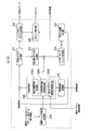
- FIG. 1 is a block diagram showing the configuration of the embodiment.
- the encoding / RD cost calculation processing unit 1 using IF performs encoding processing when an interpolation filter using a fixed coefficient is used as an interpolation filter, and calculates an RD cost. This RD cost is sent to the interpolation filter selection processing unit 6.
- the encoded data, decoded image, and motion vector related information obtained by the encoding process are stored in the encoded data storage unit 8, the decoded image storage unit 7, and the motion vector related information storage unit 2, respectively.
- the interpolation filter setting unit 31 sets a region division adaptive interpolation filter as an interpolation filter used in the subsequent encoding processing / RD cost calculation processing unit 32.
- the encoding process / RD cost calculation processing unit 32 performs an encoding process when a region-division adaptive interpolation filter is used as an interpolation filter, and calculates an RD cost. This RD cost is sent to the interpolation filter selection processing unit 6. Also, the encoded data and the decoded image obtained by the encoding process are sent to the encoded data storage unit 8 and the decoded image storage unit 7, respectively.
- the RD cost calculation execution determination unit 4 for the AIF obtains a lower limit value of the RD cost of the adaptive interpolation filter based on the coding distortion amount and the generated code amount used for calculating the RD cost of the region-division adaptive interpolation filter.
- the RD cost of the interpolation filter using a fixed coefficient is compared, and when the lower limit value is smaller, the encoding process / RD cost calculation processing unit 52 performs the process. Also, as an output of the encoding process / RD cost calculation processing unit 52, the RD cost, the encoded data obtained by the encoding process, and the decoded image are respectively converted into the interpolation filter selection processing unit 6, the encoded data storage unit 8, and the decoding Sending to the image storage unit 7 is permitted.
- the interpolation filter setting unit 51 sets an adaptive interpolation filter as an interpolation filter used in the subsequent encoding process / RD cost calculation unit 52.
- the encoding process / RD cost calculation processing unit 52 performs an encoding process when an adaptive interpolation filter is used as an interpolation filter, and calculates an RD cost. Also, the encoded data and decoded image obtained by the encoding process are output.
- the interpolation filter selection processing unit 6 selects an interpolation filter that minimizes the RD cost based on the input RD cost. Also, the encoded data when the selected interpolation filter is used is read from the encoded data storage unit 8 and output as final encoded data. Further, the decoded image when the selected interpolation filter is used is read from the decoded image storage unit 7 and stored in the reference image storage unit 9.
- FIG. 2 is a block diagram illustrating a configuration of the encoding and RD cost calculation processing unit 1 using IF when calculating motion vector related information.
- the transform / quantization processing unit 11 reads the prediction error signal as an input, performs orthogonal transform processing on the prediction error signal, further performs quantization on the transform coefficient of the orthogonal transform, and transforms the quantization of the transform coefficient. Output the index.
- the entropy encoding processing unit 121 reads the quantization index of the transform coefficient as an input, performs entropy encoding on the quantization index, and outputs encoded data.
- the entropy encoding processing unit 122 reads the motion vector related information as input, performs entropy encoding on the motion vector related information, and outputs encoded data.
- the inverse transform / inverse quantization processing unit 13 reads the quantization index of the transform coefficient as an input, inversely quantizes the quantization index, further performs inverse transform processing, and generates a decoded signal of the prediction error signal.
- the deblocking filter processing unit 14 reads, as an input, a signal generated by adding the decoded signal of the prediction error signal and the predicted image, performs filter processing on the addition result, generates a decoded image, and outputs the decoded image.
- the filter processing the standard H.264.
- a deblocking filter used in H.264 is applicable.
- the motion compensation prediction processing unit 161 reads the input image, the interpolation image and the reference image read from the motion compensation prediction processing unit 161 as inputs, performs a motion estimation process using the reference image on the input image, and performs motion vector related Calculate information.
- the decimal pixel position interpolation processing unit 162 reads a reference image as an input, and generates a pixel value at the decimal pixel position using an interpolation filter that uses a fixed coefficient as an interpolation filter.
- the motion vector related information calculation unit 163 reads the reference vector and the motion vector related information obtained by the decimal pixel position interpolation processing unit 162 as an input, and uses the reference image and the motion vector related information based on the motion compensation inter-screen prediction process.
- the prediction image for the input image is generated.
- the encoding distortion amount calculation unit 17 reads the input image and the decoded image output from the deblocking filter processing unit 14 as input, obtains the difference between both images, and calculates the encoding distortion amount.
- the RD cost 18 is calculated using the data amount (generated code amount) of the encoded data generated by the prediction processing unit 16 and the encoding distortion amount calculated by the encoding distortion amount calculating unit 17 as inputs. .
- FIG. 3 is a block diagram showing a detailed configuration of the encoding processing / RD cost calculation processing units 32 and 52 in FIG.
- the transform / quantization processing unit 321 reads the prediction error signal as an input, performs orthogonal transform processing on the prediction error signal, further performs quantization on the transform coefficient of the orthogonal transform, and transforms the quantization of the transform coefficient. Output the index.
- the entropy encoding processing unit 322 reads the quantization index of the transform coefficient as an input, performs entropy encoding on the quantization index, and outputs encoded data.
- the entropy encoding processing unit 327 reads the motion vector related information as an input, performs entropy encoding on the motion vector related information, and outputs encoded data.
- the inverse transform / inverse quantization processing unit 321 reads the quantization index of the transform coefficient as an input, inversely quantizes the quantization index, further performs inverse transform processing, and generates a prediction error signal decoded signal.
- the deblocking filter processing unit 324 reads, as an input, a signal generated by adding the decoded signal of the prediction error signal and the predicted image, performs filter processing on the addition result, generates a decoded image, and outputs the decoded image.
- the reference image storage unit 325 stores a reference image.
- the decimal pixel position interpolation processing unit 3261 reads the reference image as an input, reads the input image, the reference image, and the motion vector related information read by the motion vector related information calculation unit 3262 as an input, and is set by the interpolation filter setting processing unit 329.
- the filter coefficient for the interpolation filter (adaptive interpolation filter or area division adaptive interpolation filter) is calculated. The specific calculation method is as described above. Further, a pixel value at a decimal pixel position is generated using the calculated filter coefficient.
- the motion vector related information calculation unit 3262 reads and stores motion vector related information used for inter-screen prediction for the input image and the reference image from the outside.
- the motion compensation prediction processing unit 3263 reads the reference image, the interpolation image read from the decimal pixel position interpolation processing unit 3261, and the motion vector related information read from the motion vector related information calculation unit 3262 as inputs, and reads the reference image and the motion vector related information. Is used to generate a predicted image for the input image based on the motion compensation inter-screen prediction process.
- the encoding distortion amount calculation unit 327 reads the input image and the decoded image output from the deblocking filter processing unit 324 as input, obtains the difference between both images, and calculates the encoding distortion amount.
- the RD cost 328 calculates the RD cost with the data amount (generated code amount) of the encoded data generated by the prediction processing unit 326 and the encoded distortion amount calculated by the encoded distortion amount calculating unit 327 as inputs. .
- the interpolation filter setting processing unit 329 sets a filter used as an interpolation filter.
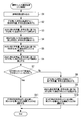
- FIG. 4 is a flowchart showing the processing operation of the video encoding apparatus shown in FIG.
- step S6 the value of the parameter ⁇ is read, and D R + ⁇ (r R + ⁇ R ) is obtained as the lower limit value of the RD cost of the adaptive interpolation filter (step S6), and the lower limit of the RD cost of the adaptive interpolation filter obtained in step S6
- step S7 The RD cost of the interpolation filter using the value and the fixed coefficient obtained in step S2 is compared (step S7), and if the former is larger, the process proceeds to step S8. Otherwise, the process proceeds to step S11.
- the encoding process / RD cost calculation processing unit 52 performs an encoding process using an adaptive interpolation filter as an interpolation filter, and is generated.
- the interpolation filter selection processing unit 6 compares the RD costs J I , J A , and J R of the interpolation filter using the fixed coefficient, the adaptive interpolation filter, and the area division adaptive interpolation filter, and selects the interpolation filter that minimizes the cost. (Step S10).
- the interpolation filter selection processing unit 6 compares the RD costs J I and J R of the interpolation filter using the fixed coefficient and the area division adaptive interpolation filter. Then, an interpolation filter that minimizes the cost is selected (step S11).
- FIG. 5 illustrates a process in which the encoding / RD cost calculation processing unit 1 using the IF illustrated in FIG. 1 performs the “encoding process using the IF to calculate the generated code amount and the encoding distortion” illustrated in FIG. It is a flowchart which shows the detailed operation
- the encoding / RD cost calculation processing unit 1 using IF reads a reference image used for inter-frame prediction (step S21). Then, the decimal pixel position interpolation processing unit 162 reads the reference image as an input, and generates a pixel value at the decimal pixel position using an interpolation filter that uses a fixed coefficient as an interpolation filter (step S22). Subsequently, the motion vector related information calculation unit 163 reads the input image and the reference image as inputs, performs a motion estimation process using the reference image on the input image, and calculates motion vector related information (step S23). .
- the motion compensation prediction processing unit 161 reads the reference image and the obtained motion vector related information as an input, and uses the reference image and the obtained motion vector related information to perform an input image based on the motion compensation inter-screen prediction process.
- a predicted image is generated (step S24).
- the predicted image and the input image are read as inputs, the difference between the two images is obtained, and a prediction error signal is generated (step S25).
- the transform / quantization processing unit 11 reads the prediction error signal as input, performs orthogonal transform processing on the prediction error signal, further performs quantization on transform coefficients of the orthogonal transform, and transforms The coefficient quantization index is output (step S26).
- the entropy encoding processing unit 121 reads the transform coefficient quantization index and motion vector related information as inputs, entropy encodes the quantization index and motion vector related information, and outputs encoded data (step). S27).
- the inverse transform / inverse quantization processing unit 13 reads the quantization index of the transform coefficient as an input, inversely quantizes the quantized index, performs further inverse transform processing, and generates a decoded signal of the prediction error signal. (Step S28). Subsequently, the decoded signal of the generated prediction error signal and the generated prediction image are read as inputs, both are added, and the addition result is subjected to filter processing by the deblocking filter processing unit 14 to be decoded. An image is generated and output (step S29).
- the coding distortion amount calculation unit 17 reads the input image and the output decoded image as inputs, obtains the difference between the two images, and calculates the coding distortion amount (step 30). Subsequently, the RD cost calculation unit 18 reads the generated encoded data as an input, calculates a generated code amount based on the data amount of the data (step S31), and weights the encoded distortion amount and the generated code amount. The RD cost is calculated as the sum (step S32).
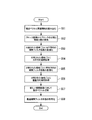
- FIG. 6 is a flowchart showing detailed operations of the processing for calculating the generated code amount and the encoding distortion shown in FIG. 4 by the encoding processing / RD cost calculation processing units 32 and 52 shown in FIG.
- the encoding / RD cost calculation processing units 32 and 52 read a reference image used for inter-frame prediction (step S41). Then, the motion vector related information calculation unit 3362 reads motion vector related information necessary for the motion estimation process (step S42). Subsequently, the input image, the reference image, and the read motion vector related information are read as inputs, and filter coefficients for the interpolation filter (region-division adaptive interpolation filter or adaptive interpolation filter) given as the input of this processing are calculated (step S43). ).
- the decimal pixel position interpolation processing unit 3261 reads the reference image as an input, and uses the interpolation filter (region division adaptive interpolation filter or adaptive interpolation filter) given as an input of this processing to calculate the pixel value at the decimal pixel position. Generate (step S44). Subsequently, the motion compensation prediction processing unit 3263 reads the read motion vector related information and the reference image as inputs, and generates a prediction image for the input image based on the motion compensation inter-screen prediction process (step S45). Then, the prediction image and the input image are read as inputs, the difference between the two images is obtained, and a prediction error signal is generated (step S46).
- the interpolation filter region division adaptive interpolation filter or adaptive interpolation filter
- the transform / quantization processing unit 321 reads the prediction error signal as input, performs orthogonal transform processing on the prediction error signal, further performs quantization on transform coefficients of the orthogonal transform, and transforms The coefficient quantization index is output (step S47).
- the entropy encoding processing unit 322 reads the transform coefficient quantization index and motion vector related information as inputs, entropy encodes the quantization index and motion vector related information, and outputs encoded data (step). S48).
- the inverse transform / inverse quantization processing unit 323 reads the quantization index of the transform coefficient as an input, inversely quantizes the quantization index, further performs inverse transform processing, and generates a decoded signal of the prediction error signal. (Step S49). Subsequently, the decoded signal of the generated prediction error signal and the generated prediction image are read as inputs, and both are added. Further, the addition result is subjected to filter processing by the deblocking filter processing unit 324 and decoded. An image is generated and output (step S50).
- the coding distortion amount calculation unit 327 reads the input image and the output decoded image as inputs, obtains the difference between the two images, and calculates the coding distortion amount (step 51).
- the RD cost calculation unit 328 reads the generated encoded data as input, calculates the generated code amount based on the data amount of the data (step S52), and weights the encoded distortion amount and the generated code amount. The RD cost is calculated as the sum (step S53).
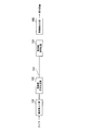
- FIG. 8 is a block diagram showing a configuration of the moving image transmission system.
- a moving image input unit 101 inputs a moving image captured by a camera or the like.
- Reference numeral 102 denotes the moving image encoding apparatus shown in FIG. 1, which encodes and transmits the moving image input by the moving image input unit 101.
- Reference numeral 103 denotes a transmission path for transmitting encoded moving image data transmitted from the moving image encoding apparatus 102.
- Reference numeral 1044 denotes a moving picture decoding apparatus that receives encoded moving picture data transmitted through the transmission path 103, decodes the encoded moving picture data, and outputs the decoded moving picture data.
- the moving image output unit 105 outputs the moving image decoded by the moving image decoding device 104 to a display device or the like.
- the moving image encoding apparatus 102 inputs moving image data via the moving image input unit 1 and performs encoding for each frame of the moving image.
- the interpolation filter selection process shown in FIG. 1 is performed, and the encoding process and the RD cost calculation process shown in FIGS. 2 and 3 are performed.
- the moving image encoding device 102 transmits the encoded moving image data to the moving image decoding device 104 via the transmission path 103.
- the moving image decoding device 104 decodes the encoded moving image data, and displays the moving image on a display device or the like via the moving image output unit 105.
- a program for realizing the functions of the respective processing units in FIG. 1 is recorded on a computer-readable recording medium, and the program recorded on the recording medium is read into a computer system and executed to cope with area division.
- An adaptive filter process may be performed.
- the “computer system” includes an OS and hardware such as peripheral devices.
- the “computer-readable recording medium” refers to a storage device such as a flexible medium, a magneto-optical disk, a portable medium such as a ROM or a CD-ROM, and a hard disk incorporated in a computer system.
- the “computer-readable recording medium” refers to a volatile memory (RAM) in a computer system that becomes a server or a client when a program is transmitted via a network such as the Internet or a communication line such as a telephone line. In addition, those holding programs for a certain period of time are also included.
- RAM volatile memory
- the program may be transmitted from a computer system storing the program in a storage device or the like to another computer system via a transmission medium or by a transmission wave in the transmission medium.
- the “transmission medium” for transmitting the program refers to a medium having a function of transmitting information, such as a network (communication network) such as the Internet or a communication line (communication line) such as a telephone line.
- the program may be for realizing a part of the functions described above. Furthermore, what can implement
- the moving picture encoding apparatus can be applied to an application in which it is indispensable to reduce the amount of calculation for selecting an interpolation filter while suppressing a decrease in encoding efficiency.
Landscapes
- Engineering & Computer Science (AREA)
- Multimedia (AREA)
- Signal Processing (AREA)
- Compression Or Coding Systems Of Tv Signals (AREA)
Abstract
Description
本願は、2011年6月13日に、日本に出願された特願2011-131126号に基づき優先権を主張し、その内容をここに援用する。


このため、IF、AIF、RBAIFの優劣は一概には言えず、予測誤差エネルギーとフィルタ係数の符号量を考慮した符号化効率の観点から、フレーム毎に、最適なフィルタを選択する必要がある。
J=D+λR
ここで、Dは復号信号の符号化歪量であり、Rはフレーム内の総発生符号量であり、λは外部から与えれる重み係数である。なお、Rについては、フィルタ係数の符号量ρとそれ以外の符号量r(予測誤差を表現する符号量r(e)、動きベクトルを表現する符号量r(m)、各種ヘッダ情報を表現する符号量r(h)の和)に分離可能である。
RI=rI=rI (e)+rI (m)+rI (h)
RA=rA+ρA=rA (e)+rA (m)+rA (h)+ρA
RR=rR+ρR=rR (e)+rR (m)+rR (h)+ρR
上式において、rX (e),rX (m), rX (h)(X=I,A,R)は、各々、各補間フィルタを用いた場合の予測誤差を表現する符号量、動きベクトルを表現する符号量、各種ヘッダ情報を表現する符号量を表す。ρA,ρRは、各々、AIF、RBAIFを用いた場合のフィルタ係数の符号量である。なお、IFは固定値のフィルタ係数を用いるため、フィルタ係数の符号量は不要となる。
JI=DI+λrI ・・・(3)
JA=DA+λ(rA+ρA)・・・(4)
JR=DR+λ(rR+ρR)・・・(5)
JI=DI+λrI
この際、求めた画面間予測に関連する情報(予測を行うブロックのサイズ、動きベクトル、動き補償の参照画像等)を動きベクトル関連情報として格納する。なお、前記の動きベクトル関連情報を求めるための動き推定等のアルゴリズムは、外部から与えられるものとする。例えば、文献「K. P. Lim, G. Sullivan, and T. Wiegand. Text description of joint model reference encoding methods and decoding concealment methods. Technical Report R095, Joint Video Team (JVT) of ISO/IEC MPEG and ITU-T VCEG,Jan. 2006.」に記載されたものを用いる。
フィルタ係数算出は予測誤差エネルギー最小化の規範に基づいて行う。詳細については、後述する。この処理により求めた領域分割適応補間フィルタを用いた場合のRDコストJRを前述した式(5)から以下のように算出する。
JR=DR+λ(rR+ρR)
DA≧DR
rA (m)=rR (m)である。領域分割適応補間フィルタの方が適応補間フィルタよりも予測誤差を低減可能なことから予測誤差を表現する符号量については、
rA (e)≧rR (e)である。ヘッダ情報については、ほぼ同程度とみなすことができる。
rA (e)≒rR (e)
ρA≦ρR
となる。ここで、β≦1を用いて、上記の不等式は次式の形式で表すことができる。
ρA=βρR
JA=DA+λ(rA+ρA)・・・(6)
JA≧DR+λ(rR+βρR)・・・(7)


動き補償予測処理部3263は、参照画像、小数画素位置補間処理部3261から読み込んだ補間画像及び動きベクトル関連情報算出部3262から読み込んだ動きベクトル関連情報を入力として読み込み、参照画像及び動きベクトル関連情報を用いて、動き補償画面間予測処理に基づき、入力画像に対する予測画像を生成する。
なお、ここでいう「コンピュータシステム」とは、OSや周辺機器等のハードウェアを含むものとする。また、「コンピュータ読み取り可能な記録媒体」とは、フレキシブルディスク、光磁気ディスク、ROM、CD-ROM等の可搬媒体、コンピュータシステムに内蔵されるハードディスク等の記憶装置のことをいう。さらに「コンピュータ読み取り可能な記録媒体」とは、インターネット等のネットワークや電話回線等の通信回線を介してプログラムが送信された場合のサーバやクライアントとなるコンピュータシステム内部の揮発性メモリ(RAM)のように、一定時間プログラムを保持しているものも含むものとする。
2 動きベクトル関連情報記憶部
4 AIFに対するRDコスト算出実行判定部
6 補間フィルタ選択処理部
7 復号画像記憶部
8 符号化データ記憶部
9 参照画像記憶部
11 変換・量子化処理部
13 逆変換・逆量子化処理部
14 デブロッキングフィルタ処理部
15 参照画像記憶部
16 予測処理部
17 符号化歪量算出部
18 RDコスト算出部
31 補間フィルタ設定部
32 符号化処理・RDコスト算出処理部
51 補間フィルタ設定部
52 符号化処理・RDコスト算出処理部
101 動画像入力部
102 動画像符号化装置
103 伝送路
104 動画像復号装置
105 動画像出力部
121 エントロピー符号化処理部
122 エントロピー符号化処理部
161 動き補償予測処理部
162 小数画素位置補間処理部
163 動きベクトル関連情報算出部
321 変換・量子化処理部
322 エントロピー符号化処理部
323 逆変換・逆量子化処理部
324 デブロッキングフィルタ処理部
325 参照画像記憶部
326 予測処理部
327 符号化歪量算出部
328 RDコスト算出部
329 補間フィルタ設定処理部
3261 小数画素位置補間処理部
3262 動きベクトル関連情報算出部
3263 動き補償予測処理部
Claims (6)
- 小数画素位置の補間画素値を生成する補間フィルタとして、固定値の係数を用いる固定補間フィルタと、補間フィルタの係数を適応的に設定する適応補間フィルタと、フレーム内を複数の領域に分割して、各分割領域毎に補間フィルタの係数を適応的に設定する領域分割対応適応補間フィルタとを備え、小数画素精度に対応した動き補償フレーム間予測を行う動画像符号化装置であって、
前記固定補間フィルタ、前記適応補間フィルタ及び前記領域分割対応適応補間フィルタのうち、符号量・歪コスト関数に基づき最適な補間フィルタを選択する際、前記領域分割対応適応補間フィルタを用いた場合の発生符号量及び符号化歪量に基づき、前記適応補間フィルタを用いた場合の符号量・歪コスト関数の下限値を推定する下限値推定部と、
前記下限値が前記固定補間フィルタに対する符号量・歪コスト関数よりも大きな値となる場合は、前記固定補間フィルタおよび前記領域分割対応適応補間フィルタの符号量・歪コスト関数の比較に基づき、最適な補間フィルタを選択し、前記下限値が前記固定補間フィルタに対する符号量・歪コスト関数以下となる場合のみ、前記固定補間フィルタ、前記適応補間フィルタ及び前記領域分割対応適応補間フィルタの符号量・歪コスト関数の比較に基づき、最適な補間フィルタを選択する補間フィルタ選択部とを備えた動画像符号化装置。 - 請求項1に記載の動画像符号化装置によって符号化された動画像を復号する動画像復号装置。
- 小数画素位置の補間画素値を生成する補間フィルタとして、固定値の係数を用いる固定補間フィルタと、補間フィルタの係数を適応的に設定する適応補間フィルタと、フレーム内を複数の領域に分割して、各分割領域毎に補間フィルタの係数を適応的に設定する領域分割対応適応補間フィルタとを備え、小数画素精度に対応した動き補償フレーム間予測を行う動画像符号化装置における動画像符号化方法であって、
前記固定補間フィルタ、前記適応補間フィルタ及び前記領域分割対応適応補間フィルタのうち、符号量・歪コスト関数に基づき最適な補間フィルタを選択する際、前記領域分割対応適応補間フィルタを用いた場合の発生符号量及び符号化歪量に基づき、前記適応補間フィルタを用いた場合の符号量・歪コスト関数の下限値を推定する下限値推定ステップと、
前記下限値が前記固定補間フィルタに対する符号量・歪コスト関数よりも大きな値となる場合は、前記固定補間フィルタおよび前記領域分割対応適応補間フィルタの符号量・歪コスト関数の比較に基づき、最適な補間フィルタを選択し、前記下限値が前記固定補間フィルタに対する符号量・歪コスト関数以下となる場合のみ、前記固定補間フィルタ、前記適応補間フィルタ及び前記領域分割対応適応補間フィルタの符号量・歪コスト関数の比較に基づき、最適な補間フィルタを選択する補間フィルタ選択ステップとを有する動画像符号化方法。 - 請求項3に記載の動画像符号化方法によって符号化された動画像を復号する動画像復号方法。
- 小数画素位置の補間画素値を生成する補間フィルタとして、固定値の係数を用いる固定補間フィルタと、補間フィルタの係数を適応的に設定する適応補間フィルタと、フレーム内を複数の領域に分割して、各分割領域毎に補間フィルタの係数を適応的に設定する領域分割対応適応補間フィルタとを備え、小数画素精度に対応した動き補償フレーム間予測を行う動画像符号化装置上のコンピュータに動画像符号化処理を行わせる動画像符号化プログラムであって、
前記固定補間フィルタ、前記適応補間フィルタ及び前記領域分割対応適応補間フィルタのうち、符号量・歪コスト関数に基づき最適な補間フィルタを選択する際、前記領域分割対応適応補間フィルタを用いた場合の発生符号量及び符号化歪量に基づき、前記適応補間フィルタを用いた場合の符号量・歪コスト関数の下限値を推定する下限値推定ステップと、
前記下限値が前記固定補間フィルタに対する符号量・歪コスト関数よりも大きな値となる場合は、前記固定補間フィルタおよび前記領域分割対応適応補間フィルタの符号量・歪コスト関数の比較に基づき、最適な補間フィルタを選択し、前記下限値が前記固定補間フィルタに対する符号量・歪コスト関数以下となる場合のみ、前記固定補間フィルタ、前記適応補間フィルタ及び前記領域分割対応適応補間フィルタの符号量・歪コスト関数の比較に基づき、最適な補間フィルタを選択する補間フィルタ選択ステップとを前記コンピュータに行わせる動画像符号化プログラム。 - 請求項5に記載の動画像符号化プログラムによって符号化された動画像を復号する動画像復号プログラム。
Priority Applications (7)
| Application Number | Priority Date | Filing Date | Title |
|---|---|---|---|
| KR1020137032841A KR20140010174A (ko) | 2011-06-13 | 2012-06-12 | 동화상 부호화 장치, 동화상 복호 장치, 동화상 부호화 방법, 동화상 복호 방법, 동화상 부호화 프로그램 및 동화상 복호 프로그램 |
| US14/125,125 US20140133546A1 (en) | 2011-06-13 | 2012-06-12 | Video encoding device, video decoding device, video encoding method, video decoding method, video encoding program, and video decoding program |
| RU2013154581/08A RU2013154581A (ru) | 2011-06-13 | 2012-06-12 | Устройство кодирования видео, устройство декодирования видео, способ кодирования видео, способ декодирования видео, программа кодирования видео и программа декодирования видео |
| CA 2838972 CA2838972A1 (en) | 2011-06-13 | 2012-06-12 | Video encoding device, video decoding device, video encoding method, video decoding method, video encoding program, and video decoding program |
| CN201280028377.7A CN103583046A (zh) | 2011-06-13 | 2012-06-12 | 视频编码装置、视频解码装置、视频编码方法、视频解码方法、视频编码程序以及视频解码程序 |
| BR112013031777A BR112013031777A2 (pt) | 2011-06-13 | 2012-06-12 | dispositivo de codificação de vídeo, dispositivo de decodificação de vídeo, método de codificação de vídeo, método de decodificação de vídeo, programa de codificação de vídeo, e programa de decodificação de vídeo |
| EP12800566.7A EP2709363A4 (en) | 2011-06-13 | 2012-06-12 | VIDEO ENCODER, VIDEO ENCODER, VIDEO ENCODER, VIDEO ENCODER, VIDEO ENCODER, AND VIDEO ENCODER |
Applications Claiming Priority (2)
| Application Number | Priority Date | Filing Date | Title |
|---|---|---|---|
| JP2011131126A JP5552092B2 (ja) | 2011-06-13 | 2011-06-13 | 動画像符号化装置、動画像符号化方法及び動画像符号化プログラム |
| JP2011-131126 | 2011-06-13 |
Publications (1)
| Publication Number | Publication Date |
|---|---|
| WO2012173109A1 true WO2012173109A1 (ja) | 2012-12-20 |
Family
ID=47357096
Family Applications (1)
| Application Number | Title | Priority Date | Filing Date |
|---|---|---|---|
| PCT/JP2012/064996 Ceased WO2012173109A1 (ja) | 2011-06-13 | 2012-06-12 | 動画像符号化装置、動画像復号装置、動画像符号化方法、動画像復号方法、動画像符号化プログラム及び動画像復号プログラム |
Country Status (10)
| Country | Link |
|---|---|
| US (1) | US20140133546A1 (ja) |
| EP (1) | EP2709363A4 (ja) |
| JP (1) | JP5552092B2 (ja) |
| KR (1) | KR20140010174A (ja) |
| CN (1) | CN103583046A (ja) |
| BR (1) | BR112013031777A2 (ja) |
| CA (1) | CA2838972A1 (ja) |
| RU (1) | RU2013154581A (ja) |
| TW (1) | TW201306594A (ja) |
| WO (1) | WO2012173109A1 (ja) |
Families Citing this family (9)
| Publication number | Priority date | Publication date | Assignee | Title |
|---|---|---|---|---|
| KR102402671B1 (ko) | 2015-09-09 | 2022-05-26 | 삼성전자주식회사 | 보간 필터의 연산 복잡도를 조절할 수 있는 영상 처리 장치, 영상 보간 방법 및 영상 부호화 방법 |
| JP6678735B2 (ja) | 2015-09-25 | 2020-04-08 | 華為技術有限公司Huawei Technologies Co.,Ltd. | 予測符号化のための適応シャープニングフィルタ |
| MY185713A (en) | 2015-09-25 | 2021-05-31 | Huawei Tech Co Ltd | Apparatus and method for video motion compensation |
| BR112018006031A2 (pt) | 2015-09-25 | 2018-10-09 | Huawei Tech Co Ltd | codificador de vídeo, decodificador de vídeo e métodos para codificação e decodificação preditiva |
| CA2999826C (en) | 2015-09-25 | 2020-10-13 | Huawei Technologies Co., Ltd. | Apparatus and method for video motion compensation with selectable interpolation filter |
| JP6673599B2 (ja) | 2015-09-25 | 2020-03-25 | ホアウェイ・テクノロジーズ・カンパニー・リミテッド | ビデオ動き補償のための装置及び方法 |
| KR102631802B1 (ko) * | 2018-09-05 | 2024-01-31 | 엘지전자 주식회사 | 비디오 신호의 부호화/복호화 방법 및 이를 위한 장치 |
| US12375718B2 (en) * | 2019-05-30 | 2025-07-29 | Sharp Kabushiki Kaisha | Image decoding apparatus |
| US20240275984A1 (en) * | 2021-06-04 | 2024-08-15 | Beijing Bytedance Network Technology Co., Ltd. | Method, device, and medium for video processing |
Citations (3)
| Publication number | Priority date | Publication date | Assignee | Title |
|---|---|---|---|---|
| JP2004147328A (ja) * | 2002-10-22 | 2004-05-20 | Docomo Communications Laboratories Usa Inc | 動き補償予測を用いたビデオ符号化のための適応補間フィルタシステム |
| WO2010005808A1 (en) * | 2008-07-07 | 2010-01-14 | Qualcomm Incorporated | Video encoding by filter selection |
| JP2011131126A (ja) | 2009-12-22 | 2011-07-07 | Toyota Motor Corp | グラビア塗工装置 |
Family Cites Families (8)
| Publication number | Priority date | Publication date | Assignee | Title |
|---|---|---|---|---|
| JP4494789B2 (ja) * | 2002-01-14 | 2010-06-30 | ノキア コーポレイション | 動的フィルタのコーディング |
| WO2008148272A1 (en) * | 2007-06-04 | 2008-12-11 | France Telecom Research & Development Beijing Company Limited | Method and apparatus for sub-pixel motion-compensated video coding |
| CN101170701B (zh) * | 2007-11-16 | 2010-10-27 | 四川虹微技术有限公司 | 视频编解码系统中去块滤波方法及装置 |
| US8831086B2 (en) * | 2008-04-10 | 2014-09-09 | Qualcomm Incorporated | Prediction techniques for interpolation in video coding |
| US9967590B2 (en) * | 2008-04-10 | 2018-05-08 | Qualcomm Incorporated | Rate-distortion defined interpolation for video coding based on fixed filter or adaptive filter |
| CN101296380A (zh) * | 2008-06-20 | 2008-10-29 | 四川虹微技术有限公司 | 运动补偿系统中的插值方法及插值器 |
| US20120033040A1 (en) * | 2009-04-20 | 2012-02-09 | Dolby Laboratories Licensing Corporation | Filter Selection for Video Pre-Processing in Video Applications |
| EP2296380A1 (en) * | 2009-09-03 | 2011-03-16 | Panasonic Corporation | Efficient syntax for AIF signalling |
-
2011
- 2011-06-13 JP JP2011131126A patent/JP5552092B2/ja active Active
-
2012
- 2012-06-11 TW TW101120878A patent/TW201306594A/zh unknown
- 2012-06-12 BR BR112013031777A patent/BR112013031777A2/pt not_active IP Right Cessation
- 2012-06-12 RU RU2013154581/08A patent/RU2013154581A/ru not_active Application Discontinuation
- 2012-06-12 EP EP12800566.7A patent/EP2709363A4/en not_active Withdrawn
- 2012-06-12 CN CN201280028377.7A patent/CN103583046A/zh active Pending
- 2012-06-12 WO PCT/JP2012/064996 patent/WO2012173109A1/ja not_active Ceased
- 2012-06-12 CA CA 2838972 patent/CA2838972A1/en not_active Abandoned
- 2012-06-12 US US14/125,125 patent/US20140133546A1/en not_active Abandoned
- 2012-06-12 KR KR1020137032841A patent/KR20140010174A/ko not_active Ceased
Patent Citations (3)
| Publication number | Priority date | Publication date | Assignee | Title |
|---|---|---|---|---|
| JP2004147328A (ja) * | 2002-10-22 | 2004-05-20 | Docomo Communications Laboratories Usa Inc | 動き補償予測を用いたビデオ符号化のための適応補間フィルタシステム |
| WO2010005808A1 (en) * | 2008-07-07 | 2010-01-14 | Qualcomm Incorporated | Video encoding by filter selection |
| JP2011131126A (ja) | 2009-12-22 | 2011-07-07 | Toyota Motor Corp | グラビア塗工装置 |
Non-Patent Citations (5)
| Title |
|---|
| K. P. LIM; G. SULLIVAN; T. WIEGAND: "Text description of joint model reference encoding methods and decoding concealment methods", TECHNICAL REPORT R095, JOINT VIDEO TEAM (JVT) OFISO/IEC MPEG AND ITU-T VCEG, January 2006 (2006-01-01) |
| MATSUO,S. ET AL.: "CE3: Region-based adaptive interpolation filter", JOINT COLLABORATIVE TEAM ON VIDEO CODING (JCT-VC)OF ITU-T SG16 WP3 AND ISO/IEC JTC1/SC29/WG11 5TH MEETING JCTVC-E078, 18 March 2011 (2011-03-18), XP030048157 * |
| S. WITTMANN; T. WEDI: "Separable adaptive interpolation filter for video coding", IEEE INTERNATIONAL CONFERENCE ON IMAGE PROCESSING, 2008, pages 2500 - 2503 |
| See also references of EP2709363A4 * |
| Y. VATIS; B. EDLER; D. NGUYEN; J. OSTERMANN: "ITU-TQ.6/SG16 VCEG, VCEG-Zl7rl", April 2005, article "Two-dimensional non-separable adaptive wiener interpolation filter for H.264/AVC" |
Also Published As
| Publication number | Publication date |
|---|---|
| JP2013005019A (ja) | 2013-01-07 |
| CA2838972A1 (en) | 2012-12-20 |
| EP2709363A4 (en) | 2014-09-24 |
| US20140133546A1 (en) | 2014-05-15 |
| CN103583046A (zh) | 2014-02-12 |
| BR112013031777A2 (pt) | 2016-12-06 |
| RU2013154581A (ru) | 2015-07-20 |
| EP2709363A1 (en) | 2014-03-19 |
| TW201306594A (zh) | 2013-02-01 |
| KR20140010174A (ko) | 2014-01-23 |
| JP5552092B2 (ja) | 2014-07-16 |
Similar Documents
| Publication | Publication Date | Title |
|---|---|---|
| JP5552092B2 (ja) | 動画像符号化装置、動画像符号化方法及び動画像符号化プログラム | |
| JP6545838B2 (ja) | マージ候補ブロック誘導方法及びこのような方法を用いる装置 | |
| JP5563403B2 (ja) | 映像符号化方法,映像復号方法,映像符号化装置,映像復号装置およびそれらのプログラム | |
| JP5649524B2 (ja) | 映像符号化方法,装置,映像復号方法,装置およびそれらのプログラム | |
| US9609318B2 (en) | Video encoding method, video decoding method, video encoding apparatus, video decoding apparatus, and programs thereof | |
| WO2013002144A1 (ja) | 映像符号化方法,装置,映像復号方法,装置およびそれらのプログラム | |
| JP5762243B2 (ja) | 映像符号化方法,装置,映像復号方法,装置およびそれらのプログラム | |
| JP5552093B2 (ja) | 動画像符号化装置、動画像符号化方法及び動画像符号化プログラム | |
| JP5488684B2 (ja) | 画像処理装置および方法、プログラム、並びに記録媒体 | |
| JP5488685B2 (ja) | 画像処理装置および方法、プログラム、並びに記録媒体 | |
| KR101524664B1 (ko) | 참조 프레임 생성 방법 및 장치와 그를 이용한 영상 부호화/복호화 방법 및 장치 | |
| KR101533435B1 (ko) | 참조 프레임 생성 방법 및 장치와 그를 이용한 영상 부호화/복호화 방법 및 장치 | |
| KR101533441B1 (ko) | 참조 프레임 생성 방법 및 장치와 그를 이용한 영상 부호화/복호화 방법 및 장치 | |
| KR101479525B1 (ko) | 참조 프레임 생성 방법 및 장치와 그를 이용한 영상 부호화/복호화 방법 및 장치 | |
| JP6102977B2 (ja) | 画像処理装置および方法、プログラム、並びに記録媒体 | |
| JP2021118525A (ja) | 符号化装置、復号装置、及びプログラム | |
| JP2015167387A (ja) | 画像処理装置および方法、プログラム、並びに記録媒体 | |
| JP2014112941A (ja) | 画像処理装置および方法、並びに記録媒体 | |
| JP2014135742A (ja) | 画像処理装置および方法、並びに記録媒体 |
Legal Events
| Date | Code | Title | Description |
|---|---|---|---|
| 121 | Ep: the epo has been informed by wipo that ep was designated in this application |
Ref document number: 12800566 Country of ref document: EP Kind code of ref document: A1 |
|
| WWE | Wipo information: entry into national phase |
Ref document number: 2012800566 Country of ref document: EP |
|
| ENP | Entry into the national phase |
Ref document number: 20137032841 Country of ref document: KR Kind code of ref document: A Ref document number: 2838972 Country of ref document: CA |
|
| WWE | Wipo information: entry into national phase |
Ref document number: 14125125 Country of ref document: US |
|
| NENP | Non-entry into the national phase |
Ref country code: DE |
|
| ENP | Entry into the national phase |
Ref document number: 2013154581 Country of ref document: RU Kind code of ref document: A |
|
| REG | Reference to national code |
Ref country code: BR Ref legal event code: B01A Ref document number: 112013031777 Country of ref document: BR |
|
| ENP | Entry into the national phase |
Ref document number: 112013031777 Country of ref document: BR Kind code of ref document: A2 Effective date: 20131210 |