WO2012173125A1 - 動画像符号化装置、動画像復号装置、動画像符号化方法、動画像復号方法、動画像符号化プログラム及び動画像復号プログラム - Google Patents
動画像符号化装置、動画像復号装置、動画像符号化方法、動画像復号方法、動画像符号化プログラム及び動画像復号プログラム Download PDFInfo
- Publication number
- WO2012173125A1 WO2012173125A1 PCT/JP2012/065045 JP2012065045W WO2012173125A1 WO 2012173125 A1 WO2012173125 A1 WO 2012173125A1 JP 2012065045 W JP2012065045 W JP 2012065045W WO 2012173125 A1 WO2012173125 A1 WO 2012173125A1
- Authority
- WO
- WIPO (PCT)
- Prior art keywords
- interpolation filter
- divided
- coefficient
- equation
- region
- Prior art date
- Legal status (The legal status is an assumption and is not a legal conclusion. Google has not performed a legal analysis and makes no representation as to the accuracy of the status listed.)
- Ceased
Links
Images


Classifications
-
- H—ELECTRICITY
- H04—ELECTRIC COMMUNICATION TECHNIQUE
- H04N—PICTORIAL COMMUNICATION, e.g. TELEVISION
- H04N19/00—Methods or arrangements for coding, decoding, compressing or decompressing digital video signals
- H04N19/50—Methods or arrangements for coding, decoding, compressing or decompressing digital video signals using predictive coding
- H04N19/503—Methods or arrangements for coding, decoding, compressing or decompressing digital video signals using predictive coding involving temporal prediction
- H04N19/51—Motion estimation or motion compensation
- H04N19/513—Processing of motion vectors
- H04N19/517—Processing of motion vectors by encoding
- H04N19/52—Processing of motion vectors by encoding by predictive encoding
-
- H—ELECTRICITY
- H04—ELECTRIC COMMUNICATION TECHNIQUE
- H04N—PICTORIAL COMMUNICATION, e.g. TELEVISION
- H04N19/00—Methods or arrangements for coding, decoding, compressing or decompressing digital video signals
- H04N19/10—Methods or arrangements for coding, decoding, compressing or decompressing digital video signals using adaptive coding
- H04N19/102—Methods or arrangements for coding, decoding, compressing or decompressing digital video signals using adaptive coding characterised by the element, parameter or selection affected or controlled by the adaptive coding
- H04N19/117—Filters, e.g. for pre-processing or post-processing
-
- H—ELECTRICITY
- H04—ELECTRIC COMMUNICATION TECHNIQUE
- H04N—PICTORIAL COMMUNICATION, e.g. TELEVISION
- H04N19/00—Methods or arrangements for coding, decoding, compressing or decompressing digital video signals
- H04N19/10—Methods or arrangements for coding, decoding, compressing or decompressing digital video signals using adaptive coding
- H04N19/102—Methods or arrangements for coding, decoding, compressing or decompressing digital video signals using adaptive coding characterised by the element, parameter or selection affected or controlled by the adaptive coding
- H04N19/124—Quantisation
-
- H—ELECTRICITY
- H04—ELECTRIC COMMUNICATION TECHNIQUE
- H04N—PICTORIAL COMMUNICATION, e.g. TELEVISION
- H04N19/00—Methods or arrangements for coding, decoding, compressing or decompressing digital video signals
- H04N19/10—Methods or arrangements for coding, decoding, compressing or decompressing digital video signals using adaptive coding
- H04N19/169—Methods or arrangements for coding, decoding, compressing or decompressing digital video signals using adaptive coding characterised by the coding unit, i.e. the structural portion or semantic portion of the video signal being the object or the subject of the adaptive coding
- H04N19/17—Methods or arrangements for coding, decoding, compressing or decompressing digital video signals using adaptive coding characterised by the coding unit, i.e. the structural portion or semantic portion of the video signal being the object or the subject of the adaptive coding the unit being an image region, e.g. an object
- H04N19/174—Methods or arrangements for coding, decoding, compressing or decompressing digital video signals using adaptive coding characterised by the coding unit, i.e. the structural portion or semantic portion of the video signal being the object or the subject of the adaptive coding the unit being an image region, e.g. an object the region being a slice, e.g. a line of blocks or a group of blocks
-
- H—ELECTRICITY
- H04—ELECTRIC COMMUNICATION TECHNIQUE
- H04N—PICTORIAL COMMUNICATION, e.g. TELEVISION
- H04N19/00—Methods or arrangements for coding, decoding, compressing or decompressing digital video signals
- H04N19/50—Methods or arrangements for coding, decoding, compressing or decompressing digital video signals using predictive coding
- H04N19/503—Methods or arrangements for coding, decoding, compressing or decompressing digital video signals using predictive coding involving temporal prediction
- H04N19/51—Motion estimation or motion compensation
- H04N19/523—Motion estimation or motion compensation with sub-pixel accuracy
-
- H—ELECTRICITY
- H04—ELECTRIC COMMUNICATION TECHNIQUE
- H04N—PICTORIAL COMMUNICATION, e.g. TELEVISION
- H04N19/00—Methods or arrangements for coding, decoding, compressing or decompressing digital video signals
- H04N19/50—Methods or arrangements for coding, decoding, compressing or decompressing digital video signals using predictive coding
- H04N19/587—Methods or arrangements for coding, decoding, compressing or decompressing digital video signals using predictive coding involving temporal sub-sampling or interpolation, e.g. decimation or subsequent interpolation of pictures in a video sequence
-
- H—ELECTRICITY
- H04—ELECTRIC COMMUNICATION TECHNIQUE
- H04N—PICTORIAL COMMUNICATION, e.g. TELEVISION
- H04N19/00—Methods or arrangements for coding, decoding, compressing or decompressing digital video signals
- H04N19/80—Details of filtering operations specially adapted for video compression, e.g. for pixel interpolation
- H04N19/82—Details of filtering operations specially adapted for video compression, e.g. for pixel interpolation involving filtering within a prediction loop
Definitions
- the present invention relates to a moving image encoding device, a moving image decoding device, a moving image encoding method, a moving image decoding method, a moving image encoding program, and a moving image decoding program.
- inter-frame prediction coding in which prediction is performed between different screens, a motion vector is obtained so as to minimize prediction error power with reference to an already decoded frame,
- the residual signal is subjected to orthogonal transform / quantization, and further encoded data is generated through entropy encoding. For this reason, in order to improve encoding efficiency, reduction of prediction error power is indispensable, and a highly accurate prediction method is required.
- An interpolation filter using a fixed coefficient is abbreviated as IF in the following description.
- interpolation is performed using a total of six integer pixels for each of the left and right three points of the target interpolation pixel.
- interpolation is performed using a total of 6 integer pixels for each of the upper and lower three points.
- the filter coefficients are [(1, -5, 20, 20, -5, 1) / 32], respectively.
- the 1 ⁇ 4 precision pixel is interpolated using an average filter of [1/2, 1/2].
- an adaptive interpolation filter that adaptively controls the filter coefficient according to the characteristics of the input video
- the filter coefficient in the adaptive interpolation filter is determined so as to minimize the prediction error power (the sum of squares of the prediction error).
- the filter coefficients can be set for each local area in the frame, and the area that uses multiple filter coefficients in the frame
- RBAIF division adaptive interpolation filter
- Non-Patent Document 1 A method of adaptively changing the interpolation filter coefficient has been proposed in Non-Patent Document 1, and is called a non-separable adaptive interpolation filter.
- a two-dimensional interpolation filter (6 ⁇ 6 total 36 filter coefficients) is considered, and the filter coefficient is determined so as to minimize the prediction error power.
- Standard H. H.264 / AVC can achieve higher encoding efficiency than using the one-dimensional 6-tap fixed interpolation filter, but the calculation complexity for obtaining the filter coefficient is very high.
- Non-Patent Document 2 introduces a proposal for reducing this.
- Non-Patent Document 2 The method introduced in Non-Patent Document 2 is called a separable adaptive interpolation filter (SAIF) and uses a one-dimensional 6-tap interpolation filter instead of a two-dimensional interpolation filter.
- SAIF separable adaptive interpolation filter
- Integer precision pixels C1 to C6 are used to determine the filter coefficient.
- a horizontal filter coefficient that minimizes the prediction error power function E of Equation (1) is analytically determined.
- S is an original image
- P is a decoded reference image
- x and y are horizontal and vertical positions in the image, respectively.
- ⁇ x x + MVx ⁇ FilterOffset ( ⁇ is attached to the head of x)
- MVx is a horizontal component of the motion vector obtained in advance
- FilterOffset is an offset for adjustment (the tap length of the horizontal filter is 2) Divided value).
- ⁇ y y + MVy ( ⁇ is attached to the head of y)
- MVy indicates the vertical component of the motion vector.
- wc i represents a horizontal filter coefficient group c i (0 ⁇ c i ⁇ 6) to be obtained.
- the minimization process is performed independently for each decimal pixel position in the horizontal direction. Specifically, a solution of the following simultaneous equations may be obtained.
- the filter coefficient in the vertical direction is determined by solving a linear problem similar to that in the horizontal direction. Specifically, the vertical filter coefficient that minimizes the prediction error power function E of Equation (4) is analytically determined.
- S is an original image
- ⁇ P ( ⁇ is attached to the head of P) is an image interpolated in the horizontal direction after decoding
- x and y indicate horizontal and vertical positions in the image, respectively.
- ⁇ x 4 ⁇ (x + MVx) ( ⁇ is attached to the head of x)
- MVx represents the horizontal component of the rounded motion vector.
- wc j represents a vertical filter coefficient group c j (0 ⁇ c j ⁇ 6) to be obtained.
- the minimization process is performed independently for each decimal precision pixel, and 12 types of 6 tap filters are obtained.
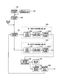
- FIG. 4 is a block diagram showing a configuration of a region division adaptive interpolation filter (RBAIF) according to the prior art.
- the reference image storage unit 101 stores a reference image used for inter-screen prediction.
- the motion vector related information storage unit 102 stores motion vector related information used for inter-screen prediction for an input image and a reference image.
- the predicted image generation unit 103 reads the reference image read from the reference image storage unit 101 and the motion vector related information read from the motion vector related information storage unit 102 as inputs, and uses the reference image and the motion vector related information to perform motion compensation. Based on the inter-screen prediction process, a predicted image for the input image is generated.
- the division region setting unit 104 sets a division position for performing frame division based on a designated order from among division position candidates.
- the prediction error power sum calculation unit 105 receives the two output prediction error powers, and calculates the sum of the two as the prediction error power sum in the frame.
- the minimum value determination unit 106 determines whether or not the prediction error sum calculated by the prediction error power sum calculation unit 105 is smaller than the stored value.
- the prediction error sum, the position information indicating the division position, and the filter coefficients for the two divided areas when divided at the same division position are stored.
- the prediction error power sum storage unit 107 stores the prediction error sum calculated by the prediction error power sum calculation unit 105, the position information indicating the division position, and the filter coefficients for the two divided regions when divided at the same division position.
- the repetition process end determination unit 108 repeats the process until the process is executed for all candidates for the division position.
- the first region prediction error power calculation unit 109 includes a normal equation generation unit 1091, a normal equation solution processing unit 1092, and a prediction error power calculation processing unit 1093.
- the normal equation generation unit 1091 calculates a multiplication coefficient and a bias coefficient constituting the normal equation of the divided area, and generates a normal equation for the divided area.
- the corresponding divided region is a left region when horizontal division is performed in the horizontal direction, and is an upper region when vertical division is performed in the vertical direction.
- the normal equation solution processor 1092 obtains a solution of the normal equation generated by the normal equation generator 1091 and stores it as an interpolation filter coefficient.
- the prediction error power calculation processing unit 1093 calculates the prediction error power when the interpolation filter coefficient calculated by the normal equation solution processing unit 1092 is used.
- the second region prediction error power calculation unit 110 includes a normal equation generation unit 1101, a normal equation solution processing unit 1102, and a prediction error power calculation processing unit 1103.
- the normal equation generation unit 1101 calculates a multiplication coefficient and a bias coefficient constituting the normal equation of the divided area, and generates a normal equation for the divided area.
- the corresponding divided area is a right area when performing horizontal division in the horizontal direction, and is a lower area when performing vertical division in the vertical direction.
- the normal equation solution processing unit 1102 obtains a solution of the normal equation generated by the normal equation generation unit 1101 and stores it as an interpolation filter coefficient.
- the prediction error power calculation processing unit 1103 calculates prediction error power when the interpolation filter coefficient calculated by the normal equation solution processing unit 1102 is used.
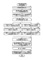
- FIG. 5 is a flowchart showing the operation of the region division adaptive interpolation filter (RBAIF) shown in FIG.
- the predicted image generation unit 103 reads a reference image used for inter-frame prediction from the reference image storage unit 101 (step S1). Subsequently, the predicted image generation unit 103 reads, from the motion vector related information storage unit 102, motion vector related information obtained as a result of performing the motion estimation process using the reference image for the encoding target image (step S2). . Then, based on the motion compensation inter-screen prediction process, a predicted image for the input image is generated (step S3).
- the divided region setting unit 104 sets divided regions and outputs the setting information to the two normal equation generation units 1091 and 1101.
- the normal equation generation unit 1091 calculates a multiplication coefficient and a bias coefficient constituting the normal equation of the set divided region, generates a normal equation for the divided region, and outputs it (step S4).
- the corresponding divided region is a left region when horizontal division is performed in the horizontal direction, and is an upper region when vertical division is performed in the vertical direction.
- the normal equation solution processor 1092 obtains a solution of the normal equation output from the normal equation generator 1091 and stores it as an interpolation filter coefficient (step S5).
- the prediction error power calculation processing unit 1093 calculates and outputs the prediction error power when this interpolation filter coefficient is used (step S6).
- the normal equation generation unit 1101 calculates a multiplication coefficient and a bias coefficient constituting the normal equation of the set divided region, generates a normal equation for the divided region, and outputs it (step S7).
- the corresponding divided area is a right area when performing horizontal division in the horizontal direction, and is a lower area when performing vertical division in the vertical direction.
- the normal equation solution processing unit 1102 calculates a solution of the normal equation output from the normal equation generation unit 1101 and stores it as an interpolation filter coefficient (step S8).
- the prediction error power calculation processing unit 1103 calculates and outputs the prediction error power when this interpolation filter coefficient is used (step S9).
- the prediction error power sum calculation processing unit 105 receives the prediction error power output from the two prediction error power calculation processing units 1093 and 1103, and calculates the sum of the two as the prediction error power sum in the frame. And it memorize
- the minimum value determination unit 106 obtains a division position that gives the minimum value among the prediction error sums stored in the prediction error power sum storage unit 107, and stores filter coefficients for two divided regions when the division is performed at the division position. (Step S11).
- the repetition process end determination unit 108 determines whether or not all the candidates for division positions have been processed, and outputs an instruction to repeat the process to the divided region setting unit 104 if the processing has not been completed for all candidates. Then, when the processing is completed for all candidates, the iterative processing end determination unit 108 obtains a division position that minimizes the prediction error sum, and outputs filter coefficients for the two divided regions when division is performed at the same division position. (Step S12).
- a square area ( ⁇ ⁇ ⁇ pixel) called a segmentation unit (SU) is defined as a minimum unit of area division in a frame.
- a region division adaptive interpolation filter that performs region division using the above SU as a minimum unit and sets an optimal interpolation filter coefficient for each divided region is targeted.
- W ⁇ H [pixel] W ⁇ H [pixel]
- WH / ⁇ 2 SUs are included.
- W / ⁇ division methods including the option of not dividing when the frame is divided into left and right parts in the horizontal direction, and the option of not dividing when the frame is divided into two parts vertically.
- H / ⁇ division methods There are H / ⁇ division methods.
- ⁇ x, y n ⁇ ⁇ ⁇ x ⁇ (n + 1) ⁇ ⁇ 1, m ⁇ ⁇ ⁇ y ⁇ (m + 1) ⁇ ⁇ 1 ⁇ in the frame is denoted as ⁇ (n, m).
- the total sum of prediction error power in a frame is used as a standard for determining the region division of the region division adaptive interpolation filter. It should be noted that the filter coefficient for the rectangular area identified by the four coordinate values (px, py), (px + lx, py), (px, py + ly-1), (px + lx-1, py + ly-1) in the frame.
- the prediction error power when ⁇ (px, py, lx, ly) is used is expressed as E (px, py, lx, ly, ⁇ (px, py, lx, ly)).
- the region division that divides into the left region of x ⁇ n opt ⁇ ⁇ and the right region of n opt ⁇ ⁇ ⁇ x is set as the optimum region division.
- the SU size ⁇ is set to a large value for high-definition video, the increase in the amount of computation described above can be suppressed. On the other hand, there is a possibility that the accuracy of area division is reduced and sufficient prediction performance cannot be obtained. is there.
- the present invention has been made in view of such circumstances, and an area division adaptive interpolation filter capable of reducing the amount of calculation required for selecting an optimum area division while maintaining the prediction performance of the area division adaptive interpolation filter. It is an object of the present invention to provide a video encoding device, a video encoding method, and a video encoding program having a function.
- the moving image encoding apparatus supports region division as an interpolation filter for generating an interpolated pixel value at a decimal pixel position by dividing an area within a frame and adaptively setting an interpolation filter coefficient for each divided region.
- the division region defined by the division position is selected.
- the duplicated calculation processing result is used and only the difference information without duplication is used. There generates an equation for calculating the new calculation.
- the moving image encoding apparatus calculates necessary information for each minimum unit of the area division in advance, and calculates the calculated information as necessary.
- the difference information necessary for use may be calculated.
- the moving picture decoding apparatus may decode the moving picture encoded by the moving picture encoding apparatus.
- the moving image encoding method is an area division that divides an area of a frame as an interpolation filter that generates an interpolation pixel value at a decimal pixel position, and adaptively sets an interpolation filter coefficient for each divided area.
- a video encoding apparatus that performs motion compensation inter-frame prediction corresponding to decimal pixel accuracy using a corresponding adaptive filter, when selecting an optimal division position from candidates of division positions prepared in advance, the division position
- the equation generation step includes an overlapping calculation process in calculating the interpolation filter coefficient in different divided regions. Diverted result, generates an equation for calculating the newly calculated only for non-overlapping differential information.
- the difference information when calculating the difference information, necessary information is calculated in advance for each minimum unit of the area division, and the calculated information is used as necessary.
- the difference information necessary for use may be calculated.
- the moving picture decoding method according to the present invention may decode the moving picture encoded by the moving picture encoding method.
- a moving picture coding program for causing a computer on a moving picture coding apparatus according to the present invention to perform coding processing divides a frame into regions as an interpolation filter for generating an interpolation pixel value at a decimal pixel position.
- an area division adaptive filter that adaptively sets interpolation filter coefficients for each area, motion compensated interframe prediction corresponding to decimal pixel accuracy is performed, and optimal division among candidates of division positions prepared in advance is performed.
- An equation generation step for constructing a linear simultaneous equation for obtaining an interpolation filter coefficient for a divided region defined by the division position when selecting a position, and an equation for obtaining the interpolation filter coefficient by solving the linear simultaneous equation
- a solution processing step is performed by the computer, and the equation generation step is performed in the different divided regions. In calculation for calculating between filter coefficients, diverted duplicate operation result to generate an equation for calculating the newly calculated only for non-overlapping differential information.
- the moving picture decoding program according to the present invention may decode the moving picture encoded by the moving picture encoding program.
- the present invention when calculating filter coefficients for different division shapes in a filter calculation process of an area division-compatible adaptive filter that involves calculation of an optimal division position, it is possible to omit redundant processing and predict performance. The effect that the amount of calculation can be reduced without lowering is obtained.
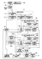
- FIG. 1 It is a block diagram which shows the structure of one Embodiment of this invention. It is a flowchart which shows operation
- RBAIF area division adaptive interpolation filter
- RBAIF area division adaptive interpolation filter
- the principle of operation of the area division adaptive interpolation filter used in the moving picture coding apparatus according to the embodiment of the present invention will be described.
- the present invention focuses on the fact that overlapping processing is included in the filter coefficient calculation method for different division shapes of the region division adaptive interpolation filter, and omitting the calculation of such overlapping processing without reducing the prediction performance. This is intended to reduce the amount of calculation.
- information related to inter-screen prediction (such as the size of a block to be predicted, a motion vector, and a reference image for motion compensation) is shared regardless of the shape of the region division.
- Information related to the inter-screen prediction is referred to as motion vector related information.
- the motion vector related information is, for example, standard H.264. H.264 / AVC is used to interpolate the pixel value at the decimal pixel position using a fixed coefficient interpolation filter, and a motion estimation algorithm (for example, documents “K. P. Lim, G. Sullivan, and T. Wiegand. Text description of joint model reference encoding methods and decoding concealment methods.
- Equations (3) and (6) are modified as follows.
- equations (3) and (6) can be expressed simply as follows.
- the left area is divided into adaptive interpolation.
- the filter coefficient ⁇ (0, 0, kx ⁇ ⁇ , H) of the filter is a solution of the following linear simultaneous equations.
- the filter coefficient ⁇ (kx ⁇ ⁇ , 0, W ⁇ kx ⁇ ⁇ , H) of the area division adaptive interpolation filter in the right area is a solution of the following linear simultaneous equations.
- the linear simultaneous equations are called normal equations. Further, the term on the right side of the normal equation is referred to as a bias coefficient, and the value multiplied by wc i and wc j on the left side is referred to as a multiplication coefficient.
- the filter coefficient ⁇ (kx ⁇ ⁇ , 0, W ⁇ (kx + 1) ⁇ ⁇ , H) of the area division adaptive interpolation filter in the right area is a solution of the following linear simultaneous equations.
- the above is the case of the right region, but also in the case of the left region, by storing the values obtained in the calculation process of Equation (21) as follows, the screen is divided into two regions on the left and right sides. Similarly, when calculating the filter coefficient in the case of dividing into the left region x ⁇ (kx + 2) ⁇ ⁇ and the right region (kx + 2) ⁇ ⁇ ⁇ x, the same calculation can be omitted.
- FIG. 1 is a block diagram showing the configuration of the embodiment.
- the area division adaptive interpolation filter shown in this figure is different from the conventional area division adaptive interpolation filter in that the first area prediction error power calculation section 109 and the second area prediction error power calculation section 110 have a multiplication coefficient storage section 1094. 1104 and bias coefficient storage units 1095 and 1105 are newly provided, and a calculation element storage unit 111 is newly provided.
- the SU autocorrelation coefficient calculation unit 1111 reads a prediction image as an input, calculates SU autocorrelation coefficients for all the SUs (segmentation units) in the frame, and outputs the calculation results to the SU autocorrelation coefficient storage unit 1113.
- the SU cross-correlation calculation unit 1112 reads the encoding target image and the prediction image as inputs, calculates SU cross-correlation coefficients for all SUs in the frame, and outputs the calculation results to the SU cross-correlation coefficient storage unit 1114. To store.
- the normal equation generation unit 1091 reads the multiplication coefficient from the multiplication coefficient storage unit 1094, calculates a difference value between the coefficient and a multiplication coefficient necessary for constructing the normal equation, adds the stored multiplication coefficient and difference value, Output as a multiplication coefficient necessary to construct a normal equation.
- the SU autocorrelation coefficient and the SU cross-correlation coefficient stored in the SU auto-correlation coefficient storage unit 1113 and the SU cross-correlation coefficient storage unit 1114 are read out, and the SU auto-correlation coefficient and the SU cross-correlation coefficient are read out.
- the difference value obtained here is stored in the multiplication coefficient difference value storage unit 1096 so that it can be reused in subsequent processing.
- the normal equation generation unit 1091 reads the bias coefficient from the bias coefficient storage unit 1095, calculates the difference value between the coefficient and the bias coefficient necessary for constructing the normal equation, and adds the stored bias coefficient and difference value. And output as a bias coefficient necessary for constructing a normal equation.
- the SU autocorrelation coefficient and the SU cross-correlation coefficient stored in the SU auto-correlation coefficient storage unit 1113 and the SU cross-correlation coefficient storage unit 1114 are read, and the SU auto-correlation coefficient and the SU cross-correlation coefficient are read out. Set based on the addition of correlation coefficients.
- the difference value obtained here is stored in the bias coefficient difference value storage unit 1097 so that it can be reused in subsequent processing.
- the normal equation generation unit 1091 reads the multiplication coefficient and bias coefficient calculated in this process, and generates a normal equation for the divided area.
- the corresponding divided region is a left region when horizontal division is performed in the horizontal direction, and is an upper region when vertical division is performed in the vertical direction.
- the calculated multiplication coefficient and bias coefficient are stored in the multiplication coefficient storage unit 1094 and the bias coefficient storage unit 1095, respectively.
- the normal equation solution processor 1092 obtains a solution of the normal equation generated by the normal equation generator 1091 and stores it as an interpolation filter coefficient.
- the prediction error power calculation processing unit 1093 reads the encoding target image, the reference image, the motion vector related information, the interpolation filter coefficient calculated by the normal equation solution processing unit 1092, and the prediction error power when the interpolation filter coefficient is used. Is calculated.
- the normal equation generation unit 1101 reads the multiplication coefficient from the multiplication coefficient storage unit 1104, further reads the difference value of the multiplication coefficient from the multiplication coefficient difference value storage unit 1096, subtracts the latter from the former, and is necessary for constructing the normal equation. Output as multiplication coefficient. Further, the normal equation 1101 reads a bias coefficient from the bias coefficient storage unit 1105, further reads a bias coefficient difference value from the bias coefficient difference value storage unit 1097, subtracts the latter from the former, and is necessary for constructing a normal equation. Output as a bias coefficient.
- the multiplication coefficient and the bias coefficient calculated in this process are read to generate a normal equation for the divided area.
- the corresponding divided area is a right area when performing horizontal division in the horizontal direction, and is a lower area when performing vertical division in the vertical direction.
- the calculated multiplication coefficient and bias coefficient are stored in the multiplication coefficient storage unit 1104 and the bias coefficient storage unit 1105, respectively.
- the normal equation solution processing unit 1102 obtains a solution of the normal equation generated by the normal equation generation unit 1101 and stores it as an interpolation filter coefficient.
- the prediction error power calculation processing unit 1103 reads the encoding target image, the reference image, the motion vector related information, and the interpolation filter coefficient calculated by the normal equation solution processing unit 1102 and uses the same interpolation filter coefficient. Is calculated.
- FIG. 2 is a flowchart showing the processing operation of the area division adaptive interpolation filter (RBAIF) shown in FIG.
- the predicted image generation unit 103 reads a reference image used for inter-frame prediction from the reference image storage unit 101 (step S1). Subsequently, the predicted image generation unit 103 reads, from the motion vector related information storage unit 102, motion vector related information obtained as a result of performing the motion estimation process using the reference image for the encoding target image (step S2). . Then, based on the motion compensation inter-screen prediction process, a predicted image for the input image is generated (step S3).
- the SU autocorrelation coefficient calculation unit 1111 reads the generated predicted image as an input, and ⁇ v (n, m, c i ) of Expression (7) for all the SUs (segmentation units) in the frame. , ⁇ h (n, m, c i ), the SU autocorrelation coefficient is calculated, and the calculation result is stored (step S31). Subsequently, the SU cross-correlation coefficient calculating unit 1112 reads the encoding target image and the prediction image as inputs, and ⁇ v (n, m), ⁇ h (n, The SU cross-correlation coefficient is calculated based on the definition of m), and the calculation result is stored (step S32).
- the divided region setting unit 104 sets a divided region, outputs the setting information to the normal equation generation unit 1091, and stores it in the divided position information storage unit 1073.
- Examples of the division method include a method of dividing the screen horizontally into two regions, an upper region and a lower region, or dividing the screen vertically into two regions, a left region and a right region. At this time, information indicating the division position is given separately.
- the procedure for optimizing the filter coefficient for the separation type filter will be described, but the same can be applied to the non-separation type filter.
- the horizontal direction interpolation filter coefficients are derived in the order of the vertical direction interpolation filter coefficients. Of course, this derivation order can be reversed.
- the normal equation generation unit 1091 generates the multiplication coefficient (Av (0, kx ⁇ 1, 0, H / ⁇ 1, c in Expression (19) and Expression (20)) stored in the multiplication coefficient storage unit 1094. i ), Ah (0, kx ⁇ 1, 0, H / ⁇ 1, c j )), and the difference value (equation (19), expression (20 ) ) Is calculated, the stored multiplication coefficient and difference value are added, and output as a multiplication coefficient necessary for constructing the normal equation (step S41).
- the SU autocorrelation coefficient and the SU cross-correlation coefficient stored in the SU auto-correlation coefficient storage unit 1113 and the SU cross-correlation coefficient storage unit 1114 are read, and the SU auto-correlation coefficient and the SU cross-correlation coefficient are read out.
- the difference value obtained here is stored in the multiplication coefficient difference value storage unit 1096 so that it can be reused in subsequent processing.
- the normal equation generation unit 1091 stores the bias coefficient (Bv (0, kx ⁇ 1, 0, H / ⁇ 1) in Expression (19) and Expression (20)) stored in the bias coefficient storage unit 1095, Bh (0, kx ⁇ 1, 0, H / ⁇ 1)) is read, and the difference value of the bias coefficient necessary for the construction of the same coefficient and the normal equation (formula (19), formula (20)) ), And the stored bias coefficient and difference value are added and output as a bias coefficient necessary for constructing the normal equation (step S42).
- the SU autocorrelation coefficient and the SU cross-correlation coefficient stored in the SU auto-correlation coefficient storage unit 1113 and the SU cross-correlation coefficient storage unit 1114 are read, and the SU auto-correlation coefficient and the SU cross-correlation coefficient are read out.
- the difference value obtained here is stored in the bias coefficient difference value storage unit 1097 so that it can be reused in subsequent processing.
- the normal equation generation unit 1091 reads the calculated multiplication coefficient and bias coefficient, and generates Expressions (19) and (20) as normal equations for the divided regions (Step S43).
- the corresponding divided region is a left region when horizontal division is performed in the horizontal direction, and is an upper region when vertical division is performed in the vertical direction.
- the normal equation generation unit 1091 stores the calculated multiplication coefficient and bias coefficient in the multiplication coefficient storage unit 1094 and the bias coefficient storage unit 1095, respectively (step S44).
- the normal equation solution processing unit 1092 obtains a solution of the normal equation generated by the normal equation generation unit 1091 and stores it as an interpolation filter coefficient in the filter coefficient storage unit 1072 (step S5). Subsequently, the prediction error power calculation processing unit 1093 calculates prediction error power when the interpolation filter coefficient calculated by the normal equation solution processing unit 1092 is used (step S6).
- the normal equation generation unit 1101 reads the multiplication coefficient stored in the multiplication coefficient storage unit 1104 and the difference value stored in the multiplication coefficient difference value storage unit 1096 and stores the stored multiplication coefficient (formula (21)) Difference from Av (kx, W / ⁇ -1, 0, H / ⁇ -1, c i ), Ah (kx, W / ⁇ -1, 0, H / ⁇ -1, c j )) in (22) The value is subtracted and output as a multiplication coefficient necessary for constructing a normal equation (step 71).
- the normal equation generation unit 1101 reads the bias coefficient stored in the bias coefficient storage unit 1105 and the difference value stored in the bias coefficient difference value storage unit 1097 and stores the stored bias coefficient (formula (21)) Subtract the difference value from Bv (kx, W / ⁇ -1, 0, H / ⁇ -1), Bh (kx, W / ⁇ -1, 0, H / ⁇ -1)) in (22) A bias coefficient necessary for constructing the equation is output (step S72).
- the normal equation generation unit 1101 reads the calculated multiplication coefficient and bias coefficient, and generates Expression (21) and Expression (22) as a normal equation for the divided region (Step S73).
- the corresponding divided area is a right area when performing horizontal division in the horizontal direction, and is a lower area when performing vertical division in the vertical direction.
- the normal equation generation unit 1101 stores the calculated multiplication coefficient and bias coefficient in the multiplication coefficient storage unit 1104 and the bias coefficient storage unit 1105, respectively (step S74).
- the normal equation solution processing unit 1102 obtains a solution of the normal equation generated by the normal equation generation unit 1101 and stores it as an interpolation filter coefficient in the filter coefficient storage unit 1072 (step S8). Subsequently, the prediction error power calculation processing unit 1103 calculates prediction error power when the interpolation filter coefficient calculated by the normal equation solution processing unit 1102 is used (step S9).
- the prediction error power sum calculation processing unit 105 receives the prediction error power output from the two prediction error power calculation processing units 1093 and 1103, and calculates the sum of the two as the prediction error power sum in the frame. And it memorize
- the minimum value determination unit 106 obtains a division position that gives the minimum value among the prediction error sums stored in the prediction error power sum storage unit 1071, and stores filter coefficients for two divided regions when the division is performed at the same division position. (Step S11).
- the repetition process end determination unit 108 determines whether or not all the candidates for division positions have been processed, and outputs an instruction to repeat the process to the divided region setting unit 104 if the processing has not been completed for all candidates. Then, when the processing is completed for all candidates, the iterative processing end determination unit 108 obtains a division position that minimizes the prediction error sum, and outputs filter coefficients for the two divided regions when division is performed at the same division position. (Step S12).
- FIG. 3 is a block diagram showing a configuration of the moving image transmission system.
- a moving image input unit 1 inputs a moving image captured by a camera or the like.
- the moving image encoding device 2 is an area division corresponding adaptive filter that divides an area within a frame and adaptively sets an interpolation filter coefficient for each divided area as an interpolation filter that generates an interpolation pixel value at a decimal pixel position.
- the motion compensated inter-frame prediction corresponding to the decimal pixel accuracy is performed using the region division adaptive interpolation filter shown in FIG.
- the transmission path 3 transmits the encoded moving image data transmitted from the moving image encoding device 2.
- the moving picture decoding device 4 receives the encoded moving picture data transmitted through the transmission path 3, decodes the encoded moving picture data, and outputs the decoded data.
- the moving image output unit 5 outputs the moving image decoded by the moving image decoding device 4 to a display device or the like.
- the moving image encoding device 2 inputs moving image data via the moving image input unit 1 and performs encoding for each frame of the moving image. At this time, the optimal division position of the image is calculated by the area division adaptive interpolation filter shown in FIG. Then, the moving image encoding device 2 transmits the encoded moving image data to the moving image decoding device 4 via the transmission path 3. The moving image decoding device 4 decodes the encoded moving image data, and displays the moving image on a display device or the like via the moving image output unit 5.
- a frame is divided into regions as an interpolation filter for generating an interpolation pixel value at a decimal pixel position.
- each division position is defined in the process of selecting the optimum division position from among the prepared division position candidates.
- calculating the interpolation filter coefficient for a divided region when a linear simultaneous equation is constructed as a process for calculating the filter coefficient of the filter and the process for solving the equation is used, it is overlapped in the filter coefficient calculation process in different divided regions. The calculation processing is optimized and only the difference information without duplication is newly calculated. In the filter calculation process of the adaptive filter for region division, it is possible to omit duplicate processing when calculating filter coefficients for different division shapes, and to reduce the calculation amount without degrading the prediction performance be able to.
- a program for realizing the functions of the respective processing units in FIG. 1 is recorded on a computer-readable recording medium, and the program recorded on the recording medium is read into a computer system and executed to cope with area division.
- An adaptive filter process may be performed.
- the “computer system” includes an OS and hardware such as peripheral devices.
- the “computer-readable recording medium” refers to a storage device such as a flexible medium, a magneto-optical disk, a portable medium such as a ROM or a CD-ROM, and a hard disk incorporated in a computer system.
- the “computer-readable recording medium” refers to a volatile memory (RAM) in a computer system that becomes a server or a client when a program is transmitted via a network such as the Internet or a communication line such as a telephone line. In addition, those holding programs for a certain period of time are also included.
- RAM volatile memory
- the program may be transmitted from a computer system storing the program in a storage device or the like to another computer system via a transmission medium or by a transmission wave in the transmission medium.
- the “transmission medium” for transmitting the program refers to a medium having a function of transmitting information, such as a network (communication network) such as the Internet or a communication line (communication line) such as a telephone line.
- the program may be for realizing a part of the functions described above. Furthermore, what can implement
- the moving picture coding and moving picture decoding according to the present invention can be applied to an application in which it is indispensable to reduce the amount of calculation required for selecting an optimum area division while maintaining the prediction performance of the area division adaptive interpolation filter.
Landscapes
- Engineering & Computer Science (AREA)
- Multimedia (AREA)
- Signal Processing (AREA)
- Compression Or Coding Systems Of Tv Signals (AREA)
Abstract
Description
本願は、2011年6月13日に、日本に出願された特願2011-131127号に基づき優先権を主張し、その内容をここに援用する。





そして、予測誤差電力算出処理部1093は、この補間フィルタ係数を用いた場合の予測誤差電力を算出して出力する(ステップS6)。
E(0,0,n・Δ,H,η(0,0,n・Δ,H))+E(n・Δ,0,W-n・Δ,H,η(n・Δ,0,W-n・Δ,H))

式(3)及び式(6)を次のように変形する。
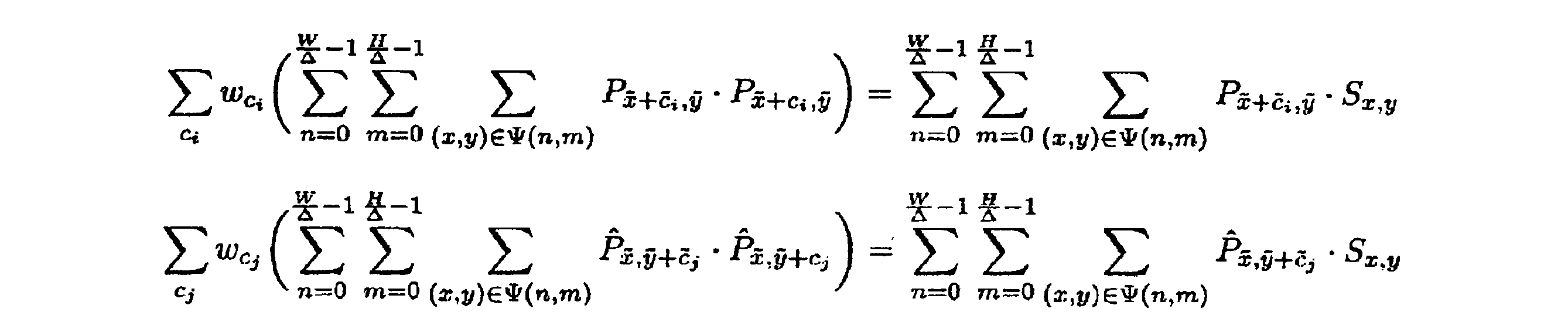
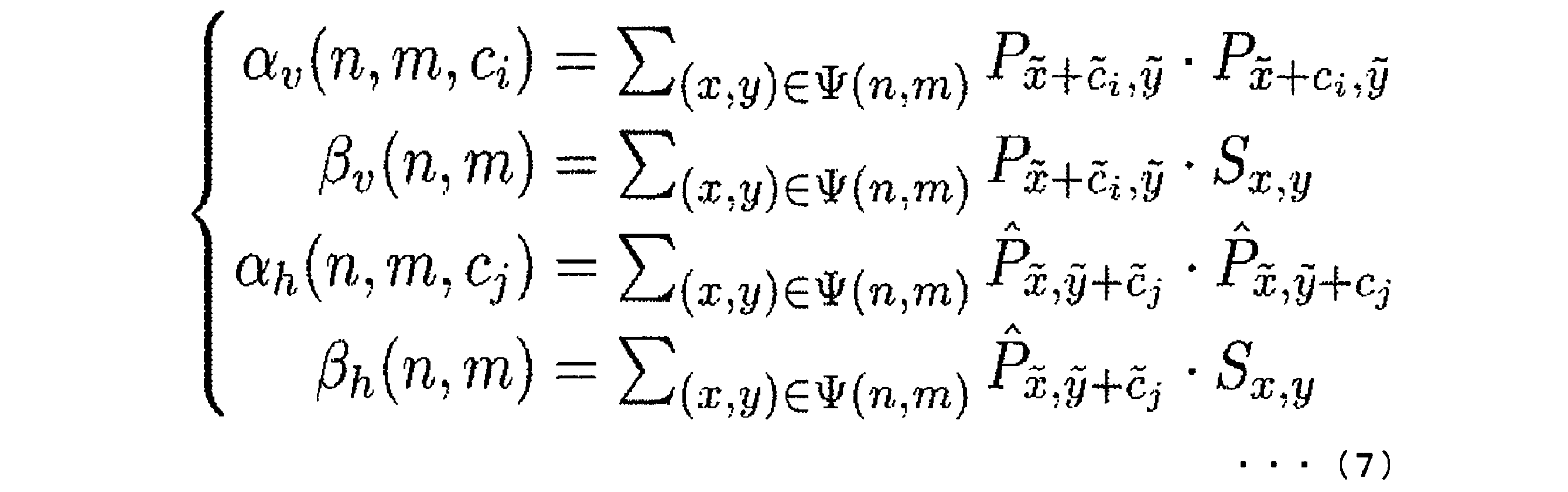
とおくと、式(3)及び式(6)は次のように簡潔に表すことができる。


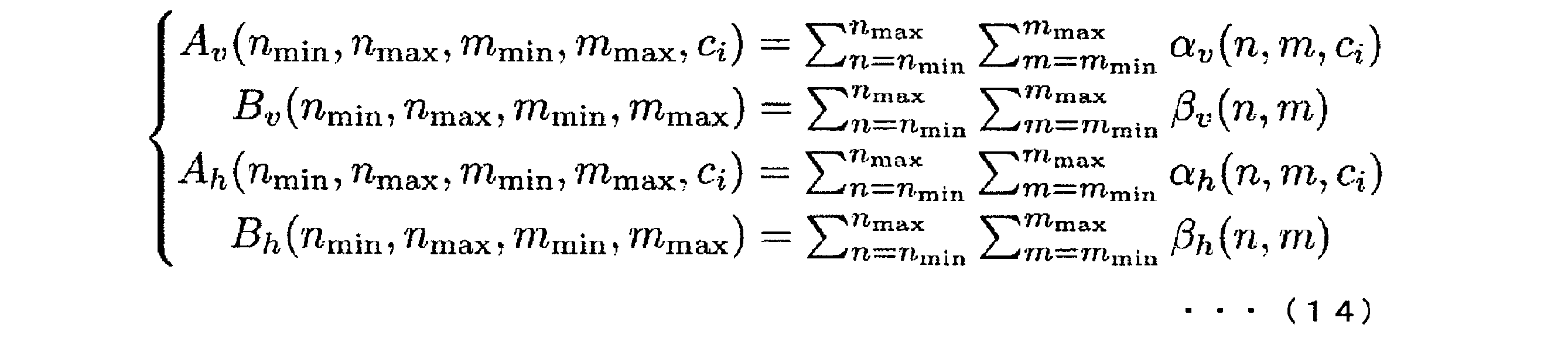
とおくと、左領域の領域分割適応補間フィルタのフィルタ係数η(0,0,kx・Δ,H)を求めるための線形連立方程式は次式となる。


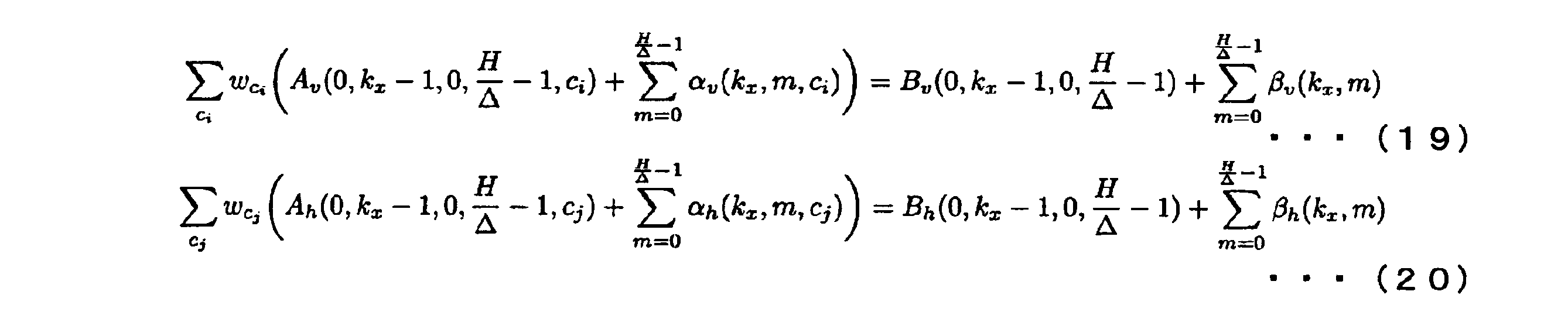






)を算出し、格納されている乗算係数及び差分値を加算し、正規方程式の構築に必要な乗算係数として出力する(ステップS41)。差分値の算出には、SU自己相関係数記憶部1113、SU相互相関係数記憶部1114に格納されたSU自己相関係数、SU相互相関係数を読出し、SU自己相関係数、SU相互相関係数の加算に基づき設定する。ここで求めた差分値は、後続の処理で再利用可能なように乗算係数差分値記憶部1096に格納する。

)を算出し、格納されているバイアス係数及び差分値を加算し、正規方程式の構築に必要なバイアス係数として出力する(ステップS42)。差分値の算出には、SU自己相関係数記憶部1113、SU相互相関係数記憶部1114に格納されたSU自己相関係数、SU相互相関係数を読出し、SU自己相関係数、SU相互相関係数の加算に基づき設定する。ここで求めた差分値は、後続の処理で再利用可能なようにバイアス係数差分値記憶部1097に格納する。
なお、ここでいう「コンピュータシステム」とは、OSや周辺機器等のハードウェアを含むものとする。また、「コンピュータ読み取り可能な記録媒体」とは、フレキシブルディスク、光磁気ディスク、ROM、CD-ROM等の可搬媒体、コンピュータシステムに内蔵されるハードディスク等の記憶装置のことをいう。さらに「コンピュータ読み取り可能な記録媒体」とは、インターネット等のネットワークや電話回線等の通信回線を介してプログラムが送信された場合のサーバやクライアントとなるコンピュータシステム内部の揮発性メモリ(RAM)のように、一定時間プログラムを保持しているものも含むものとする。
2 動画像符号化装置
3 伝送路
4 動画像復号装置
5 動画像出力部
101 参照画像記憶部
102 動きベクトル関連情報記憶部
103 予測画像生成部
104 分割領域設定部
105 予測誤差電力和算出処理部
106 最小値判定部
108 繰返処理終了判定部
109 第一領域予測誤差電力算出部
110 第二領域予測誤差電力算出部
111 演算要素格納部
1071 予測誤差電力和記憶部
1072 フィルタ係数記憶部
1073 分割位置情報記憶部
1091 正規方程式生成部
1092 正規方程式求解処理部、
1093 予測誤差電力算出処理部
1094 乗算係数記憶部、
1095 バイアス係数記憶部、
1096 乗算係数差分値記憶部
1097 バイアス係数差分値記憶部
1101 正規方程式生成部
1102 正規方程式求解処理部
1103 予測誤差電力算出処理部
1104 乗算係数記憶部
1105 バイアス係数記憶部
1111 SU自己相関係数算出部
1112 SU相互相関係数算出部
1113 SU自己相関係数記憶部
1114 SU相互相関係数記憶部
Claims (8)
- 小数画素位置の補間画素値を生成する補間フィルタとして、フレーム内を領域分割し、分割された領域毎に補間フィルタの係数を適応的に設定する領域分割対応適応フィルタを用いて、小数画素精度に対応した動き補償フレーム間予測を行う動画像符号化装置であって、
予め用意された分割位置の候補の中から最適な分割位置を選択する際に、分割位置により規定される分割領域に対する補間フィルタ係数を求めるための線形連立方程式を構築する方程式生成部と、
前記線形連立方程式を求解することにより前記補間フィルタ係数を求める方程式求解処理部とを備え、
前記方程式生成部は、異なる分割領域における前記補間フィルタ係数を算出する演算において、重複した演算処理結果を流用し、重複のない差分情報のみについて新たに演算によって算出する方程式を生成する動画像符号化装置。 - 前記差分情報を算出する際に、前記領域分割の最小単位毎に必要な情報を予め算出しておき、予め算出しておいた情報を必要に応じて使用して必要な前記差分情報を算出する請求項1に記載の動画像符号化装置。
- 請求項1に記載の動画像符号化装置によって符号化された動画像を復号する動画像復号装置。
- 小数画素位置の補間画素値を生成する補間フィルタとして、フレーム内を領域分割し、分割された領域毎に補間フィルタの係数を適応的に設定する領域分割対応適応フィルタを用いて、小数画素精度に対応した動き補償フレーム間予測を行う動画像符号化装置における動画像符号化方法であって、
予め用意された分割位置の候補の中から最適な分割位置を選択する際に、分割位置により規定される分割領域に対する補間フィルタ係数を求めるための線形連立方程式を構築する方程式生成ステップと、
前記線形連立方程式を求解することにより前記補間フィルタ係数を求める方程式求解処理ステップとを有し、
前記方程式生成ステップは、異なる分割領域における前記補間フィルタ係数を算出する演算において、重複した演算処理結果を流用し、重複のない差分情報のみについて新たに演算によって算出する方程式を生成する動画像符号化方法。 - 前記差分情報を算出する際に、前記領域分割の最小単位毎に必要な情報を予め算出しておき、予め算出しておいた情報を必要に応じて使用して必要な前記差分情報を算出する請求項4に記載の動画像符号化方法。
- 請求項4に記載の動画像符号化方法によって符号化された動画像を復号する動画像復号方法。
- 小数画素位置の補間画素値を生成する補間フィルタとして、フレーム内を領域分割し、分割された領域毎に補間フィルタの係数を適応的に設定する領域分割対応適応フィルタを用いて、小数画素精度に対応した動き補償フレーム間予測を行う動画像符号化装置上のコンピュータに符号化処理を行わせる動画像符号化プログラムであって、
予め用意された分割位置の候補の中から最適な分割位置を選択する際に、分割位置により規定される分割領域に対する補間フィルタ係数を求めるための線形連立方程式を構築する方程式生成ステップと、
前記線形連立方程式を求解することにより前記補間フィルタ係数を求める方程式求解処理ステップとを前記コンピュータに行わせ、
前記方程式生成ステップは、異なる分割領域における前記補間フィルタ係数を算出する演算において、重複した演算処理結果を流用し、重複のない差分情報のみについて新たに演算によって算出する方程式を生成する動画像符号化プログラム。 - 請求項7に記載の動画像符号化プログラムによって符号化された動画像を復号する動画像復号プログラム。
Priority Applications (7)
| Application Number | Priority Date | Filing Date | Title |
|---|---|---|---|
| CN201280028428.6A CN103621089A (zh) | 2011-06-13 | 2012-06-12 | 动态图像编码装置、动态图像解码装置、动态图像编码方法、动态图像解码方法、动态图像编码程序及动态图像解码程序 |
| US14/125,165 US20140119453A1 (en) | 2011-06-13 | 2012-06-12 | Video encoding device, video decoding device, video encoding method, video decoding method, video encoding program, and video decoding program |
| RU2013154600/08A RU2013154600A (ru) | 2011-06-13 | 2012-06-12 | Устройство кодирования видео, устройство декодирования видео, способ кодирования видео, способ декодирования видео, программа кодирования видео и программа декодирования видео |
| EP12800560.0A EP2709362A4 (en) | 2011-06-13 | 2012-06-12 | VIDEO ENCODER, VIDEO ENCODER, VIDEO ENCODER, VIDEO ENCODER, VIDEO ENCODER, AND VIDEO ENCODER |
| CA 2838978 CA2838978A1 (en) | 2011-06-13 | 2012-06-12 | Video encoding device, video decoding device, video encoding method, video decoding method, video encoding program, and video decoding program |
| BR112013031755A BR112013031755A2 (pt) | 2011-06-13 | 2012-06-12 | dispositivo de codificação de vídeo, dispositivo de decodificação de vídeo, método de codificação de vídeo, método de decodificação de vídeo, programa de codificação de vídeo, e programa de decodificação de vídeo |
| KR20137032535A KR20140007076A (ko) | 2011-06-13 | 2012-06-12 | 동화상 부호화 장치, 동화상 복호 장치, 동화상 부호화 방법, 동화상 복호 방법, 동화상 부호화 프로그램 및 동화상 복호 프로그램 |
Applications Claiming Priority (2)
| Application Number | Priority Date | Filing Date | Title |
|---|---|---|---|
| JP2011131127A JP5552093B2 (ja) | 2011-06-13 | 2011-06-13 | 動画像符号化装置、動画像符号化方法及び動画像符号化プログラム |
| JP2011-131127 | 2011-06-13 |
Publications (1)
| Publication Number | Publication Date |
|---|---|
| WO2012173125A1 true WO2012173125A1 (ja) | 2012-12-20 |
Family
ID=47357112
Family Applications (1)
| Application Number | Title | Priority Date | Filing Date |
|---|---|---|---|
| PCT/JP2012/065045 Ceased WO2012173125A1 (ja) | 2011-06-13 | 2012-06-12 | 動画像符号化装置、動画像復号装置、動画像符号化方法、動画像復号方法、動画像符号化プログラム及び動画像復号プログラム |
Country Status (10)
| Country | Link |
|---|---|
| US (1) | US20140119453A1 (ja) |
| EP (1) | EP2709362A4 (ja) |
| JP (1) | JP5552093B2 (ja) |
| KR (1) | KR20140007076A (ja) |
| CN (1) | CN103621089A (ja) |
| BR (1) | BR112013031755A2 (ja) |
| CA (1) | CA2838978A1 (ja) |
| RU (1) | RU2013154600A (ja) |
| TW (1) | TW201306593A (ja) |
| WO (1) | WO2012173125A1 (ja) |
Families Citing this family (6)
| Publication number | Priority date | Publication date | Assignee | Title |
|---|---|---|---|---|
| WO2014078068A1 (en) * | 2012-11-13 | 2014-05-22 | Intel Corporation | Content adaptive transform coding for next generation video |
| WO2019009590A1 (ko) | 2017-07-03 | 2019-01-10 | 김기백 | 추가 영역을 포함하는 분할 단위를 이용한 영상 복호화 방법 및 장치 |
| CN116248863B (zh) * | 2017-07-03 | 2025-11-25 | 汉阳大学校产学协力团 | 利用包含追加区域的分割单位的影像解码方法以及装置 |
| EP3741121B1 (en) | 2018-02-14 | 2024-09-25 | Huawei Technologies Co., Ltd. | Adaptive interpolation filter |
| CN110519652B (zh) | 2018-05-22 | 2021-05-18 | 华为软件技术有限公司 | Vr视频播放方法、终端及服务器 |
| WO2026012044A1 (en) * | 2024-07-12 | 2026-01-15 | Mediatek Inc. | Method and apparatus of intra estimation region and intra extrapolated region for dip merge mode and eip merge mode in video coding |
Citations (1)
| Publication number | Priority date | Publication date | Assignee | Title |
|---|---|---|---|---|
| JP2011131127A (ja) | 2009-12-22 | 2011-07-07 | Toshio Konuma | 廃棄有機物の低温磁気分解処理装置 |
Family Cites Families (6)
| Publication number | Priority date | Publication date | Assignee | Title |
|---|---|---|---|---|
| WO2007116551A1 (ja) * | 2006-03-30 | 2007-10-18 | Kabushiki Kaisha Toshiba | 画像符号化装置及び画像符号化方法並びに画像復号化装置及び画像復号化方法 |
| EP1983759A1 (en) * | 2007-04-19 | 2008-10-22 | Matsushita Electric Industrial Co., Ltd. | Estimation of separable adaptive interpolation filters for hybrid video coding |
| EP2048886A1 (en) * | 2007-10-11 | 2009-04-15 | Panasonic Corporation | Coding of adaptive interpolation filter coefficients |
| EP2141927A1 (en) * | 2008-07-03 | 2010-01-06 | Panasonic Corporation | Filters for video coding |
| KR102033025B1 (ko) * | 2009-07-07 | 2019-10-16 | 톰슨 라이센싱 | 영역 기반 필터에 대해서 협력적 분할 부호화하는 방법 및 장치 |
| US20130028538A1 (en) * | 2011-07-29 | 2013-01-31 | Simske Steven J | Method and system for image upscaling |
-
2011
- 2011-06-13 JP JP2011131127A patent/JP5552093B2/ja active Active
-
2012
- 2012-06-11 TW TW101120877A patent/TW201306593A/zh unknown
- 2012-06-12 BR BR112013031755A patent/BR112013031755A2/pt not_active IP Right Cessation
- 2012-06-12 US US14/125,165 patent/US20140119453A1/en not_active Abandoned
- 2012-06-12 CN CN201280028428.6A patent/CN103621089A/zh active Pending
- 2012-06-12 EP EP12800560.0A patent/EP2709362A4/en not_active Withdrawn
- 2012-06-12 WO PCT/JP2012/065045 patent/WO2012173125A1/ja not_active Ceased
- 2012-06-12 KR KR20137032535A patent/KR20140007076A/ko not_active Ceased
- 2012-06-12 CA CA 2838978 patent/CA2838978A1/en not_active Abandoned
- 2012-06-12 RU RU2013154600/08A patent/RU2013154600A/ru not_active Application Discontinuation
Patent Citations (1)
| Publication number | Priority date | Publication date | Assignee | Title |
|---|---|---|---|---|
| JP2011131127A (ja) | 2009-12-22 | 2011-07-07 | Toshio Konuma | 廃棄有機物の低温磁気分解処理装置 |
Non-Patent Citations (3)
| Title |
|---|
| MATSUO,S. ET AL.: "CE3: Region-based adaptive interpolation filter", JOINT COLLABORATIVE TEAM ON VIDEO CODING (JCT-VC)OF ITU-T SG16 WP3 AND ISO/IEC JTC1/SC29/WG11 5TH MEETING JCTVC-E078, 18 March 2011 (2011-03-18), XP030048157 * |
| S. WITTMANN; T. WEDI: "Separable adaptive interpolation filter for video coding", IEEE INTERNATIONAL CONFERENCE ON IMAGE PROCESSING, 2008, pages 2500 - 2503 |
| See also references of EP2709362A4 |
Also Published As
| Publication number | Publication date |
|---|---|
| BR112013031755A2 (pt) | 2016-12-13 |
| CN103621089A (zh) | 2014-03-05 |
| EP2709362A4 (en) | 2014-09-24 |
| TW201306593A (zh) | 2013-02-01 |
| KR20140007076A (ko) | 2014-01-16 |
| EP2709362A1 (en) | 2014-03-19 |
| JP2013005020A (ja) | 2013-01-07 |
| JP5552093B2 (ja) | 2014-07-16 |
| CA2838978A1 (en) | 2012-12-20 |
| US20140119453A1 (en) | 2014-05-01 |
| RU2013154600A (ru) | 2015-07-20 |
Similar Documents
| Publication | Publication Date | Title |
|---|---|---|
| JP7335315B2 (ja) | 画像予測方法および関連装置 | |
| CN110581996B (zh) | 子块解码器侧运动矢量细化 | |
| KR101369746B1 (ko) | 적응적 보간 필터를 이용한 영상 부호화, 복호화 방법 및장치 | |
| JP5833757B2 (ja) | 画像符号化方法、画像復号方法、画像符号化装置、画像復号装置、画像符号化プログラム、画像復号プログラム及び記録媒体 | |
| CN114073087B (zh) | 基于矩阵的内预测 | |
| JP5552092B2 (ja) | 動画像符号化装置、動画像符号化方法及び動画像符号化プログラム | |
| JP5552093B2 (ja) | 動画像符号化装置、動画像符号化方法及び動画像符号化プログラム | |
| CN101816183A (zh) | 使用子像素运动估计对图像进行帧间预测编码/解码的方法和设备 | |
| US20130003841A1 (en) | Joint sub-pixel interpolation filter for temporal prediction | |
| JP5649524B2 (ja) | 映像符号化方法,装置,映像復号方法,装置およびそれらのプログラム | |
| EP2704434B1 (en) | Method and device for encoding video image, method and device for decoding video image, and program therefor | |
| KR20110015625A (ko) | 움직임 보상 보간 및 참조 픽쳐 필터링에 대한 국부적 적응형 필터링을 위한 방법 및 장치 | |
| CN101632306B (zh) | 用于运动补偿预测视频编码和解码的自适应内插方法和系统 | |
| JP2011082725A (ja) | 映像符号化方法,映像符号化装置,映像復号方法,映像復号装置,映像符号化・復号方法,およびプログラム | |
| JP5762243B2 (ja) | 映像符号化方法,装置,映像復号方法,装置およびそれらのプログラム | |
| KR101690253B1 (ko) | 영상 처리 장치 및 그 방법 | |
| CN111903132A (zh) | 图像处理装置和方法 | |
| CN114982228A (zh) | 帧间预测方法、编码器、解码器以及计算机存储介质 | |
| KR101601848B1 (ko) | 인터 예측 프레임 생성장치 및 그 생성방법, 및 거기에 이용되는 참조 프레임 보간장치 및 그 방법 |
Legal Events
| Date | Code | Title | Description |
|---|---|---|---|
| 121 | Ep: the epo has been informed by wipo that ep was designated in this application |
Ref document number: 12800560 Country of ref document: EP Kind code of ref document: A1 |
|
| ENP | Entry into the national phase |
Ref document number: 20137032535 Country of ref document: KR Kind code of ref document: A |
|
| WWE | Wipo information: entry into national phase |
Ref document number: 2012800560 Country of ref document: EP |
|
| ENP | Entry into the national phase |
Ref document number: 2838978 Country of ref document: CA |
|
| WWE | Wipo information: entry into national phase |
Ref document number: 14125165 Country of ref document: US |
|
| NENP | Non-entry into the national phase |
Ref country code: DE |
|
| ENP | Entry into the national phase |
Ref document number: 2013154600 Country of ref document: RU Kind code of ref document: A |
|
| REG | Reference to national code |
Ref country code: BR Ref legal event code: B01A Ref document number: 112013031755 Country of ref document: BR |
|
| ENP | Entry into the national phase |
Ref document number: 112013031755 Country of ref document: BR Kind code of ref document: A2 Effective date: 20131210 |