WO2012173136A1 - ゴルフクラブ - Google Patents
ゴルフクラブ Download PDFInfo
- Publication number
- WO2012173136A1 WO2012173136A1 PCT/JP2012/065102 JP2012065102W WO2012173136A1 WO 2012173136 A1 WO2012173136 A1 WO 2012173136A1 JP 2012065102 W JP2012065102 W JP 2012065102W WO 2012173136 A1 WO2012173136 A1 WO 2012173136A1
- Authority
- WO
- WIPO (PCT)
- Prior art keywords
- hosel
- shaft
- hole
- shaft insertion
- adapter
- Prior art date
- Legal status (The legal status is an assumption and is not a legal conclusion. Google has not performed a legal analysis and makes no representation as to the accuracy of the status listed.)
- Ceased
Links
Images

Classifications
-
- A—HUMAN NECESSITIES
- A63—SPORTS; GAMES; AMUSEMENTS
- A63B—APPARATUS FOR PHYSICAL TRAINING, GYMNASTICS, SWIMMING, CLIMBING, OR FENCING; BALL GAMES; TRAINING EQUIPMENT
- A63B60/00—Details or accessories of golf clubs, bats, rackets or the like
- A63B60/50—Details or accessories of golf clubs, bats, rackets or the like with through-holes
-
- A—HUMAN NECESSITIES
- A63—SPORTS; GAMES; AMUSEMENTS
- A63B—APPARATUS FOR PHYSICAL TRAINING, GYMNASTICS, SWIMMING, CLIMBING, OR FENCING; BALL GAMES; TRAINING EQUIPMENT
- A63B53/00—Golf clubs
- A63B53/02—Joint structures between the head and the shaft
Definitions
- This invention relates to the golf club which attaches a shaft to the hosel hole of a hosel part via an adapter.
- Patent Document 1 Japanese Patent Laid-Open No. 2002-153574
- Patent Document 2 Japanese Patent Laid-Open No. 2005-270402. Is known.
- Patent Document 1 the insert is rotated so that the loft angle and the like can be adjusted, and the locking member is pressed against a plurality of depressions provided on the side surface of the insert to stop the rotation. For this reason, since a shearing load is repeatedly applied to the locking member in particular, there is a fear that the club head is not sufficiently fixed around the shaft axis.
- a golf club of the present invention for solving the above-described problems has a shaft, a shaft insertion portion provided with a shaft insertion hole for fixing the shaft at one end, and a central axis of the shaft insertion portion at the other end.
- An adapter having a fixing portion provided integrally with being shifted and having a recess provided in at least a part of the peripheral wall surface, a hosel hole into which the adapter is inserted, and a position corresponding to the recess of the fixing portion from the hosel outer wall
- a head having a hosel portion having a through hole extending to the hosel hole, and a shaft slip-off preventing means that presses the concave portion through the through hole are provided.
- the fixing portion provided integrally with the shaft insertion portion of the adapter is inserted into the lower portion of the hosel hole to suppress the rotation of the club head around the shaft. Further, since the escape preventing means presses the concave portion provided on the wall surface of the fixed portion through the through hole, the shaft does not come out of the hosel hole. Since the impact load applied at the time of hitting the ball is smaller in the removal direction than in the rotation direction around the shaft, the removal prevention means can be made smaller. Moreover, since the shaft and the adapter are fixed and attached to another club head, both the head and the shaft can be reused.
- the golf club of this embodiment includes a shaft made of a tubular body in which fiber reinforced resin prepregs are laminated, a metallic tubular body, or a tubular body formed by combining them, and a club head is attached to the tip of the shaft.
- a grip made mainly of natural rubber or synthetic rubber is attached to the other end.
- the club head may be an iron type or a wood type, and is formed by casting or forging with an iron-based alloy such as stainless steel, or a metal material such as titanium or titanium alloy.
- the club head may be made of a single material or may be formed by joining a plurality of materials, but a hosel hole for receiving an adapter is provided in the hosel part.
- a wood head having a hollow portion formed of an outer shell and provided with an inner hosel such as a metal pipe, a metal block or the like is welded to the lower end of the inner hosel, or a hole is drilled in a rod body.
- an inner hosel such as a metal pipe, a metal block or the like is welded to the lower end of the inner hosel, or a hole is drilled in a rod body.
- the hosel is further provided with a through hole that connects the outer wall of the hosel to the lower stage of the hosel hole.
- the adapter can be made of metal material such as stainless steel, titanium alloy, aluminum alloy, engineering plastic, fiber reinforced resin, etc., but it is more desirable to use a metal material with excellent fatigue characteristics. It is desirable that the shaft insertion portion and the fixing portion are integrally formed, but a protrusion is provided at an end portion where the shaft insertion portion does not open, and a hole corresponding to the protrusion is provided in a separate fixing portion so that the shaft insertion portion You may couple
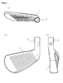
- FIG. 1 is a schematic explanatory view of a club head 1 of the present invention
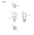
- FIG. 2 is a schematic explanatory view of an adapter 3 attached to a hosel portion 2 of the club head 1.
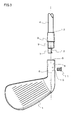
- the adapter 3 fixedly integrated with the tip of the shaft 4 is inserted into the hosel hole 5.
- the lower stage 6 of the hosel hole 5 fits the fixing part 7 of the adapter 3
- the upper stage 8 of the hosel hole 5 fits the shaft insertion part 9 of the adapter 3.
- the shaft 4 and the adapter 3 and the shaft insertion portion 9 and the central axis of the hosel hole 5 coincide with each other.
- the lower stage 6 of the hosel hole 5 and the axis of the fixing part 7 of the adapter 3 also coincide with each other, but the shaft insertion part 9 and the axis of the fixing part 7 do not coincide with each other.
- the removal preventing means 11 presses the surface of the fixing portion 7 on which the concave portion 12 is formed through the through hole 10 that reaches the lower stage 6 of the hosel hole 5 from the hosel outer wall.
- the slip prevention means 11 stays in the through hole 10 by a screw or the like provided in the through hole 10, so that the shaft 4 does not come out of the hosel hole 5.
- FIG. 4 is an example of the adapter 3 according to the present invention.
- the shaft insertion portion 9 having the shaft insertion hole 13 and the fixed portion 7 having an axis Z2 different from the axis Z1 of the shaft insertion portion 9 and provided integrally with the shaft insertion portion 9 are configured.
- axis Z1 of the shaft insertion portion 9 and the axis Z2 of the fixed portion 7 are provided in parallel to facilitate the processing of the hosel hole 5.
- the shaft insertion portion 9 has a cylindrical shape with a diameter D1 of 10.6 to 11.0 mm and a length L1 of 33 mm, and the fixing portion has a diameter D2 of 7.0 to 7.5 mm and a length L2 of 9 mm.
- the cylinders are formed in a cylindrical shape of 0.0 to 14.0 mm, and both cylinders are provided so that one point on the outer periphery thereof is in contact with each other.
- the axis Z1 of the shaft insertion portion 9 and the axis Z2 of the fixing portion 7 are shifted by 1.7 mm in parallel. Yes.
- the fixing portion 7 on the opposite side of the contact point is provided with a recess 12 that gradually becomes deeper toward the shaft insertion portion 9 side.
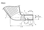
- FIG. 5 is an example of the hosel part 2 in the club head of the present invention.
- the above-described adapter 3 is inserted with the shaft insertion portion 9 and the fixing portion 7 to form a hosel hole 5 composed of an upper stage 8 and a lower stage 6 that are fitted into the shaft insertion part 9 and the fixing part 7 respectively.
- a through hole 10 extending from the lower stage 6 of the hosel hole 5 to the outer wall of the hosel is provided.
- the prevention means 11 presses the recess 12 provided on the side wall of the fixing portion 7 of the adapter 3, and the adapter 3 Do not remove from the hole 5.
- the removal preventing means 11 is detachable, and the adapter 3 can be removed from the hosel hole 5 by removing from the through hole 10.
- the upper stage 8 of the hosel hole 5 is a hole having a diameter D3 of 11.0 to 11.4 mm and a depth L3 of 10.5 to 15.5 mm, and the shaft insertion portion 9 excluding the taper portion can be inserted.
- the lower stage 6 of the hosel hole 5 has a diameter D4 of 7.5 to 8.0 mm and a depth L4 of 9.0 to 14.0 mm so that the adapter 3 can be inserted in a removable state.
- the shaft assembly allowance L1 ' was 25.0 to 27.0 mm.
- the hosel length L5 was 48.0 mm to 63.0 mm.
- the hosel length L5 indicates the distance from the point where the imaginary line on the shaft axis intersects the heel to the upper end of the hosel.
- a screw is provided in a part of the through hole 10 and a bolt is used as the removal preventing means 11.
- the bolt was a stainless steel screw so that it could withstand repeated shear loads.
- the center of gravity of the club head 1 and the center of gravity of the product head corresponding to the club head 1 are increased in order to increase the accuracy as a fitting tool.
- the mass on the heel side is increased by the weight of the adapter 3, so that the center of gravity of the heel is larger than that of the product head.
- the center of gravity is displaced between the product head and the club head 1.
- the weight of the adapter 3 is reduced by adopting a titanium material or an aluminum alloy, and the weight of the hosel portion of the club head 1 is reduced.
- the position of the center of gravity of the club head 1 corresponding to the product head is substantially the same.
- the hosel of the product head corresponding to the club head 1 is cut by a predetermined length, and the hosel length after this cutting is set as the hosel length L5 of the club head 1.
- the machining allowance (mass) of the shaft hole of the club head 1 is the same as the machining allowance in the product head.
- the hosel length L5 (48.0 mm to 63.0 mm) and the shaft assembling allowance L1 ′ (25.0 mm to 27.0 mm) of the above-described embodiment are the product heads having a hosel length of 55.0 mm to 70.0 mm. Therefore, it is possible to further improve the fitting accuracy when the golf club according to the present invention is used as a custom fitting club.
- the hosel length L5 is more preferably in the above range from the viewpoint of ensuring the strength of the adapter 3 and the club head 1.
- a method of attaching the club head 1 and the shaft 4 of the golf club of the present invention will be described.
- the tip of the shaft 4 is fixed to the shaft insertion hole 13 of the adapter 3 by adhesion or the like.
- the ball 3 can be hit as a normal golf club by inserting the adapter 3 with the shaft 4 into the hosel hole 5 and attaching the slip prevention means 11 through the through hole 10 provided in the hosel.
- the club head 1 and the shaft 4 can be easily attached and detached, and both the club head and the shaft can be reused.
- the rotation around the shaft axis of 1 can be stopped.
- the slip-off prevention member 11 presses the inclined surface of the recess 12 to press the fixing portion 7 against the wall surface of the hosel hole 5 and away from the shaft insertion portion 9 (from the upper stage 8 to the lower stage 6 of the hosel hole 5).
- a force can be applied to the fixing portion 7 in the direction of heading. Accordingly, the adapter 3 can be fixed to the hosel portion 2 of the club head 1 and the adapter 3 can be pushed into the hosel portion 2.
- the surface of the adapter 3 positioned around the shaft insertion portion 9 can be pressed against the end surface positioned around the opening of the hosel portion 2, and the adapter 3 is attached to the hosel portion 2 with an inclination. Can be effectively suppressed, and the generation of gaps can also be effectively suppressed.
- the fixing portion 7 is eccentric with respect to the central axis of the shaft insertion portion 9 so that the outer periphery of the shaft insertion portion 9 and the outer periphery of the fixing portion 7 partially overlap each other.
- the recess 12 is formed on the side (outside: eccentric side) opposite to the side where the outer periphery of the shaft insertion portion 9 and the outer periphery of the fixing portion 7 are in contact with each other (inner side: the central axis side of the shaft insertion portion 9) It is provided on the side wall of the fixed portion 7.
- the hosel hole 5 includes an upper stage 8 adapted to the shaft insertion part 9 and a lower stage 6 adapted to the fixing part 7.
- the hosel part 2 further includes a wall part 20 that defines a part of the lower end of the upper stage 8, a part of the upper end of the lower stage 6, and can contact the tip of the shaft insertion part 9. For this reason, when attaching the adapter 3 to the hosel part 2, a part of end surface of the shaft insertion part 9 can be made to contact the wall part 20, and the adapter 3 can be positioned.
- the prevention means 11 can be mounted. This can also contribute to suppressing the inclination of the adapter 3 and reducing the gap between the hosel end and the adapter 3.
- examples of the disconnection preventing means 11 include a fixing member having a screw portion such as a bolt.
- the prevention means 11 is prevented from coming out of the through hole 10. Can be screwed.
- the removal preventing means 11 can be firmly attached to the hosel portion 2 by increasing the length of the wall portion 20 as much as possible. For this reason, the adapter 3 can be prevented from coming off.
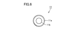
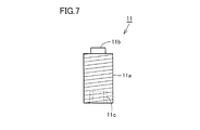
- the drop prevention means 11 in this modification has a main body part 11a, a projection part 11b, and a concave part 11c.
- the main body 11a has a substantially cylindrical shape, but any other shape is adopted as long as it includes a cylindrical portion having a threaded portion formed on the outer peripheral surface. can do. Screws are formed on the outer peripheral surface of the main body 11a.
- a protrusion 11b is provided at the tip of the main body 11a.
- the protrusion 11b any shape can be selected as long as it has a pressing surface capable of pressing the recess 12 on the axial end surface (upper surface).
- the protrusion 11b has a substantially cylindrical shape.
- the protrusion 11b protrudes in the axial direction from the tip of the main body 11a.
- the protruding portion 11b has a smaller diameter than the main body portion 11a.
- the protrusion 11b functions as a pressing portion that presses the adapter 3.
- the contact area with the adapter 3 can be made small. Thereby, the pushing force per unit area can be increased, and the adapter 3 can be firmly fixed to the hosel part 2 with a small force.
- the recess 11c is for inserting a jig such as a hexagon stick wrench for rotating the drop prevention means 11.
- the inner wall of the recess 11c has a shape corresponding to the outer shape of the jig, for example, a hexagonal planar shape.
- the adapter 3 is preferably formed of a single material such as titanium or a titanium alloy, but in the wood type club head 1, the adapter 3 is preferably formed of a composite metal material.
- the main body of the adapter 3 is made of an aluminum alloy and a member made of stainless steel such as SUS304 is attached to the surface of the recess 12.
- stainless steel is used only at that part. Is due to.
- the length L2 of the fixing portion 7 is 9.5 mm
- the depth of the upper stage of the hosel hole (Corresponding to L3 in FIG. 5) may be 26 mm
- the depth of the lower stage of the hosel hole (corresponding to L4 in FIG. 5) may be 12 mm.
Landscapes
- Health & Medical Sciences (AREA)
- General Health & Medical Sciences (AREA)
- Physical Education & Sports Medicine (AREA)
- Golf Clubs (AREA)
Abstract
Description
本実施形態のゴルフクラブは、繊維強化樹脂のプリプレグを積層した管状体や金属製の管状体、あるいはそれらを複合して形成された管状体からなるシャフトを備え、このシャフトの先端にクラブヘッドを取付け、他端に天然ゴムや合成ゴムを主材料としたグリップが取付けられる。
2 ホーゼル部
3 アダプター
4 シャフト
5 ホーゼル孔
6 下段
7 固定部
8 上段
9 シャフト挿入部
10 貫通孔
11 抜け防止手段
11a 本体部
11b 突起部
11c 凹部
12 凹部
13 シャフト挿入孔
20 壁部
Claims (6)
- シャフト(4)と、
一端に前記シャフト(4)を固着するシャフト挿入孔(13)が設けられたシャフト挿入部(9)を有し、他端に前記シャフト挿入部(9)の中心軸とずれて一体的に設けられ、かつ少なくとも周壁面の一部に凹部(12)が設けられた固定部(7)を有するアダプター(3)と、
前記アダプター(3)を挿入するホーゼル孔(5)と前記固定部(7)の前記凹部(12)に対応する位置にホーゼル外壁から前記ホーゼル孔(5)まで延びる貫通孔(10)を有するホーゼル部(2)を有するクラブヘッド(1)と、
前記貫通孔(10)を通り、前記凹部(12)を押圧するシャフト(4)の抜け防止手段(11)とを備えた、ゴルフクラブ。 - 前記凹部(12)の底面において前記抜け防止手段(11)が当接される部分に、シャフト挿入部(9)側に近付くに従い深くなるように傾斜した傾斜面が設けられている、請求項1に記載のゴルフクラブ。
- 前記固定部(7)は、前記シャフト挿入部(9)の中心軸に対し偏心した位置に設けられ、
前記凹部(12)は、前記シャフト挿入部(9)の中心軸側に位置する前記固定部(7)の側壁に設けられている、請求項1に記載のゴルフクラブ。 - 前記ホーゼル孔(5)は、前記シャフト挿入部(9)に適合する上段(8)と、前記固定部(7)に適合する下段(6)とを含み、
前記ホーゼル部(2)は、前記上段(8)の下端の一部を規定し、前記下段(6)の上端の一部を規定し、前記シャフト挿入部(9)の先端と接触可能な壁部(20)をさらに備えた、請求項1に記載のゴルフクラブ。 - 前記抜け防止手段(11)は、ネジ部を有する固定部材である、請求項1に記載のゴルフクラブ。
- 前記抜け防止手段(11)は、
本体部(11a)と、
前記本体部(11a)の先端から軸方向に突出し、前記本体部(11a)より小さい径を有し、前記凹部(12)を押圧可能な突起部(11b)とを含む、請求項1に記載のゴルフクラブ。
Priority Applications (4)
| Application Number | Priority Date | Filing Date | Title |
|---|---|---|---|
| EP12800964.4A EP2614862B1 (en) | 2011-06-16 | 2012-06-13 | Golf club |
| US13/824,074 US20130237340A1 (en) | 2011-06-16 | 2012-06-13 | Golf club |
| JP2013520563A JP5670568B2 (ja) | 2011-06-16 | 2012-06-13 | ゴルフクラブ |
| CN201280010549.8A CN103402589B (zh) | 2011-06-16 | 2012-06-13 | 高尔夫球棒 |
Applications Claiming Priority (2)
| Application Number | Priority Date | Filing Date | Title |
|---|---|---|---|
| JP2011-133984 | 2011-06-16 | ||
| JP2011133984 | 2011-06-16 |
Publications (1)
| Publication Number | Publication Date |
|---|---|
| WO2012173136A1 true WO2012173136A1 (ja) | 2012-12-20 |
Family
ID=47357122
Family Applications (1)
| Application Number | Title | Priority Date | Filing Date |
|---|---|---|---|
| PCT/JP2012/065102 Ceased WO2012173136A1 (ja) | 2011-06-16 | 2012-06-13 | ゴルフクラブ |
Country Status (5)
| Country | Link |
|---|---|
| US (1) | US20130237340A1 (ja) |
| EP (1) | EP2614862B1 (ja) |
| JP (1) | JP5670568B2 (ja) |
| CN (1) | CN103402589B (ja) |
| WO (1) | WO2012173136A1 (ja) |
Cited By (2)
| Publication number | Priority date | Publication date | Assignee | Title |
|---|---|---|---|---|
| JP2016104069A (ja) * | 2014-12-01 | 2016-06-09 | 高島産業株式会社 | 医療用管状器具および医療用管状器具システム |
| JP2018102803A (ja) * | 2016-12-28 | 2018-07-05 | 住友ゴム工業株式会社 | ゴルフクラブ |
Families Citing this family (4)
| Publication number | Priority date | Publication date | Assignee | Title |
|---|---|---|---|---|
| US8925790B1 (en) * | 2011-03-01 | 2015-01-06 | David Edel | Method for attaching the hosel to a putter head |
| KR101851986B1 (ko) * | 2017-04-14 | 2018-04-25 | 이종은 | 아이언클럽 피팅장치 |
| US11975250B1 (en) * | 2020-04-30 | 2024-05-07 | Wm. T. Burnett Ip, Llc | Unitary lacrosse stick and method for making |
| JP7772876B1 (ja) | 2024-06-26 | 2025-11-18 | 美津濃株式会社 | ゴルフクラブ |
Citations (6)
| Publication number | Priority date | Publication date | Assignee | Title |
|---|---|---|---|---|
| JP2002153574A (ja) | 2000-10-11 | 2002-05-28 | Callaway Golf Co | ゴルフクラブ調整デバイス |
| JP2005270402A (ja) | 2004-03-25 | 2005-10-06 | Daiwa Seiko Inc | ゴルフクラブ |
| JP2008284289A (ja) * | 2007-05-21 | 2008-11-27 | Sri Sports Ltd | ゴルフクラブ |
| JP2010005197A (ja) * | 2008-06-27 | 2010-01-14 | Globeride Inc | ゴルフクラブ |
| JP2010051590A (ja) * | 2008-08-28 | 2010-03-11 | Globeride Inc | ゴルフクラブ |
| JP2010194258A (ja) * | 2009-02-27 | 2010-09-09 | Japana Co Ltd | ゴルフクラブのシャフト固定構造 |
Family Cites Families (15)
| Publication number | Priority date | Publication date | Assignee | Title |
|---|---|---|---|---|
| US3572709A (en) * | 1968-10-14 | 1971-03-30 | John D Risher | Golf club construction |
| AU8275687A (en) * | 1986-11-06 | 1988-06-01 | Norman William Wharton | A golf club |
| US5542665A (en) * | 1995-06-16 | 1996-08-06 | Levocz; Reynold J. | Adjustable golf putter |
| US6012989A (en) * | 1997-10-22 | 2000-01-11 | Saksun, Sr.; John | Golf club head |
| TW483344U (en) * | 2001-05-11 | 2002-04-11 | Wen-Jeng Tzeng | Golf club with adjustment device |
| US8303431B2 (en) * | 2008-05-16 | 2012-11-06 | Taylor Made Golf Company, Inc. | Golf club |
| US20070173344A1 (en) * | 2006-01-25 | 2007-07-26 | Eric Burch | Golf Club Shaft and Head Connector |
| US20100261543A1 (en) * | 2007-04-13 | 2010-10-14 | Breier Joshua G | Interchangeable shaft and club head connection system |
| US7931542B2 (en) * | 2007-07-31 | 2011-04-26 | Daiwa Seiko, Inc. | Golf club |
| US8747248B2 (en) * | 2007-12-18 | 2014-06-10 | Acushnet Company | Interchangeable shaft system |
| US7857709B2 (en) * | 2008-01-14 | 2010-12-28 | Eric Burch | Universal shaft and head connector |
| US20090233728A1 (en) * | 2008-03-14 | 2009-09-17 | Ren Jei Liou | Golf club with interchangeable shaft |
| US8088019B1 (en) * | 2009-10-06 | 2012-01-03 | Plus 2 International, Inc. | Adjustable driver hosel |
| US8715104B1 (en) * | 2011-03-10 | 2014-05-06 | Callaway Golf Company | Adjustable golf club shaft and hosel assembly |
| JP2013233177A (ja) * | 2012-05-02 | 2013-11-21 | Bridgestone Sports Co Ltd | ゴルフクラブ |
-
2012
- 2012-06-13 WO PCT/JP2012/065102 patent/WO2012173136A1/ja not_active Ceased
- 2012-06-13 EP EP12800964.4A patent/EP2614862B1/en not_active Not-in-force
- 2012-06-13 JP JP2013520563A patent/JP5670568B2/ja active Active
- 2012-06-13 CN CN201280010549.8A patent/CN103402589B/zh not_active Expired - Fee Related
- 2012-06-13 US US13/824,074 patent/US20130237340A1/en not_active Abandoned
Patent Citations (6)
| Publication number | Priority date | Publication date | Assignee | Title |
|---|---|---|---|---|
| JP2002153574A (ja) | 2000-10-11 | 2002-05-28 | Callaway Golf Co | ゴルフクラブ調整デバイス |
| JP2005270402A (ja) | 2004-03-25 | 2005-10-06 | Daiwa Seiko Inc | ゴルフクラブ |
| JP2008284289A (ja) * | 2007-05-21 | 2008-11-27 | Sri Sports Ltd | ゴルフクラブ |
| JP2010005197A (ja) * | 2008-06-27 | 2010-01-14 | Globeride Inc | ゴルフクラブ |
| JP2010051590A (ja) * | 2008-08-28 | 2010-03-11 | Globeride Inc | ゴルフクラブ |
| JP2010194258A (ja) * | 2009-02-27 | 2010-09-09 | Japana Co Ltd | ゴルフクラブのシャフト固定構造 |
Non-Patent Citations (1)
| Title |
|---|
| See also references of EP2614862A4 |
Cited By (2)
| Publication number | Priority date | Publication date | Assignee | Title |
|---|---|---|---|---|
| JP2016104069A (ja) * | 2014-12-01 | 2016-06-09 | 高島産業株式会社 | 医療用管状器具および医療用管状器具システム |
| JP2018102803A (ja) * | 2016-12-28 | 2018-07-05 | 住友ゴム工業株式会社 | ゴルフクラブ |
Also Published As
| Publication number | Publication date |
|---|---|
| EP2614862A4 (en) | 2014-07-02 |
| EP2614862A1 (en) | 2013-07-17 |
| CN103402589B (zh) | 2016-07-06 |
| EP2614862B1 (en) | 2015-09-16 |
| CN103402589A (zh) | 2013-11-20 |
| JP5670568B2 (ja) | 2015-02-18 |
| JPWO2012173136A1 (ja) | 2015-02-23 |
| US20130237340A1 (en) | 2013-09-12 |
Similar Documents
| Publication | Publication Date | Title |
|---|---|---|
| JP5670568B2 (ja) | ゴルフクラブ | |
| JP5401951B2 (ja) | ゴルフクラブ、その特性調節方法及びシャフト交換方法 | |
| US8272972B2 (en) | Golf club, method for changing shaft insertion depth of golf club, and method for replacing shaft of golf club | |
| JP5262261B2 (ja) | ゴルフクラブ及びシャフト交換方法 | |
| JP5309801B2 (ja) | ゴルフクラブ及びシャフト交換方法 | |
| JP5521769B2 (ja) | ゴルフクラブ | |
| JP4865674B2 (ja) | ゴルフクラブ | |
| US20080293510A1 (en) | Golf club | |
| US9345935B2 (en) | Golf club | |
| US9586101B2 (en) | Golf club | |
| JP2012152331A (ja) | ゴルフクラブ、シャフト挿入深さ変更方法及びシャフト交換方法 | |
| JP5099679B2 (ja) | ゴルフクラブ | |
| JP5317029B2 (ja) | ゴルフクラブ | |
| JP5189371B2 (ja) | ゴルフクラブ | |
| JP5447141B2 (ja) | ゴルフクラブ | |
| US20180036873A1 (en) | Hand tool with axe head and pommel | |
| JP2009153940A (ja) | ゴルフクラブ | |
| JP5604958B2 (ja) | ゴルフクラブの重量調節方法 | |
| JP6074934B2 (ja) | フェルール及びゴルフクラブ | |
| JP2008278951A (ja) | ゴルフクラブ | |
| US20110256952A1 (en) | Golf club, shaft replacing method and head replacing method | |
| JP5386932B2 (ja) | ゴルフクラブ、その特性調節方法及びシャフト交換方法 | |
| JP2011217916A (ja) | ゴルフクラブ及びその特性調節方法 |
Legal Events
| Date | Code | Title | Description |
|---|---|---|---|
| 121 | Ep: the epo has been informed by wipo that ep was designated in this application |
Ref document number: 12800964 Country of ref document: EP Kind code of ref document: A1 |
|
| WWE | Wipo information: entry into national phase |
Ref document number: 2012800964 Country of ref document: EP |
|
| WWE | Wipo information: entry into national phase |
Ref document number: 13824074 Country of ref document: US |
|
| ENP | Entry into the national phase |
Ref document number: 2013520563 Country of ref document: JP Kind code of ref document: A |
|
| NENP | Non-entry into the national phase |
Ref country code: DE |