WO2012173255A1 - 切削インサート及び回転切削工具 - Google Patents
切削インサート及び回転切削工具 Download PDFInfo
- Publication number
- WO2012173255A1 WO2012173255A1 PCT/JP2012/065426 JP2012065426W WO2012173255A1 WO 2012173255 A1 WO2012173255 A1 WO 2012173255A1 JP 2012065426 W JP2012065426 W JP 2012065426W WO 2012173255 A1 WO2012173255 A1 WO 2012173255A1
- Authority
- WO
- WIPO (PCT)
- Prior art keywords
- insert
- cutting
- protrusion
- body part
- cutting insert
- Prior art date
- Legal status (The legal status is an assumption and is not a legal conclusion. Google has not performed a legal analysis and makes no representation as to the accuracy of the status listed.)
- Ceased
Links
Images








Classifications
-
- B—PERFORMING OPERATIONS; TRANSPORTING
- B23—MACHINE TOOLS; METAL-WORKING NOT OTHERWISE PROVIDED FOR
- B23C—MILLING
- B23C5/00—Milling-cutters
- B23C5/02—Milling-cutters characterised by the shape of the cutter
- B23C5/08—Disc-type cutters
-
- B—PERFORMING OPERATIONS; TRANSPORTING
- B23—MACHINE TOOLS; METAL-WORKING NOT OTHERWISE PROVIDED FOR
- B23C—MILLING
- B23C5/00—Milling-cutters
- B23C5/16—Milling-cutters characterised by physical features other than shape
- B23C5/20—Milling-cutters characterised by physical features other than shape with removable cutter bits or teeth or cutting inserts
- B23C5/202—Plate-like cutting inserts with special form
-
- B—PERFORMING OPERATIONS; TRANSPORTING
- B23—MACHINE TOOLS; METAL-WORKING NOT OTHERWISE PROVIDED FOR
- B23C—MILLING
- B23C5/00—Milling-cutters
- B23C5/16—Milling-cutters characterised by physical features other than shape
- B23C5/20—Milling-cutters characterised by physical features other than shape with removable cutter bits or teeth or cutting inserts
- B23C5/202—Plate-like cutting inserts with special form
- B23C5/205—Plate-like cutting inserts with special form characterised by chip-breakers of special form
-
- B—PERFORMING OPERATIONS; TRANSPORTING
- B23—MACHINE TOOLS; METAL-WORKING NOT OTHERWISE PROVIDED FOR
- B23C—MILLING
- B23C2200/00—Details of milling cutting inserts
- B23C2200/04—Overall shape
- B23C2200/0466—Star form
-
- B—PERFORMING OPERATIONS; TRANSPORTING
- B23—MACHINE TOOLS; METAL-WORKING NOT OTHERWISE PROVIDED FOR
- B23C—MILLING
- B23C2200/00—Details of milling cutting inserts
- B23C2200/08—Rake or top surfaces
- B23C2200/085—Rake or top surfaces discontinuous
-
- B—PERFORMING OPERATIONS; TRANSPORTING
- B23—MACHINE TOOLS; METAL-WORKING NOT OTHERWISE PROVIDED FOR
- B23C—MILLING
- B23C2200/00—Details of milling cutting inserts
- B23C2200/36—Other features of the milling insert not covered by B23C2200/04 - B23C2200/32
- B23C2200/367—Mounted tangentially, i.e. where the rake face is not the face with largest area
-
- B—PERFORMING OPERATIONS; TRANSPORTING
- B23—MACHINE TOOLS; METAL-WORKING NOT OTHERWISE PROVIDED FOR
- B23C—MILLING
- B23C2210/00—Details of milling cutters
- B23C2210/16—Fixation of inserts or cutting bits in the tool
- B23C2210/168—Seats for cutting inserts, supports for replacable cutting bits
-
- B—PERFORMING OPERATIONS; TRANSPORTING
- B23—MACHINE TOOLS; METAL-WORKING NOT OTHERWISE PROVIDED FOR
- B23C—MILLING
- B23C2210/00—Details of milling cutters
- B23C2210/66—Markings, i.e. symbols or indicating marks
-
- B—PERFORMING OPERATIONS; TRANSPORTING
- B23—MACHINE TOOLS; METAL-WORKING NOT OTHERWISE PROVIDED FOR
- B23C—MILLING
- B23C2220/00—Details of milling processes
- B23C2220/36—Production of grooves
-
- Y—GENERAL TAGGING OF NEW TECHNOLOGICAL DEVELOPMENTS; GENERAL TAGGING OF CROSS-SECTIONAL TECHNOLOGIES SPANNING OVER SEVERAL SECTIONS OF THE IPC; TECHNICAL SUBJECTS COVERED BY FORMER USPC CROSS-REFERENCE ART COLLECTIONS [XRACs] AND DIGESTS
- Y10—TECHNICAL SUBJECTS COVERED BY FORMER USPC
- Y10T—TECHNICAL SUBJECTS COVERED BY FORMER US CLASSIFICATION
- Y10T407/00—Cutters, for shaping
- Y10T407/19—Rotary cutting tool
- Y10T407/1906—Rotary cutting tool including holder [i.e., head] having seat for inserted tool
-
- Y—GENERAL TAGGING OF NEW TECHNOLOGICAL DEVELOPMENTS; GENERAL TAGGING OF CROSS-SECTIONAL TECHNOLOGIES SPANNING OVER SEVERAL SECTIONS OF THE IPC; TECHNICAL SUBJECTS COVERED BY FORMER USPC CROSS-REFERENCE ART COLLECTIONS [XRACs] AND DIGESTS
- Y10—TECHNICAL SUBJECTS COVERED BY FORMER USPC
- Y10T—TECHNICAL SUBJECTS COVERED BY FORMER US CLASSIFICATION
- Y10T407/00—Cutters, for shaping
- Y10T407/19—Rotary cutting tool
- Y10T407/1906—Rotary cutting tool including holder [i.e., head] having seat for inserted tool
- Y10T407/1942—Peripherally spaced tools
-
- Y—GENERAL TAGGING OF NEW TECHNOLOGICAL DEVELOPMENTS; GENERAL TAGGING OF CROSS-SECTIONAL TECHNOLOGIES SPANNING OVER SEVERAL SECTIONS OF THE IPC; TECHNICAL SUBJECTS COVERED BY FORMER USPC CROSS-REFERENCE ART COLLECTIONS [XRACs] AND DIGESTS
- Y10—TECHNICAL SUBJECTS COVERED BY FORMER USPC
- Y10T—TECHNICAL SUBJECTS COVERED BY FORMER US CLASSIFICATION
- Y10T407/00—Cutters, for shaping
- Y10T407/23—Cutters, for shaping including tool having plural alternatively usable cutting edges
- Y10T407/235—Cutters, for shaping including tool having plural alternatively usable cutting edges with integral chip breaker, guide or deflector
Definitions
- the present invention relates to a cutting insert and a cutting tool to which the cutting insert is attached.
- the present invention relates to a vertically installed cutting insert used for performing grooving (slot processing) and a blade-tip-exchange-type rotary cutting tool to which the cutting insert is detachably mounted.
- a blade cutter replaceable side cutter As one of the rotary cutting tools capable of performing grooving, there is a blade cutter replaceable side cutter.
- a curved corner R that is, a corner curved surface, at a corner between a groove bottom in which a work material is processed and a side wall surface connected to the groove bottom. This is because stress tends to concentrate between the groove bottom and the side wall surface, so that if there is no corner curved surface, the work material is cracked from the corner portion and the work material is likely to be damaged. Therefore, it is important to provide a cutting insert capable of performing R processing of various sizes, that is, processing for forming a curved surface, in the groove corner in the blade edge exchange type side cutter.
- the cutting insert 601 in FIG. 18 is a vertically placed type that has a substantially square shape in plan view.
- a cutting edge 605 is formed at the edge of a pair of side surfaces 603 facing each other, that is, opposite to each other, and a corner R surface, that is, a corner curved surface, extends between the facing side surfaces.
- 607 is formed.
- the corner of the cutting edge 605 extending along the edge of the corner R surface 607 can serve to form a corner curvature at the corner of the groove.
- Patent Document 1 discloses another type of vertical cutting insert.
- An example of the conventional cutting insert which has a cutting edge in the same position as the cutting insert of patent document 1 is shown by FIG.
- the cutting insert 701 in FIG. 19 has a substantially quadrangular shape in plan view, and cutting edges 703 are arranged at equal intervals in the circumferential direction around the center axis of the insert.
- This cutting insert 701 is selfish, and all the cutting edges 703 are each directed in a predetermined direction.
- a corner R surface as shown in FIG. 18 is further provided in order to process a corner curved surface at the corner of the groove.
- the cutting insert when the cutting insert is mounted on the tool body of the cutting tool, it is preferable that the cutting insert is attached so that the rake angle in the radial direction is, for example, 0 ° or positive.
- the negative rake angle in the negative radial direction is large, the impact and cutting resistance when the cutting edge bites the work material increases, and the possibility of breakage of the cutting insert increases.
- the cutting insert is arranged so as to have a small negative radial rake angle or a positive radial rake angle around the tool body of the rotary cutting tool. Is required to shorten the length between the sides.
- the length between the side surfaces that is, the length of the corner R surface
- the length between the side surfaces is equal to the diameter of the inscribed circle in the cutting insert when the cutting insert is viewed from a flat plate. That is, the length between the side surfaces is proportional to the size of the entire cutting insert. Therefore, in order to shorten the length between the side surfaces, the size of the entire cutting insert must be reduced.
- the cutting insert as shown in Patent Document 1 and FIG. 19 has a problem related to the rake angle in the radial direction, like the cutting insert of FIG.
- the corner R surface as described above when the corner R surface as described above is provided, cutting edges are formed at intervals of 90 ° around the central axis of the mounting hole.
- the corner R surface related to one cutting edge affects the adjacent cutting edge. This can inhibit the formation of cutting edges at 90 ° intervals, and thus can lead to a reduction in the number of cutting edges in the cutting insert. Since the corner curved surface of the groove to be formed changes depending on the width and depth of the groove to be processed, the fact that the corner R surface corresponding to the corner curved surface of various sizes cannot be freely set is a great demerit. .
- the present invention has been made in view of the above problems, and an object of the present invention is to provide a cutting insert and a cutting tool capable of suitably setting the rake angle in the radial direction without reducing the size of the cutting insert.
- an object of the present invention is to provide a cutting insert and a cutting tool capable of increasing the degree of freedom in designing the corner R surface as described above.
- One aspect according to the present invention is an insert body part, which extends between a body part upper surface, a body part lower surface opposite to the body part upper surface, and the body part upper surface and the body part lower surface.
- a body part side surface, and an insert body part and a plurality of projecting parts, each having an axis that passes through the body part upper surface and the body part lower surface, each having a cutting edge, each having the axis line A plurality of projecting portions provided integrally with the insert body portion at a position outside the insert body portion in a direction perpendicular to the insert body portion, the projecting portion including a projecting portion upper surface connected to the body portion upper surface, A protrusion lower surface connected to the lower surface of the body part; two protrusion side surfaces connected to the corresponding body part side surfaces; and a protrusion-side end surface extending therebetween, the protrusion including the protrusion A corner R surface extending between the upper surface of the part and the end surface on the projecting part side is formed, and the cutting edge of
- the protrusion part which has a cutting blade integrally with an insert body part is provided in the outer position of an insert body part, and the length between the two protrusion part side surfaces of a protrusion part is the body part of an insert body part. It is shorter than the diameter of the inscribed circle defined on the upper surface. Therefore, regardless of the size of the cutting insert or the insert body portion, when the cutting insert according to one aspect of the present invention is attached to the tool body of the cutting tool, the radial rake angle at the cutting edge of the protruding portion is made suitable. be able to. Moreover, according to this structure, a corner R surface can be set regarding a cutting edge for every protrusion part, and it becomes possible to raise the freedom degree of design of a corner R surface.
- the length between the side surfaces of the two protruding portions is larger than the thickness of the insert body portion.
- the protruding part it is good for the protruding part to be formed in the body part side surface of an insert body part.
- the raised portion is formed so that the raised portion is hidden when the cutting insert is viewed from the side facing the upper surface of the body portion.
- the protrusion can be formed so as to be positioned at the top of the polygon when the body upper surface of the insert body is regarded as a polygon.
- a protrusion part may be formed so that it may be located in the side part of this polygon, when the body part upper surface of an insert body part is considered as a polygonal shape.
- the upper surface of the body part of the insert body part may have a substantially triangular shape.
- a rotary cutting tool including a main body, the rotary cutting tool including an insert mounting seat provided on the tool main body and configured to be attached to the cutting insert as described above.
- the cutting tool may include a first insert mounting seat that opens to one of the two end surfaces and a second insert mounting seat that opens to the other of the two end surfaces.
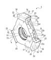
- FIG. 1 is a perspective view of a cutting insert according to the first embodiment of the present invention.
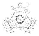
- FIG. 2 is a top view of the cutting insert of FIG.
- FIG. 3 is a bottom view of the cutting insert of FIG.
- FIG. 4 is a left side view of the cutting insert of FIG.
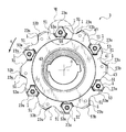
- FIG. 5 is an end view of a cutting tool equipped with the cutting insert of FIG. 1 according to the first embodiment of the present invention.
- FIG. 6 is a front view of the cutting tool of FIG.
- FIG. 7 is a view relating to the cutting insert and the insert mounting seat in a portion surrounded by a circle VII in FIG. 5, and is a view in a state where the mounting screw is removed.
- 8 is a cross-sectional view taken along line VIII-VIII in FIG. FIG.
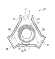
- FIG. 9 is a perspective view of a cutting insert according to the second embodiment of the present invention.
- FIG. 10 is a top view of the cutting insert of FIG.
- FIG. 11 is a bottom view of the cutting insert of FIG. 9.
- FIG. 12 is an end view of a cutting tool equipped with the cutting insert of FIG. 9 according to the second embodiment of the present invention.
- FIG. 13 is a front view of the cutting tool of FIG.
- FIG. 14 is a view showing a modification of the cutting insert according to the present invention.
- FIG. 15 is a view showing another modification of the cutting insert according to the present invention.
- FIG. 16 is a view showing still another modified example of the cutting insert according to the present invention.
- FIG. 17 is a view showing still another modified example of the cutting insert according to the present invention.
- FIG. 18 is a perspective view of a conventional cutting insert.
- FIG. 19 is a perspective view of another conventional cutting insert.
- the cutting insert 1 is shown in FIGS.
- the cutting insert 1 includes an upper surface 5 and a lower surface 7 that face each other or are opposite to each other, and a peripheral side surface 9 that extends between them.
- the upper surface 5 and the lower surface 7 are substantially parallel.
- the cutting insert 1 is defined with an axis A passing through the upper surface 5 and the lower surface 7 and is substantially rotationally symmetric around the axis A.
- An insert mounting hole 11 having a central axis that coincides with the axis A is formed so as to penetrate the upper surface 5 and the lower surface 7.
- the cutting insert 1 includes an insert body portion 13 and three projecting portions 15 provided integrally with the insert body portion 13.
- the insert body part 13 includes a body part upper surface 17, a body part lower surface 19, and a body part side surface 21 extending therebetween.
- the body part upper surface 17 and the body part lower surface 19 face each other or are positioned on the opposite side with respect to each other, and are substantially parallel to each other.
- One projecting portion 15 is disposed between any two side surfaces 21 of the three body portion side surfaces 21.
- excluding the protrusion part 15 from the cutting insert 1 can be defined as the insert body part 13.
- the insert body portion 13 is designed so as to substantially have a rotationally symmetric shape around the axis A, that is, the center axis of the insert mounting hole 11. Similarly, three protrusions 15 are arranged at rotationally symmetric positions around the axis A. Thus, as described above, the cutting insert 1 is formed so as to have a substantially rotationally symmetric shape around the axis A.
- the three projecting parts 15 are positioned so as to be positioned at the top of the triangle of the body upper surface 17 (FIG. 2). reference).
- the protruding portion 15 is provided around the insert body portion 13 at a position outside the insert body portion 13 in the direction orthogonal to the axis A. That is, the projecting portion 15 is provided so as to project or extend outward from the insert body portion 13.
- the three protrusions 15 have substantially the same configuration. Therefore, unless otherwise specified, any one protrusion 15 will be described below.
- the projecting portion 15 has a cutting edge 23 and is provided at an outer position of the insert body portion 13 in a direction orthogonal to the axis A.
- the protrusion 15 has a substantially rectangular parallelepiped shape.
- the protrusion 15 includes a protrusion upper surface 25 connected to the body upper surface 17, a protrusion lower surface 27 connected to the body lower surface 19, and two protrusion side surfaces 29 each connected to the corresponding body side surface 21. And the protrusion part side end surface 31 extended between these.
- a corner R surface (corner curved surface) 33 extending between the protrusion upper surface 25 and the protrusion-side end surface 31 is formed on the protrusion 15 from one of the two protrusion side surfaces 29 to the other. ing.
- the first plane can extend to include the axis A. 2 and 3 show the first plane S for one protrusion.
- the protruding portion 15 is provided so as to be substantially bisected by the first plane S, and is formed to be substantially plane-symmetric with respect to the first plane S.
- the corner R surface 33 is formed to have the same or substantially the same curvature on an arbitrary plane parallel to the first plane S. However, the corner R surface 33 may have a different curvature on an arbitrary plane parallel to the first plane.
- the length L between the two protrusion side surfaces 29 in one protrusion 15, that is, the length L of the corner R surface 33 of the protrusion 15 in the direction between the two protrusion side surfaces is determined within a predetermined range. Yes.
- an inscribed circle IC can be defined on the body upper surface 17 of the insert body part 13.
- the length L of the corner R surface 33 shown in FIG. 2, that is, the length of the corner R surface 33 in the direction orthogonal to the first surface is shorter than the diameter of the inscribed circle IC. Therefore, compared with the size of the insert body part 13, the length of the corner R surface 33 becomes sufficiently short. Further, the length L of the corner R surface 33 is preferably equal to or greater than the thickness T (see FIG.
- the upper surface 5 of the cutting insert 1 includes a body upper surface 17 of the insert body 13 and projecting portion upper surfaces 25 of the three projecting portions 15.
- the lower surface 7 of the cutting insert 1 includes a body portion lower surface 19 of the insert body portion 13 and projecting portion lower surfaces 27 of the three projecting portions 15.
- the peripheral side surface 9 of the cutting insert 1 includes a body side surface 21 of the insert body portion 13, a protruding portion side surface 29 of the three protruding portions 15, and a protruding portion side end surface 31.
- Two cutting edges 23 are formed on one protrusion 15.
- the two cutting edges 23 have substantially the same configuration except that they are symmetric with respect to the first surface. Therefore, those cutting edges 23 are described using the same reference numerals unless otherwise specified.
- the cutting edge 23 has a corner 23c formed along the edge of the corner R surface 33, and the protruding portion upper surface 25, the corner R surface 33, and the protruding portion side end surface 31 so that the protruding portion side surface 29 becomes a rake face.
- the curvature or radius of curvature of the corner 23c can be changed as appropriate according to the size of the corner curved surface of the groove desired to be formed in the work material.
- Two such cutting edges 23 are formed in one protrusion 15, and they are plane-symmetric with respect to the first surface S as is apparent from the drawings.
- one cutting edge in one protrusion 15 can be regarded as a right-handed cutting edge, and the other cutting edge can be regarded as a left-handed cutting edge. Therefore, in the cutting insert 1, three cutting edges can be used as a right-handed cutting edge, and another three cutting edges can be used as a left-handed cutting edge.
- the cutting insert 1 is an indexable cutting insert.
- the right-handed cutting edge is a cutting edge on the right side when the cutting insert 1 is viewed from the direction of the cutting edge.
- the left-handed cutting edge is the cutting edge 1 viewed from the direction of the cutting edge. Sometimes the cutting edge on the left side.
- each cutting edge 23 is formed so that the corresponding protrusion side surface 29 becomes a rake face as described above.
- the projecting portion upper surface 25, the projecting portion side end surface 31, and the corner R surface 33 serve as flank surfaces.
- the protruding portion side surface 29 is formed so as to be gradually inclined inward from the vicinity of the cutting edge, in particular, from the vicinity of the intersecting ridge line portion between the protruding portion side surface 29 and the protruding portion upper surface 25 to the protruding portion lower surface 27 side. Yes. Therefore, in one protrusion 15, the length between the protrusion side surfaces 29 becomes shorter from the protrusion upper surface 25 to the protrusion lower surface 27 side. Furthermore, as can be understood from FIG.
- the protrusion side surface 29, that is, the rake face is inclined so that the length between the protrusion side surfaces 29 decreases as the distance from the cutting edge 23 increases.
- the protruding portion side surface 29 is substantially formed of a flat surface, but may be formed of a curved surface, may be formed of a combination of a flat surface and a curved surface, and has irregularities. May be.
- Such a shape of the protrusion side surface 29 can contribute to setting the rake angle in the radial direction of the cutting edge of the cutting insert 1 in the cutting tool 3 to the positive side.
- the length between the protrusion side surfaces 29 is not substantially different depending on the location, that is, the protrusion side surface 29 is parallel to the axis A.
- the protrusion side surface 29 is allowed to be formed to extend.
- the lower surface 7 of the cutting insert 1 including the body lower surface 19 and the projecting portion lower surface 27 includes a substantially annular peripheral portion 7a formed as a flat plane and a concave portion 7b formed around the mounting hole 11.
- the shape of the insert mounting seat of the cutting tool and the recess 7b have a correspondence relationship.
- such a recess 7b may not be formed, and in this case, the insert mounting seat does not have a portion corresponding to the recess 7b.
- the lower surface 7 can be formed in a curved shape or can be formed with irregularities.
- the lower surface 7 functions as an insert seating surface as will be described later, the lower surface 7 can be formed in consideration that the cutting insert 1 can be indexed.
- a single body side surface 21 is formed between the two protrusions 15 each having such a configuration.
- the body side surface 21 includes an upper surface side surface portion 21a, a lower surface side surface portion 21b, and an intermediate side surface portion 21c positioned therebetween.
- the upper surface side surface portion 21a is further away from the axis A than the lower surface side surface portion 21b, and is configured to function as a seating surface.
- the intermediate side surface portion 21c is formed so as to protrude outward and forms a protruding portion R.
- the raised portion R is designed to increase the thickness of the insert body portion 13 in the direction orthogonal to the axis A, and thus contribute to the increase in strength of the cutting insert 1.
- the intermediate side surface portion 21c that is, the raised portion R is not intended to function as a seating surface. Therefore, when the cutting insert 1 is viewed from the flat surface of the cutting insert 1, that is, when the cutting insert 1 is viewed from the side facing the upper surface 5 or the body upper surface 17, the raised portion R is hidden by the body upper surface 17.
- the raised portion R is formed so as not to be visible. However, in the cutting insert 1, the raised portion R is formed so that the raised amount increases as the distance from each of the adjacent protruding portions 15 increases. However, the raised portion R can be raised in a manner other than such a manner.
- marks M1, M2, and M3 (see FIG. 3) formed on the intermediate side surface portion 21c of the cutting insert 1 are used especially for a used cutting edge and an unused one so that the position or orientation of the insert can be easily understood. It is provided in order to discriminate the cutting edge more reliably.
- markings can be different markings, can be omitted, or can be provided at other locations.
- the cutting insert 1 can be made of a hard material such as cemented carbide, coated cemented carbide, cermet, ceramic, or ultra-high pressure sintered body containing diamond or cubic boron nitride.
- the cutting insert 1 having such a configuration is detachably attached to the tool body 41 of the rotary cutting tool 3 as shown in FIGS.
- the cutting tool 3 is rotated around the rotation axis O.
- the tool body 41 is basically composed of two end surfaces 43, 45, an outer peripheral surface 47 extending between the two end surfaces 43, 45, and a bore hole 49 penetrating the center of the two end surfaces 43, 45. ing.
- the two end faces 43 and 45 are opposed to each other, i.e., opposite to each other, and each has a substantially circular shape.
- a chip pocket 51 and a plurality of insert mounting seats 53 are formed on the outer peripheral surface 47 of the tool body 41.
- the chip pocket 51 is provided so as to suitably discharge the chip.
- the insert mounting seat 53 has two types of insert mounting seats 53 a and 53 b, each of which is provided on the outer peripheral surface on the rear side in the tool rotation direction K adjacent to the corresponding chip pocket 51.
- One of the insert mounting seats 53a and 53b is an insert mounting seat for a right-handed cutting blade, and the other is an insert mounting seat for a left-handed cutting blade. To distinguish these, one of them may be referred to as the first insert mounting seat and the other as the second insert mounting seat.
- the first insert mounting seat 53a opens to one of the two end surfaces 43 and 45
- the second insert mounting seat 53b opens to the other of the two end surfaces 43 and 45. Therefore, as can be well understood from FIGS. 5 and 6, the first and second insert mounting seats 53 a and 53 b are alternately formed in a staggered pattern on each of the two end surfaces 43 and 45 of the tool body 41.
- the insert 1 is alternately mounted on each of the two end surfaces 43 and 45 in a staggered manner.
- the first insert mounting seat and the second insert mounting seat have a symmetrical shape with respect to each other, and are substantially the same in other respects. Therefore, in the following, detachable mounting of the cutting insert will be described with respect to any one insert mounting seat.
- the cutting insert 1 is vertically mounted on the insert mounting seat 53 (53a, 53b) so that the corner 23c of the usable cutting edge 23u protrudes outward.
- the protruding portion side end surface 31 of the protruding portion 15 of the cutting insert 1 substantially coincides with the outer peripheral surface 47 of the tool body 41, and the corner R surface 33 of the protruding portion 15 is positioned outside. ing.
- FIG. 7 is a view showing a state in which the mounting screw 55 is removed and the cutting insert 1 is simply disposed on the insert mounting seat 53, and the seating surface of the cutting insert 1 is brought into contact with the contact surface of the insert mounting seat 53. It is an enlarged view showing.
- FIG. 8 is a sectional view taken along line VIII-VIII in FIG.
- the insert mounting seat 53 includes a bottom wall surface 53c brought into contact with the lower surface 7 of the cutting insert 1, and side wall surfaces 53d and 53e substantially perpendicular to the bottom wall surface 53c.
- a protrusion 53f is formed on the bottom wall surface 53c, and a screw hole 57 into which a mounting screw 55 for attaching the cutting insert 1 is screwed is formed in the protrusion 53f.
- the protrusion 53 f is shaped so as to be received in the recess 7 b of the cutting insert 1 with a gap.
- the axis A of the mounting hole 11 of the cutting insert 1 and the axis B of the screw hole 57 of the insert mounting seat 53 are as follows.
- the holes 11, 57 are related so that they are offset. However, at this time, the axes A and B of these holes are parallel to each other. Therefore, when the mounting screw 55 is screwed into the screw hole 57 of the insert mounting seat 53 through the mounting hole 11 of the cutting insert 1, the cutting insert 1 is pressed against the side wall surfaces 53d and 53e of the insert mounting seat 53, particularly the side wall surface 53d. It is firmly fixed.
- the upper surface side surface part 21a of the body part side surface 21 of the cutting insert 1 is maintained firmly in contact with the side wall surfaces 53d and 53e.
- the cutting insert 1 is attached to the insert mounting seat 53 in this way, one usable cutting edge 23u of one protrusion 15 is exposed, but the other two protrusions 15 are particularly cut.
- the protrusion 15 positioned rearward in the rotation direction R of the tool 3 is received or accommodated in the corresponding recesses 53g and 53h of the insert mounting seat 53 in a non-contact state. Therefore, the cutting edges 23 other than the usable cutting edge 23u are not involved in cutting, and in particular, the cutting edge of the protrusion 15 that does not have the usable cutting edge 23u can be more appropriately protected. .
- the cutting insert 1 is provided with the protrusion part 15, and the cutting edge 23 is provided there. Therefore, the length between the protruding portion side surfaces 29 of one protruding portion 115, particularly the length L between the corners 23c of the two cutting edges 23, can be made smaller than the diameter of the inscribed circle IC of the insert body portion 13. .
- the rake angle in the radial direction of the cutting edge 23 can be set to the positive side more easily than the conventional cutting insert.
- the rake angle in the radial direction can be set to a desired angle without reducing the size of the cutting insert, so that the cutting resistance can be greatly reduced without reducing the strength of the cutting insert. Is possible.
- the corner R surface can be set with respect to the cutting edge for each protrusion, so the size of the corner of the cutting edge or the corner R surface can be freely set without reducing the number of cutting edges of the cutting insert. Can be set.
- the protrusion part 15 which protrudes from there is provided in the insert body part 13
- size of the protrusion part 15 in which the cutting edge is provided as mentioned above is very compared with the magnitude
- the back support part of a tool main body can be taken large. That is, as shown in FIG. 5, the volume of the tool body portion behind the cutting edge is increased as compared with the prior art. Therefore, according to the cutting insert and the cutting tool of this embodiment, the cutting insert is more It can be stably supported on the tool body, thereby reducing the occurrence of chatter.
- the lower surface 7 of the cutting insert and the body side surface 21 of the insert body portion 13 are used as seating surfaces, and the surfaces other than the lower surface 27 of the projecting portion 15 are used as cutting insert restraint surfaces or seating surfaces. do not do. Therefore, it is possible to protect the corner R surface of the protrusion 15 that is not used, and it is possible to assemble the cutting insert 1 stably even if the corner R surface is large.
- the corner R portion serving as the restraining surface and the tool body are excessively excessive.
- the corner R portion may be damaged by the contact, and when the corner R surface is large, the contact area with the tool main body becomes small, so that the cutting insert fixability may be deteriorated.
- the cutting insert 1 and the rotary cutting tool 3 have a structure in which the portion where the corner R surface is formed is housed in a recess or pocket provided in the tool body, and the side of the body portion is constrained by the cutting insert. Since it is used as a surface, the corner R surface can be protected and stable fixing of the cutting insert can be realized.
- a cutting insert 101 and a cutting tool 103 according to a second embodiment of the present invention will be described.
- the same or substantially the same components as those already described are denoted by the same reference numerals, in particular, the same reference numerals in the drawings, and redundant description thereof is omitted.
- the features or configurations described in the first embodiment are similarly applied to the cutting insert 101 and the cutting tool 103 of the second embodiment.
- the cutting insert and the cutting tool of the second embodiment can be modified in the same manner as those of the first embodiment, and the same operational effects can be achieved.
- the cutting insert 101 has an upper surface 5, a lower surface 7, and a peripheral side surface 9, as with the cutting insert 1, and includes an insert body portion 13 and three projecting portions 15.
- the cutting insert 101 is formed around the axis A so as to be rotationally symmetric.
- the cutting insert 101 is different from the cutting insert 1 in the body part side surface 121 of the insert body part 13.
- the body side surface 121 of the cutting insert 101 includes an upper surface side surface portion 121a, a lower surface side surface portion 121b, and an intermediate side surface portion 121c positioned therebetween.
- the intermediate side surface portion 121c has a rectangular surface portion 121d extending so as to project obliquely outward from the corresponding protruding portion 15, and a triangular shape extending between the upper surface side surface portion 121a and the two rectangular surface portions 121d.
- a surface portion 121e is positioned between the upper surface side surface portion 121a and the two rectangular surface portions 121d.
- the cutting insert 101 is viewed from the side facing the upper surface of the body portion.
- the raised portion R is formed so as to be hidden by the body portion upper surface 17 (see FIG. 10).
- the cutting insert 101 having such a configuration is detachably attached to the tool body 41 of the rotary cutting tool 103 as shown in FIGS.
- the tool body 41 is the same as the tool body 41 of the first embodiment, and has a first insert mounting seat and a second insert mounting seat.
- a cutting insert is attached to the tool body 41 as described in the first embodiment (see FIGS. 5 to 8, FIGS. 12 and 13).
- the cutting insert 101 and the cutting tool 103 of such 2nd Embodiment have the said characteristic similarly to the cutting insert 1 and the cutting tool 3 of the said 1st Embodiment, and there can show an above-described effect. .
- the cutting insert of this invention is not limited to what the flat surface view like the said embodiment has a substantially triangular shape.
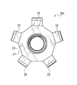
- the body upper surface 17 of the insert body 13 is regarded as a regular tetragon or a regular pentagon, and the protrusion 15 is provided so as to be located at the top thereof.
- the present invention allows cutting inserts 201 and 301.
- the cutting insert can be configured such that the upper surface of the insert body portion 13 is regarded as various regular polygonal shapes.
- it is also possible to form the upper surface of the insert body portion so that it is not a regular polygon but an unequal side polygon having different lengths. Even in such a polygonal cutting insert, a characteristic configuration related to the protruding portion as described above may be provided.
- the body upper surface 17 of the insert body 13 is regarded as a polygonal shape such as a triangle or a quadrangle, and the protrusions 15 are provided so as to be located on the sides thereof.
- the present invention allows for the cutting inserts 401, 501 made. Even in this case, the features described based on the above embodiment, such as the length of the corner R surface of the protrusion, can be applied.
- body part upper surface 17 of the insert body part 13 may be circular or elliptical.
- the plurality of protrusions in one cutting insert have the same or similar configuration.
- the plurality of protrusions in one cutting insert may be different from each other.
- the corner R surface continuously extends between the side surfaces of the protrusions, but may not be continuous between the side surfaces of the protrusions.
- one corner R surface 33 is continuous between the side surfaces 29 so as to form the corner 23 c at the cutting edge 23 at the edge of each of the two protruding portion side surfaces 29.
- the corner R surface or corner curved surface in one protrusion 15 may be composed of at least two separate corner R surfaces or corner curved surfaces separated by one or more breaks (eg, nicks). .
- one corner R surface of one protrusion is connected to one protrusion side surface 29 and one corner having one corner 23c at the edge. It is possible to include a total of two corner surface portions including a surface portion and one corner surface portion connected to the other protrusion side surface 29 and having one corner 23c at the edge.
- the first and second insert mounting seats are provided so as to open on both end faces of the tool body.
- a plurality of insert mounting seats having the same configuration may be formed only on one of the end faces. That is, the present invention also includes a so-called half-side cutting tool.
Landscapes
- Engineering & Computer Science (AREA)
- Mechanical Engineering (AREA)
- Milling Processes (AREA)
- Cutting Tools, Boring Holders, And Turrets (AREA)
Abstract
Description
Claims (9)
- インサート体部(13)であって、体部上面(17)と、該体部上面(17)の反対側にある体部下面(19)と、該体部上面(17)と該体部下面(19)との間に延在する体部側面(21)とを備え、該体部上面(17)および該体部下面(19)を通過する軸線(A)が定められる、インサート体部(13)と、
複数の突出部(15)であって、各々が切れ刃(23)を有して、各々が該軸線(A)に直交する方向における該インサート体部(13)の外側位置に該インサート体部(13)と一体的に設けられた、複数の突出部(15)と
を備え、
該突出部(15)は、該体部上面(17)につながる突出部上面(25)と、該体部下面(19)につながる突出部下面(27)と、各々が対応する体部側面(21)につながる2つの突出部側面(29)と、これらの間に延在する突出部側端面(31)とを有し、該突出部(15)には、該突出部上面と該突出部側端面との間に延在するコーナR面(33)が形成され、
前記切れ刃(23)は、前記コーナR面(33)の縁部に沿って形成されるコーナ(23c)を有すると共に前記突出部側面(29)がすくい面となるように、前記突出部上面、前記コーナR面および前記突出部側端面と前記突出部側面との交差稜線部に沿って形成され、
2つの前記突出部側面(29)間の長さが前記体部上面において定められる内接円の直径(IC)よりも短いように、前記突出部(15)は設計されている、
切削インサート(1、101)。 - 2つの前記突出部側面(29)間の長さは、前記インサート体部(13)の厚みよりも大きい、請求項1に記載の切削インサート(1、101)。
- 前記インサート体部(13)の体部側面(21)には、隆起部(R)が形成されている、請求項1又は2に記載の切削インサート(1、101)。
- 前記体部上面(17)に対向する側から切削インサートを見たとき、前記隆起部(R)が隠されるように、該隆起部(R)は形成されている、請求項3に記載の切削インサート(1、101)。
- 前記突出部(15)は、前記インサート体部の前記体部上面(17)を多角形の形状とみなしたとき、該多角形の頂部に位置するように、形成されている、請求項1から4のいずれかに記載の切削インサート。
- 前記突出部(15)は、前記インサート体部の前記体部上面(17)を多角形の形状とみなしたとき、該多角形の辺部に位置するように、形成されている、請求項1から4のいずれかに記載の切削インサート。
- 前記インサート体部(13)の前記体部上面(17)は、略三角形状をなしていることを特徴とする請求項5または6に記載の切削インサート。
- 互いに対して反対側に位置する略円形の2つの端面(43、45)と、該端面間に延在する外周面(47)と、前記端面間を貫通しているボア穴(49)とを備える工具本体(41)を備える回転切削工具(3、103)であって、
該工具本体に設けられて、請求項1から7のいずれかに記載の切削インサート(1、101)が取り付けられるように構成されたインサート取付座(53)を備える、回転切削工具。 - 前記2つの端面の一方に開く第1インサート取付座(53a)と、
前記2つの端面の他方に開く第2インサート取付座(53b)と
を備える、請求項8に記載の回転切削工具。
Priority Applications (5)
| Application Number | Priority Date | Filing Date | Title |
|---|---|---|---|
| BR112013032386A BR112013032386A2 (pt) | 2011-06-17 | 2012-06-15 | Inserto de corte, e, ferramenta de corte rotatória |
| CN201280029773.1A CN103608142B (zh) | 2011-06-17 | 2012-06-15 | 切削刀片以及旋转切削工具 |
| JP2013520611A JP5672380B2 (ja) | 2011-06-17 | 2012-06-15 | 切削インサート及び回転切削工具 |
| EP12800349.8A EP2722122B1 (en) | 2011-06-17 | 2012-06-15 | Cutting insert and rotary cutting tool |
| US13/739,766 US9457413B2 (en) | 2011-06-17 | 2013-01-11 | Cutting insert and rotary cutting tool |
Applications Claiming Priority (2)
| Application Number | Priority Date | Filing Date | Title |
|---|---|---|---|
| JP2011134911 | 2011-06-17 | ||
| JP2011-134911 | 2011-06-17 |
Related Child Applications (1)
| Application Number | Title | Priority Date | Filing Date |
|---|---|---|---|
| US13/739,766 Continuation-In-Part US9457413B2 (en) | 2011-06-17 | 2013-01-11 | Cutting insert and rotary cutting tool |
Publications (1)
| Publication Number | Publication Date |
|---|---|
| WO2012173255A1 true WO2012173255A1 (ja) | 2012-12-20 |
Family
ID=47357233
Family Applications (1)
| Application Number | Title | Priority Date | Filing Date |
|---|---|---|---|
| PCT/JP2012/065426 Ceased WO2012173255A1 (ja) | 2011-06-17 | 2012-06-15 | 切削インサート及び回転切削工具 |
Country Status (6)
| Country | Link |
|---|---|
| US (1) | US9457413B2 (ja) |
| EP (1) | EP2722122B1 (ja) |
| JP (1) | JP5672380B2 (ja) |
| CN (1) | CN103608142B (ja) |
| BR (1) | BR112013032386A2 (ja) |
| WO (1) | WO2012173255A1 (ja) |
Cited By (5)
| Publication number | Priority date | Publication date | Assignee | Title |
|---|---|---|---|---|
| CN103212725A (zh) * | 2013-04-08 | 2013-07-24 | 株洲钻石切削刀具股份有限公司 | 一种切削刀片及切削刀具 |
| WO2015030183A1 (ja) * | 2013-08-30 | 2015-03-05 | 株式会社タンガロイ | 切削インサート及び刃先交換式切削工具 |
| RU2584625C1 (ru) * | 2014-12-04 | 2016-05-20 | Общество с ограниченной ответственностью "Сборные конструкции инструмента, фрезы Москвитина" | Дисковая фреза для обработки узких пазов и пластина для нее (варианты) |
| WO2017170403A1 (ja) * | 2016-03-28 | 2017-10-05 | 京セラ株式会社 | 切削工具用インサート |
| JP2017177307A (ja) * | 2016-03-31 | 2017-10-05 | 日本特殊陶業株式会社 | 切削インサート及び切削工具 |
Families Citing this family (12)
| Publication number | Priority date | Publication date | Assignee | Title |
|---|---|---|---|---|
| KR101478695B1 (ko) * | 2010-07-29 | 2015-01-02 | 쿄세라 코포레이션 | 절삭 인서트와 절삭 공구, 및 그것들을 사용한 절삭 가공물의 제조 방법 |
| JP5589244B2 (ja) * | 2010-10-06 | 2014-09-17 | 大昭和精機株式会社 | インサート |
| US9527142B2 (en) * | 2013-02-19 | 2016-12-27 | Iscar, Ltd. | High speed milling tool and tangential ramping milling insert therefor |
| US9296054B2 (en) * | 2013-05-23 | 2016-03-29 | Kennametal Inc. | Indexable cutting insert with a triangular shape |
| US9381583B2 (en) | 2014-02-12 | 2016-07-05 | Kennametal Inc. | Prismatic and cylindrical cutting inserts |
| USD744557S1 (en) * | 2014-05-12 | 2015-12-01 | Sumitomo Electric Hardmetal Corp. | Cutting insert |
| US10183347B2 (en) * | 2015-09-08 | 2019-01-22 | Iscar, Ltd. | Rotary cutting tool having axial position adjustment arrangement |
| US10160040B2 (en) | 2015-11-18 | 2018-12-25 | Iscar, Ltd. | Cutting tool and triangular-shaped indexable cutting insert therefor |
| US10035199B2 (en) * | 2016-06-30 | 2018-07-31 | Iscar, Ltd. | Cutting tool and triangular-shaped indexable cutting insert therefor |
| US10632548B2 (en) * | 2017-11-20 | 2020-04-28 | Iscar, Ltd. | Triangular-shaped indexable cutting insert having recessed side surfaces and rotary cutting tool |
| CN111906361A (zh) * | 2019-05-07 | 2020-11-10 | 肯纳金属印度有限公司 | 切割嵌件和旋转切割工具 |
| US11534838B1 (en) * | 2021-06-08 | 2022-12-27 | Iscar, Ltd. | Indexable lay-down cutting insert having a central body portion and three circumferentially spaced cutting portions, and cutting tool |
Citations (6)
| Publication number | Priority date | Publication date | Assignee | Title |
|---|---|---|---|---|
| JPH03117503U (ja) * | 1990-03-16 | 1991-12-04 | ||
| JPH06218626A (ja) * | 1990-01-23 | 1994-08-09 | Roger W Little | ねじ切する装置およびねじ切するインサート装置 |
| JPH06262422A (ja) | 1993-03-11 | 1994-09-20 | Dijet Ind Co Ltd | 転削工具のスローアウエイチップ |
| EP0850715A1 (de) * | 1996-12-31 | 1998-07-01 | Gebr. Heller Maschinenfabrik GmbH | Wendeschneidwerkzeug |
| JP2005528230A (ja) * | 2002-06-04 | 2005-09-22 | イスカーリミテッド | タンジェンシャル切削インサート及びフライス |
| JP2008105115A (ja) * | 2006-10-24 | 2008-05-08 | Mitsubishi Materials Corp | 切削工具 |
Family Cites Families (46)
| Publication number | Priority date | Publication date | Assignee | Title |
|---|---|---|---|---|
| DE2315044A1 (de) * | 1973-03-26 | 1974-10-10 | Hans Heinlein | Wendeplatte fuer spanabhebende werkzeuge |
| US4169690A (en) * | 1977-07-26 | 1979-10-02 | Kennametal Inc. | Cutting insert |
| JPS5830091B2 (ja) * | 1978-02-09 | 1983-06-27 | 株式会社神戸製鋼所 | 仕上用スロ−アウェイエンドミル |
| US4832541A (en) * | 1987-05-20 | 1989-05-23 | Sumitomo Electric Industries, Ltd. | Grooving insert |
| US5032050A (en) * | 1987-09-04 | 1991-07-16 | Kennametal Inc. | On-edge cutting insert with chip control |
| US5308197A (en) * | 1990-01-23 | 1994-05-03 | Threading Systems, Inc. | Machining apparatus |
| US5004379A (en) * | 1990-01-23 | 1991-04-02 | Little Roger W | Threading insert |
| US5088861A (en) | 1990-01-23 | 1992-02-18 | Threading Systems, Inc. | Threadmilling tool |
| SE470093B (sv) * | 1992-04-02 | 1993-11-08 | Sandvik Ab | Skär för skiv- eller planfräsar, samt fräsverktyg för sådana skär |
| US5725334A (en) * | 1993-03-29 | 1998-03-10 | Widia Gmbh | Cutting insert |
| DE59508102D1 (de) * | 1994-09-13 | 2000-05-04 | Widia Gmbh | Schneideinsatz |
| IL111976A (en) * | 1994-12-14 | 1997-11-20 | Iscar Ltd | Parting or grooving insert |
| SE505538C2 (sv) * | 1995-01-19 | 1997-09-15 | Seco Tools Ab | Metod och skär för gängning |
| SE505157C2 (sv) * | 1995-10-31 | 1997-07-07 | Seco Tools Ab | Metod och skär för gängning |
| DE19709436C2 (de) * | 1997-03-07 | 1999-03-04 | Felix Leeb | Zirkularbohrfräser |
| IL120422A0 (en) * | 1997-03-11 | 1997-07-13 | Iscar Ltd | A cutting insert |
| DE19738456A1 (de) * | 1997-09-03 | 1999-03-11 | Kennametal Inc | Gewindeschneidplatte |
| DE29810969U1 (de) * | 1998-06-19 | 1998-10-08 | Sandvik Ab, Sandviken | Schneideinsatz, Schneidwerkzeug zur spanenden Bearbeitung, insbesondere von rotationssymmetrischen Werkstückflächen |
| AT410770B (de) * | 1999-05-03 | 2003-07-25 | Boehlerit Gmbh & Co Kg | Verfahren, werkzeug und einrichtung zur spanabhebenden bearbeitung |
| DE10006381A1 (de) * | 2000-02-12 | 2001-08-16 | Sandvik Ab | Schneideinsatz und zugehöriges Fräswerkzeug |
| IL152161A (en) * | 2002-02-19 | 2008-03-20 | Jacob Friedman | Metal cutting tool |
| DE10218630A1 (de) * | 2002-04-25 | 2003-11-06 | Sandvik Ab | Fräser mit Feineinstellung |
| US7052214B2 (en) * | 2002-07-02 | 2006-05-30 | Janness Daniel L | Cutting insert and tool holder |
| AT6618U1 (de) * | 2002-08-16 | 2004-01-26 | Plansee Tizit Ag | Schneidwerkzeug zum drehen und bohren ins volle |
| IL154649A (en) * | 2003-02-27 | 2007-10-31 | Uzi Gati | Cutting placement for diligent operations |
| IL155288A (en) * | 2003-04-08 | 2007-09-20 | Amir Satran | Tangential cutting insert and milling cutter |
| JP4383129B2 (ja) * | 2003-08-28 | 2009-12-16 | 京セラ株式会社 | スローアウェイ式切削工具 |
| DE102006028062B4 (de) * | 2006-06-12 | 2008-09-18 | Vargus Ltd. | Wendeschneidplatte |
| US20080226403A1 (en) * | 2006-06-20 | 2008-09-18 | Kennametal Inc. | Indexable cutting insert with positive axial rake angle and multiple cutting edges |
| WO2008053633A1 (en) * | 2006-10-31 | 2008-05-08 | Kyocera Corporation | Cutting insert |
| JP5151361B2 (ja) * | 2007-03-12 | 2013-02-27 | 三菱マテリアル株式会社 | ねじ切り切削用インサート |
| SE531850C2 (sv) * | 2007-12-13 | 2009-08-25 | Seco Tools Ab | Skär och verktyg för spånavskiljande bearbetning |
| SE531855C2 (sv) * | 2007-12-20 | 2009-08-25 | Seco Tools Ab | Indexerbart svarvskär och ett skärverktyg som innefattar ett sådan skär |
| US8454277B2 (en) * | 2008-12-18 | 2013-06-04 | Kennametal Inc. | Toolholder and toolholder assembly with elongated seating pads |
| US9004823B2 (en) | 2009-03-05 | 2015-04-14 | Seco Tools Ab | Family of rotating cutting tools |
| IL198407A (en) * | 2009-04-23 | 2014-01-30 | Iscar Ltd | Cutting tools and cutting tool |
| SE534512C2 (sv) * | 2009-06-24 | 2011-09-13 | Sandvik Intellectual Property | Verktyg för spånavskiljande bearbetning samt solitt indexerbart skär och solid grundkropp härför |
| WO2011047126A1 (en) * | 2009-10-15 | 2011-04-21 | Sandvik, Inc. | Multiteeth indexable insert with locating means and material removal tool with same |
| KR101154704B1 (ko) * | 2010-02-19 | 2012-06-08 | 대구텍 유한회사 | 홈에 의해 분할된 절삭날을 갖는 절삭 인서트 및 이를 구비한 밀링 커터 |
| KR101478695B1 (ko) * | 2010-07-29 | 2015-01-02 | 쿄세라 코포레이션 | 절삭 인서트와 절삭 공구, 및 그것들을 사용한 절삭 가공물의 제조 방법 |
| IL210966A (en) * | 2011-01-31 | 2015-06-30 | Iscar Ltd | Tangential and milling |
| US8573904B2 (en) * | 2011-06-14 | 2013-11-05 | Kennametal Inc. | Grooving insert |
| JP5707653B2 (ja) * | 2011-06-17 | 2015-04-30 | 住友電工ハードメタル株式会社 | インサート及びインサートを備えたカッタ |
| US8734064B2 (en) * | 2011-08-24 | 2014-05-27 | Century Tool & Design, Inc. | Cutting insert for a machine tool |
| US8939684B2 (en) * | 2012-05-15 | 2015-01-27 | Iscar, Ltd. | Cutting insert with chip-control arrangement having recess depths and projection heights which increase with distance from cutting edge |
| US8714886B2 (en) * | 2012-06-19 | 2014-05-06 | Iscar, Ltd. | Threading cutting tool and double-sided indexable threading cutting insert therefor |
-
2012
- 2012-06-15 JP JP2013520611A patent/JP5672380B2/ja active Active
- 2012-06-15 WO PCT/JP2012/065426 patent/WO2012173255A1/ja not_active Ceased
- 2012-06-15 EP EP12800349.8A patent/EP2722122B1/en active Active
- 2012-06-15 BR BR112013032386A patent/BR112013032386A2/pt not_active IP Right Cessation
- 2012-06-15 CN CN201280029773.1A patent/CN103608142B/zh active Active
-
2013
- 2013-01-11 US US13/739,766 patent/US9457413B2/en active Active
Patent Citations (6)
| Publication number | Priority date | Publication date | Assignee | Title |
|---|---|---|---|---|
| JPH06218626A (ja) * | 1990-01-23 | 1994-08-09 | Roger W Little | ねじ切する装置およびねじ切するインサート装置 |
| JPH03117503U (ja) * | 1990-03-16 | 1991-12-04 | ||
| JPH06262422A (ja) | 1993-03-11 | 1994-09-20 | Dijet Ind Co Ltd | 転削工具のスローアウエイチップ |
| EP0850715A1 (de) * | 1996-12-31 | 1998-07-01 | Gebr. Heller Maschinenfabrik GmbH | Wendeschneidwerkzeug |
| JP2005528230A (ja) * | 2002-06-04 | 2005-09-22 | イスカーリミテッド | タンジェンシャル切削インサート及びフライス |
| JP2008105115A (ja) * | 2006-10-24 | 2008-05-08 | Mitsubishi Materials Corp | 切削工具 |
Non-Patent Citations (1)
| Title |
|---|
| See also references of EP2722122A4 |
Cited By (8)
| Publication number | Priority date | Publication date | Assignee | Title |
|---|---|---|---|---|
| CN103212725A (zh) * | 2013-04-08 | 2013-07-24 | 株洲钻石切削刀具股份有限公司 | 一种切削刀片及切削刀具 |
| CN103212725B (zh) * | 2013-04-08 | 2015-12-02 | 株洲钻石切削刀具股份有限公司 | 一种切削刀片及切削刀具 |
| WO2015030183A1 (ja) * | 2013-08-30 | 2015-03-05 | 株式会社タンガロイ | 切削インサート及び刃先交換式切削工具 |
| RU2584625C1 (ru) * | 2014-12-04 | 2016-05-20 | Общество с ограниченной ответственностью "Сборные конструкции инструмента, фрезы Москвитина" | Дисковая фреза для обработки узких пазов и пластина для нее (варианты) |
| WO2017170403A1 (ja) * | 2016-03-28 | 2017-10-05 | 京セラ株式会社 | 切削工具用インサート |
| JPWO2017170403A1 (ja) * | 2016-03-28 | 2018-10-11 | 京セラ株式会社 | 切削工具用インサート |
| CN108698143A (zh) * | 2016-03-28 | 2018-10-23 | 京瓷株式会社 | 切削工具用刀具 |
| JP2017177307A (ja) * | 2016-03-31 | 2017-10-05 | 日本特殊陶業株式会社 | 切削インサート及び切削工具 |
Also Published As
| Publication number | Publication date |
|---|---|
| US20130129433A1 (en) | 2013-05-23 |
| BR112013032386A2 (pt) | 2017-01-03 |
| EP2722122A4 (en) | 2015-06-24 |
| JPWO2012173255A1 (ja) | 2015-02-23 |
| CN103608142B (zh) | 2016-08-24 |
| CN103608142A (zh) | 2014-02-26 |
| EP2722122B1 (en) | 2020-10-14 |
| JP5672380B2 (ja) | 2015-02-18 |
| US9457413B2 (en) | 2016-10-04 |
| EP2722122A1 (en) | 2014-04-23 |
Similar Documents
| Publication | Publication Date | Title |
|---|---|---|
| JP5672380B2 (ja) | 切削インサート及び回転切削工具 | |
| CN107073604B (zh) | 切削刀片及刀头更换式旋转切削工具 | |
| CN113199071B (zh) | 切削刀片及刀尖更换式旋转切削刀具 | |
| JP6334515B2 (ja) | ショルダーミーリングカッター用の刃先割出し可能インサート及び刃先割出し可能インサートのための取付け切欠きを有するショルダーミーリングカッター | |
| JP5654212B2 (ja) | フライス加工用インサート | |
| EP3403751B1 (en) | Cutting insert and blade-tip-replaceable cutting tool | |
| CN109382530B (zh) | 切削刀片以及切削工具 | |
| JP6241636B2 (ja) | 切削インサートおよび刃先交換式切削工具 | |
| JP2005518949A (ja) | 金属切削用工具 | |
| CN104661779A (zh) | 切削刀片以及刀头更换式旋转切削工具 | |
| CN106687239A (zh) | 双面切削刀片和铣削工具 | |
| CN107000082A (zh) | 切削刀片以及刀尖更换式旋转切削刀具 | |
| JP5963034B2 (ja) | 切削インサート、工具ボデー及び刃先交換式回転切削工具 | |
| JP5988010B2 (ja) | 切削インサート、工具ボデーおよび切削工具 | |
| CN100402211C (zh) | 其边缘安装有镶块的刀具 | |
| JP2015196203A (ja) | 刃先交換式メタルソー | |
| JP6292425B2 (ja) | 刃先交換式回転切削工具 | |
| WO2015030183A1 (ja) | 切削インサート及び刃先交換式切削工具 | |
| JP5664409B2 (ja) | 刃先交換式ラフィングエンドミル | |
| JP6318558B2 (ja) | 切削インサートおよび刃先交換式穴加工工具 | |
| JP2015229235A (ja) | 刃先交換式切削工具ホルダ | |
| JP2014046435A (ja) | 切削インサート及びそれを用いた切削工具 | |
| JP2020517481A (ja) | ワークピースを機械加工するための切削インサートおよび工具 | |
| WO2015012232A1 (ja) | 切削インサートおよび切削工具 |
Legal Events
| Date | Code | Title | Description |
|---|---|---|---|
| 121 | Ep: the epo has been informed by wipo that ep was designated in this application |
Ref document number: 12800349 Country of ref document: EP Kind code of ref document: A1 |
|
| ENP | Entry into the national phase |
Ref document number: 2013520611 Country of ref document: JP Kind code of ref document: A |
|
| NENP | Non-entry into the national phase |
Ref country code: DE |
|
| ENP | Entry into the national phase |
Ref document number: 2013155900 Country of ref document: RU Kind code of ref document: A |
|
| REG | Reference to national code |
Ref country code: BR Ref legal event code: B01A Ref document number: 112013032386 Country of ref document: BR |
|
| ENP | Entry into the national phase |
Ref document number: 112013032386 Country of ref document: BR Kind code of ref document: A2 Effective date: 20131216 |