WO2012176748A1 - Dispositif d'entrée utilisant la détection de capacitance et de pression, et panneau tactile hybride de type capacitance équipé d'une fonction sensible à la pression - Google Patents
Dispositif d'entrée utilisant la détection de capacitance et de pression, et panneau tactile hybride de type capacitance équipé d'une fonction sensible à la pression Download PDFInfo
- Publication number
- WO2012176748A1 WO2012176748A1 PCT/JP2012/065565 JP2012065565W WO2012176748A1 WO 2012176748 A1 WO2012176748 A1 WO 2012176748A1 JP 2012065565 W JP2012065565 W JP 2012065565W WO 2012176748 A1 WO2012176748 A1 WO 2012176748A1
- Authority
- WO
- WIPO (PCT)
- Prior art keywords
- charge
- electrode
- pressure
- unit
- capacitance
- Prior art date
- Legal status (The legal status is an assumption and is not a legal conclusion. Google has not performed a legal analysis and makes no representation as to the accuracy of the status listed.)
- Ceased
Links
Images


Classifications
-
- G—PHYSICS
- G06—COMPUTING OR CALCULATING; COUNTING
- G06F—ELECTRIC DIGITAL DATA PROCESSING
- G06F3/00—Input arrangements for transferring data to be processed into a form capable of being handled by the computer; Output arrangements for transferring data from processing unit to output unit, e.g. interface arrangements
- G06F3/01—Input arrangements or combined input and output arrangements for interaction between user and computer
- G06F3/03—Arrangements for converting the position or the displacement of a member into a coded form
- G06F3/041—Digitisers, e.g. for touch screens or touch pads, characterised by the transducing means
- G06F3/044—Digitisers, e.g. for touch screens or touch pads, characterised by the transducing means by capacitive means
-
- G—PHYSICS
- G06—COMPUTING OR CALCULATING; COUNTING
- G06F—ELECTRIC DIGITAL DATA PROCESSING
- G06F3/00—Input arrangements for transferring data to be processed into a form capable of being handled by the computer; Output arrangements for transferring data from processing unit to output unit, e.g. interface arrangements
- G06F3/01—Input arrangements or combined input and output arrangements for interaction between user and computer
- G06F3/03—Arrangements for converting the position or the displacement of a member into a coded form
- G06F3/041—Digitisers, e.g. for touch screens or touch pads, characterised by the transducing means
- G06F3/0414—Digitisers, e.g. for touch screens or touch pads, characterised by the transducing means using force sensing means to determine a position
- G06F3/04144—Digitisers, e.g. for touch screens or touch pads, characterised by the transducing means using force sensing means to determine a position using an array of force sensing means
-
- G—PHYSICS
- G06—COMPUTING OR CALCULATING; COUNTING
- G06F—ELECTRIC DIGITAL DATA PROCESSING
- G06F3/00—Input arrangements for transferring data to be processed into a form capable of being handled by the computer; Output arrangements for transferring data from processing unit to output unit, e.g. interface arrangements
- G06F3/01—Input arrangements or combined input and output arrangements for interaction between user and computer
- G06F3/03—Arrangements for converting the position or the displacement of a member into a coded form
- G06F3/041—Digitisers, e.g. for touch screens or touch pads, characterised by the transducing means
- G06F3/0416—Control or interface arrangements specially adapted for digitisers
- G06F3/04166—Details of scanning methods, e.g. sampling time, grouping of sub areas or time sharing with display driving
-
- G—PHYSICS
- G06—COMPUTING OR CALCULATING; COUNTING
- G06F—ELECTRIC DIGITAL DATA PROCESSING
- G06F3/00—Input arrangements for transferring data to be processed into a form capable of being handled by the computer; Output arrangements for transferring data from processing unit to output unit, e.g. interface arrangements
- G06F3/01—Input arrangements or combined input and output arrangements for interaction between user and computer
- G06F3/03—Arrangements for converting the position or the displacement of a member into a coded form
- G06F3/041—Digitisers, e.g. for touch screens or touch pads, characterised by the transducing means
- G06F3/045—Digitisers, e.g. for touch screens or touch pads, characterised by the transducing means using resistive elements, e.g. a single continuous surface or two parallel surfaces put in contact
-
- G—PHYSICS
- G06—COMPUTING OR CALCULATING; COUNTING
- G06F—ELECTRIC DIGITAL DATA PROCESSING
- G06F2203/00—Indexing scheme relating to G06F3/00 - G06F3/048
- G06F2203/041—Indexing scheme relating to G06F3/041 - G06F3/045
- G06F2203/04106—Multi-sensing digitiser, i.e. digitiser using at least two different sensing technologies simultaneously or alternatively, e.g. for detecting pen and finger, for saving power or for improving position detection
Definitions
- the present invention relates to an input device for operating a specific area displayed on a screen using an input means such as a finger, and more particularly to an input device using both capacitance and pressure detection and an electrostatic device with a pressure-sensitive function.
- the present invention relates to a capacitive hybrid touch panel.
- a touch panel has been developed as an input device for inputting various information to an electronic device by operating a specific area displayed on the screen by means of input means such as a conductor such as a finger or a non-conductor such as a stylus. And is being offered to the market.
- various methods such as a resistance film method and a capacitance method are in practical use.
- a voltage is applied to one resistance film of an opposing resistance film (electrode), and a change in voltage corresponding to the operated position is detected in the other resistance film, thereby the position operated by the input means.
- electrode an opposing resistance film
- Capacitance method detects the position operated by the input means by detecting the change in capacitance between the input means and the conductive film or the change in capacitance between the conductive films (electrodes).
- a configuration using the capacitive method as a proximity sensor for a resistive film type input device has also been proposed. (For example, refer to Patent Document 3).
- a pressure detection element is used to detect the pressing force on the screen of the input means, and the detection result (pressure information) of the pressure detection element is used as one piece of information.
- a special region for providing the pressure detection element is required, and a special circuit configuration needs to be constructed.
- An object of the present invention is to provide an input device capable of detecting capacitance, resistance, and pressure with a simple circuit configuration and inputting various information including position information to an electronic device.
- An object of the present invention is to realize a highly versatile input device capable of inputting various information with high accuracy and quickly by operating the means.
- An input device is disposed so as to face each other so as to be electrically connectable, one of which is disposed between an electrode portion having an electrode to be operated and the facing electrode portion,
- a charging / discharging circuit having at least a constant current source, a switching element, a capacitor, and a resistance
- an input unit comprising: a pressure-sensitive layer whose electrical resistance changes according to pressure on the electrode unit to be operated by the body input means;
- a charge / discharge waveform forming unit that forms a charge / discharge waveform by connecting the input unit, based on the charge / discharge waveform formed by the charge / discharge waveform forming unit, and changes in capacitance and pressure in the input unit.
- a charge / discharge waveform calculation unit that detects and calculates the operation state, operation position, and operation pressure of the input unit, and the operation state, operation position, and operation pressure of the input unit calculated by the charge / discharge waveform calculation unit And an output unit, which outputs a signal indicating.
- the input device configured as described above detects changes in capacitance and pressure with a simple circuit configuration, and transmits information on the operation state, operation position, and operation pressure to the electronic device. Can be entered.
- the input unit according to the first aspect includes a capacitance detection signal indicating a capacitance between the input means and the operation target electrode.
- a resistance value detection signal indicating a resistance value between the electrode portions electrically connected via the pressure-sensitive layer is output to the charge / discharge waveform forming portion.
- the input device according to the second aspect of the present invention configured as described above forms a charge / discharge waveform by the detected capacitance detection signal and the resistance value detection signal, and the capacitance and pressure are applied to the charge / discharge waveform. It is configured so that the change of appears.
- the charge / discharge waveform forming unit according to the second aspect is connected to the input unit at least during discharging of the charge / discharge circuit, and the capacitance detection signal The charging / discharging waveform corresponding to the resistance value detection signal is formed.
- the input device of the third aspect of the present invention configured as described above is configured such that changes in capacitance and pressure appear in the waveform during discharge in the charge / discharge waveform, and the operation state, operation position, and operation It becomes possible to detect pressure.
- the charge / discharge waveform calculation unit calculates a discharge time between predetermined voltages in the charge / discharge waveform formed by the charge / discharge waveform forming unit. It is configured to calculate and detect a change in capacitance and pressure in the input unit, and form a signal indicating an operation state, an operation position, and an operation pressure of the input unit in the electrode unit to be operated.
- the input device configured as described above detects the change in capacitance and pressure based on the waveform at the time of discharge in the charge / discharge waveform, and determines the operation state, operation position, and operation. The pressure can be detected with high accuracy.
- the charge / discharge waveform forming unit according to the second aspect is connected to the input unit at least when the charge / discharge circuit is charged, and the capacitance detection signal The charging / discharging waveform corresponding to the resistance value detection signal is formed.
- the input device according to the fifth aspect of the present invention configured as described above is configured such that changes in capacitance and pressure appear in the waveform during charging in the charge / discharge waveform, and the operation state, operation position, and operation It becomes possible to detect pressure.
- the charging / discharging waveform calculation unit calculates a charging time between predetermined voltages in the charging / discharging waveform formed by the charging / discharging waveform forming unit. It is configured to calculate and detect a change in capacitance and pressure in the input unit, and form a signal indicating an operation state, an operation position, and an operation pressure of the input unit in the electrode unit to be operated.
- the input device configured as described above detects the change in capacitance and pressure based on the waveform during charging in the charge / discharge waveform, and determines the operation state, operation position, and operation. The pressure can be detected with high accuracy.
- the charge / discharge waveform forming section according to the second aspect is connected to the input section during charge / discharge of the charge / discharge circuit, and a capacitance detection signal The charging / discharging waveform corresponding to the resistance value detection signal is formed.
- the input device according to the seventh aspect of the present invention configured as described above is configured so that changes in capacitance and pressure appear in the waveform at the time of charging / discharging in the charging / discharging waveform, and the operation state, the operation position, and It becomes possible to detect the operating pressure.
- the charging / discharging time between predetermined voltages in the charge / discharge waveform formed by the charge / discharge waveform forming unit is the charge / discharge waveform calculating unit according to the seventh aspect. And a change in capacitance and pressure in the input unit is detected, and a signal indicating the operation state, operation position, and operation pressure of the input means in the electrode unit to be operated is formed. .
- the input device according to the eighth aspect of the present invention configured as described above detects the change in capacitance and pressure based on the waveform at the time of charging / discharging in the charging / discharging waveform, and the operation state, the operation position, and The operating pressure can be detected with high accuracy.
- the electrode part and the pressure-sensitive layer according to the first to eighth aspects are formed of a light-transmitting material, and are passed through the electrode part and the pressure-sensitive layer.
- the screen of the display device provided with the input device can be viewed and operated.
- the input device according to the ninth aspect of the present invention configured as described above can construct a device having excellent operability for the display device.
- a hybrid touch panel as an input device is a capacitive hybrid touch panel with a pressure-sensitive function, has a plurality of parallel first electrode lines, and is an operation target by a conductor input means.
- a first electrode part, and a second electrode part having a plurality of second electrode lines arranged orthogonally to the plurality of first electrode lines so as to be contactable / separable in a matrix and facing the first electrode part,
- the first electrode portion and the second electrode portion are disposed between the first electrode portion and the second electrode portion facing each other, and are pressed by the input means against the first electrode portion.
- a pressure-sensitive layer that is sandwiched and has an electric resistance that changes according to the pressure of the sandwich; the input unit is connected to the input unit; the first electrode unit; and the first electrode unit Between the first electrode part and the second electrode part And a resistance value detection signal indicating an electrical resistance value between the first electrode part and the second electrode part electrically connected via the pressure-sensitive layer from the input part.
- a detection circuit configured to detect an operation state, an operation position, and an operation pressure of the input means, and a plurality of switching elements that contact and separate each of the plurality of first electrode lines and the detection circuit.
- the thus configured hybrid touch panel can detect a change in capacitance and pressure (resistance value) with a simple circuit configuration, and can detect a capacitance detection signal from the input unit.
- the resistance value detection signal is input to the detection circuit, and the operation state, the operation position, and the operation pressure can be detected with high accuracy.
- the control unit includes a plurality of first elements collected for each predetermined number of adjacent first electrode lines.
- the electrode line group as the first detection electrode
- the switching element corresponding to the first detection electrode in the first drive unit is on / off controlled to drive and control the plurality of first electrode line groups.
- the two-electrode line is configured to be driven and controlled as the second detection electrode.
- the control unit according to the eleventh aspect performs the second selection on the second electrode line selected from the plurality of second electrode lines.
- the detection electrode the switching element corresponding to the second detection electrode in the second drive unit is on / off controlled to drive and control the selected second electrode line.
- the hybrid touch panel according to the twelfth aspect of the present invention configured as described above can detect a capacitance with high accuracy with a simple circuit configuration.
- the control unit according to the eleventh aspect includes a plurality of second elements collected for each predetermined number of adjacent second electrode lines.
- An electrode line group is used as a second detection electrode, and a switching element corresponding to the second detection electrode in the second drive unit is turned on / off to drive and control the plurality of second electrode line groups.
- the hybrid touch panel according to the thirteenth aspect of the present invention configured as described above can detect a capacitance with high accuracy with a simple circuit configuration.
- the detection circuit according to the tenth to thirteenth aspects includes at least a constant current source, a switching element, a capacitor, and a resistor.
- the electrostatic capacitance detection signal and the resistance value detection signal are input to form a charge / discharge waveform, and the charge / discharge waveform formed by the charge / discharge waveform formation unit.
- a charge / discharge waveform calculation unit that detects changes in capacitance and pressure in the capacitance detection signal and the resistance value detection signal and calculates an operation state, an operation position, and an operation pressure of the input means;
- the hybrid touch panel according to the fourteenth aspect of the present invention configured as described above forms a charge / discharge waveform based on the capacitance detection signal and the resistance value detection signal from the input unit, and changes in capacitance and pressure.
- the operation state, the operation position, and the operation pressure can be detected with high accuracy.
- the charge / discharge waveform forming unit according to the fourteenth aspect is connected to the input unit at least during discharging of the charge / discharge circuit, The charging / discharging waveform corresponding to the capacitance detection signal and the resistance value detection signal is formed.
- the hybrid touch panel according to the fifteenth aspect of the present invention configured as described above is configured so that changes in capacitance and pressure appear in the waveform during discharge in the charge / discharge waveform, and the operation state, operation position, and It becomes possible to detect the operating pressure.
- the charge / discharge waveform calculation unit is between predetermined voltages in the charge / discharge waveform formed by the charge / discharge waveform forming unit.
- the discharge time is calculated to detect changes in capacitance and pressure in the input unit, and a signal indicating the operation state, operation position and operation pressure of the input means in the electrode unit to be operated is formed.
- the hybrid touch panel according to the sixteenth aspect of the present invention configured as described above detects a change in capacitance and pressure based on a waveform during discharge in a charge / discharge waveform, and detects an operation state, an operation position, and The operating pressure can be detected with high accuracy.
- the charge / discharge waveform forming unit according to the fourteenth aspect is connected to the input unit at least during charging of the charge / discharge circuit, The charging / discharging waveform corresponding to the capacitance detection signal and the resistance value detection signal is formed.
- the hybrid touch panel according to the seventeenth aspect of the present invention configured as described above is configured such that changes in capacitance and pressure appear in the waveform during charging in the charge / discharge waveform, and the operation state, operation position, and It becomes possible to detect the operating pressure.
- the charge / discharge waveform calculation unit is between predetermined voltages in the charge / discharge waveform formed by the charge / discharge waveform forming unit.
- the charging time is calculated, a change in capacitance and pressure in the input unit is detected, and a signal indicating the operating state, operating position and operating pressure of the input means in the electrode unit to be operated is formed.
- the hybrid touch panel according to the eighteenth aspect of the present invention configured as described above detects a change in capacitance and pressure based on a waveform during charging in a charge / discharge waveform, and detects an operation state, an operation position, and The operating pressure can be detected with high accuracy.
- the charge / discharge waveform forming unit according to the fourteenth aspect is connected to the input unit during charge / discharge of the charge / discharge circuit,
- the charging / discharging waveform corresponding to the capacitance detection signal and the resistance value detection signal is formed.
- the hybrid touch panel of the nineteenth aspect according to the present invention configured as described above is configured such that changes in capacitance and pressure appear in the waveform at the time of charge / discharge in the charge / discharge waveform, and the operation state, the operation position, In addition, the operation pressure can be detected.
- the charge / discharge waveform calculation unit is between predetermined voltages in the charge / discharge waveform formed by the charge / discharge waveform forming part.
- the charge / discharge time is calculated to detect changes in capacitance and pressure in the input unit, and a signal indicating the operation state, operation position, and operation pressure of the input means in the electrode unit to be operated is formed. It is configured.
- the hybrid touch panel according to the twentieth aspect of the present invention configured as described above detects a change in capacitance and pressure based on the waveform at the time of charging / discharging in the charging / discharging waveform, and the operation state, the operation position, In addition, the operation pressure can be detected with high accuracy.
- the electrode part and the pressure-sensitive layer according to the tenth to twentieth aspects are formed of a light transmissive material, and the electrode part and the Through the pressure-sensitive layer, the screen of the display device provided with the hybrid touch panel can be visually observed and operated.
- the hybrid touch panel according to the twenty-first aspect of the present invention configured as described above can construct a device having excellent operability with respect to the display device.
- the input unit according to the tenth to twentieth aspects is provided on a film-like display device and operated via the display device. It is configured as follows.
- the hybrid touch panel according to the twenty-second aspect of the present invention configured as described above can accurately detect an operation state, an operation position, and an operation pressure as an input device of a film-like display device, for example, an organic EL (OLED). Will be able to.
- OLED organic EL
- the present invention it is possible to realize a highly versatile input device that can input various information with high accuracy and quickly by a simple operation of the input means. It is possible to reliably detect the pressure and input a large amount of information to the electronic device based on each detection result.
- the block diagram which shows the structure of the input device of Embodiment 1 which concerns on this invention.
- the flowchart which shows the detection sequence which detects an electrostatic capacitance and a pressure in the input device of Embodiment 1 which concerns on this invention.
- FIG. 1 is a diagram schematically showing a cross-sectional configuration of an input unit in the input device according to the first embodiment of the present invention.
- the input device of Embodiment 1 is a touch panel provided in a portable electronic device, and is provided on a liquid crystal screen of a display device.
- This input device will be described using an example in which the input device is entirely formed of a light transmissive material. Therefore, the input device according to the first embodiment can be operated visually with respect to a specific area displayed on the liquid crystal screen regardless of the type of input means, for example, whether the input means is a finger or a stylus. It is configured.
- a portable electronic device will be described as an example.
- the present invention is not limited to the portable electronic device, and various electronic devices having an input device used integrally with a display device. It is applicable to.
- the input unit 1 in the input device includes an upper electrode unit 10 and a lower electrode unit 20, which are a pair of electrode units arranged opposite to each other, and an upper electrode unit 10 and a lower electrode unit 20. And an adhesive portion 9 for fixing the upper electrode portion 10 and the lower electrode portion 20 so as to be able to contact and separate from each other. Therefore, when the upper electrode portion 10 is not pressed (pressed from the upper side to the lower side in FIG. 1), the upper electrode portion 10 has a predetermined distance (gap) with respect to the lower electrode portion 20. It arrange
- the upper electrode portion 10 when the upper electrode portion 10 is in a pressed load state in which the pressure is applied, the upper electrode portion 10 is electrically connected to the lower electrode portion 20 via the pressure sensitive layer 5. Therefore, the upper electrode portion 10 is configured to have flexibility so as to be able to contact and separate from the lower electrode portion 20.
- the upper electrode portion 10 that is one electrode portion is configured to include an upper film 2, an upper wiring pattern 3, and an upper detection electrode 4 that are input target surfaces, for example, fingers.
- the lower electrode portion 20 that is the other electrode portion includes a lower detection electrode 6, a lower wiring pattern 7, and a lower film 8 that is fixed to a substrate (not shown) of the display device.
- the pressure-sensitive layer 5 is formed on the surface of the lower detection electrode 6 facing the upper detection electrode 4 will be described.
- the upper detection electrode 4 It may be formed on the surface facing the lower detection electrode 6, and it has the same effect even if it is formed on any surface.
- the electrostatic formed between the finger and the upper electrode unit 10 by bringing the finger close to the upper film 2 serving as the operation target surface.
- a capacitance change occurs in capacitive coupling.
- the electrode portions are also capacitively coupled and have a capacitance.
- the upper detection electrode 4 and the lower detection electrode 6 are electrically connected through the pressure-sensitive layer 5 by bringing the finger closer and pressing the operation target surface of the upper film 2. At this time, the resistance value of the pressure-sensitive layer 5 changes according to the pressing force.
- the composition constituting the pressure-sensitive layer 5 is composed of a conductive material whose electric characteristics such as an electric resistance value change according to an external force.
- the composition of the pressure-sensitive layer 5 is directly applied between the conductive pressure-sensitive particles in the composition of the pressure-sensitive layer 5 by pressing the upper electrode portion 10 and the lower electrode portion 20 in contact with each other. Regardless of whether or not there is a general contact, a tunnel current flows and changes from an insulated state to an energized state. That is, the pressure-sensitive layer 5 has a characteristic that the electric resistance value changes according to the pressing force, and the electric resistance value decreases as the pressing force increases.
- the product names “QTC” and “QTC Clear” are obtained from Peratech Co., Ltd. of Darlington, England.
- a QTC ink which is a possible quantum tunnel phenomenon composite material (Quantum Tunneling Composite) can be used.
- the pressure-sensitive layer 5 of the input unit 1 in the first embodiment is formed on the surface of the lower detection electrode 6 facing the upper detection electrode 4 by coating.
- the pressure sensitive layer 5 can be formed using a printing method such as screen printing, offset printing, gravure printing, or flexographic printing.
- FIG. 2 is a block diagram illustrating a configuration of the input device according to the first embodiment.
- the input unit 1 shown in FIG. 1 has a capacitance detection 11 that detects a change in capacitance in the input unit 1 and a resistance value detection 12 that detects a change in electrical resistance value in the input unit 1. It is comprised so that it may serve as.
- the input device according to the first embodiment uses the capacitance detection signal (Cd) by the capacitance detection 11 and the resistance value detection signal (Rd) by the resistance value detection 12 to generate the charge / discharge waveform (Va).
- the capacitance change and resistance value change (pressure change) in the input unit 1 are detected, and the operation target surface
- a charge / discharge waveform calculation unit 14 for calculating a finger movement (operation state), a finger position (operation position) and a finger pressing force (operation pressure), and an operation state based on a signal from the charge / discharge waveform calculation unit 14;
- an output unit 15 that outputs a signal indicating an operation position and an operation pressure (see FIG. 2).
- FIG. 3 is a diagram illustrating a circuit configuration of the charge / discharge waveform forming unit 13.
- the circuit elements indicated by the variable capacitance (Cx) and the variable resistance (Rx) are the capacitance and resistance detected by the capacitance detection 11 and the resistance value detection 12 of the input unit 1 in the input device.
- the variable capacitance (Cx) includes input means such as a capacitance between the finger and the upper electrode portion 10, a capacitance between the upper electrode portion 10 and the lower electrode portion 20, and an input portion. 1 includes the capacitance of the circuit in FIG.
- the variable resistance (Rx) includes an electric resistance through the pressure-sensitive layer 5 between the upper electrode portion 10 and the lower electrode portion 20, an electric resistance included in a circuit in the input portion 1, and the like.
- the charge / discharge waveform forming unit 13 charges the capacitor C and the input unit 1 with the current from the constant current source 30 by the switching operation of the switching elements (SwA, SwB), and the resistor R and the input unit. 1 is configured to discharge.
- the constant current source 30 is connected to the capacitor C via the second switch B, and the first switch A is provided between the capacitor C and the resistor R.
- the capacitor C is connected to one input terminal of the comparator 31.
- a reference voltage (Vb) is input to the other input terminal of the comparator 31.
- the comparator 31 is configured to output a discharge end detection signal when the discharge voltage of the capacitor C reaches the reference voltage (Vb).
- the charge / discharge waveform forming unit 13 in the input device includes a charge / discharge circuit including a constant current source 30, a capacitor C, a resistor R, and two switching elements (SwA, SwB). .
- the input unit 1 is connected to the charge / discharge circuit, and a capacitance detection signal (Cd) formed by a variable capacitance (Cx) and a resistance formed by a variable resistor (Rx).
- a value detection signal (Rd) is input.
- the current from the constant current source 30 flows to the capacitor C and the input unit 1.
- the capacitor C and the input unit 1 are charged with a predetermined amount of charge (charging operation).
- a control method is used in which the charging operation is stopped when a predetermined amount of charge is charged in the capacitor C and the input unit 1 when the charging time reaches a certain time.
- Va charging voltage
- Vp predetermined voltage
- the discharging operation is started as the charging operation is stopped.
- the charge charged in the capacitor C and the input unit 1 flows through the resistor R and is discharged.
- the discharge state is affected by the variable capacitance (Cx) and the variable resistance (Rx) in the input unit 1.
- FIG. 4 is a waveform diagram of each element in the charge / discharge waveform forming unit 13.
- the charge / discharge waveform Va indicates the voltage waveform input from the capacitor C and the input unit 1 to the comparator 31, and SwA and SwB indicate the on / off states of the first switch A and the second switch B, respectively.
- Out in FIG. 4 indicates an output signal (discharge end detection signal) from the comparator 31.
- FIG. 4A is a waveform diagram in a state in which the input device is not operated (no operation state), and FIG. 4B is a diagram in which a finger as an input means approaches or closes the operation target surface of the input device. It is a wave form diagram of the state (proximity state) which contacted, (c) is an operation object surface of the input device pressed by a finger, and upper detection electrode 4 and lower detection electrode 6 are electrically passed through pressure-sensitive layer 5. It is a wave form diagram of the state (pressing load state) connected.
- the capacitor C and the input unit 1 intermittently repeat charging and discharging operations by turning on and off the first switch A and the second switch B. Therefore, the off period (Ta) of the first switch A is a predetermined period, and the on period Tb of the first switch A is almost equal when the capacitance change due to the capacitance detection 11 of the input unit 1 is small. In this period (Ta, Tb), in the non-operation state, ON / OFF is repeated in substantially the same period. Note that the first switch A performs a discharge operation that intermittently repeats the on / off operation in a very short time during the on period (Tb) (discharge operation period).
- the discharge waveform discharged at the resistor R through the first switch A is microscopically a stepped waveform.
- the on / off operation in the minute time in the first switch A is counted, and the discharge time is detected.
- the count of the on / off operation of the first switch A is detected by the charge / discharge waveform calculation unit 14 (see FIG. 2), and operation state information, operation position information, and operation pressure information can be formed by changing the count number. It becomes.
- the waveform diagram shown in FIG. 4B is a state in which a finger as input means is in proximity to or in contact with the operation target surface of the input device, and the upper detection electrode 4 and the lower detection electrode 6 are not in contact with each other. State. That is, the finger approaches the operation target surface, and the finger and the upper electrode unit 10 are in the capacitive coupling state. At this time, the upper electrode portion 10 and the lower electrode portion 20 are also in a capacitively coupled state. As a result, the variable capacitance (Cx) in the input unit 1 (see FIG. 3) in the state where the finger is close to or in contact with the operation target surface, compared to the no-operation state shown in FIG. ) Has changed.
- Cx variable capacitance
- the electrostatic capacitance between the finger and the upper electrode portion 10 increases as the finger approaches the operation target surface. Capacity increases.
- the detected discharge time Td in the charge / discharge waveform (Va) is longer by the time (Te) than the no-operation state shown in FIG.
- the detected discharge time (Td) is detected by the count number of the on / off operation of the first switch A for a very short time.
- the operation state information and the operation position information on the operation target surface of the finger can be determined by the change in the detected discharge time (Td) based on the change in the capacitance.
- the variable resistance (Rx) shown in FIG. 3 is infinite and is in a cut-off state.
- the operation target surface of the input device is pressed and pushed down by a finger, and the upper detection electrode 4 and the lower detection electrode 6 are electrically connected via the pressure-sensitive layer 5. It shows that it is in a pressed load state.
- the pressure-sensitive layer 5 has a characteristic that when pressed, the electric resistance value decreases according to the pressure.
- the pressed load state shown in FIG. 4C there is no capacitive coupling state as in the proximity state shown in FIG. 4B, and the finger as the input means and the upper electrode on the operation target surface The portion 10 and the upper electrode portion 10 and the lower electrode portion 20 are reliably electrically connected. Therefore, in the pressing load state shown in FIG.
- variable capacitance (Cx) shown in FIG. 3 is substantially zero, and a current flows through the variable resistor Rx.
- the variable capacitance Cx is not zero.
- the charge / discharge waveform (Va) in the period of the charge time (Ta), the charge period is insufficient, and it may not be possible to charge to the predetermined voltage (Vp). Due to the influence and the influence of the increase of the discharge current, the detected discharge time (Td) in the charge / discharge waveform (Va) is shortened by the time (Tn) as compared with the no-operation state shown in FIG.
- the detected discharge time (Td) is detected by the change in the electrical resistance in the input unit 1, the operation state information on the finger operation target surface, the operation position information on the finger operation target surface, and the finger operation target.
- the operation pressure information for the surface can be determined.
- the pressed load state includes a state where the upper electrode portion 10 and the lower electrode portion 20 are simply in electrical contact.
- FIG. 5 is a flowchart showing a detection sequence for detecting capacitance and pressure in the input device according to the first embodiment.
- step 1 (S1) in the detection sequence the charge / discharge waveform Va is formed by the charge / discharge waveform forming unit 13 as described above.
- the detected discharge time Td in the formed charge / discharge waveform is compared with the reference time (To).
- the reference time (To) is a discharge time Tb in the non-operating state (see FIG. 4A) in the input device, and is set using the time measured in the non-operating state.
- step 2 (S2) if the detected discharge time (Td) is substantially the same as the reference time (To), it is determined that there is no operation and the process returns to step 1 (S1).
- step 3 if the detected discharge time (Td) is longer than the reference time (To) by a certain period or longer, it is determined that the proximity state is present, and the process proceeds to the capacitance detection mode (S4). On the other hand, if the detected discharge time Td is shorter than the reference time To by a certain period or more, it is determined that the pressed load state is present, and the resistance value detection mode (S8) is entered.
- a capacitance detection process (S5) for detecting a change in capacitance (C + Cx: see FIG. 3) is performed based on the detected discharge time Td, and the detected electrostatic capacitance is detected.
- a capacitance detection output (S6) is performed based on the change in capacitance. That is, an operation state indicating whether or not the input device has been operated is detected.
- step 7 (S7) it is detected (release detection) whether or not the finger as the input means has been released from the input device.
- This release detection (S7) is performed in step 2 (S2), and is detected by comparing the detected discharge time (Td) with the reference time (To).
- step 3 If the detected discharge time (Td) is substantially the same as the reference time To, release detection is performed, and the detection sequence ends. Conversely, if the detected discharge time (Td) and the reference time (To) are different, the process returns to step 3 (S3) and shifts to the capacitance detection mode (S4) or the resistance value detection mode (S8).
- the resistance value detection mode (S8) based on the detected discharge time Td, a change in resistance value (R ⁇ Rx / R + Rx: see FIG. 3) is detected, and coordinate calculation processing and pressure calculation processing (S9) are performed. .
- this coordinate calculation processing one end of one of the opposing electrodes is connected to the input end of the detection circuit 50 constituted by the charge / discharge waveform forming unit 13 and the charge / discharge waveform calculating unit 14, and the other electrode
- the resistance value including the change of the pressure sensitive layer 5 can be measured by grounding one end of the pressure sensitive layer 5.
- the drive control unit 60 includes a plurality of switching elements, and performs switching control of each electrode in the coordinate calculation process and the pressure calculation process. Further, in the pressure calculation process, the resistance value changes according to the amount of pressure applied to the pressure sensitive layer 5, so the change in the resistance value at the specified coordinate position is detected to detect the pressing force (operation pressure). is doing.
- step 10 a signal indicating the detected coordinate position (operation position) and pressing force (operation pressure) is output to the control unit (not shown) of the portable electronic device provided with the input device. Shift to release detection.
- the detected discharge time (Td) is compared with the reference time (Vo) in the same manner as the release detection (S7) in the capacitance detection mode described above, and the detected discharge time (Td). Is the same as the reference time (Vo), release detection is performed, and the detection sequence ends. Conversely, if the detected discharge time (Td) and the reference time (Vo) are different, the process returns to step 3 (S3) and shifts to the capacitance detection mode (S4) or the resistance value detection mode (S8).
- the detection sequence in the input device according to the first embodiment is executed, and the capacitance (operation state), the coordinate position (operation position), and the pressing force (operation pressure) are detected, respectively.
- a signal is output to a control unit (not shown) of the portable electronic device provided with the input device, and the portable electronic device is controlled.
- the input means is not limited to a finger, and any conductor can be used.
- the capacitance detection signal (Cd) and the resistance value detection signal (Rd) can also be used for the charging waveform during charging.
- the capacitance detection signal (Cd) and resistance value detection signal (Rd) output from the input unit 1 at the time of charging it is detected that the behavior of the charging waveform changes according to the capacitance and resistance value.
- the present invention by using both the charging waveform during charging and the discharging waveform during discharging in the charging / discharging waveform (Va), a more accurate capacitance (operation state), coordinate position (operation position), and It is also possible to detect each pressing force (operation pressure). Also in this case, the capacitance detection signal (Cd) detected by the capacitance detection 11 in the input unit (1) described in the first embodiment and the resistance value detection signal (Cd) detected by the resistance value detection 12 ( By using Rd), changes appear in the charging waveform during charging and the discharging waveform during discharging depending on the capacitance (operation state), coordinate position (operation position), and pressing force (operation pressure). This phenomenon can be used, and detection with high accuracy becomes possible.
- the input unit 1 in the input device according to the first embodiment is provided on the liquid crystal screen of the display device and is formed of a light-transmitting material as a whole. Therefore, the input unit 1 is visually observed on the liquid crystal screen.
- one operation target surface is input by a finger as an input means. Therefore, the upper film 2, the upper wiring pattern 3, the upper detection electrode 4, the pressure sensitive layer 5, the lower detection electrode 6, the lower wiring pattern 7, and the lower film 8 in the input unit 1 are formed of a light transmissive material.
- air reffractive index: 1 exists in the configuration of the first embodiment.
- the liquid layer is, for example, a material having a refractive index close to that of each material in the components of the upper electrode portion 10 and the lower electrode portion 20, that is, having a refractive index higher than that of air, and has fluidity, light transmittance, and electrical insulation. It is preferable to use a material having heat resistance and heat resistance.
- the material of the upper film 2 and the lower film 8 is a general-purpose material such as polyethylene terephthalate, polystyrene resin, polyolefin resin, ABS resin, AS resin, acrylic resin, or AN resin that can be used for a flexible substrate. Resin can be used.
- the thicknesses of the upper detection electrode 4 and the lower detection electrode 6 are set to 5 ⁇ m to 25 ⁇ m, for example.
- materials for the upper detection electrode 4 and the lower detection electrode 6 it is preferable to use a transparent conductive material such as ITO, CNT, or Ag wire ink.
- a metal such as gold, silver, copper, or nickel, or a conductive paste such as carbon.
- the upper detection electrode 4 and the lower detection electrode 6 can also be formed by attaching a metal foil such as copper or gold. Further, the upper detection electrode 4 and the lower detection electrode 6 are formed by forming an electrode pattern with a resist on an FPC (flexible circuit board) plated with a metal such as copper, and etching a portion of the metal foil that is not protected by the resist. It can also be formed.
- FPC flexible circuit board
- the adhesive 9 is an insulating member that has adhesiveness to bond the upper film 2 and the lower film 8 and holds a gap between the opposing surfaces of the upper detection electrode 4 and the pressure-sensitive layer 5.
- the adhesive 9 is, for example, a double-sided pressure-sensitive adhesive tape in which a pressure-sensitive adhesive such as an acrylic adhesive paste is formed on both surfaces of a core material such as a polyethylene terephthalate film.
- the thickness of the adhesive 9 is set to 5 to 20 ⁇ m, for example.
- the adhesive 9 may be various adhesives such as UV curable resin and thermosetting resin and the thickness may be set to 5 to 20 ⁇ m.
- the input device provides the capacitance, resistance, and pressure with a simple circuit configuration regardless of the type of input means, for example, whether the input means is a finger or a stylus. It can detect and input operation state information, operation position information and operation pressure information to electronic equipment, and can be used to input various information with high accuracy and speed by operating simple input means. High input device.
- Embodiment 2 ⁇ Embodiment 2 >>
- the present invention is not limited to the specific configuration of the hybrid touch panel described in the second embodiment, and the same technology as the technical idea described in the second embodiment and the technology in this technical field. It includes a range configured based on common sense.
- the hybrid touch panel according to the present invention detects the operation state, the operation position, and the operation pressure by an operation by an input unit, for example, an operation by a finger, a stylus, etc. (including non-contact, contact and pressing operations).
- a configuration that can output various types of detected information.
- the hybrid touch panel as an input device has a configuration of a resistance type digital (multi) type touch panel and a configuration of a capacitance type self-type touch panel, and also presses the input means (finger).
- a capacitive hybrid touch panel with a pressure-sensitive function having a configuration capable of detecting pressure will be described as a second embodiment described later.
- the configuration of the capacitive hybrid touch panel with pressure-sensitive function described in Embodiment 2 is an example of an input device, and other configurations are also included in the present invention.
- a capacitive touch panel a plurality of electrode lines on the transmission side and a plurality of electrode lines on the reception side are arranged in a matrix (mesh shape), and between each transmission side electrode line and the reception side electrode line
- There is a mutual type touch panel that detects the capacitance of the input means and detects the operation state (operation state) and operation position (coordinate position) of the input means based on the detection result.
- a detection method in a mutual type touch panel is used in place of the detection method in a self type touch panel described in the second embodiment to construct a capacitive hybrid touch panel with a pressure sensitive function. It is also possible to do. That is, by utilizing the fact that the capacitance changes according to the operation state (operation state) and operation position (coordinate position) of the input means, and as a result, the behavior of the charge / discharge waveform described later changes, the operation state (Operating state) and operation position (coordinate position) can be detected.
- the configuration of a general resistive film type digital touch panel has an X-axis electrode line for detecting a position in the X-axis direction and a Y-axis electrode line for detecting a position in the Y-axis direction in a matrix shape (mesh Arranged).
- a general electrostatic capacity type self-type touch panel has an X-axis electrode line for detecting a position in the X-axis direction and a position for detecting a position in the Y-axis direction, like the configuration of a digital touch panel.
- Y-axis electrode lines are provided, each electrode line is configured to have a certain width in order to increase the capacitance detection sensitivity.
- the width of the electrode line is narrow and the detection sensitivity is lowered. There is a problem of doing.
- the detection target resistance value and electrostatic capacity
- the width of the receiving electrode line is widened and the width of the transmitting electrode line is narrowed to prevent a decrease in sensitivity due to mutual interference and improve detection sensitivity.
- the X-axis electrode line and the Y-axis electrode line are narrow and have the same width, and thus are different from the mutual touch panel. Therefore, even in the configuration of capacitance type mutual touch panel, when it is used for resistive film type digital touch panel, it is expected that the resolution and detection coordinate accuracy will decrease, so it cannot be easily combined. Met.
- the configuration of the resistive film type digital (multi) touch panel and the configuration of the capacitive type self (touch) type touch panel, or the configuration of the resistive film type digital (multi) touch panel A plurality of first electrode lines (Y-axis electrode lines, reception-side electrode lines) arranged in a matrix shape (mesh shape) are used in order to obtain a configuration that also has a capacitance type mutual touch panel configuration.
- a switching operation for grouping a plurality of electrode lines and / or a thinning-out switching operation is executed for each electrode line of the 10 and lower electrode portions 20 according to the situation.
- FIG. 6 is a diagram schematically showing a cross-sectional configuration of the input unit in the capacitive hybrid touch panel with pressure-sensitive function according to the second embodiment of the present invention.
- the hybrid touch panel of Embodiment 2 is a touch panel provided in a portable electronic device, and is provided on a liquid crystal screen of a display device.
- This hybrid touch panel will be described using an example in which the hybrid touch panel is formed entirely of a light transmissive material. Therefore, the hybrid touch panel of the second embodiment is configured to be operated by visually observing a specific area displayed on the liquid crystal screen with a finger.
- a portable electronic device will be described as an example.
- the present invention is not limited to the portable electronic device, and may be applied to various electronic devices having a touch panel used integrally with a display device. Applicable.
- the hybrid touch panel of the present invention may be arranged on the back surface of a film-like display device (organic EL (OLED)) or the like.
- the input unit 1 in the hybrid touch panel according to the second embodiment is an upper electrode unit that is a plurality of opposed electrode lines arranged (matrix-like (mesh-like)) arranged on an X-axis and Y-axis matrix. 10 and the lower electrode portion 20, the pressure sensitive layer 5 provided between the upper electrode portion 10 and the lower electrode portion 20, and an adhesive portion that holds (adheres) the upper electrode portion 10 and the lower electrode portion 20 so as to be able to contact and separate. 9 is provided. Therefore, when the upper electrode part 10 which becomes the operation target region (operation target surface) is not pressed (pressed from the upper side to the lower side in FIG. 6), the upper electrode part 10 is in contact with the lower electrode part 20.
- the upper electrode portion 10 is configured to have flexibility so as to be able to contact and separate from the lower electrode portion 20.
- the electrode lines in the upper electrode portion 10 and the lower electrode portion 20 are not limited to a linear shape, and may be a wave shape, a thickness that changes in the middle, or the like.
- the upper electrode part 10 which is one electrode part is provided on the back surface of the upper film 2 which becomes an operation target surface by a finger as an input means.
- the lower electrode part 20 which is the other electrode part is provided on the lower film 8 fixed to the substrate (not shown) of the display device.
- the pressure-sensitive layer 5 is formed on the lower electrode portion 20
- the heat-sensitive layer 5 may be formed on the upper electrode portion 10 on the opposite side. Even if formed, it has the same effect.
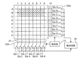
- FIG. 7 is an explanatory diagram showing the matrix configuration of the input unit 1 and the configuration of the switching elements in the hybrid touch panel of the second embodiment.
- the matrix-like upper electrode portion 10 and lower electrode portion 20 will be described using an example in which each is composed of eight electrode lines (A to H and 1 to 8) for easy explanation. .
- the first electrode lines (A to H) of the upper electrode part 10 are provided with switching elements (SwA to SwH), respectively, and each of the first electrode lines (A to H) is It is connected to a detection circuit 50 described later via switching elements (SwA to SwH).
- the second electrode lines (1 to 8) of the lower electrode portion 20 are provided with switching elements (Sw1 to Sw8), respectively, and the second electrode lines (1 to 8) are respectively connected to the switching elements (Sw1 to Sw1). It is connected to a detection circuit 50 described later via Sw8).
- the hybrid touch panel of the second embodiment in a state where a finger as an input means is close to or in contact with the operation target area of the hybrid touch panel, that is, in a state where the upper electrode portion 10 and the lower electrode portion 20 are not in contact with each other, The following switching control operation (capacitance detection process) is performed.
- a plurality of adjacent electrode lines are grouped together in the first electrode line (A to H).
- Switching control of each switching element (SwA to SwH) is executed so as to form one electrode line group.
- the switching control in which a plurality of adjacent electrode lines are collectively operated as one electrode group is performed by a plurality of switching elements (SwA to SwH) that turn on / off (contact / separate) each of the first electrode lines (A to H). This is executed by transmitting a drive control signal from the control unit 70 to the first drive circuit 60a having the above.
- the switching control that is controlled by the control unit 70
- three first electrode lines (A, B, C) are set as one first electrode line group X, and corresponding three switching elements (SwA, SwB, SwC) are turned on and connected to the detection circuit 50.
- the first electrode line group X is connected to the detection circuit 50, and the electrostatic capacitance in the first electrode line group X is detected.
- the second electrode lines (1 to 8) are set to a stable voltage (for example, a GND potential) in order to reduce the influence of capacitance on the first electrode line group X.
- the plurality of first electrode lines are combined to form the upper electrode group X, so that the substantial electrode width is widened and the detection sensitivity is increased.
- the detection sensitivity of the lower electrode can be increased by connecting the second electrode line to the detection circuit and setting the first electrode line to a stable voltage.
- the hybrid touch panel according to the second embodiment is configured to perform self-type capacitance detection
- the upper electrode unit 10 and the lower electrode 20 are used to detect the operation state of a finger as an input unit. It is possible to improve the detection sensitivity by optimizing the area by switching control of the switching element.
- the receiving electrode width of the receiving electrode portion that is the upper electrode portion is widened, and the transmitting electrode of the transmitting electrode portion that is the lower electrode portion By narrowing the width, detection sensitivity can be improved.
- the operation target surface of the hybrid touch panel is pressed and pushed down by a finger, and the corresponding electrode line in the upper electrode unit 10 is pressure-sensitive.
- the following switching control operations coordinate calculation processing and pressure calculation processing
- the detection circuit 50 of the hybrid touch panel When a pressing load state is detected in the detection circuit 50 of the hybrid touch panel, it is connected to the switching elements (SwA to SwH) connected to the first electrode lines (A to H) and the second electrode lines (1 to 8).
- the switching elements (Sw1 to Sw8) are sequentially turned on and off (resistance value detection process). Specifically, for example, in a state where one switching element (Sw1) for the lower electrode unit 20 is turned on and the second electrode line (1) is connected to the detection circuit 50, switching for the upper electrode unit 10 is performed. Switching control for once turning on the elements (SwA to SwH) sequentially is performed, and the first electrode lines (A to H) in the upper electrode portion 10 are sequentially connected to the detection circuit 50. Thus, by connecting the first electrode lines (A to H) to the detection circuit 50, the resistance values of all the first electrode lines (A to H) with respect to the second electrode line (1) are detected. Is detected.
- the switching control of all the switching elements (SwA to SwH) for the second electrode line (1) is completed, the switching control of the switching elements (SwA to SwH) for the next second electrode line (2) is completed. Similarly, it is carried out sequentially. As described above, the switching control of the switching elements (SwA to SwH) for all the second electrode lines (1 to 8) is sequentially performed, thereby detecting the resistance values at all the coordinate positions (detection points) in the operation target region. It will be detected in the circuit 50.
- the plurality of first electrode lines are grouped into one electrode line group, and the resistance value at each detection point is performed while performing the thinning operation on the second electrode lines. Detection processing may be executed. By performing the resistance value detection process in this manner, it is possible to increase the detection speed by reducing the detection points.
- the control unit 70 uses the plurality of second electrode lines grouped together for each predetermined number of adjacent second electrode lines (1 to 8) as the second detection electrodes.
- the switching element corresponding to the second detection electrode in the second drive unit 60b is on / off controlled to drive and control the plurality of second electrode line groups.
- the present invention is not limited to such a control method, and other control methods are possible.
- the control unit 70 uses the selected second electrode line (1, 3, 5, 7) thinned out from the plurality of second electrode lines (1 to 8) as the second detection electrode in the second drive unit 60b.
- the switching elements (Sw1, Sw3, Sw5, Sw7) corresponding to the second detection electrodes are on / off controlled to drive and control the selected second electrode lines (1, 3, 5, 7).
- the immediately preceding detection electrode is the first electrode line. (A, B)
- some of the electrode lines overlap such that the next detection electrode is the first electrode line (B, C) and the next detection electrode is the first electrode line (C, D).
- the electrostatic formed between the finger and the upper electrode unit 10 by bringing the finger closer to the upper film 2 serving as the operation target surface.
- a capacitance change occurs in capacitive coupling.
- the electrode portions are also capacitively coupled and have a capacitance.
- the upper electrode portion 10 and the lower electrode portion 20 are electrically connected via the pressure sensitive layer 5 by bringing the finger closer and pressing the operation target surface of the upper film 2. At this time, the resistance value of the pressure-sensitive layer 5 changes according to the pressing force.
- the composition constituting the pressure-sensitive layer 5 is composed of a conductive material whose electric characteristics such as an electric resistance value change according to an external force.
- the composition of the pressure-sensitive layer 5 is directly applied between the conductive pressure-sensitive particles in the composition of the pressure-sensitive layer 5 by pressing the upper electrode portion 10 and the lower electrode portion 20 in contact with each other. Regardless of whether or not there is a general contact, a tunnel current flows and changes from an insulated state to an energized state. That is, the pressure-sensitive layer 5 has a characteristic that the electric resistance value changes according to the pressing force, and the electric resistance value decreases as the pressing force increases.
- the product names “QTC” and “QTC Clear” are obtained from Peratech Co., Ltd. of Darlington, England.
- a QTC ink or the like that is a possible quantum tunneling composite material (Quantum Tunneling Composite) can be used.
- the pressure-sensitive layer 5 of the input unit 1 is formed on the surface of the lower electrode unit 20 facing the upper electrode unit 10 by coating.
- the pressure sensitive layer 5 can be formed using a printing method such as screen printing, offset printing, gravure printing, or flexographic printing.
- FIG. 8 is a block diagram showing the configuration of the hybrid touch panel according to the second embodiment.
- the input unit 1 illustrated in FIG. 6 includes the capacitance detection 11 that detects a change in capacitance in the input unit 1 and the resistance value detection 12 that detects a change in electrical resistance value in the input unit 1. It is comprised so that it may serve as.
- the hybrid touch panel of the second embodiment uses the capacitance detection signal (Cd) from the capacitance detection 11 and the resistance value detection signal (Rd) from the resistance value detection 12 to generate a charge / discharge waveform (Va).
- the capacitance change and resistance value change (pressure change) in the input unit 1 are detected, and the operation target surface
- a charge / discharge waveform calculation unit 14 for calculating a finger movement (operation state), a finger position (operation position) and a finger pressing force (operation pressure), and an operation state based on a signal from the charge / discharge waveform calculation unit 14;
- an output unit 15 that outputs a signal indicating an operation position and an operation pressure (see FIG. 7).
- the charge / discharge waveform forming unit 13 and the charge / discharge waveform calculation unit 14 constitute a detection circuit 50.
- FIG. 9 is a diagram illustrating a circuit configuration of the charge / discharge waveform forming unit 13.
- variable capacitance (Cx) and the variable resistance (Rx) are the capacitance and resistance detected by the capacitance detection 11 and the resistance value detection 12 of the input unit 1 in the hybrid touch panel.
- the variable capacitance (Cx) includes the capacitance between the finger as the input means and the upper electrode portion 10, the capacitance between the upper electrode portion 10 and the lower electrode portion 20, and the input portion. 1 includes the capacitance of the circuit in FIG.
- the variable resistance (Rx) includes an electric resistance through the pressure-sensitive layer 5 between the upper electrode portion 10 and the lower electrode portion 20, an electric resistance of a circuit in the input portion 1, and the like.
- the charge / discharge waveform forming unit 13 charges the capacitor C and the input unit 1 with the current from the constant current source 30 by the switching operation of the switching elements (SwA, SwB, SwC), and the resistance R and The input unit 1 is configured to discharge.
- the constant current source 30 is connected to the capacitor C via the second switch B, and the first switch A is provided between the capacitor C and the resistor R.
- the capacitor C is connected to one input terminal of the comparator 31.
- a reference voltage (Vb) is input to the other input terminal of the comparator 31.
- the comparator 31 is configured to output a discharge end detection signal when the discharge voltage of the capacitor C reaches the reference voltage (Vb).
- the charge / discharge waveform forming unit 13 in the hybrid touch panel according to the second embodiment includes a charge / discharge circuit including a constant current source 30, a capacitor C, a resistor R, and two switching elements (SwA, SwB). .
- the charge / discharge circuit is connected to the input unit 1 via the first drive unit 60a and the second drive unit 60b, and a capacitance detection signal formed by a variable capacitance (Cx).
- Cd variable capacitance
- Rd resistance value detection signal
- the current from the constant current source 30 flows to the capacitor C and the input unit 1.
- the capacitor C and the input unit 1 are charged with a predetermined amount of charge (charging operation).
- a control method is used in which the charging operation is stopped when a predetermined amount of charge is charged in the capacitor C and the input unit 1 when the charging time reaches a certain time.
- Va charging voltage
- Vp predetermined voltage
- the discharging operation is started as the charging operation is stopped.
- the charge charged in the capacitor C and the input unit 1 flows through the resistor R and is discharged.
- the discharge state is affected by the variable capacitance (Cx) and the variable resistance (Rx) in the input unit 1.
- FIG. 10 is a waveform diagram of each element in the charge / discharge waveform forming unit 13.
- a charge / discharge waveform Va indicates a voltage waveform input from the capacitor C and the input unit 1 to the comparator 31
- SwA and SwB indicate the on / off states of the first switch A and the second switch B, respectively.
- Out in FIG. 10 indicates an output signal (discharge end detection signal) from the comparator 31.
- FIG. 10A is a waveform diagram in a state in which the hybrid touch panel is not operated (no operation state), and FIG. 10B is a diagram in which a finger serving as an input unit approaches the operation target surface of the hybrid touch panel. It is a wave form diagram of the state (proximity state) which contacted, (c) is the operation target surface of the hybrid touch panel pressed by the finger, and the upper electrode part 10 and the lower electrode part 20 are electrically connected via the pressure sensitive layer 5. It is a wave form diagram of the state (pressing load state) connected to.
- the capacitor C and the input unit 1 intermittently repeat the charging operation and the discharging operation by turning on and off the first switch A and the second switch B. Therefore, the off period Ta of the first switch A is a predetermined period, and the on period Tb of the first switch A is substantially the same period when the capacitance change due to the capacitance detection 11 of the input unit 1 is small. In this period (Ta, Tb), in the non-operation state, ON / OFF is repeated in substantially the same period. Note that the first switch A performs a discharge operation that intermittently repeats the on / off operation in a very short time during the on period (Tb) (discharge operation period).
- the discharge waveform discharged at the resistor R through the first switch A is microscopically a stepped waveform.
- the on / off operation in the minute time in the first switch A is counted, and the discharge time is detected.
- the count of the on / off operation of the first switch A is detected by the charge / discharge waveform calculation unit 14 (see FIG. 7), and operation state information, operation position information, and operation pressure information can be formed by changing the count number. It becomes.
- the waveform diagram shown in (b) of FIG. 10 is a state in which a finger as an input means approaches or comes into contact with the operation target surface of the hybrid touch panel, and the upper electrode portion 10 and the lower electrode portion 20 are not in contact with each other. State. That is, the finger approaches the operation target surface, and the finger and the upper electrode unit 10 are in the capacitive coupling state. At this time, the upper electrode portion 10 and the lower electrode portion 20 are also in a capacitively coupled state. As a result, the variable capacitance Cx (see FIG. 9) in the input unit 1 is greater in the state where the finger is close to or in contact with the operation target surface, compared to the no-operation state illustrated in FIG. It has changed.
- the electrostatic capacitance between the finger and the upper electrode portion 10 increases as the finger approaches the operation target surface. Capacity increases.
- the detected discharge time (Td) in the charge / discharge waveform (Va) is longer by the time (Te) than the no-operation state shown in FIG.
- the detected discharge time (Td) is detected by the count number of the on / off operation of the first switch A for a very short time.
- the operation state information and the operation position information on the operation target surface of the finger can be determined by the change in the detected discharge time (Td) based on the change in the capacitance.
- the variable resistor Rx shown in FIG. 9 is infinite and is in a cut-off state.
- the operation target surface of the hybrid touch panel is pressed and pushed down by a finger, and the upper electrode portion 10 and the lower electrode portion 20 are electrically connected via the pressure-sensitive layer 5. It shows that it is in a pressed load state.
- the pressure-sensitive layer 5 has a characteristic that when pressed, the electric resistance value decreases according to the pressure.
- the pressing load state shown in FIG. 10C there is no capacitive coupling state as in the proximity state shown in FIG. 10B, and the finger as the input means and the upper electrode on the operation target surface.
- the portion 10 and the upper electrode portion 10 and the lower electrode portion 20 are reliably electrically connected. Therefore, in the pressing load state shown in FIG.
- the variable capacitance (Cx) shown in FIG. 9 is substantially zero, and a current flows through the variable resistor (Rx). However, since the circuit has a stray capacitance or the like, the variable capacitance (Cx) is not zero. As a result, in the charge / discharge waveform (Va), in the period of the charge time (Ta), the charge period is insufficient, and it may not be possible to charge to the predetermined voltage (Vp). Due to the influence and the influence of the increase of the discharge current, the detected discharge time (Td) in the charge / discharge waveform (Va) is shortened by the time (Tn) as compared with the non-operation state shown in FIG.
- the detected discharge time (Td) is detected by the change in the electrical resistance in the input unit 1, the operation state information on the finger operation target surface, the operation position information on the finger operation target surface, and the finger operation target.
- the operation pressure information for the surface can be determined.
- the pressed load state includes a state where the upper electrode portion 10 and the lower electrode portion 20 are simply in electrical contact.
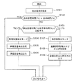
- FIG. 11 is a flowchart showing a detection sequence for detecting capacitance and pressure at each detection point in the hybrid touch panel of the second embodiment.
- step 101 the charge / discharge waveform (Va) is formed by the charge / discharge waveform forming unit 13 as described above.
- the detected discharge time (Td) in the formed charge / discharge waveform is compared with the reference time (To).
- the reference time (To) is the discharge time (Tb) in the non-operation state (see (a) of FIG. 10) in the hybrid touch panel, and is set using the time measured in the non-operation state.
- step 102 if the detected discharge time (Td) is substantially the same as the reference time (To), it is determined that there is no operation and the process returns to step 101 (S101).
- step 103 if the detected discharge time (Td) is longer than the reference time (To) by a certain period or longer, it is determined that the proximity state is present, and the process proceeds to the capacitance detection mode (S104). On the other hand, if the detected discharge time (Td) is shorter than the reference time (To) by a certain period or more, it is determined that the state is a pressing load state, and the process proceeds to the resistance value detection mode (S107).
- a capacitance detection process (S105) for detecting a change in capacitance (C + Cx: see FIG. 8) is performed based on the detected discharge time (Td).
- a capacitance detection output (S106) is performed based on the change in capacitance. That is, an operation state indicating whether or not the detection point has been operated is detected. After performing the capacitance detection output (S106), the same detection sequence is performed by moving to the next detection point in the operation target region.
- step 103 when the detected discharge time Td is shorter than the reference time To (Td ⁇ To), the resistance value detection mode (S107) is performed.
- this resistance value detection mode (S107) based on the detected discharge time (Td), a change in the resistance value (R ⁇ Rx / R + Rx: see FIG. 8) is detected to perform coordinate calculation processing and pressure calculation processing (S108). Is done.
- this coordinate calculation processing one end of one of the opposing electrodes is connected to the input end of the detection circuit 50 constituted by the charge / discharge waveform forming unit 13 and the charge / discharge waveform calculating unit 14, and the other electrode
- the resistance value including the change of the pressure sensitive layer 5 can be measured by grounding one end of the pressure sensitive layer 5.
- the switching elements (SwA to SwH) connected to the first electrode lines (A to H) and the second electrode lines (1 to 8) are connected.
- the connected switching elements (Sw1 to Sw8) are sequentially turned on and off (resistance value detection process). Specifically, for example, in a state where one switching element (Sw1) for the lower electrode unit 20 is turned on and the second electrode line (1) is connected to the detection circuit 50, switching for the upper electrode unit 10 is performed. Switching control for once turning on the elements (SwA to SwH) sequentially is performed, and the first electrode lines (A to H) in the upper electrode portion 10 are sequentially connected to the detection circuit 50. Thus, by connecting the first electrode lines (A to H) to the detection circuit 50, the resistance values of all the first electrode lines (A to H) with respect to the second electrode line (1) are detected. Is detected.
- step 109 a signal indicating the detected coordinate position (operation position) and pressing force (operation pressure) to the control unit (not shown) of the portable electronic device provided with the hybrid touch panel. Is output.
- the process proceeds to a detection sequence for the next detection point.
- release detection is performed at all detection points in the operation target area.
- This release detection compares the detected discharge time (Td) with the reference time (Vo) at all detection points. If the detected discharge time (Td) is substantially the same as the reference time (Vo), release detection is performed.
- the detection sequence in the hybrid touch panel ends. On the contrary, when the detected discharge time (Td) and the reference time (Vo) are different, the detection sequence at all detection points in the operation target region is executed again.
- the detection sequence is executed in the hybrid touch panel according to the second embodiment, and the capacitance (operation state), coordinate position (operation position), and pressing force (operation pressure) at all detection points in the operation target region. Each of which is detected.
- Each detected signal is output to a control unit (not shown) of the portable electronic device provided with the hybrid touch panel, and the portable electronic device is controlled.
- the input means is not limited to the finger, and any conductor can be used. Furthermore, even in the case of a non-conductor such as a stylus, coordinates and pressure can be detected by detection using a resistive film digital method, and therefore, an input method is not selected.
- the capacitance detection signal (Cd) detected by the capacitance detection 11 in the input unit 1 and the resistance value detection signal (Rd) detected by the resistance value detection 12 are: Although the example used for the discharge waveform at the time of discharge in the charge / discharge waveform (Va) has been described, the present invention is not limited to this configuration, and the electrostatic capacitance detected by the capacitance detection 11 and the resistance value detection 12.
- the capacitance detection signal (Cd) and the resistance value detection signal (Rd) can also be used for the charging waveform during charging.
- the present invention by using both the charging waveform during charging and the discharging waveform during discharging in the charging / discharging waveform (Va), a more accurate capacitance (operation state), coordinate position (operation position), and It is also possible to detect each pressing force (operation pressure). Even in this case, the capacitance detection signal (Cd) detected by the capacitance detection 11 in the input unit 1 described in the second embodiment and the resistance value detection signal (Rd) detected by the resistance value detection 12. Since the change appears in the charge waveform at the time of charge and the discharge waveform at the time of discharge according to each of the electrostatic capacity (operation state), the coordinate position (operation position) and the pressing force (operation pressure), A phenomenon can be used, and detection with high accuracy is possible.
- the hybrid touch panel having both the configuration of the resistive film type digital (multi-type) touch panel and the configuration of the capacitance type self-type touch panel has been described.
- the capacitance detection signal (Cd) detected by the capacitance detection 11 in the input unit 1 and the resistance value detection signal (Rd) detected by the resistance value detection 12 are It is possible to detect an operation state (operation state) and an operation position (coordinate position) of the input means by detecting a change in the waveform in the charge / discharge waveform (Va).
- the input unit 1 in the hybrid touch panel according to the second embodiment is provided on the liquid crystal screen of the display device and is entirely formed of a light transmissive material, the input unit 1 of the input unit 1 is visually observed on the liquid crystal screen.
- the upper film 2, the upper electrode part 10, the pressure sensitive layer 5, the lower electrode part 20, and the lower film 8 in the input part 1 are formed of a light transmissive material.
- air reffractive index: 1 is provided in the configuration of the second embodiment.
- the liquid layer is, for example, a material having a refractive index close to that of each material in the components of the upper electrode portion 10 and the lower electrode portion 20, that is, having a refractive index higher than that of air, and has fluidity, light transmittance, and electrical insulation. It is preferable to use a material having heat resistance and heat resistance.
- the material of the upper film 2 and the lower film 8 is a general-purpose material such as polyethylene terephthalate, polystyrene resin, polyolefin resin, ABS resin, AS resin, acrylic resin, or AN resin that can be used for a flexible substrate. Resin can be used.
- the thicknesses of the upper electrode portion 10 and the lower electrode portion 20 are set to 5 ⁇ m to 25 ⁇ m, for example.
- a transparent conductive material such as ITO, CNT, or Ag wire ink.
- a metal such as gold, silver, copper, or nickel, or a conductive paste such as carbon.
- the upper electrode part 10 and the lower electrode part 20 can also be formed by attaching a metal foil such as copper or gold. Further, the upper electrode portion 10 and the lower electrode portion 20 are formed by forming an electrode pattern with a resist on an FPC (flexible circuit board) plated with a metal such as copper, and etching a portion of the metal foil that is not protected by the resist. It can also be formed.
- FPC flexible circuit board
- the adhesive 9 is an insulating member that has adhesiveness to bond the upper film 2 and the lower film 8 and holds a gap between the opposing surfaces of the upper electrode portion 10 and the pressure-sensitive layer 5.
- the adhesive 9 is, for example, a double-sided pressure-sensitive adhesive tape in which a pressure-sensitive adhesive such as an acrylic adhesive paste is formed on both surfaces of a core material such as a polyethylene terephthalate film.
- the thickness of the adhesive 9 is set to 5 to 20 ⁇ m, for example.
- the adhesive 9 may be various adhesives such as UV curable resin and thermosetting resin and the thickness may be set to 5 to 20 ⁇ m.
- the hybrid touch panel as an input device detects the capacitance, resistance, and pressure with a simple circuit configuration, and inputs operation state information, operation position information, and operation pressure information to an electronic device.
- Type for example, regardless of whether the input means is a finger or a stylus, it can be input, and various information can be input with high accuracy and quickness by operating a simple input means. It is a hybrid touch panel as an input device.
- the input device is provided in various electronic devices and can input various information with high accuracy and quickly, for example, a personal digital assistant such as a PDA or a handy terminal, an OA such as a copy machine or a facsimile machine. It is useful for electronic devices such as devices, smartphones, mobile phones, portable game devices, electronic dictionaries, car navigation systems, small PCs, and various home appliances.
Landscapes
- Engineering & Computer Science (AREA)
- General Engineering & Computer Science (AREA)
- Theoretical Computer Science (AREA)
- Human Computer Interaction (AREA)
- Physics & Mathematics (AREA)
- General Physics & Mathematics (AREA)
- Position Input By Displaying (AREA)
- Push-Button Switches (AREA)
Abstract
Priority Applications (2)
| Application Number | Priority Date | Filing Date | Title |
|---|---|---|---|
| US14/128,819 US9542031B2 (en) | 2011-06-24 | 2012-06-19 | Input device using detection of both capacitance and pressure, and capacitance-system hybrid touch panel equipped with pressure-sensitive function |
| JP2013521578A JP5755329B2 (ja) | 2011-06-24 | 2012-06-19 | 静電容量及び圧力の検出を併用した入力装置、及び感圧機能付き静電容量方式ハイブリッドタッチパネル |
Applications Claiming Priority (4)
| Application Number | Priority Date | Filing Date | Title |
|---|---|---|---|
| JP2011140931 | 2011-06-24 | ||
| JP2011-140933 | 2011-06-24 | ||
| JP2011-140931 | 2011-06-24 | ||
| JP2011140933 | 2011-06-24 |
Publications (1)
| Publication Number | Publication Date |
|---|---|
| WO2012176748A1 true WO2012176748A1 (fr) | 2012-12-27 |
Family
ID=47422584
Family Applications (1)
| Application Number | Title | Priority Date | Filing Date |
|---|---|---|---|
| PCT/JP2012/065565 Ceased WO2012176748A1 (fr) | 2011-06-24 | 2012-06-19 | Dispositif d'entrée utilisant la détection de capacitance et de pression, et panneau tactile hybride de type capacitance équipé d'une fonction sensible à la pression |
Country Status (4)
| Country | Link |
|---|---|
| US (1) | US9542031B2 (fr) |
| JP (1) | JP5755329B2 (fr) |
| TW (1) | TWI576747B (fr) |
| WO (1) | WO2012176748A1 (fr) |
Cited By (16)
| Publication number | Priority date | Publication date | Assignee | Title |
|---|---|---|---|---|
| JP2014179062A (ja) * | 2013-02-12 | 2014-09-25 | Sony Corp | センサ装置、入力装置及び電子機器 |
| KR20150003657A (ko) * | 2013-07-01 | 2015-01-09 | 한국전자통신연구원 | 2차원 신호 어드레싱 제어 장치 및 그것의 신호 어드레싱 방법 |
| JP2016062595A (ja) * | 2014-09-19 | 2016-04-25 | 株式会社 ハイディープ | スマートフォン |
| US9524070B2 (en) * | 2015-03-23 | 2016-12-20 | Lg Display Co., Ltd. | Touch screen device and method for driving thereof, and portable electronic device comprising the same |
| WO2017082176A1 (fr) * | 2015-11-11 | 2017-05-18 | アルプス電気株式会社 | Dispositif d'entrée et procédé de de pilotage de dispositif d'entrée |
| JP2017092408A (ja) * | 2015-11-17 | 2017-05-25 | 三菱電機株式会社 | 半導体装置の評価装置及び評価方法 |
| JPWO2016056437A1 (ja) * | 2014-10-07 | 2017-06-29 | 株式会社村田製作所 | タッチ式入力装置及びタッチ入力検出方法 |
| JP2017134810A (ja) * | 2016-01-29 | 2017-08-03 | 三星ディスプレイ株式會社Samsung Display Co.,Ltd. | センサー、タッチセンサー及び表示装置 |
| JP2017167694A (ja) * | 2016-03-15 | 2017-09-21 | 株式会社ジャパンディスプレイ | 表示装置及び表示方法 |
| JP2018067323A (ja) * | 2014-08-01 | 2018-04-26 | 株式会社 ハイディープHiDeep Inc. | タッチ入力装置 |
| KR20190044520A (ko) * | 2017-10-20 | 2019-04-30 | 인피니언 테크놀로지스 아게 | 저항성 및 용량성 센서용 판독 회로 |
| JP2019512831A (ja) * | 2016-03-25 | 2019-05-16 | センセル インコーポレイテッドSensel,Inc. | 表面への力の入力の検出および特徴付けのためのシステムおよび方法 |
| JP2019517076A (ja) * | 2016-05-18 | 2019-06-20 | センセル インコーポレイテッドSensel,Inc. | タッチ入力を検出して確認する方法 |
| JP2020522708A (ja) * | 2017-06-06 | 2020-07-30 | インターリンク エレクトロニクス,インコーポレイテッド | マルチモーダルセンシングトランスデューサ |
| JP2022082490A (ja) * | 2020-11-22 | 2022-06-02 | 斉 永岡 | 投影機能、ディスプレイ付きスマートグラス、及び出力端子 |
| DE112022003997T5 (de) | 2021-08-17 | 2024-06-20 | Alps Alpine Co., Ltd. | Eingabevorrichtung und eingabebestimmungsverfahren |
Families Citing this family (39)
| Publication number | Priority date | Publication date | Assignee | Title |
|---|---|---|---|---|
| US20130265256A1 (en) | 2012-04-07 | 2013-10-10 | Cambridge Touch Technologies, Ltd. | Pressure sensing display device |
| TWI493402B (zh) * | 2013-03-01 | 2015-07-21 | Univ Chung Hua | 觸控面板及其製備方法 |
| US9612677B2 (en) | 2013-06-28 | 2017-04-04 | Atmel Corporation | Pseudo driven shield |
| US9471174B2 (en) * | 2013-07-01 | 2016-10-18 | Electronics And Telecommunications Research Institute | Control apparatus and method of addressing two-dimensional signal |
| KR101452302B1 (ko) * | 2013-07-29 | 2014-10-22 | 주식회사 하이딥 | 터치 센서 패널 |
| JP5567727B1 (ja) * | 2013-09-17 | 2014-08-06 | 株式会社フジクラ | 電子機器及び電子機器の制御方法 |
| US9582186B2 (en) * | 2013-12-20 | 2017-02-28 | Mediatek Inc. | Signature verification between a mobile device and a computing device |
| GB2533667B (en) | 2014-12-23 | 2017-07-19 | Cambridge Touch Tech Ltd | Pressure-sensitive touch panel |
| CN107209590B (zh) | 2014-12-23 | 2021-10-15 | 剑桥触控科技有限公司 | 压敏触摸面板 |
| JP6890372B2 (ja) * | 2015-06-08 | 2021-06-18 | アルプスアルパイン株式会社 | 車載入力装置 |
| CN204808275U (zh) * | 2015-06-10 | 2015-11-25 | 宸鸿科技(厦门)有限公司 | 压力感测装置 |
| KR20160149982A (ko) * | 2015-06-18 | 2016-12-28 | 삼성전자주식회사 | 입력장치를 구비한 전자장치 |
| CN105487703A (zh) * | 2015-07-22 | 2016-04-13 | 敦泰电子有限公司 | 压力检测器及其相关的显示模组 |
| TWI557616B (zh) * | 2015-07-28 | 2016-11-11 | 敦泰電子有限公司 | 壓力檢測器及其相關之顯示模組 |
| CN104992627B (zh) * | 2015-07-29 | 2018-11-06 | 敦泰电子有限公司 | 具有压力检测器的显示模块 |
| KR102513385B1 (ko) * | 2015-07-31 | 2023-03-23 | 엘지디스플레이 주식회사 | 터치 패널의 구동 장치 및 이를 포함하는 전자 기기 |
| KR20170019740A (ko) * | 2015-08-12 | 2017-02-22 | 주식회사 동부하이텍 | 터치 센서 검사 장치 |
| CN105389055A (zh) * | 2015-11-19 | 2016-03-09 | 业成光电(深圳)有限公司 | 应用于压力触控感测器之变阻式结构 |
| CN105373281B (zh) * | 2015-12-04 | 2018-12-25 | 京东方科技集团股份有限公司 | 一种触控显示装置及其驱动方法 |
| KR102473527B1 (ko) * | 2015-12-21 | 2022-12-01 | 엘지디스플레이 주식회사 | 전자 기기 |
| US10282046B2 (en) | 2015-12-23 | 2019-05-07 | Cambridge Touch Technologies Ltd. | Pressure-sensitive touch panel |
| GB2544353B (en) | 2015-12-23 | 2018-02-21 | Cambridge Touch Tech Ltd | Pressure-sensitive touch panel |
| CN105717682B (zh) * | 2015-12-31 | 2023-03-21 | 厦门天马微电子有限公司 | 一种触控显示装置 |
| TWI587194B (zh) * | 2016-02-04 | 2017-06-11 | 恆顥科技股份有限公司 | 觸控顯示裝置 |
| TWI581169B (zh) * | 2016-04-28 | 2017-05-01 | 友達光電股份有限公司 | 雙模式電容觸控顯示面板 |
| KR102482398B1 (ko) | 2016-04-29 | 2022-12-27 | 엘지디스플레이 주식회사 | 터치 스크린 장치 및 이를 포함하는 전자 기기 |
| US20180046295A1 (en) * | 2016-08-12 | 2018-02-15 | Hon Hai Precision Industry Co., Ltd. | Touch display device |
| KR102629869B1 (ko) * | 2016-09-27 | 2024-01-30 | 삼성디스플레이 주식회사 | 터치 스크린, 이를 구비하는 표시 장치 및 이의 구동 방법 |
| KR101987363B1 (ko) * | 2016-09-30 | 2019-06-11 | 한국과학기술연구원 | 비연속적 전도성 패턴을 포함하는 압력 센서, 이를 포함하는 디바이스, 및 압력을 감지하는 장치 및 방법 |
| GB2554736B8 (en) * | 2016-10-07 | 2020-02-12 | Touchnetix Ltd | Multi-touch Capacitance Measurements and Displacement Sensing |
| GB2565305A (en) | 2017-08-08 | 2019-02-13 | Cambridge Touch Tech Ltd | Device for processing signals from a pressure-sensing touch panel |
| US11093088B2 (en) | 2017-08-08 | 2021-08-17 | Cambridge Touch Technologies Ltd. | Device for processing signals from a pressure-sensing touch panel |
| US10866675B2 (en) * | 2019-01-29 | 2020-12-15 | Wuhan China Star Optoelectronics Semiconductor Display Technology Co., Ltd. | Force touch display device and force touch control method |
| CN110460327B (zh) * | 2019-08-15 | 2023-11-24 | 上海科世达-华阳汽车电器有限公司 | 一种触摸感应按钮 |
| TWI709068B (zh) * | 2019-08-29 | 2020-11-01 | 華碩電腦股份有限公司 | 電子裝置及其壓感觸控組件 |
| DE102020110601A1 (de) | 2020-04-18 | 2021-10-21 | Higgstec Inc. | Berührungssensor |
| TWI738438B (zh) * | 2020-07-28 | 2021-09-01 | 萬達光電科技股份有限公司 | 觸控感測器的觸控點感知方法 |
| GB2601482B (en) * | 2020-11-27 | 2025-01-22 | Peratech Ip Ltd | Detecting Manually Applied Pressure |
| GB2633843A (en) * | 2023-09-25 | 2025-03-26 | Touchnetix Ltd | Combined touch and displacement sensing |
Citations (4)
| Publication number | Priority date | Publication date | Assignee | Title |
|---|---|---|---|---|
| JP2008152468A (ja) * | 2006-12-15 | 2008-07-03 | Mitsubishi Electric Corp | タッチパネル制御装置 |
| JP2009176245A (ja) * | 2008-01-28 | 2009-08-06 | Sony Corp | 表示入力装置及び電子機器 |
| WO2010074116A1 (fr) * | 2008-12-25 | 2010-07-01 | 日本写真印刷株式会社 | Ecran tactile possédant une fonction de détection de la force de pression et capteur sensible à la pression pour écran tactile |
| JP2010231565A (ja) * | 2009-03-27 | 2010-10-14 | Victor Co Of Japan Ltd | 入力装置及びこれを用いた電子機器 |
Family Cites Families (18)
| Publication number | Priority date | Publication date | Assignee | Title |
|---|---|---|---|---|
| JPH07129308A (ja) * | 1993-10-28 | 1995-05-19 | Pentel Kk | タブレット走査方法 |
| US5914710A (en) * | 1997-08-20 | 1999-06-22 | Ace Cad Enterprise Co., Ltd. | Cordless pointing instrument for graphics tablet |
| US20030034960A1 (en) * | 2001-08-14 | 2003-02-20 | Hung-Yuan Li | Coordinates input device and method for the same |
| JP4280562B2 (ja) * | 2003-06-16 | 2009-06-17 | 株式会社ワコム | 位置指示器 |
| US8063886B2 (en) * | 2006-07-18 | 2011-11-22 | Iee International Electronics & Engineering S.A. | Data input device |
| JP2008098942A (ja) * | 2006-10-11 | 2008-04-24 | Nec Engineering Ltd | 情報表示電話機制御システム,情報表示制御方法およびそのプログラム記録媒体 |
| US8207944B2 (en) * | 2006-12-19 | 2012-06-26 | 3M Innovative Properties Company | Capacitance measuring circuit and method |
| EP2026179A1 (fr) * | 2007-08-10 | 2009-02-18 | IEE International Electronics & Engineering S.A.R.L. | Procédé pour la génération de données d'entrée |
| JP2009175784A (ja) | 2008-01-21 | 2009-08-06 | Mitsubishi Electric Corp | タッチパネル装置 |
| KR20090089254A (ko) | 2008-02-18 | 2009-08-21 | 세이코 엡슨 가부시키가이샤 | 센싱 장치, 표시 장치, 전자 기기 및, 센싱 방법 |
| JP4720833B2 (ja) * | 2008-02-18 | 2011-07-13 | ソニー株式会社 | センシング装置、表示装置、電子機器およびセンシング方法 |
| JP4948471B2 (ja) * | 2008-04-15 | 2012-06-06 | 三菱電機株式会社 | タッチパネル装置 |
| JP2010117842A (ja) | 2008-11-12 | 2010-05-27 | Sharp Corp | 携帯情報端末 |
| JP5396167B2 (ja) | 2009-06-18 | 2014-01-22 | 株式会社ワコム | 指示体検出装置及び指示体検出方法 |
| CN102334088B (zh) * | 2009-07-29 | 2015-04-15 | 阿尔卑斯电气株式会社 | 操作装置 |
| JP5293564B2 (ja) | 2009-11-04 | 2013-09-18 | カシオ計算機株式会社 | タッチパネル付き液晶表示装置とその駆動方法 |
| TWM384361U (en) * | 2010-03-22 | 2010-07-11 | Minlad Invest Ltd | Capacitive touch panel |
| US8599165B2 (en) * | 2010-08-16 | 2013-12-03 | Perceptive Pixel Inc. | Force and true capacitive touch measurement techniques for capacitive touch sensors |
-
2012
- 2012-06-19 JP JP2013521578A patent/JP5755329B2/ja active Active
- 2012-06-19 US US14/128,819 patent/US9542031B2/en active Active
- 2012-06-19 WO PCT/JP2012/065565 patent/WO2012176748A1/fr not_active Ceased
- 2012-06-22 TW TW101122489A patent/TWI576747B/zh active
Patent Citations (4)
| Publication number | Priority date | Publication date | Assignee | Title |
|---|---|---|---|---|
| JP2008152468A (ja) * | 2006-12-15 | 2008-07-03 | Mitsubishi Electric Corp | タッチパネル制御装置 |
| JP2009176245A (ja) * | 2008-01-28 | 2009-08-06 | Sony Corp | 表示入力装置及び電子機器 |
| WO2010074116A1 (fr) * | 2008-12-25 | 2010-07-01 | 日本写真印刷株式会社 | Ecran tactile possédant une fonction de détection de la force de pression et capteur sensible à la pression pour écran tactile |
| JP2010231565A (ja) * | 2009-03-27 | 2010-10-14 | Victor Co Of Japan Ltd | 入力装置及びこれを用いた電子機器 |
Cited By (26)
| Publication number | Priority date | Publication date | Assignee | Title |
|---|---|---|---|---|
| JP2014179062A (ja) * | 2013-02-12 | 2014-09-25 | Sony Corp | センサ装置、入力装置及び電子機器 |
| KR20150003657A (ko) * | 2013-07-01 | 2015-01-09 | 한국전자통신연구원 | 2차원 신호 어드레싱 제어 장치 및 그것의 신호 어드레싱 방법 |
| KR102159554B1 (ko) | 2013-07-01 | 2020-09-24 | 한국전자통신연구원 | 2차원 신호 어드레싱 제어 장치 및 그것의 신호 어드레싱 방법 |
| JP2018067323A (ja) * | 2014-08-01 | 2018-04-26 | 株式会社 ハイディープHiDeep Inc. | タッチ入力装置 |
| CN109901750A (zh) * | 2014-08-01 | 2019-06-18 | 希迪普公司 | 触摸输入设备 |
| CN109901750B (zh) * | 2014-08-01 | 2021-12-07 | 希迪普公司 | 触摸输入设备 |
| JP2016062595A (ja) * | 2014-09-19 | 2016-04-25 | 株式会社 ハイディープ | スマートフォン |
| JPWO2016056437A1 (ja) * | 2014-10-07 | 2017-06-29 | 株式会社村田製作所 | タッチ式入力装置及びタッチ入力検出方法 |
| US9524070B2 (en) * | 2015-03-23 | 2016-12-20 | Lg Display Co., Ltd. | Touch screen device and method for driving thereof, and portable electronic device comprising the same |
| JPWO2017082176A1 (ja) * | 2015-11-11 | 2018-08-02 | アルプス電気株式会社 | 入力装置及び入力装置の駆動方法 |
| US10430006B2 (en) | 2015-11-11 | 2019-10-01 | Alps Alpine Co., Ltd. | Input device and method for driving input device |
| WO2017082176A1 (fr) * | 2015-11-11 | 2017-05-18 | アルプス電気株式会社 | Dispositif d'entrée et procédé de de pilotage de dispositif d'entrée |
| JP2017092408A (ja) * | 2015-11-17 | 2017-05-25 | 三菱電機株式会社 | 半導体装置の評価装置及び評価方法 |
| JP2017134810A (ja) * | 2016-01-29 | 2017-08-03 | 三星ディスプレイ株式會社Samsung Display Co.,Ltd. | センサー、タッチセンサー及び表示装置 |
| JP2017167694A (ja) * | 2016-03-15 | 2017-09-21 | 株式会社ジャパンディスプレイ | 表示装置及び表示方法 |
| JP2019512831A (ja) * | 2016-03-25 | 2019-05-16 | センセル インコーポレイテッドSensel,Inc. | 表面への力の入力の検出および特徴付けのためのシステムおよび方法 |
| JP2021012743A (ja) * | 2016-03-25 | 2021-02-04 | センセル インコーポレイテッドSensel,Inc. | 表面への力の入力の検出および特徴付けのためのシステムおよび方法 |
| JP7159259B2 (ja) | 2016-03-25 | 2022-10-24 | センセル インコーポレイテッド | 表面への力の入力の検出および特徴付けのためのシステムおよび方法 |
| US11635839B2 (en) | 2016-03-25 | 2023-04-25 | Sensel Inc. | System and method for detecting and characterizing force inputs on a surface |
| JP2019517076A (ja) * | 2016-05-18 | 2019-06-20 | センセル インコーポレイテッドSensel,Inc. | タッチ入力を検出して確認する方法 |
| JP2020522708A (ja) * | 2017-06-06 | 2020-07-30 | インターリンク エレクトロニクス,インコーポレイテッド | マルチモーダルセンシングトランスデューサ |
| KR20190044520A (ko) * | 2017-10-20 | 2019-04-30 | 인피니언 테크놀로지스 아게 | 저항성 및 용량성 센서용 판독 회로 |
| KR102630899B1 (ko) * | 2017-10-20 | 2024-01-30 | 인피니언 테크놀로지스 아게 | 저항성 및 용량성 센서용 판독 회로 |
| JP2022082490A (ja) * | 2020-11-22 | 2022-06-02 | 斉 永岡 | 投影機能、ディスプレイ付きスマートグラス、及び出力端子 |
| JP7562061B2 (ja) | 2020-11-22 | 2024-10-07 | 斉 永岡 | 投影機能、ディスプレイ付きスマートグラス、及び出力端子 |
| DE112022003997T5 (de) | 2021-08-17 | 2024-06-20 | Alps Alpine Co., Ltd. | Eingabevorrichtung und eingabebestimmungsverfahren |
Also Published As
| Publication number | Publication date |
|---|---|
| US20140218334A1 (en) | 2014-08-07 |
| US9542031B2 (en) | 2017-01-10 |
| JP5755329B2 (ja) | 2015-07-29 |
| TWI576747B (zh) | 2017-04-01 |
| JPWO2012176748A1 (ja) | 2015-02-23 |
| TW201310316A (zh) | 2013-03-01 |
Similar Documents
| Publication | Publication Date | Title |
|---|---|---|
| JP5755329B2 (ja) | 静電容量及び圧力の検出を併用した入力装置、及び感圧機能付き静電容量方式ハイブリッドタッチパネル | |
| CN112230791B (zh) | 压电片、触摸面板、及输入输出装置 | |
| TWI526885B (zh) | Touch panel and electronic machine with push detection function | |
| CN105975137B (zh) | 一种触控显示面板及触控显示装置 | |
| CN103336603B (zh) | 触控显示装置 | |
| TWI387908B (zh) | 物體位置偵測裝置與方法及應用該物體位置偵測裝置之影像顯示系統 | |
| US8633712B2 (en) | Electronic device and operation detection method | |
| US8723533B2 (en) | Method for detecting pressure on touch sensing element and electronic device using the same | |
| TWI386834B (zh) | 無偏壓駐極體三維多點之觸控裝置 | |
| EP2629075A1 (fr) | Procédé pour déterminer une valeur de détecteur | |
| WO2012176624A1 (fr) | Panneau tactile comprenant une fonction de détection de pression | |
| US20140035653A1 (en) | Capacitance sensing device and touchscreen | |
| JP2018036973A (ja) | 抵抗膜式タッチパネルからのデータ取得方法、及び抵抗膜式タッチパネル装置 | |
| US20120249472A1 (en) | Touch screen system and methods of calculating touch point thereof | |
| JP2015111317A (ja) | タッチセンサ付携帯型装置及び表示装置 | |
| CN101931392B (zh) | 无偏压驻极体三维多点之触控装置 | |
| CN102830887B (zh) | 一种电阻式触摸屏的触摸控制方法及控制电路 | |
| JP2011133987A (ja) | タッチパネル | |
| CN107562277B (zh) | 一种具有压力检测功能的触摸屏以及电子设备 | |
| CN101853117A (zh) | 触摸面板及应用该触摸面板的触摸输入装置 | |
| CN108874223B (zh) | 显示面板及显示装置 | |
| CN203733093U (zh) | 投射式电容触控面板结构 | |
| US9703442B2 (en) | Position detection device | |
| US20150138133A1 (en) | Touchscreen device and method of driving the same | |
| KR101152756B1 (ko) | 저항막 방식 멀티 터치 패널 및 이를 이용한 터치 위치 감지 방법 |
Legal Events
| Date | Code | Title | Description |
|---|---|---|---|
| 121 | Ep: the epo has been informed by wipo that ep was designated in this application |
Ref document number: 12802518 Country of ref document: EP Kind code of ref document: A1 |
|
| ENP | Entry into the national phase |
Ref document number: 2013521578 Country of ref document: JP Kind code of ref document: A |
|
| NENP | Non-entry into the national phase |
Ref country code: DE |
|
| WWE | Wipo information: entry into national phase |
Ref document number: 14128819 Country of ref document: US |
|
| 122 | Ep: pct application non-entry in european phase |
Ref document number: 12802518 Country of ref document: EP Kind code of ref document: A1 |