WO2012176897A1 - コネクタ - Google Patents
コネクタ Download PDFInfo
- Publication number
- WO2012176897A1 WO2012176897A1 PCT/JP2012/066052 JP2012066052W WO2012176897A1 WO 2012176897 A1 WO2012176897 A1 WO 2012176897A1 JP 2012066052 W JP2012066052 W JP 2012066052W WO 2012176897 A1 WO2012176897 A1 WO 2012176897A1
- Authority
- WO
- WIPO (PCT)
- Prior art keywords
- connection
- connector
- connection terminal
- cable
- housing
- Prior art date
- Legal status (The legal status is an assumption and is not a legal conclusion. Google has not performed a legal analysis and makes no representation as to the accuracy of the status listed.)
- Ceased
Links
Images



Classifications
-
- H—ELECTRICITY
- H01—ELECTRIC ELEMENTS
- H01R—ELECTRICALLY-CONDUCTIVE CONNECTIONS; STRUCTURAL ASSOCIATIONS OF A PLURALITY OF MUTUALLY-INSULATED ELECTRICAL CONNECTING ELEMENTS; COUPLING DEVICES; CURRENT COLLECTORS
- H01R13/00—Details of coupling devices of the kinds covered by groups H01R12/70 or H01R24/00 - H01R33/00
- H01R13/46—Bases; Cases
- H01R13/52—Dustproof, splashproof, drip-proof, waterproof, or flameproof cases
- H01R13/5202—Sealing means between parts of housing or between housing part and a wall, e.g. sealing rings
-
- H—ELECTRICITY
- H01—ELECTRIC ELEMENTS
- H01R—ELECTRICALLY-CONDUCTIVE CONNECTIONS; STRUCTURAL ASSOCIATIONS OF A PLURALITY OF MUTUALLY-INSULATED ELECTRICAL CONNECTING ELEMENTS; COUPLING DEVICES; CURRENT COLLECTORS
- H01R13/00—Details of coupling devices of the kinds covered by groups H01R12/70 or H01R24/00 - H01R33/00
- H01R13/46—Bases; Cases
- H01R13/52—Dustproof, splashproof, drip-proof, waterproof, or flameproof cases
- H01R13/5219—Sealing means between coupling parts, e.g. interfacial seal
-
- H—ELECTRICITY
- H01—ELECTRIC ELEMENTS
- H01R—ELECTRICALLY-CONDUCTIVE CONNECTIONS; STRUCTURAL ASSOCIATIONS OF A PLURALITY OF MUTUALLY-INSULATED ELECTRICAL CONNECTING ELEMENTS; COUPLING DEVICES; CURRENT COLLECTORS
- H01R11/00—Individual connecting elements providing two or more spaced connecting locations for conductive members which are, or may be, thereby interconnected, e.g. end pieces for wires or cables supported by the wire or cable and having means for facilitating electrical connection to some other wire, terminal, or conductive member, blocks of binding posts
- H01R11/11—End pieces or tapping pieces for wires, supported by the wire and for facilitating electrical connection to some other wire, terminal or conductive member
- H01R11/32—End pieces with two or more terminations
Definitions
- the present invention relates to a connector for connecting and wiring a cable to a mounting portion of an electronic device or the like.
- Hybrid cars, electric vehicles, and the like are equipped with motors and devices such as inverters that convert DC power from batteries to AC power and supply the motors.
- a connector structure for a device for connecting an electric wire to such a device a terminal block provided in a case of the device and holding a plurality of device-side terminals connected to the device body, and a plurality of wire-side terminals 2.
- Description of the Related Art It is known to include an electric wire side connector that is held by an electric wire side housing, attach the electric wire side connector to a holding base, and connect the electric wire side terminal and the equipment side terminal (see Patent Document 1).
- connection point between the device and the connector needs to have a waterproof structure. For this reason, when the seal member is fitted into the seal groove of the connector and the connector is attached to the device, the seal member is brought into close contact with the device to ensure the sealing performance. Since it is necessary to seal the device over the entire circumference of the mounting location, it is desired to reduce the size of the connector in order to improve the sealing performance.
- the present invention has been made in view of the above-described circumstances, and an object of the present invention is to provide a connector that can be miniaturized and can improve sealing performance with a connection partner.
- the connector according to the present invention is characterized by the following (1) to (3).
- a connection tab portion provided on the connection terminal is a connector connected to a terminal block provided on the connection partner side,
- the connection terminal includes a junction type connection terminal including a plurality of cable connection portions to which a plurality of the cables are connected and one connection tab portion.
- connection terminal is provided integrally with the housing by insert molding.
- the connector having the above configuration (1) since the connector has a joining type connection terminal having a plurality of cable connection portions to which a plurality of cables are connected and one connection tab portion, a connector for holding the connection terminals is provided. Miniaturization can be achieved. In particular, since the number of connection tab portions connected to the terminal block on the connection partner side is reduced, the mounting portion fitted into the attachment hole of the connection partner can be reduced. Thereby, the sealing range with the attachment hole by a sealing member can be decreased, and a sealing performance can be improved. In the connector having the above configuration (2), since the intersections of the junction type connection terminal and the other connection terminals are arranged at different positions in the thickness direction of the housing, the cable connection is ensured while ensuring the insulation between the connection terminals.
- the size in the width direction of the housing which is the arrangement direction of the portions and the connection tab portions, can be suppressed to achieve downsizing.
- the connection terminals are integrally provided in the housing by insert molding, the connection terminals can be reliably held in the housing, and good insulation between the connection terminals can be ensured. it can.
- FIG. 1 is a perspective view of a connector according to an embodiment.
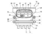
- FIG. 2 is a front view of the connector according to the embodiment.
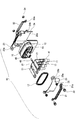
- FIG. 3 is an exploded perspective view seen from the front side of the connector according to the embodiment.
- FIG. 4 is an exploded perspective view seen from the back side of the connector according to the embodiment.
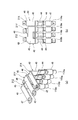
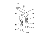
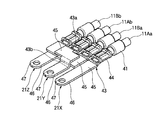
- 5 (a) and 5 (b) are diagrams showing the connection terminals held in the connector housing, and
- FIG. 5 (a) is a perspective view as seen from the front side of the connection terminals, and
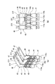
- 6 (a) and 6 (b) are diagrams showing the connection terminals held by the housing of the connector, and
- FIG. 6 (a) is a perspective view as seen from the back side of the connection terminals, and
- FIG. 6 (b). ) Is a rear view of the connection terminal.
- FIG. 7 is a perspective view of the junction type connection terminal as viewed from the back side.
- FIG. 8 is a perspective view of a connection terminal showing a modification of the connection terminal.
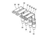
- FIG. 9 is a perspective view of a connector according to a reference example.
- FIG. 10 is a perspective view of a connection terminal according to a reference example.
- FIG. 1 is a perspective view of a connector according to the embodiment
- FIG. 2 is a front view of the connector according to the embodiment
- FIG. 3 is an exploded perspective view as viewed from the front side of the connector according to the embodiment
- Drawing 5 (a) and Drawing 5 (b) are figures showing the connecting terminal held by the housing of a connector
- Drawing 5 (a) is a connection
- FIG. 5B is a front view of the connection terminal
- FIGS. 6A and 6B are views showing the connection terminal held by the housing of the connector.
- 6A is a perspective view as viewed from the back side of the connection terminal
- FIG. 6B is a rear view of the connection terminal
- FIG. 7 is a perspective view as viewed from the back side of the merged connection terminal.
- the connector 10 is a high-voltage connector connected to a motor, an inverter, or the like, and is attached to a case of various devices such as an inverter that is a connection partner to connect the cable 11.
- the connector 10 includes a mounting portion 12 that is fitted into a mounting hole (not shown) formed in a device case, and a cable introduction portion 13 into which a plurality of (four in this example) cables 11 are introduced. It is formed in an L shape in side view.
- the connector 10 includes a housing 15.
- the housing 15 is formed from a synthetic resin, and a plurality of connection terminals 21 are insert-molded.
- a seal groove 16 is formed in the circumferential direction in the mounting portion 12, and an annular seal member 17 is mounted in the seal groove 16.
- Shield shells 23 and 24 made of a metal material are mounted on the housing 15 from the mounting side of the connector 10 to the mounting hole and from the side opposite to the mounting side.
- the shield shells 23 and 24 cover and shield the periphery of the cable introduction portion 13 in the housing 15.
- a fixed piece 23b having a hole 23a is formed in the shield shell 23, and a fixed piece 24b having a screw hole 24a is formed in the shield shell 24, and a screw 26 is inserted into the hole 23a.
- the shield shells 23 and 24 are attached to the cable introduction portion 13 by being screwed into the cable 24a.
- the shield shell 24 is formed with an attachment piece 25 having a hole 25a, and a screw (not shown) is inserted into the hole 25a in a state where the attachment portion 12 of the connector 10 is fitted into the attachment hole of the case of the device. ) And screwed into a screw hole (not shown) on the device side, the shield shell 24 is conductively connected to the case of the device.
- shield bands 31 and 32 made of a metal material are attached to the shield shells 23 and 24 attached to the housing 15 from the attachment side of the connector 10 to the attachment hole and the opposite side to the attachment side. Then, a shield layer (not shown) such as a braid or metal foil provided for shielding the cable 11 is fixed to the shield shells 23 and 24 by these shield bands 31 and 32, and is electrically connected to the shield shells 23 and 24. Is done. Holes 31a and 32a are formed at both ends of the shield bands 31 and 32, and screws 33 are inserted into the holes 31a and 32a and screwed into the nuts 34, thereby shielding the shield bands 31a and 32a. The shield bands 31 and 32 are attached to the shells 23 and 24, and the shield layer of the cable 11 is sandwiched and fixed between the shield shells 23 and 24.
- a shield layer such as a braid or metal foil provided for shielding the cable 11 is fixed to the shield shells 23 and 24 by these shield bands 31 and 32, and is electrically connected to the shield shells 23 and
- the cable 11 is connected to the connection terminal 21 insert-molded in the housing 15.
- the cable 11 has a structure in which a conductor is covered with an insulating resin, and the connection terminal 21 is crimped to an end of the cable 11 to be fixed in a conductive state with the conductor.
- a seal rubber 41 is fixed to the cable 11 in the vicinity of the connection terminal 21 and the connection portion.
- a part of the seal rubber 41 is integrally connected to the housing 15 by insert molding, so that the space between the cable 11 and the housing 15 is securely sealed.
- the cable 11 includes two + pole cables 11Aa and 11Ab having + poles and two ⁇ pole cables 11Ba and 11Bb having ⁇ poles. These positive electrode cables 11Aa and 11Ab and negative electrode cables 11Ba and 11Bb are alternately arranged.
- connection terminal 21 has a bent middle portion and a tip extending toward the mounting side of the connector 10 in the mounting hole.
- the connection terminal 21 has a crimp connection part 43 to which the cable 11 is connected and a connection tab part 46 extending along the mounting part 12.
- the crimp connection portion 43 includes a cable crimp portion (cable connection portion) 44 that crimps and fixes the conductor of the cable 11, and a connecting plate portion 45 between the cable crimp portion 44 and the connection tab portion 46. Further, a fastening hole 47 is formed in the vicinity of the tip of the connection tab portion 46.
- the connection terminal 21 includes two + pole connection terminals 21X and 21Y and one -pole connection terminal 21Z.
- the + pole cables 11Aa and 11Ab are connected to the respective + pole connection terminals 21X and 21Y, and the -pole -Pole cables 11Ba and 11Bb are connected to the connection terminal 21Z.
- the connecting plate portion 45 of the crimp connection portion 43 extends along the cable 11.
- the other positive electrode connection terminal 21 ⁇ / b> Y extends in a direction in which the connecting plate portion 45 of the crimp connection portion 43 is orthogonal to the cable 11.
- a stepped portion 43 a is formed between the cable crimping portion 44 and the connecting plate portion 45.
- the negative electrode connection terminal 21Z has two cable crimping portions 44 arranged with a space therebetween, and these cable crimping portions 44 are connected by a connecting plate portion 45. Yes.
- the connection plate portion 45 in the negative electrode connection terminal 21Z extends in a direction orthogonal to the cable 11, and one connection tab portion 46 extends from the connection plate portion 45.
- the negative electrode connection terminal 21Z is a junction type connection terminal including a plurality of cable crimping portions 44 to which a plurality of cables 11 are connected and one connection tab portion 46.
- the cable crimping portion 44 of the + pole connection terminal 21Y is arranged between the cable crimping portions 44 of the negative electrode connection terminal 21Z, which is a junction type connection terminal.
- the connecting plate portion 45 is disposed on the side opposite to the mounting side of the connector 10 in the mounting hole by the step portion 43a formed between the cable crimping portion 44 and the positive electrode connecting terminal 21Y.
- the intersection of the negative electrode connection terminal 21Z and the positive electrode connection terminal 21Y is the thickness direction of the housing 15 (in other words, the cable crimping portion 44 of the negative electrode connection terminal 21Z and the cable crimping portion 44 of the positive electrode connection terminal 21Y Are arranged at different positions in the direction perpendicular to the planes arranged in parallel.
- the connecting plate portion 45 of the negative electrode connecting terminal 21Z and the connecting plate portion 45 of the positive electrode connecting terminal 21Y are arranged in a spaced state without contacting each other.
- connection terminal 21 including the above-mentioned + pole connection terminals 21X, 21Y and -pole connection terminal 21Z, four cable crimping portions 44 are arranged in parallel at equal intervals, and three connection tab portions 46 are arranged in parallel at equal intervals.
- the housing 15 is insert-molded in a state where it is disposed in the position. And the front-end
- connection terminal 21 When insert-molding the connection terminal 21, first, the cable 11 is crimped and connected to the cable crimping portion 44 of the connection terminal 21, and the seal rubber 41 is provided on the cable 11 by molding. In this state, these connection terminals 21 are set in a molding die of the housing 15 and resin is injection molded into the die. Thereby, the housing 15 in which the connection terminal 21 is insert-molded is obtained.
- connection terminal 21 when the connection terminal 21 is integrated with the housing 15 by insert molding, the resin enters between the connection terminals 21. Thereby, the connection terminal 21 is reliably hold
- the connector 10 is formed with an interlock portion 49 to which the interlock terminal 48 is connected to the mounting portion 12 of the housing 15.
- the mounting portion 12 of the connector 10 is fitted into a mounting hole formed in the case of the device. As described above, when the mounting portion 12 is fitted into the mounting hole of the device panel, the seal member 17 attached to the mounting portion 12 is in close contact with the inner peripheral surface of the mounting hole, and the device and the connector 10 are waterproofed. .
- connection tab part 46 will be connected to the connection terminal of a terminal block, and each cable 11 and the wiring in the apparatus connected to the connection terminal of a terminal block will be conducted.
- a screw is inserted into the hole 25a of the mounting piece 25 of the shield shell 24 and screwed into the screw hole on the device side, and the shield shell 24 is conductively connected to the device case. Then, the shield shells 23 and 24 covering the cable introduction portion 13 arranged outside the device of the connector 10 are conductively connected to the device, and a good shielding effect is obtained.
- the negative electrode connection terminal including the junction type connection terminal having the plurality of cable crimping portions 44 to which the plurality of cables 11 are connected and the one connection tab portion 46. Since 21Z is provided, the housing 15 that holds the connection terminal 21 can be downsized. In particular, since the number of connection tab portions 46 connected to the terminal block on the device side that is the connection partner is reduced, the mounting portion 12 fitted into the attachment hole can be made smaller. Thereby, the sealing range with the attachment hole by the sealing member 17 can be decreased, and a sealing performance can be improved.
- the negative electrode connection terminal 21Z which is a junction type connection terminal and the positive electrode connection terminal 21Y which is another connection terminal are arranged at different positions in the thickness direction of the housing 15, the negative electrode connection terminal 21Z.
- the size of the housing 15 in the width direction, which is the arrangement direction of the connection tab portion 46 and the cable crimping portion 44, can be reduced while ensuring insulation between the positive electrode connection terminal 21 ⁇ / b> Y and the positive electrode connection terminal 21 ⁇ / b> Y.
- connection terminals 21 are integrally provided in the housing 15 by insert molding, the connection terminals 21 can be reliably held in the housing 15, and good insulation between the connection terminals 21 can be ensured.
- each connection terminal 21 has a shape in which the connection tab portion 46 extends along the longitudinal direction of the cable 11 with respect to the crimp connection portion 43.
- the + pole connecting terminal 21Y also forms a step 43b between the connecting plate portion 45 and the connecting tab portion 46, and the + pole connecting terminal with respect to the connecting plate portion 45 of the ⁇ pole connecting terminal 21Z.
- the connecting plate portion 45 of 21Y is arranged in a spaced state without contact.
- FIG. 9 is a perspective view of a connector according to a reference example
- FIG. 10 is a perspective view of a connection terminal according to the reference example.
- the connector 51 has four connection terminals 52, and these connection terminals 52 are introduced by four cables 54 introduced from a cable introduction portion 53. Are connected in parallel and arranged in parallel. And in this connector 51, the connection tab part 56 of the connection terminal 52 protrudes in parallel from the mounting part 55 at intervals.
- connection tab portions 56 of the connection terminals 52 connected to the respective cables 54 are arranged in parallel at intervals, the size of the connector 51 is increased.
- the mounting portion 55 to be fitted into the mounting hole of the device is large, a sealing range with the mounting hole is widened, and there is a possibility that the sealing performance is deteriorated.
- the connector according to the present invention is advantageous in terms of a connector for connecting and wiring a cable to a mounting portion of an electronic device or the like because it can reduce the size and improve the sealing performance with a connection partner.
Landscapes
- Connector Housings Or Holding Contact Members (AREA)
- Manufacturing Of Electrical Connectors (AREA)
Abstract
本発明の目的は、小型化を図り、接続相手とのシール性を高めることが可能なコネクタを提供することにある。 本発明のコネクタは、接続端子(21)が、複数本のケーブル(11)が接続される複数のケーブル圧着部(44)と一つの接続タブ部(46)とを備えた合流型の接続端子である-極接続端子(21Z)を含む。 接続相手側の端子台に接続される接続タブ部(46)の数が少なくされるので、接続相手の取付孔へ嵌め込まれる装着部(12)を小さくすることができる。これにより、シール部材(17)による取付孔とのシール範囲を少なくすることができ、シール性を高めることができる。
Description
本発明は、電子機器等の取付部にケーブルを接続して配線するコネクタに関する。
ハイブリッドカーや電気自動車などには、モータや、このモータにバッテリからの直流電力を交流電力に変換して供給するインバータ等の機器が搭載されている。このような機器に電線を接続するための機器用のコネクタ構造として、機器のケース内に設けられ、機器本体に接続された複数の機器側端子を保持する端子台と、複数の電線側端子を電線側ハウジングに保持させてなる電線側コネクタとを備え、電線側コネクタを保持台に取り付けて、電線側端子と機器側端子を接続するものが知られている(特許文献1参照)。
ところで、機器とコネクタとの接続箇所は、防水構造とする必要がある。このため、コネクタのシール溝にシール部材を嵌め込み、機器へコネクタを装着した際に、シール部材を機器に密着させてシール性を確保している。機器とのシールは、取付箇所の全周にわたって行う必要があるため、シール性を高めるためには、コネクタの小型化を図ることが望まれる。
本発明は、上述した事情に鑑みてなされたものであり、その目的は、小型化を図り、接続相手とのシール性を高めることが可能なコネクタを提供することにある。
前述した目的を達成するために、本発明に係るコネクタは、下記(1)~(3)を特徴としている。
(1) ケーブルが接続された複数の接続端子と、
該接続端子を保持するハウジングと、
接続相手の取付孔へ嵌め込まれる前記ハウジングの一部からなる装着部と、
該装着部に設けられて前記取付孔との間をシールするシール部材とを備え、
前記接続端子に設けられた接続タブ部が前記接続相手側に設けられた端子台に接続されるコネクタであって、
前記接続端子は、複数本の前記ケーブルが接続される複数のケーブル接続部と一つの前記接続タブ部とを備えた合流型の接続端子を含むこと。
(2) 上記(1)の構成のコネクタであって、
前記ケーブル接続部及び前記接続タブ部がそれぞれ前記ハウジングの幅方向に並列に配置され、前記合流型の接続端子と他の接続端子との交差箇所は、前記ハウジングの厚さ方向の異なる位置に配置されていること。
(3) 上記(1)または(2)の構成のコネクタであって、
前記接続端子は、インサート成形によって前記ハウジングに一体的に設けられていること。
(1) ケーブルが接続された複数の接続端子と、
該接続端子を保持するハウジングと、
接続相手の取付孔へ嵌め込まれる前記ハウジングの一部からなる装着部と、
該装着部に設けられて前記取付孔との間をシールするシール部材とを備え、
前記接続端子に設けられた接続タブ部が前記接続相手側に設けられた端子台に接続されるコネクタであって、
前記接続端子は、複数本の前記ケーブルが接続される複数のケーブル接続部と一つの前記接続タブ部とを備えた合流型の接続端子を含むこと。
(2) 上記(1)の構成のコネクタであって、
前記ケーブル接続部及び前記接続タブ部がそれぞれ前記ハウジングの幅方向に並列に配置され、前記合流型の接続端子と他の接続端子との交差箇所は、前記ハウジングの厚さ方向の異なる位置に配置されていること。
(3) 上記(1)または(2)の構成のコネクタであって、
前記接続端子は、インサート成形によって前記ハウジングに一体的に設けられていること。
上記(1)の構成のコネクタでは、複数本のケーブルが接続される複数のケーブル接続部と一つの接続タブ部とを有する合流型の接続端子を備えているので、接続端子を保持するハウジングの小型化を図ることができる。特に、接続相手側の端子台に接続される接続タブ部の数が少なくされるので、接続相手の取付孔へ嵌め込まれる装着部を小さくすることができる。これにより、シール部材による取付孔とのシール範囲を少なくすることができ、シール性を高めることができる。
上記(2)の構成のコネクタでは、合流型の接続端子と他の接続端子との交差箇所をハウジングの厚さ方向の異なる位置に配置したので、接続端子同士の絶縁を確保しつつ、ケーブル接続部及び接続タブ部の配列方向であるハウジングの幅方向の大きさを抑えて小型化を図ることができる。
上記(3)の構成のコネクタでは、インサート成形によってハウジングに接続端子を一体的に設けたので、ハウジングに接続端子を確実に保持させることができ、接続端子同士の良好な絶縁を確保することができる。
上記(2)の構成のコネクタでは、合流型の接続端子と他の接続端子との交差箇所をハウジングの厚さ方向の異なる位置に配置したので、接続端子同士の絶縁を確保しつつ、ケーブル接続部及び接続タブ部の配列方向であるハウジングの幅方向の大きさを抑えて小型化を図ることができる。
上記(3)の構成のコネクタでは、インサート成形によってハウジングに接続端子を一体的に設けたので、ハウジングに接続端子を確実に保持させることができ、接続端子同士の良好な絶縁を確保することができる。
本発明によれば、小型化を図り、接続相手とのシール性を高めることが可能なコネクタを提供できる。
以上、本発明について簡潔に説明した。更に、以下に説明される発明を実施するための形態を添付の図面を参照して通読することにより、本発明の詳細は更に明確化されるであろう。
以下、本発明に係る実施形態の例を、図面を参照して説明する。
図1は、実施形態に係るコネクタの斜視図、図2は、実施形態に係るコネクタの正面図、図3は、実施形態に係るコネクタの正面側から視た分解斜視図、図4は、実施形態に係るコネクタの背面側から視た分解斜視図、図5(a)及び図5(b)は、コネクタのハウジングに保持される接続端子を示す図であって、図5(a)は接続端子の正面側から視た斜視図、図5(b)は接続端子の正面図、図6(a)及び図6(b)は、コネクタのハウジングに保持される接続端子を示す図であって、図6(a)は接続端子の背面側から視た斜視図、図6(b)は接続端子の背面図、図7は、合流型の接続端子の背面側から視た斜視図である。
図1及び図2に示すように、本実施形態に係るコネクタ10は、モータやインバータ等に接続される高圧コネクタであり、接続相手であるインバータ等の各種機器のケースに装着されてケーブル11を接続する。このコネクタ10は、機器のケースに形成された取付孔(図示略)へ嵌め込まれる装着部12と、複数本(本例では4本)のケーブル11が導入されるケーブル導入部13とを有しており、側面視でL字状に形成されている。
図3及び図4に示すように、コネクタ10は、ハウジング15を備えている。このハウジング15は、合成樹脂から成形されたもので、複数の接続端子21がインサート成形されている。
ハウジング15には、装着部12に、周方向へわたってシール溝16が形成されており、このシール溝16には、環状に形成されたシール部材17が装着される。
ハウジング15には、取付孔へのコネクタ10の装着側及び装着側と反対側から、金属材料から形成されたシールドシェル23,24が装着されている。そして、これらのシールドシェル23,24によって、ハウジング15におけるケーブル導入部13の周囲が覆われてシールドされている。シールドシェル23には、孔部23aを有する固定片23bが形成され、シールドシェル24には、ネジ孔24aを有する固定片24bが形成されており、孔部23aにネジ26を挿入し、ネジ孔24aへ螺合させることにより、シールドシェル23,24がケーブル導入部13に装着される。
また、シールドシェル24には、孔部25aを有する取付片25が形成されており、コネクタ10の装着部12を機器のケースの取付孔へ嵌め込んだ状態で、孔部25aへネジ(図示略)を挿入し、機器側のネジ孔(図示略)へねじ込むことにより、シールドシェル24が機器のケースに導通接続される。
また、ハウジング15に装着されたシールドシェル23,24には、取付孔へのコネクタ10の装着側及び装着側と反対側から、金属材料から形成されたシールドバンド31,32が装着されている。そして、これらのシールドバンド31,32によって、シールドシェル23,24にケーブル11のシールドのために設けられた編組または金属箔等のシールド層(図示略)が固定され、シールドシェル23,24に導通される。これらのシールドバンド31,32には、その両端部に、孔部31a,32aが形成されており、これらの孔部31a,32aにネジ33を挿入し、ナット34へ螺合させることにより、シールドシェル23,24にシールドバンド31,32が装着され、ケーブル11のシールド層がシールドシェル23,24との間で挟持されて固定される。
ハウジング15にインサート成形される接続端子21には、ケーブル11が接続されている。ケーブル11は、導体を絶縁樹脂によって被覆した構造を有しており、このケーブル11の端部に接続端子21を圧着することにより、導体と導通した状態で固定されている。
また、ケーブル11には、接続端子21と接続箇所の近傍に、シールゴム41が固定されている。このシールゴム41は、その一部がハウジング15にインサート成形によって一体的に連結され、これにより、ケーブル11とハウジング15との間が確実にシールされている。
図5(a)~図6(b)に示すように、ケーブル11は、+極の2本の+極ケーブル11Aa,11Abと、-極の2本の-極ケーブル11Ba,11Bbとを有しており、これらの+極ケーブル11Aa,11Abと-極ケーブル11Ba,11Bbとが交互に配列されている。
接続端子21は、中間部が屈曲されて先端が取付孔へのコネクタ10の装着側へ向かって延在されている。これにより、接続端子21は、ケーブル11が接続される圧着接続部43と、装着部12に沿って延在する接続タブ部46とを有している。圧着接続部43は、ケーブル11の導体を圧着固定するケーブル圧着部(ケーブル接続部)44と、このケーブル圧着部44と接続タブ部46との間の連結板部45とを有している。また、接続タブ部46には、その先端近傍に、締結用孔部47が形成されている。
接続端子21は、2つの+極接続端子21X,21Yと一つの-極接続端子21Zとからなるもので、それぞれの+極接続端子21X,21Yに+極ケーブル11Aa,11Abが接続され、-極接続端子21Zに-極ケーブル11Ba,11Bbが接続されている。
一方の+極接続端子21Xは、圧着接続部43の連結板部45が、ケーブル11に沿って延在されている。これに対して、他方の+極接続端子21Yは、圧着接続部43の連結板部45がケーブル11に対して直交する方向へ延在されている。また、この+極接続端子21Yの圧着接続部43は、ケーブル圧着部44と連結板部45との間に、段部43aが形成されている。これにより、+極接続端子21Yの連結板部45が取付孔へのコネクタ10の装着側と反対側に配置されている。すなわち、+極接続端子21Yの連結板部45が、-極接続端子21Zの連結板部45における接続タブ部46とは反対の背面側に配置されている。
また、図7に示すように、-極接続端子21Zは、間隔をあけて配置された二つのケーブル圧着部44を有しており、これらのケーブル圧着部44が連結板部45によって連結されている。この-極接続端子21Zにおける連結板部45は、ケーブル11に対して直交する方向へ延在されており、この連結板部45から一つの接続タブ部46が延在されている。このように、この-極接続端子21Zは、複数本のケーブル11が接続される複数のケーブル圧着部44と一つの接続タブ部46とを備えた合流型の接続端子である。
そして、この合流型の接続端子である-極接続端子21Zにおけるケーブル圧着部44の間に、+極接続端子21Yのケーブル圧着部44が配置されている。ここで、+極接続端子21Yでは、ケーブル圧着部44との間に形成された段部43aによって連結板部45が取付孔へのコネクタ10の装着側と反対側に配置されている。つまり、-極接続端子21Zと+極接続端子21Yとの交差箇所がハウジング15の厚さ方向(言い換えれば、-極接続端子21Zのケーブル圧着部44と+極接続端子21Yのケーブル圧着部44とが並列に配置された平面に対して垂直な方向)の異なる位置に配置されている。これにより、-極接続端子21Zの連結板部45と+極接続端子21Yの連結板部45は、互いに接触することなく、間隔をあけた状態に配置される。
上記の+極接続端子21X,21Y及び-極接続端子21Zからなる接続端子21は、4つのケーブル圧着部44が等間隔に並列に配置され、また、3つの接続タブ部46が等間隔に並列に配置された状態でハウジング15にインサート成形されている。そして、これらの接続端子21の各接続タブ部46の締結用孔部47を有する先端部が、ハウジング15の装着部12から突出されている。
接続端子21をインサート成形する場合、まず、接続端子21のケーブル圧着部44にケーブル11を圧着して接続し、ケーブル11にシールゴム41を成形によって設ける。その状態で、これらの接続端子21をハウジング15の成形用金型にセットし、金型へ樹脂を射出成形する。これにより、接続端子21がインサート成形されたハウジング15が得られる。
このように、接続端子21をインサート成形によってハウジング15に一体化すると、各接続端子21の間に樹脂が入り込むこととなる。これにより、接続端子21は、ハウジング15に確実に保持され、また、各接続端子21同士の間では、沿面距離等を考慮することなく、絶縁が確保される。
また、コネクタ10には、ハウジング15の装着部12に、インターロック端子48が接続されるインターロック部49が成形されている。
上記構造のコネクタ10を機器に接続するには、コネクタ10の装着部12を機器のケースに形成された取付孔へ嵌め込む。このように、機器のパネルの取付孔へ装着部12を嵌め込むと、装着部12に取り付けられているシール部材17が取付孔の内周面に密着し、機器とコネクタ10とが防水される。
そして、装着部12から突出されている3つの接続タブ部46の締結用孔部47に締結ボルト(図示略)を挿入し、この締結ボルトを機器の内部に設けられた端子台の接続端子(図示略)にねじ込む。このようにすると、接続タブ部46が端子台の接続端子に接続され、各ケーブル11と端子台の接続端子に接続された機器内の配線とが導通される。
さらに、シールドシェル24の取付片25の孔部25aへネジを挿入し、機器側のネジ孔へねじ込み、シールドシェル24を機器のケースに導通接続させる。すると、コネクタ10の機器の外側に配置されるケーブル導入部13を覆うシールドシェル23,24が機器に導通接続され、良好なシールド効果が得られる。
このように、上記実施形態に係るコネクタによれば、複数本のケーブル11が接続される複数のケーブル圧着部44と一つの接続タブ部46とを有する合流型の接続端子からなる-極接続端子21Zを備えているので、接続端子21を保持するハウジング15の小型化を図ることができる。特に、接続相手である機器側の端子台に接続される接続タブ部46の数が少なくされるので、取付孔へ嵌め込まれる装着部12を小さくすることができる。これにより、シール部材17による取付孔とのシール範囲を少なくすることができ、シール性を高めることができる。
また、合流型の接続端子である-極接続端子21Zと他の接続端子である+極接続端子21Yとの交差箇所をハウジング15の厚さ方向の異なる位置に配置したので、-極接続端子21Zと+極接続端子21Yとの絶縁を確保しつつ、接続タブ部46及びケーブル圧着部44の配列方向であるハウジング15の幅方向の大きさを抑えて小型化を図ることができる。
しかも、インサート成形によってハウジング15に接続端子21を一体的に設けたので、ハウジング15に接続端子21を確実に保持させることができ、接続端子21同士の良好な絶縁を確保することができる。
なお、上記実施形態では、装着部12とケーブル導入部13とが側面視でL字状に形成されたコネクタを例示したが、装着部12とケーブル導入部13とは、直線状に形成されていても良い。この場合、図8に示すように、各接続端子21は、圧着接続部43に対して接続タブ部46がケーブル11の長手方向に沿って延在する形状となる。また、この場合、+極接続端子21Yは、連結板部45と接続タブ部46との間にも段部43bを形成し、-極接続端子21Zの連結板部45に対して+極接続端子21Yの連結板部45が接触することなく、間隔をあけた状態に配置されるようにする。
ここで、本発明の更なる優位性を説明するため、図9及び図10に参考例を示す。
図9は、参考例に係るコネクタの斜視図、図10は参考例に係る接続端子の斜視図である。
図9及び図10に示すように、この参考例に係るコネクタ51は、4つの接続端子52を有しており、これらの接続端子52が、ケーブル導入部53から導入される4本のケーブル54にそれぞれ接続されて並列に配置されている。そして、このコネクタ51では、装着部55から接続端子52の接続タブ部56が間隔をあけて並列に突出されている。
このようなコネクタ51では、それぞれのケーブル54に接続された接続端子52の接続タブ部56が間隔をあけて並列に配置されているので、大型化を招いてしまう。特に、機器の取付孔へ嵌め込まれる装着部55が大型であるため、取付孔とのシール範囲が広くなり、シール性の低下を招くおそれがある。
尚、本発明は、上述した実施形態に限定されるものではなく、適宜、変形、改良、等が可能である。その他、上述した実施形態における各構成要素の材質、形状、寸法、数、配置箇所、等は本発明を達成できるものであれば任意であり、限定されない。
本発明を詳細にまた特定の実施態様を参照して説明したが、本発明の精神と範囲を逸脱することなく様々な変更や修正を加えることができることは当業者にとって明らかである。
本出願は、2011年6月23日出願の日本特許出願(特願2011-139425)に基づくものであり、その内容はここに参照として取り込まれる。
本発明のコネクタは、小型化を図り、接続相手とのシール性を高めることができるという効果を奏し、電子機器等の取付部にケーブルを接続して配線するコネクタに関して有用である。
10 コネクタ
11 ケーブル
11Aa,11Ab +極ケーブル(ケーブル)
11Ba,11Bb -極ケーブル(ケーブル)
12 装着部
15 ハウジング
17 シール部材
21 接続端子
21X,21Y +極接続端子(接続端子)
21Z -極接続端子(接続端子)
44 ケーブル圧着部(ケーブル接続部)
46 接続タブ部
11 ケーブル
11Aa,11Ab +極ケーブル(ケーブル)
11Ba,11Bb -極ケーブル(ケーブル)
12 装着部
15 ハウジング
17 シール部材
21 接続端子
21X,21Y +極接続端子(接続端子)
21Z -極接続端子(接続端子)
44 ケーブル圧着部(ケーブル接続部)
46 接続タブ部
Claims (3)
- ケーブルが接続された複数の接続端子と、
該接続端子を保持するハウジングと、
接続相手の取付孔へ嵌め込まれる前記ハウジングの一部からなる装着部と、
該装着部に設けられて前記取付孔との間をシールするシール部材とを備え、
前記接続端子に設けられた接続タブ部が前記接続相手側に設けられた端子台に接続されるコネクタであって、
前記接続端子は、複数本の前記ケーブルが接続される複数のケーブル接続部と一つの前記接続タブ部とを備えた合流型の接続端子を含むコネクタ。 - 前記ケーブル接続部及び前記接続タブ部がそれぞれ前記ハウジングの幅方向に並列に配置され、前記合流型の接続端子と他の接続端子との交差箇所は、前記ハウジングの厚さ方向の異なる位置に配置されている請求項1に記載のコネクタ。
- 前記接続端子は、インサート成形によって前記ハウジングに一体的に設けられている請求項1または請求項2に記載のコネクタ。
Priority Applications (3)
| Application Number | Priority Date | Filing Date | Title |
|---|---|---|---|
| CN201280030933.4A CN103620880B (zh) | 2011-06-23 | 2012-06-22 | 连接器 |
| EP12801813.2A EP2725661B1 (en) | 2011-06-23 | 2012-06-22 | Connector |
| US14/136,517 US9083107B2 (en) | 2011-06-23 | 2013-12-20 | Connector |
Applications Claiming Priority (2)
| Application Number | Priority Date | Filing Date | Title |
|---|---|---|---|
| JP2011-139425 | 2011-06-23 | ||
| JP2011139425A JP5743740B2 (ja) | 2011-06-23 | 2011-06-23 | コネクタ |
Related Child Applications (1)
| Application Number | Title | Priority Date | Filing Date |
|---|---|---|---|
| US14/136,517 Continuation US9083107B2 (en) | 2011-06-23 | 2013-12-20 | Connector |
Publications (1)
| Publication Number | Publication Date |
|---|---|
| WO2012176897A1 true WO2012176897A1 (ja) | 2012-12-27 |
Family
ID=47422724
Family Applications (1)
| Application Number | Title | Priority Date | Filing Date |
|---|---|---|---|
| PCT/JP2012/066052 Ceased WO2012176897A1 (ja) | 2011-06-23 | 2012-06-22 | コネクタ |
Country Status (5)
| Country | Link |
|---|---|
| US (1) | US9083107B2 (ja) |
| EP (1) | EP2725661B1 (ja) |
| JP (1) | JP5743740B2 (ja) |
| CN (1) | CN103620880B (ja) |
| WO (1) | WO2012176897A1 (ja) |
Cited By (3)
| Publication number | Priority date | Publication date | Assignee | Title |
|---|---|---|---|---|
| CN111016823A (zh) * | 2018-10-09 | 2020-04-17 | 本田技研工业株式会社 | 接头及车辆 |
| WO2020129676A1 (ja) * | 2018-12-20 | 2020-06-25 | 住友電装株式会社 | コネクタ対及びコネクタ付き電線 |
| WO2020166312A1 (ja) * | 2019-02-13 | 2020-08-20 | 株式会社オートネットワーク技術研究所 | コネクタ装置 |
Families Citing this family (38)
| Publication number | Priority date | Publication date | Assignee | Title |
|---|---|---|---|---|
| JP5751875B2 (ja) * | 2011-03-22 | 2015-07-22 | 矢崎総業株式会社 | シールドコネクタ |
| US9318849B2 (en) * | 2011-04-14 | 2016-04-19 | Yazaki Corporation | Shielded connector |
| JP5743740B2 (ja) * | 2011-06-23 | 2015-07-01 | 矢崎総業株式会社 | コネクタ |
| JP5939177B2 (ja) * | 2013-03-01 | 2016-06-22 | 株式会社オートネットワーク技術研究所 | ワイヤハーネス |
| US8956186B2 (en) * | 2013-03-13 | 2015-02-17 | Tyco Electronics Corporation | Right angle header assembly |
| JP6009986B2 (ja) | 2013-04-24 | 2016-10-19 | 矢崎総業株式会社 | 電線のコネクタ構造 |
| JP6200322B2 (ja) * | 2013-12-26 | 2017-09-20 | 矢崎総業株式会社 | コネクタ |
| JP6076505B2 (ja) * | 2014-01-20 | 2017-02-08 | 矢崎総業株式会社 | 活電部保護構造及びコネクタ |
| CN103812077A (zh) * | 2014-02-17 | 2014-05-21 | 宁德时代新能源科技有限公司 | 一种电缆连接装置 |
| KR102188135B1 (ko) * | 2014-04-14 | 2020-12-07 | 엘에스이브이코리아 주식회사 | 전기자동차용 전력 차단 시스템 |
| JP6269418B2 (ja) * | 2014-09-29 | 2018-01-31 | 株式会社オートネットワーク技術研究所 | 機器用コネクタ |
| CN116435805A (zh) * | 2014-10-27 | 2023-07-14 | 安费诺富加宜(亚洲)私人有限公司 | 圆形电源连接器 |
| JP6319633B2 (ja) * | 2015-01-28 | 2018-05-09 | 住友電装株式会社 | 機器用コネクタ |
| JP6492929B2 (ja) * | 2015-04-23 | 2019-04-03 | 住友電装株式会社 | コネクタ |
| JP6545529B2 (ja) * | 2015-05-26 | 2019-07-17 | 住友電装株式会社 | 防水コネクタ |
| DE102015213439A1 (de) * | 2015-07-17 | 2017-01-19 | Zf Friedrichshafen Ag | Leistungsanschluss für ein elektrisches Gerät, insbesondere für eine elektrische Maschine zum Antreiben eines Kraftfahrzeuges |
| JP6141363B2 (ja) * | 2015-07-22 | 2017-06-07 | 住友電装株式会社 | シールドコネクタ |
| JP6205397B2 (ja) * | 2015-10-28 | 2017-09-27 | 住友電装株式会社 | シールドコネクタ |
| JP6459942B2 (ja) * | 2015-12-10 | 2019-01-30 | 住友電装株式会社 | シールドシェル及びシールドコネクタ |
| ITUB20159751A1 (it) * | 2015-12-30 | 2017-06-30 | Johnson Electric Asti S R L | Cablaggio con connettore integrato, particolarmente per autoveicoli. |
| CN106450833B (zh) * | 2016-11-08 | 2019-01-08 | 四川永贵科技有限公司 | 电机及电机控制器用弯式多芯连接器 |
| JP6550095B2 (ja) * | 2017-06-14 | 2019-07-24 | 矢崎総業株式会社 | 樹脂入りパッキン及び防水コネクタ |
| FR3073096B1 (fr) * | 2017-10-26 | 2019-11-08 | Valeo Siemens Eautomotive France Sas | Barre d'isolation electrique, notamment pour un module electronique de puissance d'un onduleur |
| JP6616815B2 (ja) * | 2017-12-20 | 2019-12-04 | 矢崎総業株式会社 | コネクタ及びコネクタ付き電線 |
| US11339823B2 (en) * | 2018-08-09 | 2022-05-24 | J.S.T. Corporation | System and method for sealing a metal fastener from electrolyte in an area of dissimilar metals |
| US10923863B2 (en) * | 2018-12-04 | 2021-02-16 | J.S.T. Corporation | High voltage connector and method for assembling thereof |
| JP6894934B2 (ja) * | 2019-03-11 | 2021-06-30 | 矢崎総業株式会社 | コネクタ |
| JP6898380B2 (ja) * | 2019-04-04 | 2021-07-07 | 矢崎総業株式会社 | コネクタ |
| JP7005119B2 (ja) * | 2019-07-29 | 2022-01-21 | 矢崎総業株式会社 | コネクタ |
| KR102805462B1 (ko) * | 2019-12-04 | 2025-05-09 | 현대자동차주식회사 | 커넥터와 센서 유닛의 결합체 |
| JP7066760B2 (ja) * | 2020-01-08 | 2022-05-13 | 矢崎総業株式会社 | 導体の接続構造 |
| JP7155207B2 (ja) * | 2020-08-13 | 2022-10-18 | 矢崎総業株式会社 | コネクタ |
| CN114665320B (zh) * | 2020-12-23 | 2025-01-14 | 安波福连接器系统(南通)有限公司 | 直角连接器和连接器组件 |
| KR102522790B1 (ko) * | 2021-02-01 | 2023-04-18 | 주식회사 센서뷰 | Emi차폐 기능을 갖는 전기 커넥터 |
| JP7563231B2 (ja) * | 2021-02-25 | 2024-10-08 | 住友電装株式会社 | コネクタ |
| US12525755B2 (en) | 2021-07-19 | 2026-01-13 | Fci Usa Llc | Power connector for compact electronic systems |
| JP7393402B2 (ja) * | 2021-09-16 | 2023-12-06 | 矢崎総業株式会社 | 端子台 |
| CN115911993A (zh) * | 2022-11-23 | 2023-04-04 | 中航光电科技股份有限公司 | 线缆转接器及线缆组件 |
Citations (4)
| Publication number | Priority date | Publication date | Assignee | Title |
|---|---|---|---|---|
| JPS55142892U (ja) * | 1979-03-31 | 1980-10-13 | ||
| JPH0256367U (ja) * | 1988-10-18 | 1990-04-24 | ||
| JP2002246104A (ja) * | 2001-02-15 | 2002-08-30 | Auto Network Gijutsu Kenkyusho:Kk | 防水コネクタ |
| JP2006031962A (ja) | 2004-07-12 | 2006-02-02 | Auto Network Gijutsu Kenkyusho:Kk | 機器用コネクタ |
Family Cites Families (75)
| Publication number | Priority date | Publication date | Assignee | Title |
|---|---|---|---|---|
| GB412985A (en) | 1933-01-06 | 1934-07-06 | Elisha Mander Ltd | Improvements in, or relating to, photograph and similar frames |
| JPS4717382Y1 (ja) * | 1971-08-14 | 1972-06-16 | ||
| US4354726A (en) * | 1979-03-20 | 1982-10-19 | Nissan Motor Company, Limited | Battery terminal connector with an uneven interior surface |
| JPS55142892A (en) | 1979-04-19 | 1980-11-07 | Marugo Kiso Kogyo Kk | Tippwidthhincreased drilling bucket for field pile driving method |
| US5171169A (en) * | 1991-11-21 | 1992-12-15 | Scosche Industries, Inc. | Disconnectible electrical connection system |
| US5599210A (en) * | 1993-06-17 | 1997-02-04 | Green; Charles L. | Battery terminal connector |
| US5688131A (en) * | 1996-09-03 | 1997-11-18 | Wirth Co Engineering, Inc. | Multi-use electrical connector |
| TW417339B (en) * | 1998-12-11 | 2001-01-01 | Hon Hai Precsion Industry Co L | Trimming connection method for cables and the device thereof |
| JP4225444B2 (ja) * | 1999-09-13 | 2009-02-18 | Obara株式会社 | 溶接用ケ―ブル |
| US6322376B1 (en) * | 2000-03-31 | 2001-11-27 | Yazaki North America | Stud bolt holder for a power distribution box |
| US6334797B1 (en) * | 2000-08-31 | 2002-01-01 | Shih-Tsung Liang | Battery terminal connector |
| US6364720B1 (en) * | 2000-12-18 | 2002-04-02 | Shih-Tsung Liang | Battery terminal connector |
| JP3952439B2 (ja) * | 2001-03-26 | 2007-08-01 | 矢崎総業株式会社 | 電磁波シールド構造 |
| GB2382235B (en) * | 2001-11-20 | 2005-06-22 | Shih-Tsung Liang | Battery terminal connector |
| JP3928483B2 (ja) * | 2002-05-29 | 2007-06-13 | 住友電装株式会社 | 分割コネクタ |
| US6764353B2 (en) * | 2002-06-21 | 2004-07-20 | Royal Die & Stamping Co., Inc. | Battery terminal connector |
| JP3985630B2 (ja) * | 2002-08-19 | 2007-10-03 | 住友電装株式会社 | 電気接続箱および該電気接続箱の組立方法 |
| DE10338299A1 (de) * | 2002-08-22 | 2004-04-22 | Sumitomo Wiring Systems, Ltd., Yokkaichi | Anschlußpaßstück |
| JP3947093B2 (ja) * | 2002-11-21 | 2007-07-18 | 株式会社オートネットワーク技術研究所 | 機器用コネクタ |
| JP2004172476A (ja) * | 2002-11-21 | 2004-06-17 | Auto Network Gijutsu Kenkyusho:Kk | シールド機能を備えた導電路 |
| JP2004349026A (ja) * | 2003-05-20 | 2004-12-09 | Yazaki Corp | ホルダ及びコネクタ |
| JP4046033B2 (ja) * | 2003-07-30 | 2008-02-13 | 住友電装株式会社 | 自動車用電気接続箱におけるバスバーの半嵌合検知構造 |
| GB0412985D0 (en) * | 2004-06-11 | 2004-07-14 | Delphi Tech Inc | Electrical ring terminal assembly |
| JP4551166B2 (ja) * | 2004-09-13 | 2010-09-22 | 矢崎総業株式会社 | 機器直付けコネクタ |
| JP4235185B2 (ja) * | 2005-02-24 | 2009-03-11 | 矢崎総業株式会社 | アースプレート及びこれに同軸線を取り付けるための治具 |
| JP4729416B2 (ja) * | 2006-02-24 | 2011-07-20 | 株式会社オートネットワーク技術研究所 | コネクタ |
| EP1883135A1 (en) * | 2006-07-28 | 2008-01-30 | Tyco Electronics AMP Italia S.p.A. | Electrical connector |
| US7422491B2 (en) * | 2006-10-19 | 2008-09-09 | Tyco Electronics Corporation | Bussing connector |
| US7351123B1 (en) * | 2007-02-21 | 2008-04-01 | Devin Winiecke | Electrical terminal splice |
| JP5194609B2 (ja) * | 2007-07-26 | 2013-05-08 | 住友電装株式会社 | 機器用コネクタ |
| JP5119847B2 (ja) * | 2007-10-12 | 2013-01-16 | 住友電装株式会社 | コネクタ |
| US7438605B1 (en) * | 2008-01-08 | 2008-10-21 | Universal Scientific Industrial Co., Ltd | Wire connecting device |
| JP5095446B2 (ja) * | 2008-03-05 | 2012-12-12 | 矢崎総業株式会社 | コネクタ |
| US7591660B1 (en) * | 2008-04-03 | 2009-09-22 | Gm Global Technology Operations, Inc. | Bi-directional lug connection and method |
| JP5046043B2 (ja) * | 2008-07-10 | 2012-10-10 | 住友電装株式会社 | コネクタ |
| US7597580B1 (en) * | 2008-09-17 | 2009-10-06 | Yazaki North America, Inc. | Connector with terminal motion reduction |
| JP2010123291A (ja) * | 2008-11-17 | 2010-06-03 | Chugoku Electric Power Co Inc:The | 圧着端子 |
| JP5240522B2 (ja) * | 2009-04-13 | 2013-07-17 | 住友電装株式会社 | コネクタ |
| JP5399804B2 (ja) * | 2009-08-03 | 2014-01-29 | 矢崎総業株式会社 | コネクタ |
| JP5698451B2 (ja) * | 2009-10-05 | 2015-04-08 | 矢崎総業株式会社 | 端子台 |
| US8648507B2 (en) * | 2009-10-05 | 2014-02-11 | Remy Technologies, L.L.C. | Stator assembly including a terminal block for an electric machine |
| JP5233959B2 (ja) * | 2009-11-05 | 2013-07-10 | 住友電装株式会社 | 機器用コネクタ |
| JP5370767B2 (ja) * | 2009-11-10 | 2013-12-18 | 住友電装株式会社 | ジョイントコネクタ及びワイヤハーネス |
| JP5233962B2 (ja) * | 2009-11-10 | 2013-07-10 | 住友電装株式会社 | ジョイントコネクタ及びワイヤハーネス |
| JP5467850B2 (ja) * | 2009-12-03 | 2014-04-09 | 矢崎総業株式会社 | L字型コネクタ |
| DE202009016970U1 (de) * | 2009-12-16 | 2011-04-28 | Huber + Suhner Ag | Verbindungsvorrichtung |
| JP2011154864A (ja) * | 2010-01-27 | 2011-08-11 | Yazaki Corp | コネクタ |
| JP5485731B2 (ja) * | 2010-02-02 | 2014-05-07 | 矢崎総業株式会社 | 防水型シールドコネクタ |
| JP5524687B2 (ja) * | 2010-04-13 | 2014-06-18 | 矢崎総業株式会社 | コネクタ |
| JP5494236B2 (ja) * | 2010-05-28 | 2014-05-14 | 株式会社オートネットワーク技術研究所 | アース接続装置およびそれを用いたワイヤハーネス |
| JP5613029B2 (ja) * | 2010-11-25 | 2014-10-22 | 矢崎総業株式会社 | バスバ |
| JP5626047B2 (ja) * | 2011-03-15 | 2014-11-19 | 住友電装株式会社 | 機器用コネクタ |
| JP5758677B2 (ja) * | 2011-04-05 | 2015-08-05 | 矢崎総業株式会社 | 圧着端子及びジョイントコネクタ |
| JP5917013B2 (ja) * | 2011-04-19 | 2016-05-11 | 住友電装株式会社 | シールドコネクタ |
| JP5370872B2 (ja) * | 2011-05-09 | 2013-12-18 | 日立金属株式会社 | 電線保持装置 |
| JP5909327B2 (ja) * | 2011-05-19 | 2016-04-26 | 矢崎総業株式会社 | コネクタ |
| US8366499B2 (en) * | 2011-05-24 | 2013-02-05 | Tyco Electronics Corporation | Ground terminal assembly for a vehicle |
| JP5743740B2 (ja) * | 2011-06-23 | 2015-07-01 | 矢崎総業株式会社 | コネクタ |
| JP5778509B2 (ja) * | 2011-07-19 | 2015-09-16 | 矢崎総業株式会社 | ジョイントコネクタ |
| JP5890119B2 (ja) * | 2011-07-20 | 2016-03-22 | 矢崎総業株式会社 | 低背化コネクタとその製造方法 |
| JP5704025B2 (ja) * | 2011-09-08 | 2015-04-22 | 株式会社オートネットワーク技術研究所 | ジョイントコネクタ |
| JP5668655B2 (ja) * | 2011-09-20 | 2015-02-12 | 株式会社オートネットワーク技術研究所 | 導電板およびジョイントコネクタ |
| JP5760971B2 (ja) * | 2011-09-20 | 2015-08-12 | 株式会社オートネットワーク技術研究所 | アース接続装置 |
| US9362665B2 (en) * | 2011-09-29 | 2016-06-07 | Autonetworks Technologies, Ltd. | Joint connector with pairs of locking lances and communication space extending between the pairs of locking lances |
| JP5918968B2 (ja) * | 2011-11-02 | 2016-05-18 | 矢崎総業株式会社 | 電線分岐構造 |
| JP5741425B2 (ja) * | 2011-12-26 | 2015-07-01 | 株式会社オートネットワーク技術研究所 | アース接続体 |
| JP5926951B2 (ja) * | 2011-12-27 | 2016-05-25 | 矢崎総業株式会社 | コネクタ |
| JP5863179B2 (ja) * | 2012-05-16 | 2016-02-16 | 矢崎総業株式会社 | 防水コネクタ |
| US8647155B2 (en) * | 2012-05-25 | 2014-02-11 | Amphenol Ltw Technology Co., Ltd. | Electrical-conductive assembly for signal cable |
| JP6138428B2 (ja) * | 2012-05-29 | 2017-05-31 | 矢崎総業株式会社 | コネクタ |
| CN103545627B (zh) * | 2012-07-17 | 2015-09-09 | 凡甲电子(苏州)有限公司 | 电源连接器 |
| JP5950301B2 (ja) * | 2012-08-10 | 2016-07-13 | 矢崎総業株式会社 | 電気接続箱 |
| JP2014054005A (ja) * | 2012-09-05 | 2014-03-20 | Yazaki Corp | 電気接続箱 |
| JP2014086350A (ja) * | 2012-10-25 | 2014-05-12 | Sumitomo Wiring Syst Ltd | シールドコネクタ |
| JP5772810B2 (ja) * | 2012-12-27 | 2015-09-02 | 住友電装株式会社 | ジョイントコネクタ |
-
2011
- 2011-06-23 JP JP2011139425A patent/JP5743740B2/ja not_active Expired - Fee Related
-
2012
- 2012-06-22 EP EP12801813.2A patent/EP2725661B1/en not_active Not-in-force
- 2012-06-22 CN CN201280030933.4A patent/CN103620880B/zh not_active Expired - Fee Related
- 2012-06-22 WO PCT/JP2012/066052 patent/WO2012176897A1/ja not_active Ceased
-
2013
- 2013-12-20 US US14/136,517 patent/US9083107B2/en active Active
Patent Citations (4)
| Publication number | Priority date | Publication date | Assignee | Title |
|---|---|---|---|---|
| JPS55142892U (ja) * | 1979-03-31 | 1980-10-13 | ||
| JPH0256367U (ja) * | 1988-10-18 | 1990-04-24 | ||
| JP2002246104A (ja) * | 2001-02-15 | 2002-08-30 | Auto Network Gijutsu Kenkyusho:Kk | 防水コネクタ |
| JP2006031962A (ja) | 2004-07-12 | 2006-02-02 | Auto Network Gijutsu Kenkyusho:Kk | 機器用コネクタ |
Non-Patent Citations (1)
| Title |
|---|
| See also references of EP2725661A4 |
Cited By (5)
| Publication number | Priority date | Publication date | Assignee | Title |
|---|---|---|---|---|
| CN111016823A (zh) * | 2018-10-09 | 2020-04-17 | 本田技研工业株式会社 | 接头及车辆 |
| WO2020129676A1 (ja) * | 2018-12-20 | 2020-06-25 | 住友電装株式会社 | コネクタ対及びコネクタ付き電線 |
| WO2020166312A1 (ja) * | 2019-02-13 | 2020-08-20 | 株式会社オートネットワーク技術研究所 | コネクタ装置 |
| JP2020135940A (ja) * | 2019-02-13 | 2020-08-31 | 株式会社オートネットワーク技術研究所 | コネクタ装置 |
| JP7077984B2 (ja) | 2019-02-13 | 2022-05-31 | 株式会社オートネットワーク技術研究所 | コネクタ装置 |
Also Published As
| Publication number | Publication date |
|---|---|
| EP2725661A4 (en) | 2015-03-18 |
| US20140106588A1 (en) | 2014-04-17 |
| US9083107B2 (en) | 2015-07-14 |
| JP5743740B2 (ja) | 2015-07-01 |
| JP2013008513A (ja) | 2013-01-10 |
| CN103620880A (zh) | 2014-03-05 |
| CN103620880B (zh) | 2016-03-09 |
| EP2725661B1 (en) | 2018-08-08 |
| EP2725661A1 (en) | 2014-04-30 |
Similar Documents
| Publication | Publication Date | Title |
|---|---|---|
| JP5743740B2 (ja) | コネクタ | |
| US8672700B2 (en) | Connector assembly | |
| JP6419126B2 (ja) | 電線接続構造、ノイズ低減ユニットおよびワイヤハーネス | |
| CN101437388B (zh) | 屏蔽壳单元 | |
| US9343821B2 (en) | Terminal waterproofing structure of wire harness | |
| US9391389B2 (en) | Terminal connection structure for electric wire | |
| CN103477509A (zh) | 屏蔽连接器 | |
| JPWO2008108300A1 (ja) | シールドシェル | |
| JP6622748B2 (ja) | ノイズフィルタ及びノイズ低減ユニット | |
| WO2011093242A1 (ja) | コネクタ | |
| JP2012104398A (ja) | コネクタ | |
| US10395818B2 (en) | Noise filter and noise reduction unit | |
| JP6630315B2 (ja) | ノイズ低減ユニット | |
| JP2016192317A (ja) | 編組シールド電線の接続構造 | |
| CN106953185B (zh) | 电连接器 | |
| US20130344752A1 (en) | Connection structure for electric wire and terminal | |
| WO2014188862A1 (ja) | ワイヤハーネス | |
| US9431727B2 (en) | Terminal connection structure for electric wire | |
| JP2004119294A (ja) | シール材の固定構造 | |
| JP2008262811A (ja) | 機器用シールドコネクタ及びワイヤーハーネス | |
| CN102394419B (zh) | 连接器 | |
| JP2017010888A (ja) | シールド電線の接続構造 | |
| US20240322490A1 (en) | Connector and wiring harness | |
| JP2015015167A (ja) | シールドコネクタ | |
| JP2021111575A (ja) | コネクタ |
Legal Events
| Date | Code | Title | Description |
|---|---|---|---|
| WWE | Wipo information: entry into national phase |
Ref document number: 201280030933.4 Country of ref document: CN |
|
| 121 | Ep: the epo has been informed by wipo that ep was designated in this application |
Ref document number: 12801813 Country of ref document: EP Kind code of ref document: A1 |
|
| NENP | Non-entry into the national phase |
Ref country code: DE |