WO2013001930A1 - 保管装置と保管方法 - Google Patents
保管装置と保管方法 Download PDFInfo
- Publication number
- WO2013001930A1 WO2013001930A1 PCT/JP2012/062613 JP2012062613W WO2013001930A1 WO 2013001930 A1 WO2013001930 A1 WO 2013001930A1 JP 2012062613 W JP2012062613 W JP 2012062613W WO 2013001930 A1 WO2013001930 A1 WO 2013001930A1
- Authority
- WO
- WIPO (PCT)
- Prior art keywords
- container
- storage space
- storage
- pipe
- rotating shelf
- Prior art date
- Legal status (The legal status is an assumption and is not a legal conclusion. Google has not performed a legal analysis and makes no representation as to the accuracy of the status listed.)
- Ceased
Links
Images


Classifications
-
- B—PERFORMING OPERATIONS; TRANSPORTING
- B65—CONVEYING; PACKING; STORING; HANDLING THIN OR FILAMENTARY MATERIAL
- B65G—TRANSPORT OR STORAGE DEVICES, e.g. CONVEYORS FOR LOADING OR TIPPING, SHOP CONVEYOR SYSTEMS OR PNEUMATIC TUBE CONVEYORS
- B65G1/00—Storing articles, individually or in orderly arrangement, in warehouses or magazines
-
- B—PERFORMING OPERATIONS; TRANSPORTING
- B65—CONVEYING; PACKING; STORING; HANDLING THIN OR FILAMENTARY MATERIAL
- B65G—TRANSPORT OR STORAGE DEVICES, e.g. CONVEYORS FOR LOADING OR TIPPING, SHOP CONVEYOR SYSTEMS OR PNEUMATIC TUBE CONVEYORS
- B65G1/00—Storing articles, individually or in orderly arrangement, in warehouses or magazines
- B65G1/02—Storage devices
- B65G1/04—Storage devices mechanical
-
- H—ELECTRICITY
- H10—SEMICONDUCTOR DEVICES; ELECTRIC SOLID-STATE DEVICES NOT OTHERWISE PROVIDED FOR
- H10P—GENERIC PROCESSES OR APPARATUS FOR THE MANUFACTURE OR TREATMENT OF DEVICES COVERED BY CLASS H10
- H10P72/00—Handling or holding of wafers, substrates or devices during manufacture or treatment thereof
- H10P72/10—Handling or holding of wafers, substrates or devices during manufacture or treatment thereof using carriers specially adapted therefor, e.g. front opening unified pods [FOUP]
- H10P72/19—Handling or holding of wafers, substrates or devices during manufacture or treatment thereof using carriers specially adapted therefor, e.g. front opening unified pods [FOUP] closed carriers
- H10P72/1924—Handling or holding of wafers, substrates or devices during manufacture or treatment thereof using carriers specially adapted therefor, e.g. front opening unified pods [FOUP] closed carriers characterised by atmosphere control
-
- B—PERFORMING OPERATIONS; TRANSPORTING
- B65—CONVEYING; PACKING; STORING; HANDLING THIN OR FILAMENTARY MATERIAL
- B65G—TRANSPORT OR STORAGE DEVICES, e.g. CONVEYORS FOR LOADING OR TIPPING, SHOP CONVEYOR SYSTEMS OR PNEUMATIC TUBE CONVEYORS
- B65G1/00—Storing articles, individually or in orderly arrangement, in warehouses or magazines
- B65G1/02—Storage devices
- B65G1/04—Storage devices mechanical
- B65G1/12—Storage devices mechanical with separate article supports or holders movable in a closed circuit to facilitate insertion or removal of articles the articles being books, documents, forms or the like
- B65G1/133—Storage devices mechanical with separate article supports or holders movable in a closed circuit to facilitate insertion or removal of articles the articles being books, documents, forms or the like the circuit being confined in a horizontal plane
-
- B—PERFORMING OPERATIONS; TRANSPORTING
- B65—CONVEYING; PACKING; STORING; HANDLING THIN OR FILAMENTARY MATERIAL
- B65G—TRANSPORT OR STORAGE DEVICES, e.g. CONVEYORS FOR LOADING OR TIPPING, SHOP CONVEYOR SYSTEMS OR PNEUMATIC TUBE CONVEYORS
- B65G49/00—Conveying systems characterised by their application for specified purposes not otherwise provided for
- B65G49/05—Conveying systems characterised by their application for specified purposes not otherwise provided for for fragile or damageable materials or articles
- B65G49/07—Conveying systems characterised by their application for specified purposes not otherwise provided for for fragile or damageable materials or articles for semiconductor wafers Not used, see H10P72/00
-
- H—ELECTRICITY
- H10—SEMICONDUCTOR DEVICES; ELECTRIC SOLID-STATE DEVICES NOT OTHERWISE PROVIDED FOR
- H10P—GENERIC PROCESSES OR APPARATUS FOR THE MANUFACTURE OR TREATMENT OF DEVICES COVERED BY CLASS H10
- H10P72/00—Handling or holding of wafers, substrates or devices during manufacture or treatment thereof
- H10P72/30—Handling or holding of wafers, substrates or devices during manufacture or treatment thereof for conveying, e.g. between different workstations
-
- H—ELECTRICITY
- H10—SEMICONDUCTOR DEVICES; ELECTRIC SOLID-STATE DEVICES NOT OTHERWISE PROVIDED FOR
- H10P—GENERIC PROCESSES OR APPARATUS FOR THE MANUFACTURE OR TREATMENT OF DEVICES COVERED BY CLASS H10
- H10P72/00—Handling or holding of wafers, substrates or devices during manufacture or treatment thereof
- H10P72/30—Handling or holding of wafers, substrates or devices during manufacture or treatment thereof for conveying, e.g. between different workstations
- H10P72/34—Handling or holding of wafers, substrates or devices during manufacture or treatment thereof for conveying, e.g. between different workstations the wafers being stored in a carrier, involving loading and unloading
- H10P72/3404—Storage means
Definitions
- the present invention relates to a storage apparatus and a storage method for storing articles such as reticles and wafers.
- Patent Document 1 JP4215079B describes an apparatus for storing an article such as a reticle.
- ⁇ Provide a rotating shelf for reticles and a rotating shelf for pods, with the rotating shelf for reticles on top and the rotating shelf for pods on top.
- Two hands that can be raised and lowered, a pod opener, a buffer for temporarily placing the pod, a load port for taking in and out the pod, and delivering the pod and reticle, ⁇ Blow clean air into the rotating shelf in a down flow. It is disclosed.
- Patent Document 2 JP2008-219032A discloses that a reticle is accommodated and handled in a double case of an inner case and an outer case (pod).
- An object of the present invention is to enable an article to be stored in a highly clean gas.
- the storage device of the present invention comprises a plurality of stages, a plurality of container storage spaces for each stage, a rotating shelf that rotates around a vertical axis, A load port of the container; A transport device for transporting the container between the load port and the container storage space; A clean gas is supplied to each container storage space so as to be turned on and off, and a pipe that can be connected to an intake port provided in the container is provided.
- a storage device comprising a transport device for transporting the container and a pipe for supplying clean gas for each container storage space, Transporting a container containing a reticle or semiconductor wafer and having an intake port between the load port and the container storage space by the transport device; Connecting the pipe to the intake port of the container stored in the container storage space, and supplying clean gas.
- Clean gas means dry N2 gas or CDA (Clean Dry Air: high cleanliness air with low dew point).
- the only difference from clean air is chemically active gases such as SO2 and NH3. Is extremely low, and the dew point is -60 ° C. or less, for example, and the water vapor content is extremely low.
- the article includes, in addition to a bare article such as a reticle and a semiconductor wafer, an article stored in the container in a case for storing the article.
- the storage device further includes a second rotating shelf that is arranged to overlap the upper portion of the rotating shelf in a plan view and rotates about a vertical axis independently of the rotating shelf, and includes a plurality of stages, and A plurality of article storage spaces that can be opened and closed for each stage, a filter fan unit that supplies clean air in a downflow from above the second rotating shelf, and an opening and closing device that takes in and out the articles from the container, A second transport device for transporting articles between the opening / closing device and the second rotating shelf, a second pipe for supplying clean gas freely on / off for each article storage space, and a storage device And a housing.
- a second rotating shelf that is arranged to overlap the upper portion of the rotating shelf in a plan view and rotates about a vertical axis independently of the rotating shelf, and includes a plurality of stages, and A plurality of article storage spaces that can be opened and closed for each stage, a filter fan unit that supplies clean air in a downflow from above the second rotating shelf, and an opening and closing
- the second rotating shelf that requires higher cleanliness can be surrounded by cleaner air, and the interior of the storage device can be made almost airtight by the housing and filled with clean air. it can.
- the article can be conveyed between the opening / closing device and the second rotating shelf by the second conveying device. And clean gas can be supplied on / off freely for every article storage space, and articles can be kept clean.
- the container storage space includes a door that can be opened and closed by a hand of a transport device that transports the container
- the article storage space includes a door that can be opened and closed by a hand of a second transport device that transports an article
- the pipe that can be connected to the intake port provided in the container includes a valve that opens the flow path by contact with the container
- the second pipe includes a valve that opens the flow path by contact with the article.
- the pipe that can be connected to the intake port provided in the container and the second pipe are respectively connected to the clean gas supply source side, and the container storage space or article branched from the rotary joint. And a downstream pipe for supplying clean gas to the storage space. If it does in this way, even if each rotation shelf rotates, clean gas can be easily supplied to a container storage space and an article storage space.
- each rotating shelf includes a vertical shaft, and the downstream pipe extends from below to above along the shaft. If it does in this way, downstream piping can be provided so that it may rotate with a rotation shelf from the lower part to the upper part of a storage device.
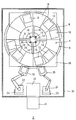
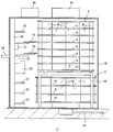
- 1 to 8 show the storage device 2 of the embodiment.
- 4 is a reticle rotating shelf
- 6 is a pod rotating shelf.
- a reticle (not shown) is stored and stored in the inner case 10, and the inner case 10 is lighter than the pod 54 and requires a higher degree of cleanliness.
- the reticle rotating shelf 4 is arranged on the upper part of the pod rotating shelf 6 so as to overlap with each other in plan view, so that the rotating shelves 4 and 6 can rotate independently around the vertical axis.
- the reticle rotating shelf 4 includes a plurality of shelves 9, and each shelf 9 is provided with a plurality of reticle storage chambers 8, which are examples of reticle storage spaces, radially.
- the reticle rotating shelf 4 is rotated by a vertical shaft 12 and a motor 20, and supply pipes 14 and 16 are provided along the shaft 12 to supply N 2 or CDA (Clean Dry Air) to each reticle storage chamber 8.
- Reference numeral 18 denotes a base of the reticle rotating shelf 4.
- the supply pipe 16 extends upward from below along the shaft 12 and supplies clean gas to the supply pipe 14.
- a pod rotation shelf 6 is provided below the reticle rotation shelf 4, and the pod rotation shelf 6 includes a plurality of shelves 41.
- a pod storage chamber 40 which is an example of a pod storage space, is provided on each shelf.
- a plurality are provided radially.
- a pair of elevating platforms 22 and 24 are provided inside the outer wall 30 of the storage device 2, and these elevate and lower along, for example, vertical guides 25 and 26.
- the elevating bodies 22 and 24 include hands 28 and 29, the hand 28 delivers the pod, and the hand 29 delivers the inner case 10.
- the outer wall 30 keeps the inside of the storage device 2 almost airtight with respect to the outside, and 32 is a pod opening / closing device that opens and closes the pod and allows the inner case to be taken in and out.
- Reference numeral 34 denotes a load port, which is provided with a conveyor (not shown) and transfers pods to and from an overhead traveling vehicle or an operator.
- the pod buffer 42 temporarily stores pods.
- the hand 28 delivers the pod among the pod rotating shelf 6, the pod buffer 42, the pod opening / closing device 32, and the load port 34.
- the hand 29 delivers the inner case 10 between the reticle rotating shelf 4 and the pod opening / closing device 32.
- the pod rotating shelf 6 is also provided with a vertical shaft (not shown), and a clean gas supply pipe extends upward from below along the shaft. A clean gas supply pipe extends to each pod storage chamber 40 so as to branch from the supply pipe.
- the reticle since the reticle to be exposed with ultrashort ultraviolet light is stored, the reticle is accommodated in the inner case 10, and each pod 54 accommodates, for example, one inner case 10. However, a plurality of inner cases 10 may be stored in each pod 54. When storing a semiconductor wafer instead of the reticle, the wafer may be stored in the reticle storage chamber 8 in a bare state without using the inner case 10.
- the 44 is an air supply pipe which supplies clean gas such as N2 or CDA to the rotating shelves 4 and 6.
- a pair of filter fan units 45, 46 are provided on the ceiling portion of the storage device 2, and the filter fan unit 45 supplies downflow clean air from the upper part of the reticle rotating shelf 4, thereby surrounding the rotating shelves 4, 6. Keep it clean.
- the filter fan unit 46 supplies downflow clean air toward the pod buffer 42, the hands 28 and 29, the pod opening / closing device 32, and the hands 28 and 29 handle the inner case 10 and the pod 54. Contamination when storing the pod 54 is prevented.
- FIG. 3 shows the supply of clean gas and clean air to the storage device 2.
- the clean gas from the air supply pipe 44 is supplied through the rotary joint 48 shown in FIG. 4 through the vertical shafts of the rotary shelves 4 and 6 through the air supply pipe 16 that extends upward from below to store the reticle.
- the chambers 8 and 10 are individually supplied to the chamber 8 and the pod storage chamber 40.
- the filter fan unit 45 provides a clean air downflow around the rotating shelves 4 and 6, and the filter fan unit 46 provides a clean air downflow around the pod buffer 42 and the like.
- the storage chambers 8 and 40 in the shelves 4 and 6 store articles in clean gas, and wrap the reticle rotating shelf 4 and the pod rotating shelf 6 with a clean air downflow, and in particular the reticle rotating shelf. Clean around 4
- contamination is prevented by clean air.
- FIG. 4 shows a rotary joint 48 provided on the downstream side of the air supply pipe 44.
- one rotary joint 48 is provided for each of the reticle rotary shelf 4 and the pod rotary shelf 6.
- An inner member 50 is rotatably supported by a bearing or the like with respect to the outer member 49, and an air supply pipe 51 is connected to the member 49, communicates with a ventilation path in the member 50, and a plurality of supply pipes are supplied from the ventilation path.
- Air is supplied to branch into the trachea 52.
- the air supply pipe 52 is extended along the shafts of the rotating shelves 4 and 6 to form the air supply pipes 14 and 16 and the like, and are led to the individual storage chambers 8 and 40.
- the structure of the rotary joint 48 is arbitrary.
- FIG. 5 shows a pod 54 stored in the pod storage chamber 40.
- the pod 54 includes, for example, an intake valve 55 and an exhaust valve 56 at the bottom, and accommodates, for example, only one inner case 10 in an airtight manner.
- the pod storage chamber 40 is surrounded by a wall 60 and a door 70 shown in FIG. 7 and the like so as to be substantially airtight.
- the pod storage chamber 40 is supplied with clean gas from an air supply pipe 58 and is supplied from a valve 57 via an intake valve 55 to Supply clean gas inside. Further, the clean gas is exhausted from the exhaust valve 56 to the inside of the storage chamber 40 through the exhaust groove 50.
- the exhaust valve 56 and the groove 59 need not be provided.
- the valve 57 normally closes the tip of the air supply pipe 58 and mechanically opens by contacting the intake valve 55 to supply clean gas.
- the intake valve 55 opens when the external pressure of the pod 54 is higher than the internal pressure and introduces clean gas
- the exhaust valve 56 opens when the internal pressure is higher than the external pressure and exhausts the clean gas from the groove 59.
- exhaust valve 56 is not provided, exhaust is performed so that clean gas leaks from the gap between the pods 54.
- FIG. 6 shows the inner case 10 stored in the reticle storage chamber 8.
- the storage chamber 8 is almost hermetically sealed by a wall 65 and a door described later, and an air supply valve 61 is provided at the tip of the air supply pipe 63. Clean gas is supplied into the storage chamber 8 and discharged into the storage chamber 8 through the exhaust groove 64.
- the valve 61 is opened due to gravity or the like, and clean gas is supplied into the inner case 10.
- FIG. 7 schematically shows a door of the pod storage chamber 40.
- the door 70 is slidable in the vertical direction and is provided with a protrusion 72. Then, the protrusion 72 rises due to a slope provided on the hand 28 and the door 70 opens and closes.
- a similar door is provided in the reticle storage chamber 8.
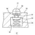
- FIG. 8 shows the structure of the valve 57, and the valve 61 has a similar structure, for example.
- the protrusion 80 protrudes from the floor surface of the pod storage chamber 40 and includes an air supply port 81 and a hole 82 communicating with the air supply port 81.
- a valve body 83 is provided below the protrusion 80, and the elastic body 84 closes the inlet to the flow path 86.
- a gas chamber 85 is connected to a clean gas supply pipe.
- the following effects can be obtained. (1) By protecting the periphery of the reticle rotating shelf 4 and the pod rotating shelf 6 with downflow of clean air and supplying clean gas to each of the storage chambers 8 and 40, articles such as the inner case 10 and the pod 54 Can be stored in an extremely clean state. (2) Since a clean air downflow is supplied to the hands 28, 29 and the pod buffer 42, etc., the pod 54 is stored in the pod buffer 42 when the inner case 10 and the pod 54 are handled by the hands 28, 29, etc. Contamination can be prevented. (3) A door is provided for each storage room 8, 40, the storage room is almost airtight, and a clean gas supply path is provided for each storage room. For this reason, the storage room can be kept clean with a small amount of clean gas.
- a valve 57 or the like is opened by a mechanical mechanism into the reticle storage chamber 8 and the pod storage chamber 6 to supply clean gas. Accordingly, wiring to the shelves 9 and 41 is unnecessary and clean gas can be supplied reliably. Instead of a mechanical valve, an electromagnetic valve or the like may be used to supply clean gas under the control of a controller (not shown). However, if this is done, wiring to the storage chambers 8 and 40 is required. (5) Since one pod 54 or one inner case 10 is stored in one storage chamber, the number of times of opening the door 70 and the like can be minimized, and contamination of articles can be prevented. (6) Clean gas can be supplied even if the storage chambers 6 and 8 are rotated by the rotary joint 48.
Landscapes
- Engineering & Computer Science (AREA)
- Mechanical Engineering (AREA)
- Container, Conveyance, Adherence, Positioning, Of Wafer (AREA)
- Warehouses Or Storage Devices (AREA)
Abstract
Description
・ レチクル用の回転棚とポッド用の回転棚とを設け、レチクル用の回転棚を上に、ポッド用の回転棚を下に重ねる、
・ 昇降自在な2個のハンドと、ポッドオープナー、ポッドを仮置きするバッファ、ポッドを出し入れするロードポートを設け、ポッドとレチクルを受け渡しする、
・ 回転棚内にクリーンエアをダウンフローで吹き込む、
ことを開示している。特許文献2(JP2008-219032A)は、レチクルをインナーケースとアウターケース(ポッド)の2重のケースに収容して取り扱うことを開示している。
前記容器のロードポートと、
前記ロードポートと前記容器保管スペース間で前記容器を搬送する搬送装置と、
各容器保管スペース毎にオン/オフ自在にクリーンガスを供給すると共に、容器に設けられた吸気口に接続自在な配管、とを備えている。
レチクルまたは半導体ウェハーを収納し、かつ吸気口を備えている容器を、前記搬送装置により前記ロードポートと前記容器保管スペース間で搬送するステップと、
前記容器保管スペースに保管されている容器の吸気口に前記配管を接続し、クリーンガスを供給するステップ、とを実行する。
(1) レチクル回転棚4とポッド回転棚6の周囲をクリーンエアのダウンフローで保護し、個々の保管室8,40毎にクリーンガスを供給することにより、インナーケース10及びポッド54等の物品を極めてクリーンな状態で保管できる。
(2) ハンド28,29とポッドバッファ42等に対し、クリーンエアのダウンフローを供給するので、ハンド28,29等でインナーケース10及びポッド54を取り扱う際、及びポッドバッファ42でポッド54を保管する際の汚染を防止できる。
(3) 保管室8,40毎に扉が設けられ、保管室はほぼ気密で、保管室毎にクリーンガスの供給路が設けられている。このため少量のクリーンガスで保管室内を清浄に保つことができる。
(4) レチクル保管室8及びポッド保管室6内へ、メカニカルな機構で弁57等が開いてクリーンガスが供給される。従って棚9,41への配線が不要で、かつ確実にクリーンガスを供給できる。なおメカニカルな弁に代えて電磁弁などを用い、図示しないコントローラの制御によりクリーンガスを供給してもよい。しかしこのようにすると、保管室8,40への配線が必要である。
(5) 1個の保管室に1個のポッド54もしくは1個のインナーケース10を保管するので、扉70等を開く回数を最小にし、物品の汚染を防止できる。
(6) 回転ジョイント48により各保管室6,8が回転しても、クリーンガスを供給できる。
8 レチクル保管室 9,41 棚 10 インナーケース
12 シャフト 14,16 給気管 18 ベース
20 モータ 22,24 昇降体 25,26 ガイド
28,29 ハンド 30 外壁 32 ポッド開閉装置
34 ロードポート 40 ポッド保管室 42 ポッドバッファ
44 給気管 45,46 フィルタファンユニット
48 回転ジョイント 49,50 部材 51,52 給気管
54 ポッド 55 吸気弁 56 排気弁 57 弁
58,63 給気管 59,64 排気溝 60,65 壁
61 給気弁 70 扉 72,80 突起 81 給気口
82 孔 83 弁体 84 弾性体 85 ガス室
86 流路
Claims (6)
- 複数段を備え、かつ各段毎に容器保管スペースを複数備え、鉛直軸回りに回転する回転棚と、
前記容器のロードポートと、
前記ロードポートと前記容器保管スペース間で前記容器を搬送する搬送装置と、
各容器保管スペース毎にオン/オフ自在にクリーンガスを供給すると共に、容器に設けられた吸気口に接続自在な配管、とを備えている保管装置。 - 前記回転棚の上部に平面視で重なるように配置され、かつ前記回転棚とは独立して鉛直軸回りに回転する第2の回転棚で、複数段を備え、かつ各段毎に開閉自在な物品保管スペースを複数備えたものと、
第2の回転棚の上方からクリーンエアをダウンフローで供給するフィルタファンユニットと、
前記容器から前記物品を出し入れする開閉装置と、
前記開閉装置と前記第2の回転棚との間で、物品を搬送する第2の搬送装置と、
各物品保管スペース毎にオン/オフ自在にクリーンガスを供給する第2の配管と、
保管装置の筐体、とをさらに備えていることを特徴とする、請求項1の保管装置。 - 前記容器保管スペースは、容器を搬送する搬送装置のハンドにより開閉自在な扉を備え、
前記物品保管スペースは、物品を搬送する第2の搬送装置のハンドにより開閉自在な扉を備え、
容器に設けられた吸気口に接続自在な配管は容器との接触により流路を開く弁を備え、
前記第2の配管は物品との接触により流路を開く弁を備えていることを特徴とする、請求項2の保管装置。 - 容器に設けられた吸気口に接続自在な配管と前記第2の配管は各々、クリーンガスの供給源側に接続された回転ジョイントと、回転ジョイントから分岐して容器保管スペースあるいは物品保管スペースへクリーンガスを供給する下流側配管とを備えていることを特徴とする、請求項2または3の保管装置。
- 各回転棚は鉛直のシャフトを備え、前記下流側配管は、前記シャフトに沿って下方から上方へ伸びている、請求項4の保管装置。
- 複数段を備え、かつ各段毎に容器保管スペースを複数備え、鉛直軸回りに回転する回転棚と、前記容器のロードポートと、前記ロードポートと前記容器保管スペース間で前記容器を搬送する搬送装置と、各容器保管スペース毎にクリーンガスを供給するための配管とを備えている保管装置を用い、
レチクルまたは半導体ウェハーを収納し、かつ吸気口を備えている容器を、前記搬送装置により前記ロードポートと前記容器保管スペース間で搬送するステップと、
前記容器保管スペースに保管されている容器の吸気口に前記配管を接続し、クリーンガスを供給するステップ、とを実行する保管方法。
Priority Applications (4)
| Application Number | Priority Date | Filing Date | Title |
|---|---|---|---|
| EP12804353.6A EP2727859A4 (en) | 2011-06-28 | 2012-05-17 | MEMORY DEVICE AND STORAGE METHOD |
| US14/125,275 US9296560B2 (en) | 2011-06-28 | 2012-05-17 | Storage device and storage method |
| KR1020147000397A KR20140019028A (ko) | 2011-06-28 | 2012-05-17 | 보관 장치와 보관 방법 |
| JP2013522523A JP5645094B2 (ja) | 2011-06-28 | 2012-05-17 | 保管装置と保管方法 |
Applications Claiming Priority (2)
| Application Number | Priority Date | Filing Date | Title |
|---|---|---|---|
| JP2011142651 | 2011-06-28 | ||
| JP2011-142651 | 2011-06-28 |
Publications (1)
| Publication Number | Publication Date |
|---|---|
| WO2013001930A1 true WO2013001930A1 (ja) | 2013-01-03 |
Family
ID=47423833
Family Applications (1)
| Application Number | Title | Priority Date | Filing Date |
|---|---|---|---|
| PCT/JP2012/062613 Ceased WO2013001930A1 (ja) | 2011-06-28 | 2012-05-17 | 保管装置と保管方法 |
Country Status (6)
| Country | Link |
|---|---|
| US (1) | US9296560B2 (ja) |
| EP (1) | EP2727859A4 (ja) |
| JP (1) | JP5645094B2 (ja) |
| KR (1) | KR20140019028A (ja) |
| TW (1) | TW201307172A (ja) |
| WO (1) | WO2013001930A1 (ja) |
Cited By (3)
| Publication number | Priority date | Publication date | Assignee | Title |
|---|---|---|---|---|
| WO2019102795A1 (ja) * | 2017-11-27 | 2019-05-31 | 村田機械株式会社 | 保管装置 |
| JP2019202872A (ja) * | 2018-05-25 | 2019-11-28 | 西部電機株式会社 | 自動倉庫 |
| JP2021098888A (ja) * | 2019-12-19 | 2021-07-01 | キヤノントッキ株式会社 | マスク収納装置と、これを含む成膜装置 |
Families Citing this family (10)
| Publication number | Priority date | Publication date | Assignee | Title |
|---|---|---|---|---|
| DE102012017786B4 (de) * | 2012-09-10 | 2014-04-17 | Böwe Systec Gmbh | Kartenmassenspeicher, -transport und -speicher sowie Sortierverfahren von Karten |
| JP6414525B2 (ja) * | 2015-09-02 | 2018-10-31 | 株式会社ダイフク | 保管設備 |
| JP7037352B2 (ja) * | 2017-12-26 | 2022-03-16 | 川崎重工業株式会社 | 移送システム |
| KR102102413B1 (ko) * | 2018-09-19 | 2020-04-20 | 크린팩토메이션 주식회사 | 모듈형 용기 스토커 장치 및 그에 사용되는 카로셀 타입의 용기 보관 모듈 |
| KR102202463B1 (ko) | 2019-03-13 | 2021-01-14 | 세메스 주식회사 | 기판 처리 장치 및 방법 |
| USD920020S1 (en) | 2019-11-26 | 2021-05-25 | Applestone Meat Company Llc | Carousel |
| US11191382B2 (en) | 2019-12-26 | 2021-12-07 | Clarence Brent Likins | Revolving cluster mailbox and central package delivery system |
| KR102388390B1 (ko) | 2020-01-06 | 2022-04-21 | 세메스 주식회사 | 로드 포트 유닛, 이를 포함하는 저장 장치 및 배기 방법 |
| TW202232639A (zh) * | 2020-12-18 | 2022-08-16 | 荷蘭商Asm Ip私人控股有限公司 | 具有可旋轉台的晶圓處理設備 |
| TW202534847A (zh) * | 2023-10-25 | 2025-09-01 | 德商布魯克斯自動化(德國)有限公司 | 用於半導體製造物件之存放器及用於操作存放器之方法 |
Citations (4)
| Publication number | Priority date | Publication date | Assignee | Title |
|---|---|---|---|---|
| JPH0529184A (ja) * | 1991-07-19 | 1993-02-05 | Hitachi Ltd | クリーンベンチ |
| JPH11314703A (ja) * | 1998-04-30 | 1999-11-16 | Ebara Corp | 基板保管装置 |
| JP2008219032A (ja) | 2001-08-10 | 2008-09-18 | Asml Holding Nv | レチクルを保護及び搬送する装置及び方法 |
| JP4215079B2 (ja) | 2006-07-31 | 2009-01-28 | 村田機械株式会社 | クリーンストッカと物品の保管方法 |
Family Cites Families (9)
| Publication number | Priority date | Publication date | Assignee | Title |
|---|---|---|---|---|
| US4418646A (en) * | 1982-03-29 | 1983-12-06 | Eaton Corporation | Load lock valve |
| KR0163400B1 (ko) | 1996-07-31 | 1998-12-01 | 송오식 | 전조등 자동제어기 |
| US6875282B2 (en) | 2001-05-17 | 2005-04-05 | Ebara Corporation | Substrate transport container |
| DE10350517A1 (de) * | 2003-10-29 | 2005-06-09 | Sieghard Schiller Gmbh & Co. Kg | Wafer-Stocker |
| JP2005167168A (ja) | 2003-12-02 | 2005-06-23 | Dan-Takuma Technologies Inc | パージバルブおよび保管装置 |
| JP2007227800A (ja) | 2006-02-24 | 2007-09-06 | Hitachi Kokusai Electric Inc | 基板保管輸送容器及び基板保管輸送容器パージシステム |
| FR2902235B1 (fr) * | 2006-06-09 | 2008-10-31 | Alcatel Sa | Dispositif de transport, de stockage et de transfert de substrats |
| KR100901495B1 (ko) * | 2007-10-11 | 2009-06-08 | 세메스 주식회사 | 기판 처리 장치 및 그 세정 방법 |
| JP4692584B2 (ja) * | 2008-07-03 | 2011-06-01 | 村田機械株式会社 | パージ装置 |
-
2012
- 2012-05-17 JP JP2013522523A patent/JP5645094B2/ja active Active
- 2012-05-17 WO PCT/JP2012/062613 patent/WO2013001930A1/ja not_active Ceased
- 2012-05-17 US US14/125,275 patent/US9296560B2/en active Active
- 2012-05-17 KR KR1020147000397A patent/KR20140019028A/ko not_active Ceased
- 2012-05-17 EP EP12804353.6A patent/EP2727859A4/en not_active Withdrawn
- 2012-06-21 TW TW101122198A patent/TW201307172A/zh unknown
Patent Citations (4)
| Publication number | Priority date | Publication date | Assignee | Title |
|---|---|---|---|---|
| JPH0529184A (ja) * | 1991-07-19 | 1993-02-05 | Hitachi Ltd | クリーンベンチ |
| JPH11314703A (ja) * | 1998-04-30 | 1999-11-16 | Ebara Corp | 基板保管装置 |
| JP2008219032A (ja) | 2001-08-10 | 2008-09-18 | Asml Holding Nv | レチクルを保護及び搬送する装置及び方法 |
| JP4215079B2 (ja) | 2006-07-31 | 2009-01-28 | 村田機械株式会社 | クリーンストッカと物品の保管方法 |
Non-Patent Citations (1)
| Title |
|---|
| See also references of EP2727859A4 |
Cited By (10)
| Publication number | Priority date | Publication date | Assignee | Title |
|---|---|---|---|---|
| WO2019102795A1 (ja) * | 2017-11-27 | 2019-05-31 | 村田機械株式会社 | 保管装置 |
| CN111372873A (zh) * | 2017-11-27 | 2020-07-03 | 村田机械株式会社 | 保管装置 |
| JPWO2019102795A1 (ja) * | 2017-11-27 | 2020-11-19 | 村田機械株式会社 | 保管装置 |
| CN111372873B (zh) * | 2017-11-27 | 2021-05-25 | 村田机械株式会社 | 保管装置 |
| US11533991B2 (en) | 2017-11-27 | 2022-12-27 | Murata Machinery, Ltd. | Storage apparatus |
| JP2019202872A (ja) * | 2018-05-25 | 2019-11-28 | 西部電機株式会社 | 自動倉庫 |
| JP7058557B2 (ja) | 2018-05-25 | 2022-04-22 | 西部電機株式会社 | 自動倉庫 |
| JP2021098888A (ja) * | 2019-12-19 | 2021-07-01 | キヤノントッキ株式会社 | マスク収納装置と、これを含む成膜装置 |
| JP7058316B2 (ja) | 2019-12-19 | 2022-04-21 | キヤノントッキ株式会社 | マスク収納装置と、これを含む成膜装置 |
| TWI824208B (zh) * | 2019-12-19 | 2023-12-01 | 日商佳能特機股份有限公司 | 遮罩收納裝置及包含其之成膜裝置 |
Also Published As
| Publication number | Publication date |
|---|---|
| US9296560B2 (en) | 2016-03-29 |
| TW201307172A (zh) | 2013-02-16 |
| EP2727859A1 (en) | 2014-05-07 |
| US20140124331A1 (en) | 2014-05-08 |
| JP5645094B2 (ja) | 2014-12-24 |
| KR20140019028A (ko) | 2014-02-13 |
| EP2727859A4 (en) | 2015-01-21 |
| JPWO2013001930A1 (ja) | 2015-02-23 |
Similar Documents
| Publication | Publication Date | Title |
|---|---|---|
| JP5645094B2 (ja) | 保管装置と保管方法 | |
| JP7372362B2 (ja) | 半導体システムにおける湿度制御 | |
| JP7480249B2 (ja) | 基板処理装置 | |
| JP4027837B2 (ja) | パージ装置およびパージ方法 | |
| TWI788422B (zh) | Efem及efem之氣體置換方法 | |
| JP6430870B2 (ja) | クランプ装置及びこれを用いた基板搬入出装置、並びに基板処理装置 | |
| TWI868516B (zh) | 搬送系統,容器開閉裝置 | |
| CN102820247B (zh) | 基板输送容器的开闭装置、盖体的开闭装置及半导体制造装置 | |
| WO2007149513A4 (en) | System for purging reticle storage | |
| JP2009541998A5 (ja) | ||
| KR20080012116A (ko) | 클린 스토커와 물품의 보관방법 | |
| JP5854136B2 (ja) | 蓋開閉装置 | |
| TWI829832B (zh) | 物品保管設備 | |
| JPWO2007114293A1 (ja) | ウエハー用保管庫及びその保管制御方法 | |
| JP4120285B2 (ja) | 被処理体の導入ポート機構及びこれを用いた処理システム | |
| JP6972110B2 (ja) | 基板処理装置 | |
| CN1307706C (zh) | 半导体处理装置中的端口结构 | |
| JP2011159834A (ja) | ガス置換装置を備えた基板搬送装置、基板搬送システム、置換方法 | |
| JP2012169534A (ja) | 基板処理装置及び半導体装置の製造方法 | |
| TWI722176B (zh) | 裝載埠及晶圓的搬送方法 | |
| TW201701393A (zh) | 載體搬送裝置及載體搬送方法 | |
| JP2014110299A (ja) | 蓋開閉装置 | |
| JP2014060338A (ja) | 基板処理装置 | |
| JP4906824B2 (ja) | 液処理装置 | |
| JPH04184927A (ja) | ウエハのクリーニングシステム |
Legal Events
| Date | Code | Title | Description |
|---|---|---|---|
| 121 | Ep: the epo has been informed by wipo that ep was designated in this application |
Ref document number: 12804353 Country of ref document: EP Kind code of ref document: A1 |
|
| DPE1 | Request for preliminary examination filed after expiration of 19th month from priority date (pct application filed from 20040101) | ||
| WWE | Wipo information: entry into national phase |
Ref document number: 2012804353 Country of ref document: EP |
|
| ENP | Entry into the national phase |
Ref document number: 2013522523 Country of ref document: JP Kind code of ref document: A |
|
| WWE | Wipo information: entry into national phase |
Ref document number: 14125275 Country of ref document: US |
|
| NENP | Non-entry into the national phase |
Ref country code: DE |
|
| ENP | Entry into the national phase |
Ref document number: 20147000397 Country of ref document: KR Kind code of ref document: A |