WO2013002003A1 - コンデンサ - Google Patents
コンデンサ Download PDFInfo
- Publication number
- WO2013002003A1 WO2013002003A1 PCT/JP2012/064652 JP2012064652W WO2013002003A1 WO 2013002003 A1 WO2013002003 A1 WO 2013002003A1 JP 2012064652 W JP2012064652 W JP 2012064652W WO 2013002003 A1 WO2013002003 A1 WO 2013002003A1
- Authority
- WO
- WIPO (PCT)
- Prior art keywords
- capacitor
- electrode plate
- block
- bypass
- terminal
- Prior art date
- Legal status (The legal status is an assumption and is not a legal conclusion. Google has not performed a legal analysis and makes no representation as to the accuracy of the status listed.)
- Ceased
Links
Images





Classifications
-
- H—ELECTRICITY
- H01—ELECTRIC ELEMENTS
- H01G—CAPACITORS; CAPACITORS, RECTIFIERS, DETECTORS, SWITCHING DEVICES, LIGHT-SENSITIVE OR TEMPERATURE-SENSITIVE DEVICES OF THE ELECTROLYTIC TYPE
- H01G4/00—Fixed capacitors; Processes of their manufacture
- H01G4/38—Multiple capacitors, i.e. structural combinations of fixed capacitors
- H01G4/385—Single unit multiple capacitors, e.g. dual capacitor in one coil
-
- H—ELECTRICITY
- H01—ELECTRIC ELEMENTS
- H01G—CAPACITORS; CAPACITORS, RECTIFIERS, DETECTORS, SWITCHING DEVICES, LIGHT-SENSITIVE OR TEMPERATURE-SENSITIVE DEVICES OF THE ELECTROLYTIC TYPE
- H01G4/00—Fixed capacitors; Processes of their manufacture
- H01G4/002—Details
- H01G4/228—Terminals
-
- H—ELECTRICITY
- H01—ELECTRIC ELEMENTS
- H01G—CAPACITORS; CAPACITORS, RECTIFIERS, DETECTORS, SWITCHING DEVICES, LIGHT-SENSITIVE OR TEMPERATURE-SENSITIVE DEVICES OF THE ELECTROLYTIC TYPE
- H01G4/00—Fixed capacitors; Processes of their manufacture
- H01G4/002—Details
- H01G4/228—Terminals
- H01G4/232—Terminals electrically connecting two or more layers of a stacked or rolled capacitor
-
- H—ELECTRICITY
- H01—ELECTRIC ELEMENTS
- H01G—CAPACITORS; CAPACITORS, RECTIFIERS, DETECTORS, SWITCHING DEVICES, LIGHT-SENSITIVE OR TEMPERATURE-SENSITIVE DEVICES OF THE ELECTROLYTIC TYPE
- H01G4/00—Fixed capacitors; Processes of their manufacture
- H01G4/002—Details
- H01G4/228—Terminals
- H01G4/248—Terminals the terminals embracing or surrounding the capacitive element, e.g. caps
-
- H—ELECTRICITY
- H01—ELECTRIC ELEMENTS
- H01G—CAPACITORS; CAPACITORS, RECTIFIERS, DETECTORS, SWITCHING DEVICES, LIGHT-SENSITIVE OR TEMPERATURE-SENSITIVE DEVICES OF THE ELECTROLYTIC TYPE
- H01G4/00—Fixed capacitors; Processes of their manufacture
- H01G4/38—Multiple capacitors, i.e. structural combinations of fixed capacitors
-
- H—ELECTRICITY
- H01—ELECTRIC ELEMENTS
- H01G—CAPACITORS; CAPACITORS, RECTIFIERS, DETECTORS, SWITCHING DEVICES, LIGHT-SENSITIVE OR TEMPERATURE-SENSITIVE DEVICES OF THE ELECTROLYTIC TYPE
- H01G2/00—Details of capacitors not covered by a single one of groups H01G4/00-H01G11/00
- H01G2/08—Cooling arrangements; Heating arrangements; Ventilating arrangements
Definitions
- the present invention relates to a capacitor using a capacitor block configured by electrically connecting a plurality of capacitor elements in parallel.
- a large-capacity capacitor exceeding 100 ⁇ F when a large-capacity capacitor exceeding 100 ⁇ F is configured, a plurality of capacitor elements of less than 100 ⁇ F or around 100 ⁇ F are prepared in order to obtain a required capacitance, and these capacitor elements are made of flat knitted copper wire.
- a plurality of capacitor blocks may be connected in parallel for use.
- a ripple current such as the carrier frequency of the inverter flows through the capacitor.
- self-heating is generated from the capacitor element and the wiring material, resulting in a decrease in life. Therefore, conventionally, a parallel plate is used as a wiring material for connecting a plurality of capacitor elements in parallel to reduce self-inductance, thereby improving high-frequency characteristics and reducing self-heating (Japanese Patent No. 37771977). And Japanese Patent No. 3357314).
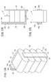
- Japanese Patent No. 3357314 attention is also paid to the current flowing through the capacitor element, and the side surface of the capacitor block (capacitor block in which a plurality of capacitor elements are assembled in 5 rows and 2 columns) is surrounded as a parallel plate in the opposite direction. It has a wiring structure.
- the wiring structure described above has an integrated box structure, which makes it difficult to assemble as a capacitor. That is, in the structure shown in Japanese Patent No. 3357314, as shown in FIG. 2 (e), the connection plates 6a on both sides surrounding the side surface of the capacitor block are integrated with the drawer plate 6b.
- connection plate 4a when assembling as a capacitor, the connection plate 4a is connected to one terminal portion of the capacitor block, the connection plate 4b is connected to the other terminal portion, and then the lead plate 5 is connected to the connection plate 4a. Thereafter, the capacitor block must be inserted into the space surrounded by the two connection plates 6a and the one extraction plate 6b, and each end of the two connection plates 6a must be connected to the connection plate 4b.
- the present invention has been made in consideration of such problems, and it is not necessary to prepare a dedicated wiring structure, can flexibly cope with specification changes and the like, and can reduce costs. It is an object to provide a capacitor that can reduce self-inductance.
- a capacitor according to the present invention is a capacitor using a capacitor block configured by electrically connecting a plurality of capacitor elements each having terminal portions at both ends in parallel, and each terminal of the plurality of capacitor elements
- a first electrode plate that electrically connects parts
- a second electrode plate that electrically connects each of the other terminal parts of the plurality of capacitor elements and is led out to the one terminal part side
- One or more bypass electrode plates that electrically bypass the second electrode plate, and the second electrode plate includes a connection portion that electrically connects each of the other terminal portions of the plurality of capacitor elements;
- the lead-out portion disposed opposite to the first electrode plate and the connection portion connecting the connection portion and the lead-out portion are integrally formed, and the bypass electrode plate is the lead-out portion of the second electrode plate.
- connection part A connection part Part electrically connected to the part A connection part, a second connection part electrically connected to the connection part of the second electrode plate, and a third connection part for connecting the first connection part and the second connection part are integrally provided.
- the connection portion of the second electrode plate is positioned below the lower surface of the capacitor block, and the third connection portion of the bypass electrode plate is disposed at a position facing the side surface of the capacitor block. It is characterized by being.
- the present invention is characterized in that at least two bypass electrode plates are arranged to face each other with the capacitor block interposed therebetween.
- the present invention is characterized in that at least two bypass electrode plates are arranged along one side surface of the capacitor block.
- At least one of the bypass electrode plates is arranged so that an upper end position thereof substantially coincides with an upper surface of the capacitor block.
- the capacitor block is configured by stacking the plurality of capacitor elements in one direction, and the length of the bypass electrode plate along the stacking direction of the plurality of capacitor elements is L, the capacitor When the number of the capacitor elements constituting the block is N and the length of the one capacitor element along the stacking direction is m, the length L is: m ⁇ L ⁇ m ⁇ N It is characterized by being.
- the length L is m ⁇ (N ⁇ 1) ⁇ L ⁇ m ⁇ N It is characterized by being.
- the length L of at least one of the bypass electrode plates is: m ⁇ L ⁇ 2 ⁇ m It is characterized by being.
- the present invention is characterized in that it has a composite capacitor block in which two or more capacitor blocks are arranged with their side surfaces facing each other.
- a cooling member that cools at least one of each of the one terminal portion and each of the other terminal portions of the capacitor block is provided, and the cooling member includes each of the one of the capacitor blocks. Is provided so as to face at least one of a portion where the terminal portions are arranged and a portion where the other terminal portions of the capacitor block are arranged.
- the capacitor of the present invention it is not necessary to prepare a dedicated wiring structure, it is possible to flexibly cope with specification changes, etc., it is possible to reduce the cost, and the self-inductance is also reduced. Can be planned.
- the capacitor Normally, if a current exceeding the allowable value flows, the capacitor will exceed the allowable temperature of the capacitor over time, and there is a risk that it will eventually smoke or ignite. However, since the cooling member is provided, even if a current exceeding the allowable value flows, the allowable temperature of the capacitor is not exceeded, and the occurrence of the above-described problems can be avoided.
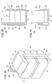
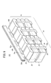
- FIG. 1A is a perspective view showing a capacitor (first capacitor) according to a first embodiment
- FIG. 1B is a side view showing a partially broken bypass electrode plate of the first capacitor
- FIG. It is a top view which shows 1 capacitor
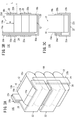
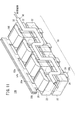
- 2A is a perspective view showing a capacitor (second capacitor) according to the second embodiment
- FIG. 2B is a side view showing a partially broken bypass electrode plate of the second capacitor
- FIG. 3A is a perspective view showing a capacitor (third capacitor) according to the third embodiment
- FIG. 3B is a side view showing a partially broken bypass electrode plate of the third capacitor
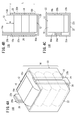
- FIG. 4A is a perspective view showing a capacitor (fourth capacitor) according to a fourth embodiment
- FIG. 4B is a side view showing a partially broken bypass electrode plate of the fourth capacitor
- FIG. It is a top view which shows 4 capacitors seeing from an upper surface
- FIG. 5A is a perspective view showing a capacitor (fifth capacitor) according to a fifth embodiment
- FIG. 5B is a side view showing a partially broken bypass electrode plate of the fifth capacitor
- 6A is a perspective view showing a capacitor (sixth capacitor) according to a sixth embodiment
- 6B is a side view showing a partially broken bypass electrode plate of the sixth capacitor, and FIG. It is a top view which shows 6 capacitors seeing from an upper surface. It is a perspective view which shows the capacitor
- FIG. 12A is a perspective view showing a capacitor according to the comparative example
- FIG. 12B is a side view showing a partially broken bypass electrode plate of the capacitor according to the comparative example
- FIG. 12C shows the capacitor according to the comparative example from above.
- FIG. It is explanatory drawing which shows the method of measuring the inductance of a capacitor
- the capacitor according to the first embodiment (hereinafter referred to as the first capacitor 10A) has one capacitor block 14 including a plurality of capacitor elements 12, as shown in FIG. 1A.
- the capacitor block 14 is configured by laminating a plurality of capacitor elements 12 in one direction.
- FIG. 1 shows an example in which one capacitor block 14 is configured by stacking four capacitor elements 12 in the vertical direction.
- Each capacitor element 12 is electrically connected to the wound body 16, the first terminal portion 18 a electrically connected to one end of the wound body 16, and the other end of the wound body 16.
- Second terminal portion 18b the wound body 16 has a configuration in which the first electrode pattern and the second electrode pattern are wound in a state of facing each other with the dielectric film interposed therebetween.
- the wound body 16 includes a first dielectric film in which a first electrode pattern is formed on one side and a second dielectric film in which a second electrode pattern is formed on one side. The first dielectric film and the second dielectric film are overlapped so as not to come into contact with the pattern, and the superimposed first dielectric film and second dielectric film are wound.
- the first dielectric film and the second dielectric film can be composed of PP (polypropylene), PET (polyethylene terephthalate), PPS (polyphenylene sulfide), and the like, respectively.
- the first terminal portion 18a and the second terminal portion 18b are provided on one end surface and the other end surface of the wound body 16 by thermally spraying a metal such as solder or zinc.
- the first capacitor 10A includes a first electrode plate 20a that electrically connects the first terminal portions 18a of the plurality of capacitor elements 12, and a second electrode of each of the plurality of capacitor elements 12.
- the terminal portion 18b is electrically connected, and has a second electrode plate 20b led out to the first terminal portion 18a side. That is, the first capacitor 10A has a configuration in which a plurality of capacitor elements 12 are electrically connected in parallel by the first electrode plate 20a and the second electrode plate 20b.
- the first capacitor 10A has one bypass electrode plate 22 that electrically bypasses the second electrode plate 20b.
- the second electrode plate 20 b is connected to the connection portion 24 that electrically connects the second terminal portions 18 b of the plurality of capacitor elements 12 and the first terminal portion 18 a side of the plurality of capacitor elements 12.
- the lead-out part 26 led out and arranged opposite to the first electrode plate 20a and the connection part 28 connecting the connection part 24 and the lead-out part 26 are integrally provided.
- the connection portion 28 of the second electrode plate 20 b is located below the lower surface of the capacitor block 14. That is, the second electrode plate 20b has a longer wiring length than the first electrode plate 20a.
- condenser element 12 capacitor element 12 located in the lowest
- an insulating plate (not shown) is interposed in each.
- the bypass electrode plate 22 has a first connection portion 22a electrically connected to the lead-out portion 26 of the second electrode plate 20b and a second connection electrically connected to the connection portion 24 of the second electrode plate 20b.
- the unit 22b and the third connection part 22c for connecting the first connection part 22a and the second connection part 22b are integrally provided.
- the third connection portion 22 c of the bypass electrode plate 22 is disposed at a position facing one side surface of the capacitor block 14. That is, the bypass electrode plate 22 is electrically connected to the second electrode plate 20 b so as to surround one side surface of the capacitor block 14.
- the first connection portion 22a, the second connection portion 22b, and the third connection portion 22c are integrally provided by forming a rectangular metal plate into a U-shaped cross section by, for example, bending. I have to.
- the electrical connection between the first connection portion 22a and the lead-out portion 26 of the second electrode plate 20b, and the electrical connection between the second connection portion 22b and the connection portion 24 of the second electrode plate 20b are performed by, for example, soldering.
- the third connection portion 22 c of the bypass electrode plate 22 is preferably separated from one side surface of the capacitor block 14. In this case, an electrical insulating material may be interposed between the third connection portion 22 c and one side surface of the capacitor block 14.
- the length along the stacking direction of the plurality of capacitor elements 12 of the bypass electrode plate 22 is L
- the number of capacitor elements 12 constituting the capacitor block 14 is N
- the length along the stacking direction of one capacitor element 12 is m
- the length L is m ⁇ L ⁇ m ⁇ N
- the length L is m ⁇ (N ⁇ 1) ⁇ L ⁇ m ⁇ N Is satisfied.
- the first capacitor 10A a plurality of capacitor elements 12 are connected in parallel by the first electrode plate 20a and the second electrode plate 20b, and the wiring length is longer than that of the first electrode plate 20a. Since one bypass electrode plate 22 that electrically bypasses the two-electrode plate 20b is electrically connected to the second electrode plate 20b, the self-inductance of the first capacitor 10A can be reduced, and high-frequency characteristics can be reduced. Improvement and reduction of self-heating can be achieved. In addition, since it is only necessary to electrically connect the bypass electrode plate 22 to the second electrode plate 20b having a long wiring length, the assembly is simple, there is no need to prepare a dedicated wiring structure (box structure), and the specification is changed. Etc. can be flexibly dealt with. This leads to an improvement in the productivity of the first capacitor 10A and a reduction in cost.
- FIG. 1 shows the case where four capacitor elements 12 are laminated, other two capacitor elements 12, three capacitor elements 12, and five or more capacitor elements 12 are laminated. Of course, it can also be applied to cases.
- the capacitor according to the second embodiment (hereinafter referred to as the second capacitor 10B) has substantially the same configuration as the first capacitor 10A described above, as shown in FIGS. 2A to 2C.
- the point where two bypass electrode plates 22 are arranged along one side surface of the capacitor block 14 and the above-described length L of the bypass electrode plate 22 are as follows. m ⁇ L ⁇ 2 ⁇ m It is different in that.
- This field also has the same effect as the effect of the first capacitor 10A described above.
- 2A to 2C show the case where four capacitor elements 12 are stacked, it is needless to say that the present invention can be applied to a case where five or more capacitor elements 12 are stacked.
- the length L described above as the bypass electrode plate 22 is m ⁇ L ⁇ 2 ⁇ .
- the bypass electrode plate 22 which is m it is preferable to use the bypass electrode plate 22 whose length L described above is 2 ⁇ m ⁇ L ⁇ 3 ⁇ m. That is, when two or more bypass electrode plates 22 are arranged in the stacking direction with respect to one capacitor block 14, the above-described length L is m ⁇ L ⁇ 2 ⁇ m, If the bypass electrode plate 22 satisfying xm ⁇ L ⁇ 3 ⁇ m is prepared, it can be applied to various capacitor blocks in which four or more capacitor elements 12 are laminated.
- a capacitor according to the third embodiment (hereinafter referred to as a third capacitor 10C) has substantially the same configuration as the second capacitor 10B described above, as shown in FIGS. 3A to 3C.
- the difference is that the bypass electrode plate 22 installed in the upper part in the direction is arranged so that the position of the upper end 22d thereof and the upper surface 14a of the capacitor block 14 are substantially coincident with each other.
- the third capacitor 10C has the same effect as the second capacitor 10B described above.
- the third capacitor 10C is installed so that the bypass electrode plate 22 installed at the upper part in the stacking direction approaches the end of the second electrode plate 20b (the end connected to the external terminal).
- the self-inductance can be reduced as compared with the second capacitor 10B.
- a capacitor according to the fourth embodiment (hereinafter referred to as a fourth capacitor 10D) has substantially the same configuration as the first capacitor 10A described above, as shown in FIGS. 4A to 4C. The difference is that two bypass electrode plates 22 are provided, and that these two bypass electrode plates 22 are arranged opposite to each other with the capacitor block 14 interposed therebetween.
- the self-inductance is reduced to the first capacitor. It can be about 1 ⁇ 2 of the self-inductance of 10A.
- the capacitor according to the fifth embodiment (hereinafter referred to as the fifth capacitor 10E) is substantially the same as the above-described second capacitor 10B (see FIGS. 2A to 2C), as shown in FIGS. 5A to 5C.
- the fifth capacitor 10E is substantially the same as the above-described second capacitor 10B (see FIGS. 2A to 2C), as shown in FIGS. 5A to 5C.
- two bypass electrode plates 22 are arranged opposite to each other with the capacitor block 14 in between, in the point of having four bypass electrode plates 22 and the upper part of the capacitor block 14 in the stacking direction.
- two bypass electrode plates 22 are different from each other in that they are arranged to face each other with the capacitor block 14 interposed therebetween.
- the inductance can be about 1 ⁇ 2 of the self-inductance of the second capacitor 10B.
- the capacitor according to the sixth embodiment (hereinafter referred to as the sixth capacitor 10F) is substantially the same as the above-described third capacitor 10C (see FIGS. 3A to 3C), as shown in FIGS. 6A to 6C.
- the sixth capacitor 10F has the same configuration, two bypass electrode plates 22 are arranged opposite to each other with the capacitor block 14 in between, in the point of having four bypass electrode plates 22 and the upper part of the capacitor block 14 in the stacking direction.
- two bypass electrode plates 22 are different from each other in that they are arranged to face each other with the capacitor block 14 interposed therebetween.
- the self-inductance is reduced by the third capacitor 10C. It can be about 1 ⁇ 2 of the self-inductance.
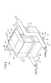
- the capacitor according to the seventh embodiment (hereinafter referred to as a seventh capacitor 10G) has a configuration substantially similar to that of the fifth capacitor 10E (see FIGS. 5A to 5C) described above, as shown in FIG. However, it is different in that a cooling member 30 for cooling at least the second terminal portion 18b of each capacitor element 12 is provided.
- the cooling member 30 is composed of, for example, a pipe 32 through which a cooling medium (cooling water, cooling air, etc.) flows, and is installed at a position facing the portion where the second terminal portions 18b are arranged. Since the pipe 32 is installed in contact with the second connection portion 22b of the bypass electrode plate 22, the heat generated in the second terminal portion 18b is the second connection between the second electrode plate 20b and the bypass electrode plate 22.
- the heat radiated to the cooling member 30 through the portion 22b and generated in the first terminal portion 18a is generated by the first electrode plate 20a, the electrical insulating material, the first connection portion 22a of the bypass electrode plate 22, and the third connection portion. Heat is radiated to the cooling member 30 via the 22c and the second connecting portion 22b.
- the capacitor will exceed the allowable temperature of the capacitor over time, and there is a risk that it will eventually smoke or ignite.
- the cooling member 30 is provided in the seventh capacitor 10G, the allowable temperature of the seventh capacitor 10G does not exceed the allowable temperature even when a current exceeding the allowable value flows. Can be avoided.
- a heat sink in addition to the pipe 32 through which the above-described cooling medium flows, a heat sink can also be used.
- the pipe 32 and the heat sink may be combined.
- the capacitor according to the eighth embodiment (hereinafter referred to as the eighth capacitor 10H) has substantially the same configuration as the seventh capacitor 10G described above, as shown in FIG.
- the 2nd cooling member 34 differs in the point installed in the position facing the site
- the second cooling member 34 similarly to the cooling member 30, a pipe 32 through which a cooling medium flows, a heat sink, or the like can be used.
- the heat generated in the 1st terminal part 18a is the 1st electrode plate 20a, the electricity The heat is dissipated to the second cooling member 34 via the first connecting portion 22 a of the mechanical insulating material and the bypass electrode plate 22. That is, the heat generated in the first terminal portion 18a can be efficiently radiated to the second cooling member 34.
- a capacitor according to a ninth embodiment (hereinafter referred to as a ninth capacitor 10I) will be described with reference to FIG.
- the ninth capacitor 10I has a composite capacitor block 50 formed by arranging a plurality of capacitor blocks 14 with their side surfaces facing each other.
- four second capacitors 10B are arranged in the horizontal direction (direction perpendicular to the stacking direction of the capacitor elements 12), and the side surfaces of the adjacent second capacitors 10B are opposed to each other.
- the arranged form is shown.
- the end of the first electrode plate 20a of each second capacitor 10B is connected to a common first lead terminal plate 52a, and the end of the second electrode plate 20b of each second capacitor 10B is connected to a common second lead terminal. It is connected to the plate 52b.
- bypass paths in this case, four bypass paths
- the self-inductance can be about 1 ⁇ 4 of the self-inductance of the second capacitor 10B.
- a capacitor according to a tenth embodiment (hereinafter referred to as a tenth capacitor 10J) is a composite in which a plurality of capacitor blocks 14 are arranged with their side surfaces facing each other, as shown in FIG.
- the capacitor block 50 is provided, and in particular, the four fifth capacitors 10E are arranged in the lateral direction (direction orthogonal to the stacking direction of the capacitor elements 12), and the side surfaces of the adjacent fifth capacitors 10E are opposed to each other. It has an arranged form.
- the end of the first electrode plate 20a of each fifth capacitor 10E is connected to a common first lead terminal plate 52a, and the end of the second electrode plate 20b of each fifth capacitor 10E is connected to a common second lead terminal. It is connected to the plate 52b.
- bypass paths in this case, eight bypass paths
- the self-inductance can be about 1 ⁇ 4 of the self-inductance of the fifth capacitor 10E.
- the capacitor according to the eleventh embodiment (hereinafter referred to as the eleventh capacitor 10K) has substantially the same configuration as the tenth capacitor 10J described above, as shown in FIG. Is different in that a cooling member 30 for cooling at least the second terminal portion 18b is provided.
- the cooling member 30 is composed of, for example, a meandering pipe 32 through which a cooling medium (cooling water, cooling air, etc.) flows, and is installed at a position facing the portion where the second terminal portions 18b are arranged.
- the eleventh capacitor 10K similarly to the above-described seventh capacitor 10G (see FIG. 7), even if a current exceeding the allowable value flows in each capacitor, the allowable temperature of each capacitor is not exceeded. The occurrence of the above-described problems can be avoided.
- the second cooling member 34 may be installed at a position facing the portion where the first terminal portions 18a are arranged.
- the inductance of the capacitor was measured using a network analyzer.
- the configuration of the capacitor according to the comparative example and Examples 1 to 8 is as follows.
- the first embodiment has the same configuration as the first capacitor 10A shown in FIGS. 1A to 1C
- the second embodiment has the same configuration as the second capacitor 10B shown in FIGS. 2A to 2C
- 3 has the same configuration as the third capacitor 10C shown in FIGS. 3A to 3C
- the fourth embodiment has the same configuration as the fourth capacitor 10D shown in FIGS. 4A to 4C
- 5A to 5C have the same configuration as the fifth capacitor 10E
- the sixth embodiment has the same configuration as the sixth capacitor 10F shown in FIGS. 6A to 6C.
- Example 7 has the same configuration as the ninth capacitor 10I shown in FIG. 9, and Example 8 has the same configuration as the tenth capacitor 10J shown in FIG.
- a network analyzer 60 was used as shown in FIG. Specifically, in each capacitor according to the comparative example and Examples 1 to 8, the end portion of the first electrode plate 20a (first lead terminal plate 52a in the seventh and eighth embodiments) and the second electrode plate 20b (the second lead terminal plate 52b in the seventh and eighth embodiments) (specifically, each external terminal of the capacitor) is connected to the connector portions of the inner core wires 64a and 64b in the coaxial cables 62a and 62b, respectively. And the connector portions of the outer conductors 66a and 66b were connected (possibly reversed) and measured.
- the measurement frequency is 100 Hz to 200 Hz
- the measurement current is several mA
- the measurement voltage is several mV.
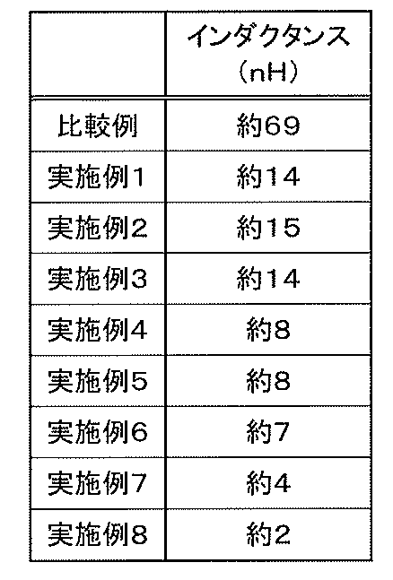
- the inductance was about 69 nH in the comparative example, but all of Examples 1 to 8 were 15 nH or less, and the inductance could be reduced as compared with the comparative example. It can be seen that this can be reduced.
- the fourth embodiment has a configuration in which two bypass paths by the bypass electrode plate 22 are connected in parallel to the configuration of the first embodiment (see FIG. 1A). It is about 1 ⁇ 2 of the inductance of Example 1.
- Example 5 since the two bypass paths by the bypass electrode plate 22 are connected in parallel to the configuration of Example 2 (see FIG. 2A), the inductance is This is about 1 ⁇ 2 of the inductance of the second embodiment.
- Example 6 as well, as shown in FIG. 6A, since the two bypass paths by the bypass electrode plate 22 are connected in parallel to the configuration of Example 3 (see FIG. 3A), the inductance is This is about 1 ⁇ 2 of the inductance of the third embodiment.
- bypass paths in this case, four bypass paths
- the inductance is about 1 ⁇ 4 of the inductance of the second capacitor 10B.
- bypass paths in this case, four bypass paths
- the inductance is about 1 ⁇ 4 of the inductance of the fifth capacitor 10E.
- the inductance of the capacitor described in Japanese Patent No. 3357314 is about 1 ⁇ 4 of the comparative example, that is, about 17 nH, which is higher than the inductances of Examples 1 to 8.
- the capacitor according to the present invention is not limited to the above-described embodiment, and various configurations can be adopted without departing from the gist of the present invention.
Landscapes
- Engineering & Computer Science (AREA)
- Power Engineering (AREA)
- Manufacturing & Machinery (AREA)
- Microelectronics & Electronic Packaging (AREA)
- Fixed Capacitors And Capacitor Manufacturing Machines (AREA)
Abstract
Description
m<L<m×N
であることを特徴とする。
m×(N-1)<L<m×N
であることを特徴とする。
m<L<2×m
であることを特徴とする。
m<L<m×N
の範囲であり、特に、この第1コンデンサ10Aでは、長さLは、
m×(N-1)<L<m×N
を満足している。
m<L<2×m
である点で異なる。この場も、上述した第1コンデンサ10Aの効果と同様の効果を奏する。なお、図2A~図2Cの例では、4個のコンデンサ素子12を積層した場合を示しているが、その他、5個以上のコンデンサ素子12を積層した場合にも適用できることはもちろんである。特に、5個、7個、9個等のように、5以上の奇数個のコンデンサ素子12を積層した場合には、バイパス電極板22として、上述した長さLが、m<L<2×mであるバイパス電極板22に加えて、上述した長さLが、2×m<L<3×mであるバイパス電極板22を用いることが好ましい。つまり、1つのコンデンサブロック14に対して積層方向に2個以上のバイパス電極板22を配列する場合は、上述した長さLが、m<L<2×mであるバイパス電極板22と、2×m<L<3×mであるバイパス電極板22とを用意しておけば、4個以上のコンデンサ素子12が積層された種々のコンデンサブロックに適用させることができる。
図12A~図12Cに示すように、図1A~図1Cに示す第1コンデンサ10Aからバイパス電極板22を外した構成を有する。この構成は、上述した特許第3771977号公報に記載のコンデンサに類似した構造である。
実施例1は、図1A~図1Cに示す第1コンデンサ10Aと同様の構成を有し、実施例2は、図2A~図2Cに示す第2コンデンサ10Bと同様の構成を有し、実施例3は、図3A~図3Cに示す第3コンデンサ10Cと同様の構成を有し、実施例4は、図4A~図4Cに示す第4コンデンサ10Dと同様の構成を有し、実施例5は、図5A~図5Cに示す第5コンデンサ10Eと同様の構成を有し、実施例6は、図6A~図6Cに示す第6コンデンサ10Fと同様の構成を有する。
測定方法は、図13に示すように、ネットワークアナライザ60を使用した。具体的には、比較例、実施例1~8に係る各コンデンサにおいて、第1電極板20a(第7実施例及び第8実施例では第1リード端子板52a)の端部と第2電極板20b(第7実施例及び第8実施例では第2リード端子板52b)の端部(具体的にはコンデンサの各外部端子)に、それぞれ同軸ケーブル62a及び62bにおける内芯線64a及び64bのコネクタ部と外側導体66a及び66bのコネクタ部を接続(逆でも可能)して測定した。なお、測定周波数は100Hz~200Hz、測定電流は数mA、測定電圧は数mVである。
測定結果を表1に示す。
Claims (9)
- 両端にそれぞれ端子部(18a、18b)を有する複数のコンデンサ素子(12)を並列に電気的に接続して構成したコンデンサブロック(14)を用いたコンデンサにおいて、
前記複数のコンデンサ素子(12)の各一方の端子部(18a)を電気的に接続する第1電極板(20a)と、
前記複数のコンデンサ素子(12)の各他方の端子部(18b)を電気的に接続し、且つ、前記一方の端子部(18a)側に導出された第2電極板(20b)と、
前記第2電極板(20b)を電気的にバイパスする1以上のバイパス電極板(22)とを有し、
前記第2電極板(20b)は、前記複数のコンデンサ素子(12)の各前記他方の端子部(18b)を電気的に接続する結線部(24)と、前記第1電極板(20a)に対向して配された導出部(26)と、前記結線部(24)と前記導出部(26)とを接続する接続部(28)とを一体に有し、
前記バイパス電極板(22)は、前記第2電極板(20b)の前記導出部(26)に電気的に接続された第1接続部(22a)と、前記第2電極板(20b)の前記結線部(24)に電気的に接続された第2接続部(22b)と、前記第1接続部(22a)と前記第2接続部(22b)とを接続する第3接続部(22c)とを一体に有し、
前記第2電極板(20b)の前記接続部(28)は、前記コンデンサブロック(14)の下面よりも下方に位置し、
前記バイパス電極板(22)の前記第3接続部(22c)は、前記コンデンサブロック(14)の側面と対向した位置に配されていることを特徴とするコンデンサ。 - 請求項1記載のコンデンサにおいて、
少なくとも2つの前記バイパス電極板(22)が、前記コンデンサブロック(14)を間に挟んで対向して配されていることを特徴とするコンデンサ。 - 請求項1記載のコンデンサにおいて、
少なくとも2つの前記バイパス電極板(22)が、前記コンデンサブロック(14)の一方の側面に沿って配列されていることを特徴とするコンデンサ。 - 請求項1記載のコンデンサにおいて、
少なくとも1つの前記バイパス電極板(22)は、その上端(22d)の位置が前記コンデンサブロック(14)の上面(14a)とほぼ一致するように配されていることを特徴とするコンデンサ。 - 請求項1記載のコンデンサにおいて、
前記コンデンサブロック(14)は、前記複数のコンデンサ素子(12)が一方向に積層されて構成され、
前記バイパス電極板(22)の前記複数のコンデンサ素子(12)の積層方向に沿った長さをL、前記コンデンサブロック(14)を構成する前記コンデンサ素子(12)の個数をN、1つの前記コンデンサ素子(12)の前記積層方向に沿った長さをmとしたとき、前記長さLは、
m<L<m×N
であることを特徴とするコンデンサ。 - 請求項5記載のコンデンサにおいて、
前記長さLは、
m×(N-1)<L<m×N
であることを特徴とするコンデンサ。 - 請求項5記載のコンデンサにおいて、
少なくとも1つの前記バイパス電極板(22)の前記長さLは、
m<L<2×m
であることを特徴とするコンデンサ。 - 請求項1~7のいずれか1項に記載のコンデンサにおいて、
2以上の前記コンデンサブロック(14)が側面同士を対向させて配列されて構成された複合コンデンサブロック(50)を有することを特徴とするコンデンサ。 - 請求項1~8のいずれか1項に記載のコンデンサにおいて、
前記コンデンサブロック(14)における各前記一方の端子部(18a)及び各前記他方の端子部(18b)の少なくともいずれか一方を冷却する冷却部材(30)を有し、
前記冷却部材(30)は、
前記コンデンサブロック(14)における各前記一方の端子部(18a)が配列された部位及び前記コンデンサブロック(14)における各前記他方の端子部(18b)が配列された部位の少なくともいずれか一方に対向して設けられていることを特徴とするコンデンサ。
Priority Applications (4)
| Application Number | Priority Date | Filing Date | Title |
|---|---|---|---|
| CN201280032070.4A CN103635981B (zh) | 2011-06-29 | 2012-06-07 | 电容器 |
| EP12804954.1A EP2728595A4 (en) | 2011-06-29 | 2012-06-07 | Capacitor |
| US14/124,361 US8780525B2 (en) | 2011-06-29 | 2012-06-07 | Capacitor |
| KR1020137034156A KR101422440B1 (ko) | 2011-06-29 | 2012-06-07 | 커패시터 |
Applications Claiming Priority (2)
| Application Number | Priority Date | Filing Date | Title |
|---|---|---|---|
| JP2011-143818 | 2011-06-29 | ||
| JP2011143818A JP5154676B2 (ja) | 2011-06-29 | 2011-06-29 | コンデンサ |
Publications (1)
| Publication Number | Publication Date |
|---|---|
| WO2013002003A1 true WO2013002003A1 (ja) | 2013-01-03 |
Family
ID=47423903
Family Applications (1)
| Application Number | Title | Priority Date | Filing Date |
|---|---|---|---|
| PCT/JP2012/064652 Ceased WO2013002003A1 (ja) | 2011-06-29 | 2012-06-07 | コンデンサ |
Country Status (6)
| Country | Link |
|---|---|
| US (1) | US8780525B2 (ja) |
| EP (1) | EP2728595A4 (ja) |
| JP (1) | JP5154676B2 (ja) |
| KR (1) | KR101422440B1 (ja) |
| CN (1) | CN103635981B (ja) |
| WO (1) | WO2013002003A1 (ja) |
Cited By (1)
| Publication number | Priority date | Publication date | Assignee | Title |
|---|---|---|---|---|
| JP2014135327A (ja) * | 2013-01-08 | 2014-07-24 | Okaya Electric Ind Co Ltd | ケース外装型コンデンサ |
Families Citing this family (37)
| Publication number | Priority date | Publication date | Assignee | Title |
|---|---|---|---|---|
| US11183337B1 (en) | 2005-04-07 | 2021-11-23 | Amrad Manufacturing, Llc | Capacitor with multiple elements for multiple replacement applications |
| US11183338B2 (en) | 2005-04-07 | 2021-11-23 | Amrad Manufacturing, Llc | Capacitor with multiple elements for multiple replacement applications |
| US7423861B2 (en) | 2005-04-07 | 2008-09-09 | American Radionic Company, Inc. | Capacitor with multiple elements for multiple replacement applications |
| US7203053B2 (en) | 2005-04-07 | 2007-04-10 | American Radionic Company, Inc. | Capacitor for multiple replacement applications |
| US9412521B2 (en) | 2005-04-07 | 2016-08-09 | American Radionic Company, Inc. | Capacitor with multiple elements for multiple replacement applications |
| US11183336B2 (en) | 2005-04-07 | 2021-11-23 | Amrad Manufacturing, Llc | Capacitor with multiple elements for multiple replacement applications |
| USD818959S1 (en) | 2005-12-23 | 2018-05-29 | American Radionic Company, Inc. | Capacitor |
| US7952854B2 (en) | 2006-12-29 | 2011-05-31 | American Radionic Company, Inc. | Electrolytic capacitor |
| US8456795B2 (en) | 2009-11-13 | 2013-06-04 | American Radionic Company, Inc. | Hard start kit for multiple replacement applications |
| US9318261B2 (en) | 2013-05-21 | 2016-04-19 | American Radionic Company, Inc. | Power factor correction capacitors |
| US9466429B1 (en) * | 2014-02-07 | 2016-10-11 | Cornell Dubilier Marketing, Inc. | Configurable multi-capacitor assembly |
| JP6478264B2 (ja) * | 2014-12-24 | 2019-03-06 | 株式会社指月電機製作所 | コンデンサ |
| US9916934B1 (en) * | 2016-04-11 | 2018-03-13 | Cornell Dubilier Electronics, Inc. | Multi-rated capacitor assembly |
| DE102016208381A1 (de) * | 2016-05-17 | 2017-11-23 | Robert Bosch Gmbh | Kondensator, insbesondere Zwischenkreiskondensator für ein Mehrphasensystem |
| DE102016216237A1 (de) | 2016-08-29 | 2018-03-01 | Bayerische Motoren Werke Aktiengesellschaft | Kondensator-Baugruppe |
| US9859060B1 (en) | 2017-02-07 | 2018-01-02 | American Radionic Company, Inc. | Capacitor with multiple elements for multiple replacement applications |
| CN111033654B (zh) * | 2017-03-24 | 2021-07-02 | 法雷奥西门子新能源汽车(深圳)有限公司 | 逆变器、电容器模块及组装电容器模块的方法 |
| US11195663B2 (en) | 2017-05-12 | 2021-12-07 | Amrad Manufacturing, Llc | Capacitor with multiple elements for multiple replacement applications |
| CN208608067U (zh) | 2017-05-12 | 2019-03-15 | 美国射电电子公司 | 一种提供多个可选择电容值的装置 |
| US10497518B1 (en) | 2017-12-13 | 2019-12-03 | American Radionic Company, Inc. | Hard start kit for multiple replacement applications |
| US11424077B1 (en) | 2017-12-13 | 2022-08-23 | Amrad Manufacturing, Llc | Hard start kit for multiple replacement applications |
| US10147550B1 (en) | 2018-04-27 | 2018-12-04 | American Radionic Company, Inc. | Capacitor with multiple elements for multiple replacement applications |
| CN116936259A (zh) * | 2018-08-08 | 2023-10-24 | 松下知识产权经营株式会社 | 电容器 |
| USD884369S1 (en) | 2018-08-16 | 2020-05-19 | Samsung Electronics Co., Ltd. | Hanger |
| FR3085577B1 (fr) * | 2018-09-04 | 2020-10-02 | Valeo Siemens Eautomotive France Sas | Bloc capacitif comprenant un dissipateur thermique |
| USD906969S1 (en) | 2018-12-13 | 2021-01-05 | American Radionic Company, Inc. | Magnet for attachment to a capacitor |
| US10586655B1 (en) | 2018-12-28 | 2020-03-10 | American Radionic Company, Inc. | Capacitor with multiple elements for multiple replacement applications |
| US12125645B1 (en) | 2019-06-07 | 2024-10-22 | Amrad Manufacturing, Llc | Capacitor with multiple elements for multiple replacement applications |
| USD1054986S1 (en) | 2019-06-25 | 2024-12-24 | Amrad Manufacturing, Llc | Capacitor |
| USD906247S1 (en) | 2019-07-11 | 2020-12-29 | American Radionic Company, Inc. | Capacitor |
| USD1054379S1 (en) | 2020-11-24 | 2024-12-17 | Amrad Manufacturing, Llc | Capacitor with relay |
| MX2025006651A (es) | 2021-04-30 | 2025-07-01 | Amrad Mfg Llc | Kit de arranque externo para multiples aplicaciones de reemplazo |
| US12283425B2 (en) | 2021-07-08 | 2025-04-22 | Cornell Dubilier, Llc | Capacitor assembly |
| DE102021118754B4 (de) * | 2021-07-20 | 2026-05-13 | Dr. Ing. H.C. F. Porsche Aktiengesellschaft | Kondensator, System mit mehreren Kondensatoren und Kraftfahrzeug |
| JP7723538B2 (ja) * | 2021-08-27 | 2025-08-14 | Tdk株式会社 | 電子部品 |
| DE102021130457A1 (de) * | 2021-11-22 | 2023-05-25 | Dr. Ing. H.C. F. Porsche Aktiengesellschaft | Wickelkondensator, Pulswechselrichter und Kraftfahrzeug |
| MX2024011590A (es) | 2023-09-22 | 2025-05-02 | Amrad Mfg Llc | Soporte del condensador |
Citations (4)
| Publication number | Priority date | Publication date | Assignee | Title |
|---|---|---|---|---|
| JP2000286150A (ja) * | 1999-03-29 | 2000-10-13 | Nippon Chemicon Corp | コンデンサ集合体 |
| JP3357314B2 (ja) | 1999-03-23 | 2002-12-16 | ニチコン株式会社 | 低インダクタンスコンデンサ |
| JP3771977B2 (ja) | 1996-09-03 | 2006-05-10 | 株式会社指月電機製作所 | コンデンサおよびその外部接続用端子 |
| JP2011096786A (ja) * | 2009-10-28 | 2011-05-12 | Toyota Motor Corp | 容量素子モジュール |
Family Cites Families (10)
| Publication number | Priority date | Publication date | Assignee | Title |
|---|---|---|---|---|
| JPH0935998A (ja) * | 1995-07-21 | 1997-02-07 | Matsushita Electric Ind Co Ltd | 積層貫通コンデンサー |
| EP1011117A3 (en) * | 1998-12-15 | 2004-11-10 | Murata Manufacturing Co., Ltd. | Monolithic ceramic capacitor |
| US6917510B1 (en) * | 2004-10-27 | 2005-07-12 | Kemet Corporation | Extended terminal ceramic SMD |
| DE102005007582A1 (de) * | 2005-02-18 | 2006-08-24 | Epcos Ag | Kondensator mit einem niedrigen Ersatzserienwiderstand und Kondensatoranordung |
| EP2264726B1 (de) * | 2005-05-02 | 2014-09-10 | Epcos Ag | Kondensator |
| JP4859443B2 (ja) * | 2005-11-17 | 2012-01-25 | 日立オートモティブシステムズ株式会社 | 電力変換装置 |
| JP2007220751A (ja) * | 2006-02-14 | 2007-08-30 | Tdk Corp | セラミックコンデンサの実装構造及びセラミックコンデンサ |
| US8289675B2 (en) * | 2007-05-24 | 2012-10-16 | Daniel Devoe | Stacked multilayer capacitor |
| US8018712B2 (en) * | 2008-03-13 | 2011-09-13 | Nuintek Co., Ltd. | Bus-bar for jointing capacitor |
| JP4862900B2 (ja) * | 2009-01-28 | 2012-01-25 | Tdk株式会社 | 積層コンデンサ及び積層コンデンサの製造方法 |
-
2011
- 2011-06-29 JP JP2011143818A patent/JP5154676B2/ja active Active
-
2012
- 2012-06-07 WO PCT/JP2012/064652 patent/WO2013002003A1/ja not_active Ceased
- 2012-06-07 EP EP12804954.1A patent/EP2728595A4/en not_active Withdrawn
- 2012-06-07 US US14/124,361 patent/US8780525B2/en active Active
- 2012-06-07 KR KR1020137034156A patent/KR101422440B1/ko active Active
- 2012-06-07 CN CN201280032070.4A patent/CN103635981B/zh active Active
Patent Citations (4)
| Publication number | Priority date | Publication date | Assignee | Title |
|---|---|---|---|---|
| JP3771977B2 (ja) | 1996-09-03 | 2006-05-10 | 株式会社指月電機製作所 | コンデンサおよびその外部接続用端子 |
| JP3357314B2 (ja) | 1999-03-23 | 2002-12-16 | ニチコン株式会社 | 低インダクタンスコンデンサ |
| JP2000286150A (ja) * | 1999-03-29 | 2000-10-13 | Nippon Chemicon Corp | コンデンサ集合体 |
| JP2011096786A (ja) * | 2009-10-28 | 2011-05-12 | Toyota Motor Corp | 容量素子モジュール |
Non-Patent Citations (1)
| Title |
|---|
| See also references of EP2728595A4 |
Cited By (1)
| Publication number | Priority date | Publication date | Assignee | Title |
|---|---|---|---|---|
| JP2014135327A (ja) * | 2013-01-08 | 2014-07-24 | Okaya Electric Ind Co Ltd | ケース外装型コンデンサ |
Also Published As
| Publication number | Publication date |
|---|---|
| CN103635981B (zh) | 2014-11-26 |
| KR101422440B1 (ko) | 2014-07-22 |
| US20140126107A1 (en) | 2014-05-08 |
| CN103635981A (zh) | 2014-03-12 |
| EP2728595A1 (en) | 2014-05-07 |
| EP2728595A4 (en) | 2015-01-07 |
| JP5154676B2 (ja) | 2013-02-27 |
| KR20140007497A (ko) | 2014-01-17 |
| JP2013012563A (ja) | 2013-01-17 |
| US8780525B2 (en) | 2014-07-15 |
Similar Documents
| Publication | Publication Date | Title |
|---|---|---|
| JP5154676B2 (ja) | コンデンサ | |
| US7492246B2 (en) | Winding structure of transformer | |
| EP4057309B1 (en) | Multi-winding inductor and power supply module | |
| CN102844825B (zh) | 构成平面变压器和母线的装置 | |
| CN105103415B (zh) | 电动机定子 | |
| JP5897918B2 (ja) | コンデンサ | |
| US20160366778A1 (en) | Semiconductor device with stacked terminals | |
| CN102648503A (zh) | 用于电感器件的绕组布置 | |
| JP7432077B2 (ja) | 中周波変圧器のための一体構造の一部分としての巻線構成 | |
| JP6972435B2 (ja) | ノイズフィルタ及び電源装置 | |
| TWI915160B (zh) | 電源供應器 | |
| JP7156758B2 (ja) | 少なくとも1つの信号をフィルタ処理するための装置 | |
| JP3771977B2 (ja) | コンデンサおよびその外部接続用端子 | |
| JP5319559B2 (ja) | 金属化フィルムコンデンサおよびそれを用いた電力変換装置 | |
| CN110858520B (zh) | 电能存储设备和用于制造电能存储设备的方法 | |
| CN103680957A (zh) | 电容器模块 | |
| US20090154056A1 (en) | Low inductance capacitor and method of manufacturing same | |
| CN114068182B (zh) | 无感薄膜电容器及制造方法 | |
| JP3805507B2 (ja) | コンデンサ | |
| JP3583034B2 (ja) | 低インダクタンスコンデンサ | |
| JP5424382B2 (ja) | 誘導加熱用lcモジュール | |
| CN118380248A (zh) | 共模电感、高压滤波器、电机控制器、电机总成及车辆 | |
| JP4803749B2 (ja) | 金属化フィルムコンデンサ | |
| JP5040255B2 (ja) | チップ形固体電解コンデンサ | |
| JP6387893B2 (ja) | 電力変換装置 |
Legal Events
| Date | Code | Title | Description |
|---|---|---|---|
| 121 | Ep: the epo has been informed by wipo that ep was designated in this application |
Ref document number: 12804954 Country of ref document: EP Kind code of ref document: A1 |
|
| WWE | Wipo information: entry into national phase |
Ref document number: 14124361 Country of ref document: US |
|
| WWE | Wipo information: entry into national phase |
Ref document number: 2012804954 Country of ref document: EP |
|
| ENP | Entry into the national phase |
Ref document number: 20137034156 Country of ref document: KR Kind code of ref document: A |
|
| NENP | Non-entry into the national phase |
Ref country code: DE |