WO2013002062A1 - ハイブリッド車両の制御装置 - Google Patents
ハイブリッド車両の制御装置 Download PDFInfo
- Publication number
- WO2013002062A1 WO2013002062A1 PCT/JP2012/065577 JP2012065577W WO2013002062A1 WO 2013002062 A1 WO2013002062 A1 WO 2013002062A1 JP 2012065577 W JP2012065577 W JP 2012065577W WO 2013002062 A1 WO2013002062 A1 WO 2013002062A1
- Authority
- WO
- WIPO (PCT)
- Prior art keywords
- engine
- torque
- motor generator
- clutch
- vehicle
- Prior art date
- Legal status (The legal status is an assumption and is not a legal conclusion. Google has not performed a legal analysis and makes no representation as to the accuracy of the status listed.)
- Ceased
Links
Images




Classifications
-
- H—ELECTRICITY
- H10—SEMICONDUCTOR DEVICES; ELECTRIC SOLID-STATE DEVICES NOT OTHERWISE PROVIDED FOR
- H10P—GENERIC PROCESSES OR APPARATUS FOR THE MANUFACTURE OR TREATMENT OF DEVICES COVERED BY CLASS H10
- H10P10/00—Bonding of wafers, substrates or parts of devices
-
- B—PERFORMING OPERATIONS; TRANSPORTING
- B60—VEHICLES IN GENERAL
- B60W—CONJOINT CONTROL OF VEHICLE SUB-UNITS OF DIFFERENT TYPE OR DIFFERENT FUNCTION; CONTROL SYSTEMS SPECIALLY ADAPTED FOR HYBRID VEHICLES; ROAD VEHICLE DRIVE CONTROL SYSTEMS FOR PURPOSES NOT RELATED TO THE CONTROL OF A PARTICULAR SUB-UNIT
- B60W10/00—Conjoint control of vehicle sub-units of different type or different function
- B60W10/04—Conjoint control of vehicle sub-units of different type or different function including control of propulsion units
- B60W10/06—Conjoint control of vehicle sub-units of different type or different function including control of propulsion units including control of combustion engines
-
- B—PERFORMING OPERATIONS; TRANSPORTING
- B60—VEHICLES IN GENERAL
- B60K—ARRANGEMENT OR MOUNTING OF PROPULSION UNITS OR OF TRANSMISSIONS IN VEHICLES; ARRANGEMENT OR MOUNTING OF PLURAL DIVERSE PRIME-MOVERS IN VEHICLES; AUXILIARY DRIVES FOR VEHICLES; INSTRUMENTATION OR DASHBOARDS FOR VEHICLES; ARRANGEMENTS IN CONNECTION WITH COOLING, AIR INTAKE, GAS EXHAUST OR FUEL SUPPLY OF PROPULSION UNITS IN VEHICLES
- B60K6/00—Arrangement or mounting of plural diverse prime-movers for mutual or common propulsion, e.g. hybrid propulsion systems comprising electric motors and internal combustion engines
- B60K6/20—Arrangement or mounting of plural diverse prime-movers for mutual or common propulsion, e.g. hybrid propulsion systems comprising electric motors and internal combustion engines the prime-movers consisting of electric motors and internal combustion engines, e.g. HEVs
- B60K6/42—Arrangement or mounting of plural diverse prime-movers for mutual or common propulsion, e.g. hybrid propulsion systems comprising electric motors and internal combustion engines the prime-movers consisting of electric motors and internal combustion engines, e.g. HEVs characterised by the architecture of the hybrid electric vehicle
- B60K6/48—Parallel type
-
- B—PERFORMING OPERATIONS; TRANSPORTING
- B60—VEHICLES IN GENERAL
- B60L—PROPULSION OF ELECTRICALLY-PROPELLED VEHICLES; SUPPLYING ELECTRIC POWER FOR AUXILIARY EQUIPMENT OF ELECTRICALLY-PROPELLED VEHICLES; ELECTRODYNAMIC BRAKE SYSTEMS FOR VEHICLES IN GENERAL; MAGNETIC SUSPENSION OR LEVITATION FOR VEHICLES; MONITORING OPERATING VARIABLES OF ELECTRICALLY-PROPELLED VEHICLES; ELECTRIC SAFETY DEVICES FOR ELECTRICALLY-PROPELLED VEHICLES
- B60L15/00—Methods, circuits, or devices for controlling the traction-motor speed of electrically-propelled vehicles
- B60L15/20—Methods, circuits, or devices for controlling the traction-motor speed of electrically-propelled vehicles for control of the vehicle or its driving motor to achieve a desired performance, e.g. speed, torque, programmed variation of speed
- B60L15/2054—Methods, circuits, or devices for controlling the traction-motor speed of electrically-propelled vehicles for control of the vehicle or its driving motor to achieve a desired performance, e.g. speed, torque, programmed variation of speed by controlling transmissions or clutches
-
- B—PERFORMING OPERATIONS; TRANSPORTING
- B60—VEHICLES IN GENERAL
- B60L—PROPULSION OF ELECTRICALLY-PROPELLED VEHICLES; SUPPLYING ELECTRIC POWER FOR AUXILIARY EQUIPMENT OF ELECTRICALLY-PROPELLED VEHICLES; ELECTRODYNAMIC BRAKE SYSTEMS FOR VEHICLES IN GENERAL; MAGNETIC SUSPENSION OR LEVITATION FOR VEHICLES; MONITORING OPERATING VARIABLES OF ELECTRICALLY-PROPELLED VEHICLES; ELECTRIC SAFETY DEVICES FOR ELECTRICALLY-PROPELLED VEHICLES
- B60L50/00—Electric propulsion with power supplied within the vehicle
- B60L50/10—Electric propulsion with power supplied within the vehicle using propulsion power supplied by engine-driven generators, e.g. generators driven by combustion engines
- B60L50/16—Electric propulsion with power supplied within the vehicle using propulsion power supplied by engine-driven generators, e.g. generators driven by combustion engines with provision for separate direct mechanical propulsion
-
- B—PERFORMING OPERATIONS; TRANSPORTING
- B60—VEHICLES IN GENERAL
- B60W—CONJOINT CONTROL OF VEHICLE SUB-UNITS OF DIFFERENT TYPE OR DIFFERENT FUNCTION; CONTROL SYSTEMS SPECIALLY ADAPTED FOR HYBRID VEHICLES; ROAD VEHICLE DRIVE CONTROL SYSTEMS FOR PURPOSES NOT RELATED TO THE CONTROL OF A PARTICULAR SUB-UNIT
- B60W10/00—Conjoint control of vehicle sub-units of different type or different function
-
- B—PERFORMING OPERATIONS; TRANSPORTING
- B60—VEHICLES IN GENERAL
- B60W—CONJOINT CONTROL OF VEHICLE SUB-UNITS OF DIFFERENT TYPE OR DIFFERENT FUNCTION; CONTROL SYSTEMS SPECIALLY ADAPTED FOR HYBRID VEHICLES; ROAD VEHICLE DRIVE CONTROL SYSTEMS FOR PURPOSES NOT RELATED TO THE CONTROL OF A PARTICULAR SUB-UNIT
- B60W10/00—Conjoint control of vehicle sub-units of different type or different function
- B60W10/02—Conjoint control of vehicle sub-units of different type or different function including control of driveline clutches
-
- B—PERFORMING OPERATIONS; TRANSPORTING
- B60—VEHICLES IN GENERAL
- B60W—CONJOINT CONTROL OF VEHICLE SUB-UNITS OF DIFFERENT TYPE OR DIFFERENT FUNCTION; CONTROL SYSTEMS SPECIALLY ADAPTED FOR HYBRID VEHICLES; ROAD VEHICLE DRIVE CONTROL SYSTEMS FOR PURPOSES NOT RELATED TO THE CONTROL OF A PARTICULAR SUB-UNIT
- B60W10/00—Conjoint control of vehicle sub-units of different type or different function
- B60W10/04—Conjoint control of vehicle sub-units of different type or different function including control of propulsion units
- B60W10/08—Conjoint control of vehicle sub-units of different type or different function including control of propulsion units including control of electric propulsion units, e.g. motors or generators
-
- B—PERFORMING OPERATIONS; TRANSPORTING
- B60—VEHICLES IN GENERAL
- B60W—CONJOINT CONTROL OF VEHICLE SUB-UNITS OF DIFFERENT TYPE OR DIFFERENT FUNCTION; CONTROL SYSTEMS SPECIALLY ADAPTED FOR HYBRID VEHICLES; ROAD VEHICLE DRIVE CONTROL SYSTEMS FOR PURPOSES NOT RELATED TO THE CONTROL OF A PARTICULAR SUB-UNIT
- B60W20/00—Control systems specially adapted for hybrid vehicles
-
- B—PERFORMING OPERATIONS; TRANSPORTING
- B60—VEHICLES IN GENERAL
- B60W—CONJOINT CONTROL OF VEHICLE SUB-UNITS OF DIFFERENT TYPE OR DIFFERENT FUNCTION; CONTROL SYSTEMS SPECIALLY ADAPTED FOR HYBRID VEHICLES; ROAD VEHICLE DRIVE CONTROL SYSTEMS FOR PURPOSES NOT RELATED TO THE CONTROL OF A PARTICULAR SUB-UNIT
- B60W20/00—Control systems specially adapted for hybrid vehicles
- B60W20/40—Controlling the engagement or disengagement of prime movers, e.g. for transition between prime movers
-
- F—MECHANICAL ENGINEERING; LIGHTING; HEATING; WEAPONS; BLASTING
- F02—COMBUSTION ENGINES; HOT-GAS OR COMBUSTION-PRODUCT ENGINE PLANTS
- F02D—CONTROLLING COMBUSTION ENGINES
- F02D29/00—Controlling engines, such controlling being peculiar to the devices driven thereby, the devices being other than parts or accessories essential to engine operation, e.g. controlling of engines by signals external thereto
- F02D29/02—Controlling engines, such controlling being peculiar to the devices driven thereby, the devices being other than parts or accessories essential to engine operation, e.g. controlling of engines by signals external thereto peculiar to engines driving vehicles; peculiar to engines driving variable pitch propellers
-
- F—MECHANICAL ENGINEERING; LIGHTING; HEATING; WEAPONS; BLASTING
- F02—COMBUSTION ENGINES; HOT-GAS OR COMBUSTION-PRODUCT ENGINE PLANTS
- F02N—STARTING OF COMBUSTION ENGINES; STARTING AIDS FOR SUCH ENGINES, NOT OTHERWISE PROVIDED FOR
- F02N11/00—Starting of engines by means of electric motors
- F02N11/08—Circuits specially adapted for starting of engines
- F02N11/0814—Circuits specially adapted for starting of engines comprising means for controlling automatic idle-start-stop
- F02N11/0818—Conditions for starting or stopping the engine or for deactivating the idle-start-stop mode
-
- H—ELECTRICITY
- H10—SEMICONDUCTOR DEVICES; ELECTRIC SOLID-STATE DEVICES NOT OTHERWISE PROVIDED FOR
- H10D—INORGANIC ELECTRIC SEMICONDUCTOR DEVICES
- H10D84/00—Integrated devices formed in or on semiconductor substrates that comprise only semiconducting layers, e.g. on Si wafers or on GaAs-on-Si wafers
-
- B—PERFORMING OPERATIONS; TRANSPORTING
- B60—VEHICLES IN GENERAL
- B60K—ARRANGEMENT OR MOUNTING OF PROPULSION UNITS OR OF TRANSMISSIONS IN VEHICLES; ARRANGEMENT OR MOUNTING OF PLURAL DIVERSE PRIME-MOVERS IN VEHICLES; AUXILIARY DRIVES FOR VEHICLES; INSTRUMENTATION OR DASHBOARDS FOR VEHICLES; ARRANGEMENTS IN CONNECTION WITH COOLING, AIR INTAKE, GAS EXHAUST OR FUEL SUPPLY OF PROPULSION UNITS IN VEHICLES
- B60K6/00—Arrangement or mounting of plural diverse prime-movers for mutual or common propulsion, e.g. hybrid propulsion systems comprising electric motors and internal combustion engines
- B60K6/20—Arrangement or mounting of plural diverse prime-movers for mutual or common propulsion, e.g. hybrid propulsion systems comprising electric motors and internal combustion engines the prime-movers consisting of electric motors and internal combustion engines, e.g. HEVs
- B60K6/22—Arrangement or mounting of plural diverse prime-movers for mutual or common propulsion, e.g. hybrid propulsion systems comprising electric motors and internal combustion engines the prime-movers consisting of electric motors and internal combustion engines, e.g. HEVs characterised by apparatus, components or means specially adapted for HEVs
- B60K6/26—Arrangement or mounting of plural diverse prime-movers for mutual or common propulsion, e.g. hybrid propulsion systems comprising electric motors and internal combustion engines the prime-movers consisting of electric motors and internal combustion engines, e.g. HEVs characterised by apparatus, components or means specially adapted for HEVs characterised by the motors or the generators
- B60K2006/268—Electric drive motor starts the engine, i.e. used as starter motor
-
- B—PERFORMING OPERATIONS; TRANSPORTING
- B60—VEHICLES IN GENERAL
- B60K—ARRANGEMENT OR MOUNTING OF PROPULSION UNITS OR OF TRANSMISSIONS IN VEHICLES; ARRANGEMENT OR MOUNTING OF PLURAL DIVERSE PRIME-MOVERS IN VEHICLES; AUXILIARY DRIVES FOR VEHICLES; INSTRUMENTATION OR DASHBOARDS FOR VEHICLES; ARRANGEMENTS IN CONNECTION WITH COOLING, AIR INTAKE, GAS EXHAUST OR FUEL SUPPLY OF PROPULSION UNITS IN VEHICLES
- B60K6/00—Arrangement or mounting of plural diverse prime-movers for mutual or common propulsion, e.g. hybrid propulsion systems comprising electric motors and internal combustion engines
- B60K6/20—Arrangement or mounting of plural diverse prime-movers for mutual or common propulsion, e.g. hybrid propulsion systems comprising electric motors and internal combustion engines the prime-movers consisting of electric motors and internal combustion engines, e.g. HEVs
- B60K6/42—Arrangement or mounting of plural diverse prime-movers for mutual or common propulsion, e.g. hybrid propulsion systems comprising electric motors and internal combustion engines the prime-movers consisting of electric motors and internal combustion engines, e.g. HEVs characterised by the architecture of the hybrid electric vehicle
- B60K6/48—Parallel type
- B60K2006/4825—Electric machine connected or connectable to gearbox input shaft
-
- B—PERFORMING OPERATIONS; TRANSPORTING
- B60—VEHICLES IN GENERAL
- B60L—PROPULSION OF ELECTRICALLY-PROPELLED VEHICLES; SUPPLYING ELECTRIC POWER FOR AUXILIARY EQUIPMENT OF ELECTRICALLY-PROPELLED VEHICLES; ELECTRODYNAMIC BRAKE SYSTEMS FOR VEHICLES IN GENERAL; MAGNETIC SUSPENSION OR LEVITATION FOR VEHICLES; MONITORING OPERATING VARIABLES OF ELECTRICALLY-PROPELLED VEHICLES; ELECTRIC SAFETY DEVICES FOR ELECTRICALLY-PROPELLED VEHICLES
- B60L2210/00—Converter types
- B60L2210/40—DC to AC converters
-
- B—PERFORMING OPERATIONS; TRANSPORTING
- B60—VEHICLES IN GENERAL
- B60L—PROPULSION OF ELECTRICALLY-PROPELLED VEHICLES; SUPPLYING ELECTRIC POWER FOR AUXILIARY EQUIPMENT OF ELECTRICALLY-PROPELLED VEHICLES; ELECTRODYNAMIC BRAKE SYSTEMS FOR VEHICLES IN GENERAL; MAGNETIC SUSPENSION OR LEVITATION FOR VEHICLES; MONITORING OPERATING VARIABLES OF ELECTRICALLY-PROPELLED VEHICLES; ELECTRIC SAFETY DEVICES FOR ELECTRICALLY-PROPELLED VEHICLES
- B60L2240/00—Control parameters of input or output; Target parameters
- B60L2240/10—Vehicle control parameters
- B60L2240/12—Speed
-
- B—PERFORMING OPERATIONS; TRANSPORTING
- B60—VEHICLES IN GENERAL
- B60L—PROPULSION OF ELECTRICALLY-PROPELLED VEHICLES; SUPPLYING ELECTRIC POWER FOR AUXILIARY EQUIPMENT OF ELECTRICALLY-PROPELLED VEHICLES; ELECTRODYNAMIC BRAKE SYSTEMS FOR VEHICLES IN GENERAL; MAGNETIC SUSPENSION OR LEVITATION FOR VEHICLES; MONITORING OPERATING VARIABLES OF ELECTRICALLY-PROPELLED VEHICLES; ELECTRIC SAFETY DEVICES FOR ELECTRICALLY-PROPELLED VEHICLES
- B60L2240/00—Control parameters of input or output; Target parameters
- B60L2240/40—Drive Train control parameters
- B60L2240/42—Drive Train control parameters related to electric machines
- B60L2240/421—Speed
-
- B—PERFORMING OPERATIONS; TRANSPORTING
- B60—VEHICLES IN GENERAL
- B60L—PROPULSION OF ELECTRICALLY-PROPELLED VEHICLES; SUPPLYING ELECTRIC POWER FOR AUXILIARY EQUIPMENT OF ELECTRICALLY-PROPELLED VEHICLES; ELECTRODYNAMIC BRAKE SYSTEMS FOR VEHICLES IN GENERAL; MAGNETIC SUSPENSION OR LEVITATION FOR VEHICLES; MONITORING OPERATING VARIABLES OF ELECTRICALLY-PROPELLED VEHICLES; ELECTRIC SAFETY DEVICES FOR ELECTRICALLY-PROPELLED VEHICLES
- B60L2240/00—Control parameters of input or output; Target parameters
- B60L2240/40—Drive Train control parameters
- B60L2240/42—Drive Train control parameters related to electric machines
- B60L2240/423—Torque
-
- B—PERFORMING OPERATIONS; TRANSPORTING
- B60—VEHICLES IN GENERAL
- B60L—PROPULSION OF ELECTRICALLY-PROPELLED VEHICLES; SUPPLYING ELECTRIC POWER FOR AUXILIARY EQUIPMENT OF ELECTRICALLY-PROPELLED VEHICLES; ELECTRODYNAMIC BRAKE SYSTEMS FOR VEHICLES IN GENERAL; MAGNETIC SUSPENSION OR LEVITATION FOR VEHICLES; MONITORING OPERATING VARIABLES OF ELECTRICALLY-PROPELLED VEHICLES; ELECTRIC SAFETY DEVICES FOR ELECTRICALLY-PROPELLED VEHICLES
- B60L2240/00—Control parameters of input or output; Target parameters
- B60L2240/40—Drive Train control parameters
- B60L2240/44—Drive Train control parameters related to combustion engines
- B60L2240/441—Speed
-
- B—PERFORMING OPERATIONS; TRANSPORTING
- B60—VEHICLES IN GENERAL
- B60L—PROPULSION OF ELECTRICALLY-PROPELLED VEHICLES; SUPPLYING ELECTRIC POWER FOR AUXILIARY EQUIPMENT OF ELECTRICALLY-PROPELLED VEHICLES; ELECTRODYNAMIC BRAKE SYSTEMS FOR VEHICLES IN GENERAL; MAGNETIC SUSPENSION OR LEVITATION FOR VEHICLES; MONITORING OPERATING VARIABLES OF ELECTRICALLY-PROPELLED VEHICLES; ELECTRIC SAFETY DEVICES FOR ELECTRICALLY-PROPELLED VEHICLES
- B60L2240/00—Control parameters of input or output; Target parameters
- B60L2240/40—Drive Train control parameters
- B60L2240/44—Drive Train control parameters related to combustion engines
- B60L2240/443—Torque
-
- B—PERFORMING OPERATIONS; TRANSPORTING
- B60—VEHICLES IN GENERAL
- B60L—PROPULSION OF ELECTRICALLY-PROPELLED VEHICLES; SUPPLYING ELECTRIC POWER FOR AUXILIARY EQUIPMENT OF ELECTRICALLY-PROPELLED VEHICLES; ELECTRODYNAMIC BRAKE SYSTEMS FOR VEHICLES IN GENERAL; MAGNETIC SUSPENSION OR LEVITATION FOR VEHICLES; MONITORING OPERATING VARIABLES OF ELECTRICALLY-PROPELLED VEHICLES; ELECTRIC SAFETY DEVICES FOR ELECTRICALLY-PROPELLED VEHICLES
- B60L2240/00—Control parameters of input or output; Target parameters
- B60L2240/40—Drive Train control parameters
- B60L2240/48—Drive Train control parameters related to transmissions
- B60L2240/486—Operating parameters
-
- B—PERFORMING OPERATIONS; TRANSPORTING
- B60—VEHICLES IN GENERAL
- B60L—PROPULSION OF ELECTRICALLY-PROPELLED VEHICLES; SUPPLYING ELECTRIC POWER FOR AUXILIARY EQUIPMENT OF ELECTRICALLY-PROPELLED VEHICLES; ELECTRODYNAMIC BRAKE SYSTEMS FOR VEHICLES IN GENERAL; MAGNETIC SUSPENSION OR LEVITATION FOR VEHICLES; MONITORING OPERATING VARIABLES OF ELECTRICALLY-PROPELLED VEHICLES; ELECTRIC SAFETY DEVICES FOR ELECTRICALLY-PROPELLED VEHICLES
- B60L2240/00—Control parameters of input or output; Target parameters
- B60L2240/40—Drive Train control parameters
- B60L2240/50—Drive Train control parameters related to clutches
- B60L2240/507—Operating parameters
-
- B—PERFORMING OPERATIONS; TRANSPORTING
- B60—VEHICLES IN GENERAL
- B60W—CONJOINT CONTROL OF VEHICLE SUB-UNITS OF DIFFERENT TYPE OR DIFFERENT FUNCTION; CONTROL SYSTEMS SPECIALLY ADAPTED FOR HYBRID VEHICLES; ROAD VEHICLE DRIVE CONTROL SYSTEMS FOR PURPOSES NOT RELATED TO THE CONTROL OF A PARTICULAR SUB-UNIT
- B60W2510/00—Input parameters relating to a particular sub-units
- B60W2510/08—Electric propulsion units
- B60W2510/083—Torque
-
- B—PERFORMING OPERATIONS; TRANSPORTING
- B60—VEHICLES IN GENERAL
- B60W—CONJOINT CONTROL OF VEHICLE SUB-UNITS OF DIFFERENT TYPE OR DIFFERENT FUNCTION; CONTROL SYSTEMS SPECIALLY ADAPTED FOR HYBRID VEHICLES; ROAD VEHICLE DRIVE CONTROL SYSTEMS FOR PURPOSES NOT RELATED TO THE CONTROL OF A PARTICULAR SUB-UNIT
- B60W2520/00—Input parameters relating to overall vehicle dynamics
- B60W2520/04—Vehicle stop
-
- B—PERFORMING OPERATIONS; TRANSPORTING
- B60—VEHICLES IN GENERAL
- B60W—CONJOINT CONTROL OF VEHICLE SUB-UNITS OF DIFFERENT TYPE OR DIFFERENT FUNCTION; CONTROL SYSTEMS SPECIALLY ADAPTED FOR HYBRID VEHICLES; ROAD VEHICLE DRIVE CONTROL SYSTEMS FOR PURPOSES NOT RELATED TO THE CONTROL OF A PARTICULAR SUB-UNIT
- B60W2520/00—Input parameters relating to overall vehicle dynamics
- B60W2520/10—Longitudinal speed
-
- B—PERFORMING OPERATIONS; TRANSPORTING
- B60—VEHICLES IN GENERAL
- B60W—CONJOINT CONTROL OF VEHICLE SUB-UNITS OF DIFFERENT TYPE OR DIFFERENT FUNCTION; CONTROL SYSTEMS SPECIALLY ADAPTED FOR HYBRID VEHICLES; ROAD VEHICLE DRIVE CONTROL SYSTEMS FOR PURPOSES NOT RELATED TO THE CONTROL OF A PARTICULAR SUB-UNIT
- B60W2520/00—Input parameters relating to overall vehicle dynamics
- B60W2520/28—Wheel speed
-
- F—MECHANICAL ENGINEERING; LIGHTING; HEATING; WEAPONS; BLASTING
- F02—COMBUSTION ENGINES; HOT-GAS OR COMBUSTION-PRODUCT ENGINE PLANTS
- F02N—STARTING OF COMBUSTION ENGINES; STARTING AIDS FOR SUCH ENGINES, NOT OTHERWISE PROVIDED FOR
- F02N11/00—Starting of engines by means of electric motors
- F02N11/04—Starting of engines by means of electric motors the motors being associated with current generators
-
- F—MECHANICAL ENGINEERING; LIGHTING; HEATING; WEAPONS; BLASTING
- F02—COMBUSTION ENGINES; HOT-GAS OR COMBUSTION-PRODUCT ENGINE PLANTS
- F02N—STARTING OF COMBUSTION ENGINES; STARTING AIDS FOR SUCH ENGINES, NOT OTHERWISE PROVIDED FOR
- F02N2300/00—Control related aspects of engine starting
- F02N2300/20—Control related aspects of engine starting characterised by the control method
- F02N2300/2011—Control involving a delay; Control involving a waiting period before engine stop or engine start
-
- Y—GENERAL TAGGING OF NEW TECHNOLOGICAL DEVELOPMENTS; GENERAL TAGGING OF CROSS-SECTIONAL TECHNOLOGIES SPANNING OVER SEVERAL SECTIONS OF THE IPC; TECHNICAL SUBJECTS COVERED BY FORMER USPC CROSS-REFERENCE ART COLLECTIONS [XRACs] AND DIGESTS
- Y02—TECHNOLOGIES OR APPLICATIONS FOR MITIGATION OR ADAPTATION AGAINST CLIMATE CHANGE
- Y02T—CLIMATE CHANGE MITIGATION TECHNOLOGIES RELATED TO TRANSPORTATION
- Y02T10/00—Road transport of goods or passengers
- Y02T10/10—Internal combustion engine [ICE] based vehicles
- Y02T10/40—Engine management systems
-
- Y—GENERAL TAGGING OF NEW TECHNOLOGICAL DEVELOPMENTS; GENERAL TAGGING OF CROSS-SECTIONAL TECHNOLOGIES SPANNING OVER SEVERAL SECTIONS OF THE IPC; TECHNICAL SUBJECTS COVERED BY FORMER USPC CROSS-REFERENCE ART COLLECTIONS [XRACs] AND DIGESTS
- Y02—TECHNOLOGIES OR APPLICATIONS FOR MITIGATION OR ADAPTATION AGAINST CLIMATE CHANGE
- Y02T—CLIMATE CHANGE MITIGATION TECHNOLOGIES RELATED TO TRANSPORTATION
- Y02T10/00—Road transport of goods or passengers
- Y02T10/60—Other road transportation technologies with climate change mitigation effect
- Y02T10/62—Hybrid vehicles
-
- Y—GENERAL TAGGING OF NEW TECHNOLOGICAL DEVELOPMENTS; GENERAL TAGGING OF CROSS-SECTIONAL TECHNOLOGIES SPANNING OVER SEVERAL SECTIONS OF THE IPC; TECHNICAL SUBJECTS COVERED BY FORMER USPC CROSS-REFERENCE ART COLLECTIONS [XRACs] AND DIGESTS
- Y02—TECHNOLOGIES OR APPLICATIONS FOR MITIGATION OR ADAPTATION AGAINST CLIMATE CHANGE
- Y02T—CLIMATE CHANGE MITIGATION TECHNOLOGIES RELATED TO TRANSPORTATION
- Y02T10/00—Road transport of goods or passengers
- Y02T10/60—Other road transportation technologies with climate change mitigation effect
- Y02T10/64—Electric machine technologies in electromobility
-
- Y—GENERAL TAGGING OF NEW TECHNOLOGICAL DEVELOPMENTS; GENERAL TAGGING OF CROSS-SECTIONAL TECHNOLOGIES SPANNING OVER SEVERAL SECTIONS OF THE IPC; TECHNICAL SUBJECTS COVERED BY FORMER USPC CROSS-REFERENCE ART COLLECTIONS [XRACs] AND DIGESTS
- Y02—TECHNOLOGIES OR APPLICATIONS FOR MITIGATION OR ADAPTATION AGAINST CLIMATE CHANGE
- Y02T—CLIMATE CHANGE MITIGATION TECHNOLOGIES RELATED TO TRANSPORTATION
- Y02T10/00—Road transport of goods or passengers
- Y02T10/60—Other road transportation technologies with climate change mitigation effect
- Y02T10/70—Energy storage systems for electromobility, e.g. batteries
-
- Y—GENERAL TAGGING OF NEW TECHNOLOGICAL DEVELOPMENTS; GENERAL TAGGING OF CROSS-SECTIONAL TECHNOLOGIES SPANNING OVER SEVERAL SECTIONS OF THE IPC; TECHNICAL SUBJECTS COVERED BY FORMER USPC CROSS-REFERENCE ART COLLECTIONS [XRACs] AND DIGESTS
- Y02—TECHNOLOGIES OR APPLICATIONS FOR MITIGATION OR ADAPTATION AGAINST CLIMATE CHANGE
- Y02T—CLIMATE CHANGE MITIGATION TECHNOLOGIES RELATED TO TRANSPORTATION
- Y02T10/00—Road transport of goods or passengers
- Y02T10/60—Other road transportation technologies with climate change mitigation effect
- Y02T10/7072—Electromobility specific charging systems or methods for batteries, ultracapacitors, supercapacitors or double-layer capacitors
-
- Y—GENERAL TAGGING OF NEW TECHNOLOGICAL DEVELOPMENTS; GENERAL TAGGING OF CROSS-SECTIONAL TECHNOLOGIES SPANNING OVER SEVERAL SECTIONS OF THE IPC; TECHNICAL SUBJECTS COVERED BY FORMER USPC CROSS-REFERENCE ART COLLECTIONS [XRACs] AND DIGESTS
- Y02—TECHNOLOGIES OR APPLICATIONS FOR MITIGATION OR ADAPTATION AGAINST CLIMATE CHANGE
- Y02T—CLIMATE CHANGE MITIGATION TECHNOLOGIES RELATED TO TRANSPORTATION
- Y02T10/00—Road transport of goods or passengers
- Y02T10/60—Other road transportation technologies with climate change mitigation effect
- Y02T10/72—Electric energy management in electromobility
-
- Y—GENERAL TAGGING OF NEW TECHNOLOGICAL DEVELOPMENTS; GENERAL TAGGING OF CROSS-SECTIONAL TECHNOLOGIES SPANNING OVER SEVERAL SECTIONS OF THE IPC; TECHNICAL SUBJECTS COVERED BY FORMER USPC CROSS-REFERENCE ART COLLECTIONS [XRACs] AND DIGESTS
- Y10—TECHNICAL SUBJECTS COVERED BY FORMER USPC
- Y10S—TECHNICAL SUBJECTS COVERED BY FORMER USPC CROSS-REFERENCE ART COLLECTIONS [XRACs] AND DIGESTS
- Y10S903/00—Hybrid electric vehicles, HEVS
- Y10S903/902—Prime movers comprising electrical and internal combustion motors
- Y10S903/903—Prime movers comprising electrical and internal combustion motors having energy storing means, e.g. battery, capacitor
Definitions
- the present invention relates to a hybrid vehicle control device that fastens an engine and a fastening element between a motor and drive wheels and starts the engine by the motor.
- Patent Document 1 As a hybrid vehicle control device, the technology described in Patent Document 1 is disclosed.
- This publication discloses a configuration that permits engine start by a motor generator when there is an engine start request and the brake braking force is determined to be sufficiently large when the vehicle is decelerating while the motor is running. Yes.
- an object of the present invention is to provide a control device for a hybrid vehicle that can achieve engine start while suppressing shock.
- the hybrid vehicle control device of the present invention when there is an engine start request, a clutch between the motor generator and the drive wheels is engaged, and the engine start is performed when the engine is started by the motor generator.
- the engine start is permitted.
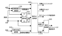
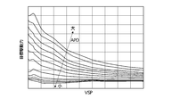
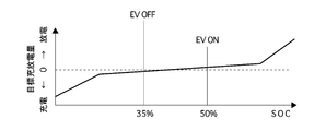
- FIG. 3 is a control block diagram illustrating an arithmetic processing program in the integrated controller according to the first embodiment. It is a figure which shows an example of the target driving force map used for target driving force calculation in the target driving force calculating part of FIG. It is a figure which shows the normal mode map used for selection of the target mode in the mode selection part of FIG. It is a figure which shows an example of the target charging / discharging amount map used for the calculation of target charging / discharging electric power in the target charging / discharging calculating part of FIG. It is a characteristic view showing the relationship between the rotation speed of the motor generator of Example 1, and a torque.
- FIG. 4 is a flowchart illustrating an engine start control process in a second start mode according to the first embodiment.
- 6 is a time chart illustrating a process for determining whether to start engine start control in a second start mode according to the first embodiment.
- 6 is a time chart illustrating an engine start control process in a second start mode according to the first embodiment.
- FIG. 1 is an overall system diagram showing a hybrid vehicle by rear wheel drive to which the engine start control device of the first embodiment is applied.
- the drive system of the hybrid vehicle in the first embodiment includes an engine E, a first clutch CL1, a motor generator MG, a second clutch CL2, an automatic transmission AT, a propeller shaft PS, It has a differential DF, a left drive shaft DSL, a right drive shaft DSR, a left rear wheel RL (drive wheel), and a right rear wheel RR (drive wheel).
- FL is the front left wheel
- FR is the front right wheel.
- the engine E is, for example, a gasoline engine, and the valve opening degree of the throttle valve is controlled based on a control command from the engine controller 1 described later.
- the engine output shaft is provided with a flywheel FW.
- the first clutch CL1 is a clutch interposed between the engine E and the motor generator MG, and the control created by the first clutch hydraulic unit 6 based on a control command from the first clutch controller 5 described later. Fastening / release including slip fastening is controlled by hydraulic pressure.
- the motor generator MG is a synchronous motor generator in which a permanent magnet is embedded in a rotor and a stator coil is wound around a stator, and the three-phase AC generated by the inverter 3 is generated based on a control command from a motor controller 2 described later. It is controlled by applying.
- the motor generator MG can operate as an electric motor that is driven to rotate by receiving power supplied from the battery 4 (hereinafter, this state is referred to as “power running”), or when the rotor is rotated by an external force.
- the rotor of the motor generator MG is connected to the input shaft of the automatic transmission AT via a damper (not shown).
- the second clutch CL2 is a clutch interposed between the motor generator MG and the left and right rear wheels RL and RR, and is generated by the second clutch hydraulic unit 8 based on a control command from the AT controller 7 described later.
- the fastening / release including slip fastening is controlled by the control hydraulic pressure.
- the automatic transmission AT is a transmission that automatically switches the stepped gear ratio such as 5 forward speeds, 1 reverse speed, etc. according to the vehicle speed, accelerator opening, etc., and the second clutch CL2 is newly added as a dedicated clutch
- some frictional engagement elements are used among a plurality of frictional engagement elements that are engaged at each gear stage of the automatic transmission AT. Details will be described later.
- the output shaft of the automatic transmission AT is connected to the left and right rear wheels RL and RR via a propeller shaft PS, a differential gear DF, a left drive shaft DSL, and a right drive shaft DSR as vehicle drive shafts.
- the first clutch CL1 and the second clutch CL2 are, for example, wet multi-plate clutches that can continuously control the oil flow rate and hydraulic pressure with a proportional solenoid.
- the brake unit 900 includes a hydraulic pressure pump and a plurality of electromagnetic valves, so-called brakes that secure the hydraulic pressure corresponding to the required braking torque by increasing the pump pressure, and control the wheel cylinder pressure by controlling the opening and closing of the electromagnetic valves of each wheel.
- Each wheel FR, FL, RR, RL is provided with a brake rotor 901 and a caliper 902, and generates a friction braking torque by the brake fluid pressure supplied from the brake unit 900.
- the type provided with the accumulator etc. may be sufficient as a hydraulic pressure source, and the structure provided with the electric caliper instead of the hydraulic brake may be sufficient.
- the first travel mode is an electric vehicle travel mode (hereinafter abbreviated as “EV travel mode”) as a motor use travel mode that travels using only the power of the motor generator MG as a power source with the first clutch CL1 opened. It is.
- the second travel mode is an engine use travel mode (hereinafter abbreviated as “HEV travel mode”) in which the first clutch CL1 is engaged and the engine E is included in the power source.
- the third travel mode is an abbreviated engine use slip travel mode (hereinafter referred to as “WSC travel mode”) in which the second clutch CL2 is slip-controlled while the first clutch CL1 is engaged and the engine E is included in the power source. ).
- This mode is a mode in which creep running can be achieved particularly when the battery SOC is low or the engine water temperature is low.
- the first clutch CL1 is engaged and the engine is started using the torque of the motor generator MG.
- the “HEV travel mode” has three travel modes of “engine travel mode”, “motor assist travel mode”, and “travel power generation mode”.
- engine running mode the drive wheels are moved using only engine E as the power source.
- motor assist travel mode the drive wheels are moved by using the engine E and the motor generator MG as power sources.
- the “running power generation mode” causes the motor generator MG to function as a generator at the same time as the drive wheels RR and RL are moved using the engine E as a power source.
- the motor generator MG is operated as a generator using the power of the engine E. Further, during deceleration operation, the braking energy is regenerated and generated by the motor generator MG and used for charging the battery 4. Further, as a further mode, there is a power generation mode in which the motor generator MG is operated as a generator using the power of the engine E when the vehicle is stopped.
- the hybrid vehicle control system includes an engine controller 1, a motor controller 2, an inverter 3, a battery 4, a first clutch controller 5, and a first clutch hydraulic unit 6.
- the AT controller 7, the second clutch hydraulic unit 8, the brake controller 9, and the integrated controller 10 are configured.
- the engine controller 1, the motor controller 2, the first clutch controller 5, the AT controller 7, the brake controller 9, and the integrated controller 10 are connected via a CAN communication line 11 that can exchange information with each other. Has been.
- the engine controller 1 inputs the engine speed information from the engine speed sensor 12, and controls the engine operating point (Ne: engine speed, Te: engine torque) according to the target engine torque command from the integrated controller 10, etc. For example, to a throttle valve actuator (not shown). More detailed engine control contents will be described later.
- Information such as the engine speed Ne is supplied to the integrated controller 10 via the CAN communication line 11.
- the motor controller 2 inputs information from the resolver 13 that detects the rotor rotational position of the motor generator MG, and according to a target motor generator torque command from the integrated controller 10 or the like, the motor operating point (Nm: motor generator) of the motor generator MG.
- a command for controlling the rotation speed (Tm: motor generator torque) is output to the inverter 3.
- the motor controller 2 monitors the battery SOC indicating the state of charge of the battery 4.
- the battery SOC information is used as control information for the motor generator MG and is supplied to the integrated controller 10 via the CAN communication line 11. Is done.
- the first clutch controller 5 inputs sensor information from the first clutch hydraulic pressure sensor 14 and the first clutch stroke sensor 15, and according to the first clutch control command from the integrated controller 10, the first clutch CL1 is engaged / released. A command to control is output to the first clutch hydraulic unit 6. Information on the first clutch stroke C1S is supplied to the integrated controller 10 via the CAN communication line 11.
- the AT controller 7 inputs sensor information from the accelerator opening sensor 16, the vehicle speed sensor 17, the second clutch hydraulic pressure sensor 18, and an inhibitor switch that outputs a signal corresponding to the position of the shift lever operated by the driver. 10 is output to the second clutch hydraulic unit 8 in the AT hydraulic control valve in response to the second clutch control command from 10.
- the transmission torque capacity of the second clutch CL2 is basically set to a value corresponding to the required drive torque, and is set to a capacity capable of transmitting the required drive torque to the drive wheels. When the accelerator pedal is released, the capacity is set so that the regenerative torque and creep torque can be transmitted.When the vehicle stops in EV driving mode and the brake pedal is depressed more than the specified value, the creep torque Is set to 0, the transmission torque capacity of the second clutch CL2 is also set to zero. Information on the accelerator pedal opening APO, the vehicle speed VSP, and the inhibitor switch is supplied to the integrated controller 10 via the CAN communication line 11.
- the brake controller 9 inputs sensor information from the wheel speed sensor 19 and the brake stroke sensor 20 that detect the respective wheel speeds of the four wheels. For example, when braking the brake, the driver requested braking torque obtained from the brake stroke BS is applied. When the regenerative braking torque is insufficient, the regenerative cooperative brake control is performed based on the regenerative cooperative control command from the integrated controller 10 so that the shortage is supplemented by the mechanical braking torque (braking torque by the friction brake). Needless to say, the brake fluid pressure can be arbitrarily generated not only by the brake fluid pressure corresponding to the driver requested braking torque but also by other control requirements.
- the integrated controller 10 manages the energy consumption of the entire vehicle and has a function for running the vehicle with the highest efficiency.
- the integrated controller 10 detects the motor rotational speed Nm, and the second clutch output rotational speed N2out.
- the information from the G sensor 10b for detecting the longitudinal acceleration and the information obtained through the CAN communication line 11 are input.
- the integrated controller 10 also controls the operation of the engine E according to the control command to the engine controller 1, the operation control of the motor generator MG based on the control command to the motor controller 2, and the first control command to the first clutch controller 5. Engagement / release control of the clutch CL1 and engagement / release control of the second clutch CL2 by a control command to the AT controller 7 are performed.
- the integrated controller 10 includes a target driving force calculation unit 100, a mode selection unit 200, a target charge / discharge calculation unit 300, an operating point command unit 400, and a shift control unit 500.
- the target driving force calculation unit 100 calculates a target driving force tFoO (driver required torque) from the accelerator pedal opening APO and the vehicle speed VSP using the target driving force map shown in FIG.
- the mode selection unit 200 has a normal mode map.
- FIG. 4 is a normal mode map of the first embodiment.
- the normal mode map has an EV travel mode, a WSC travel mode, and an HEV travel mode, and calculates the target mode from the accelerator pedal opening APO and the vehicle speed VSP. However, even if the EV travel mode is selected, if the battery SOC is equal to or lower than the predetermined value, the “HEV travel mode” or the “WSC travel mode” is forcibly set as the target mode.
- the HEV ⁇ WSC switching line has a rotational speed that is smaller than the idle rotational speed of the engine E when the automatic transmission AT is in the first speed in the region below the predetermined accelerator opening APO1. It is set in a region lower than the lower limit vehicle speed VSP1. Further, since a large driving force is required in a region where the accelerator opening APO1 is equal to or greater than the predetermined accelerator opening APO1, the WSC travel mode is set up to a vehicle speed VSP1 ′ region that is higher than the lower limit vehicle speed VSP1. When the battery SOC is low and the EV travel mode cannot be achieved, the WSC travel mode is selected even when starting.
- the target charge / discharge calculation unit 300 calculates the target charge / discharge power tP from the battery SOC using the target charge / discharge amount map shown in FIG.
- the EV drive mode area appears in the normal mode map of FIG. Once the EV area appears in the mode map, it continues to appear until the SOC drops below 35%.
- the EV drive mode area disappears in the normal mode map shown in FIG.
- the EV drive mode area disappears from within the mode map, this area continues to disappear until the SOC reaches 50%.
- the shift control unit 500 drives and controls the solenoid valve in the automatic transmission AT so as to achieve the target second clutch transmission torque capacity TCL2 * and the target shift speed according to the shift schedule shown in the shift map.
- a target gear position is set in advance based on the vehicle speed VSP and the accelerator pedal opening APO.
- the operating point command unit 400 uses the accelerator pedal opening APO, the target driving force tFoO (driver required torque), the target mode, the vehicle speed VSP, and the target charging / discharging power tP as transient targets for these operating points.
- the target engine torque, the target motor generator torque, the target second clutch transmission torque capacity TCL2 *, the target gear position of the automatic transmission AT, and the first clutch solenoid current command are calculated.
- the operating point command unit 400 is provided with an engine start control unit that starts the engine E when the EV travel mode is changed to the HEV travel mode.
- a case where the stopped engine E is started as a result of the driver's accelerator pedal operation is set as the first start mode, and factors other than the driver's accelerator pedal operation
- the case where the stopped engine E is started in (system required start) is set as the second start mode, and the engine is started in different start modes.
- the process of executing the second start mode will be described. For example, if any one of the following system start requests listed below is satisfied without stopping the driver's accelerator pedal operation while the engine is stopped, it is determined that the engine start request is in the second start mode. (1) When the oil temperature of the automatic transmission AT reaches a preset predetermined temperature (for example, 115 ° C. or higher), the engine is started in the second start mode. (2) When the oil temperature of the automatic transmission AT becomes equal to or lower than a predetermined temperature set in advance (for example, 15 ° C. or lower), the engine is started in the second start mode.
- a preset predetermined temperature for example, 115 ° C. or higher
- a predetermined temperature set in advance for example, 15 ° C. or lower
- the engine E When the coolant temperature of the engine E becomes equal to or lower than a predetermined temperature set in advance (for example, 40 ° C. or lower), the engine E is started in the second start mode. This is because, for example, when the hybrid vehicle executes a so-called idling stop at an intersection or the like, the engine E is prevented from entering a cold state due to the idling stop for a long time.
- a predetermined torque set in advance for example, 100 Nm or less
- FIG. 6 is a characteristic diagram showing the relationship between the rotation speed and torque of the motor generator of the first embodiment.
- the usable torque region of the motor generator MG decreases, and the motor generator 5 may not be able to start the engine E thereafter.
- the engine is started in the second start mode.
- the solid line a in FIG. 6 indicates the case where the output of the battery 4 is 50 kw
- the dotted line b indicates the case where the output of the battery 4 is 54 kw
- the alternate long and short dash line c indicates the case where the output of the battery 4 is 60 kw.
- the engine E is started in the second start mode. This is because, for example, the battery 4 is charged when the vehicle travels in the EV mode for a long time due to a traffic jam or the like.
- a predetermined speed set in advance for example, 100 km / h or higher
- the engine E is started in the second start mode. This is because the engine is started before the rotation of the motor generator MG becomes high.
- the engine E is started in the second start mode.
- the engine E is operated to ensure a negative pressure.
- the engine E is started in the second start mode when a predetermined idle stop prohibition condition is satisfied during the idle stop.
- the battery SOC of the battery 9 exceeds a predetermined value set in advance (for example, the battery SOC is 65% or more) while traveling on a downhill road, the engine E is started in the second start mode. . This is because the engine brake is used before the battery 4 is fully charged during traveling downhill and the regenerative torque is limited.
- the conditions (1) to (11) are examples of the engine start request conditions determined as the second start mode, and the engine start request conditions determined as the second start mode are these (1) to (11). It is not limited to the condition of (11).
- the transmission torque capacity of the first clutch CL1 is variably controlled so that the engine is quickly started.
- the transmission torque capacity of the first clutch CL1 when the transmission torque capacity of the first clutch CL1 is variably controlled when the engine is started, the transmission torque capacity is controlled to be lower in the second start mode than in the first start mode. Therefore, in the second start mode, it is possible to suppress a shock accompanying torque fluctuation due to engagement of the first clutch CL1. That is, at the time of engine start during traveling that is not intended by the driver, torque fluctuation at the time of engaging the first clutch can be suppressed, and the driver can be prevented from feeling uncomfortable due to shock accompanying torque fluctuation.
- FIG. 9 is a time chart showing an engine start control process in the second start mode of the first embodiment.
- the target transmission torque capacity of the second clutch CL2 is determined according to the required driving torque. In this case, the target transmission torque capacity is reduced to zero and the target transmission torque capacity of the first clutch CL1. Is increased from 0 to the target value for cranking.
- the target transmission torque capacity of the first clutch CL1 is increased toward a value at which the first clutch CL1 is completely engaged, and the target transmission torque capacity of the second clutch CL2 is Since the vehicle is still stopped, it remains 0.
- the motor generator MG is controlled in rotation speed so that the actual rotation speed becomes the target rotation speed from time t4 when engine cranking is started. This rotational speed control is performed from time t4 to time t6. Note that after time t6, the motor generator MG is torque-controlled so as to have the required drive torque. Note that the transmission torque capacity of the first clutch CL1 during cranking in the second start mode is set to be lower than that in the first start mode. Therefore, the cranking time in the second start mode is longer than the cranking time in the first start mode, but the torque fluctuation is small.
- the driver is braking by depressing the brake pedal.
- the engine is started in the second start mode.
- regenerative torque is generated in the motor generator MG in order to reproduce the coast torque at a predetermined vehicle speed or higher.
- the braking force corresponding to the driver's operation of the brake pedal is reduced by the regenerative torque, and is instead achieved by the friction braking force of the brake unit 900.
- the motor generator MG After that, the motor generator MG generates creep torque to reproduce the running state of the normal engine vehicle. That is, the torque generated by motor generator MG is switched from the negative regeneration torque to the positive drive torque. As a result, the driver can obtain a creep torque in the same manner as in a normal engine vehicle, and can achieve, for example, entering a garage or a slow running state only by operating a brake pedal.
- the engine generator when the creep torque is generated by the motor generator MG and the second start mode is requested, the engine is started with the creep torque being generated. At this time, since the transmission torque capacity of the second clutch CL2 is ensured so that creep torque can be transmitted, there is a problem that it is easy for the driver to feel uncomfortable due to torque fluctuation.
- the creep torque is decreased toward zero using that as a trigger.
- the engine start is started with the timing of starting the decrease of the creep torque as a trigger, the engine is started with the creep torque being high, and the transmission torque capacity of the second clutch CL2 is also high, which is given to the driver. Discomfort tends to increase.
- FIG. 7 is a flowchart illustrating an engine start control process in the second start mode according to the first embodiment.
- step S101 it is determined whether or not there is an engine start request in the second start mode. If there is an engine start request, the process proceeds to step S102, and otherwise, this step is repeated.
- step S102 it is determined whether or not the brake braking force is greater than the predetermined braking force B1 and the stop determination is ON. If the condition is satisfied, the process proceeds to step S103. Otherwise, the process proceeds to step S105.
- the stop determination means that it is determined that the vehicle has almost approached the stop state when the state where the vehicle speed is equal to or lower than a predetermined value continues for a predetermined time or longer. Therefore, the vehicle is not completely stopped.
- the vehicle speed is detected not by the wheel speed sensor or the like but by the resolver 13 that detects the motor generator rotation speed.
- the resolver 13 has an extremely high resolution as compared with a wheel speed sensor or the like, and can detect the vehicle speed with high accuracy even in an extremely low vehicle speed region.
- the creep torque applied to the motor generator MG is controlled so as to gradually decrease toward 0 Nm. This is because if the brake braking force, that is, the friction braking force by the brake unit 900 is larger than the predetermined braking force B1, it is considered that the driver intends to brake and torque fluctuations acting on the wheels can be suppressed to some extent.
- step S103 it is determined whether or not the state where the absolute value of the input torque (that is, the output torque of the motor generator MG) is 0 or less has passed the specified time T1. If it is determined that the time has passed, the process proceeds to step S106. Otherwise, the process proceeds to step S104. This is because if the state where the input torque absolute value is 0 or less elapses for the specified time T1 or longer, the application of creep torque is considered to be completely completed, and torque fluctuations associated with engine start can be suppressed.
- the input torque is determined using the command torque to the motor generator MG.
- the torque may be estimated based on the current value supplied to the motor generator MG, or the torque sensor. It is good also as a structure which detects input torque using etc.
- step S104 the engine is put on standby. That is, even if any of the predetermined conditions (1) to (11) is satisfied and an engine start request is made in the second start mode, engine start is prohibited. Thereby, when there is a possibility of torque fluctuation, it is possible to avoid a sense of discomfort given to the driver by avoiding engine start.
- step S105 it is determined whether or not the range position is the P range or the accelerator pedal is ON. If these conditions are satisfied, the process proceeds to step S106, and otherwise, the process returns to step S102. If the range position is the P range, the wheels are forcibly fixed by the operation of the parking lock mechanism, so that the influence of torque fluctuation can be suppressed even if input torque is generated. Further, when the accelerator pedal is turned on, the driver intends to start, and therefore the engine start in the first start mode is no longer appropriate.
- step S106 an engine start control process is started.
- the engine start control process is executed as described above with reference to FIG.
- FIG. 8 is a time chart showing a process for determining whether to start the engine start control in the second start mode according to the first embodiment.
- the first running state of the time chart is a state in which the vehicle speed is reduced to a predetermined vehicle speed during deceleration when the driver depresses the brake pedal. Further, the reduction of the regenerative torque is started from the regenerative torque output state by the motor generator MG according to the decrease of the vehicle speed, and the state is gradually switched to the friction braking force by the brake unit 900. This reduction in the regenerative torque reduces the regenerative torque control so that it becomes 0 when the vehicle speed reaches a predetermined value. It is assumed that the engine start request in the second start mode has already been made.
- the vehicle stop determination timer starts counting up. At this time, the vehicle speed is reduced to a predetermined vehicle speed.
- the vehicle stop determination timer is a timer that continuously counts up when the vehicle speed is below a predetermined vehicle speed and is reset when the vehicle speed increases. Simultaneously with the count-up of the vehicle stop determination timer, motor generator MG starts generating creep torque and gradually increases the torque.
- the feedback control must be performed, and the torque output from the motor generator MG also varies. Further, even if the second clutch CL2 is slip-controlled, the slip amount may also vary due to fluctuations in the input side rotational speed. In this case, the friction coefficient varies and the torque transmitted to the drive wheels varies, which may cause the driver to feel uncomfortable. Thus, in the first embodiment, the engine start is not permitted in a state where the motor generator MG outputs torque (that is, a state where the second clutch CL2 has a transmission torque capacity).
- the timer starts counting up.
- the transmission torque capacity of the second clutch CL2 is also set to 0 Nm.
- the engine start permission flag is turned ON, and engine start in the second start mode is started.
- the vehicle is also in a state where the vehicle speed is sufficiently lowered, and the brake pedal is depressed, so a stable vehicle stop state is ensured. Therefore, even if the motor generator torque is output for starting the engine, the torque is used only for starting the engine, so that the engine can be started without causing the driver to feel uncomfortable.
- step S103 when there is an engine start request in the second start mode and the absolute value of the output torque of the motor generator MG is equal to or less than a predetermined value, in the hybrid vehicle control device provided with the engine start control means) Allow engine cranking. Therefore, the torque fluctuation accompanying engine starting can be suppressed, and the discomfort felt by the driver can be suppressed.
- step S103 after the motor generator torque becomes zero, engine cranking is permitted after a predetermined time has elapsed. That is, it is possible to exclude a slow speed driving condition due to the inertia force of the vehicle with the passage of time, and to suppress a sense of discomfort given to the driver. In addition, it is possible to eliminate the influence of changes in road surface conditions and changes in the driver's brake operation.
- a resolver 13 (vehicle speed detecting means) for detecting the vehicle speed and step S102 (vehicle stop determining means) for determining whether or not the vehicle has stopped based on the detected vehicle speed are provided. Allow engine cranking after it is determined to be stopped. Therefore, the state of the vehicle can be detected with higher accuracy than in the case where the determination is made only with the motor generator torque and the friction braking force, and the torque fluctuation accompanying the engine start can be reliably suppressed. If the judgment is made only with the motor generator torque and the friction braking force, even if the creep torque remains, if the friction braking force is high, the vehicle may be judged to stop. This is because it gives the person a sense of discomfort.
- the vehicle speed detection means detects the vehicle speed based on a resolver 13 (rotation angle sensor) that detects the rotation speed of the motor generator. Therefore, since a sensor with extremely high resolution is used as compared with a wheel speed sensor or the like, the vehicle stop state can be accurately determined in the extremely low vehicle speed region.
- a resolver 13 rotation angle sensor
- the present invention is applied to a hybrid vehicle, but the present invention can be similarly applied to a vehicle having only an engine or only a motor.
- the engine start permission condition the state where the output torque of the motor generator MG is 0 continues for a specified time or more, but the brake braking force is equal to or greater than a value obtained by adding a predetermined value to the motor generator output torque. If so, the engine may be allowed to start. This is because if the drive wheels are securely fixed and the motor generator torque is small, even if torque fluctuations occur, the driver will not feel uncomfortable.
- the FR type hybrid vehicle has been described.
- an FF type hybrid vehicle may be used.
Landscapes
- Engineering & Computer Science (AREA)
- Chemical & Material Sciences (AREA)
- Combustion & Propulsion (AREA)
- Mechanical Engineering (AREA)
- Transportation (AREA)
- General Engineering & Computer Science (AREA)
- Automation & Control Theory (AREA)
- Power Engineering (AREA)
- Electric Propulsion And Braking For Vehicles (AREA)
- Hybrid Electric Vehicles (AREA)
Abstract
Description
本発明は、上記問題に着目してなされたもので、ショックを抑制しつつエンジン始動を達成可能なハイブリッド車両の制御装置を提供することを目的とする。
CL1 第1クラッチ
MG モータジェネレータ
CL2 第2クラッチ
AT 自動変速機
1 エンジンコントローラ
2 モータコントローラ
3 インバータ
4 バッテリ
5 第1クラッチコントローラ
6 第1クラッチ油圧ユニット
7 ATコントローラ
8 第2クラッチ油圧ユニット
9 ブレーキコントローラ
10 統合コントローラ
24 ブレーキ油圧センサ
100 目標駆動力演算部
200 モード選択部
300 目標充放電演算部
400 動作点指令部
500 変速制御部
まず、ハイブリッド車両の駆動系構成を説明する。図1は実施例1のエンジン始動制御装置が適用された後輪駆動によるハイブリッド車両を示す全体システム図である。実施例1におけるハイブリッド車の駆動系は、図1に示すように、エンジンEと、第1クラッチCL1と、モータジェネレータMGと、第2クラッチCL2と、自動変速機ATと、プロペラシャフトPSと、ディファレンシャルDFと、左ドライブシャフトDSLと、右ドライブシャフトDSRと、左後輪RL(駆動輪)と、右後輪RR(駆動輪)と、を有する。尚、FLは左前輪、FRは右前輪である。
(1)自動変速機ATの油温が予め設定された所定温度(例えば115℃以上)となった場合には第2始動モードでエンジン始動を行う。
(2)自動変速機ATの油温が予め設定された所定温度以下(例えば15℃以下)となった場合には第2始動モードでエンジン始動を行う。これは、例えば、ハイブリッド車両が交差点等でいわゆるアイドリングストップを実行する場合、長時間のアイドリングストップによる自動変速機ATの油温の過度の低下を防止するためである。
(3)エンジンEの冷却水温が予め設定された所定温度以上(例えば120℃以上)となった場合には第2始動モードでエンジン始動を行う。
(5)モータジェネレータMGの出力可能なトルクが、予め設定された所定トルク以下(例えば、100Nm以下)になった場合には第2始動モードでエンジンEの始動を行う。これは、モータジェネレータMGの過熱により、モータジェネレータMGから出力可能なモータトルクが前記所定トルクよりも低下すると、以後はモータジェネレータMGによりエンジン1を始動できなくなる虞があるためである。
(6)バッテリ4の出力可能な電力が、予め設定された所定電力以下(例えば20kw以下)になった場合には第2始動モードでエンジン始動を行う。図6は実施例1のモータジェネレータの回転数とトルクの関係を表す特性図である。バッテリ4の温度上昇、またはバッテリ4の温度低下により、バッテリ4から出力可能な電力が低下すると、図6に示すように、回転数が大きくなるほど、モータジェネレータMGで出力可能なモータトルクが低下する。そこで、バッテリ4から出力可能な電力が前記所定電力以下に低下した場合には、モータジェネレータMGの使用可能なトルク領域が減少し、以後モータジェネレータ5によりエンジンEを始動できなくなる虞があるため、第2始動モードによるエンジン始動を行う。ここで、図6中の実線aはバッテリ4の出力が50kwの場合、点線bはバッテリ4の出力が54kwの場合、一点鎖線cはバッテリ4の出力が60kwの場合を示している。
(8)車速が予め設定された所定速度以上(例えば100km/h以上)となった場合には第2始動モードでエンジンEの始動を行う。これは、モータジェネレータMGの回転が高回転となる前にエンジン始動するためである。
(9)負圧ポンプの負圧の低下によりエンジン始動要求がある場合には第2始動モードでエンジンEの始動を行う。これは、エンジンEを運転させて負圧を確保するためである。
(10)ハイブリッド車両が、交差点等でいわゆるアイドルストップを実行する場合、アイドルストップ中に所定のアイドルストップ禁止条件が成立した場合には第2始動モードでエンジンEの始動を行う。
(11)降坂路を走行中に、バッテリ9のバッテリSOCが、予め設定された所定値以上(例えばバッテリSOCが65%以上)になった場合には第2始動モードでエンジンEの始動を行う。これは、降坂路を走行中にバッテリ4が満充電され、回生トルクが制限される前に、エンジンブレーキを利用するためである。
時刻t4において、エンジン始動要求があると、第2クラッチCL2の目標伝達トルク容量は要求駆動トルクに応じて決定されることから、この場合はゼロまで低下させ、第1クラッチCL1の目標伝達トルク容量を0からクランキング時の目標値まで増加させる。そして、時刻t2において、エンジン回転数とモータジェネレータ回転数とが同期すると、第1クラッチCL1の目標伝達トルク容量を完全締結となる値に向けて増加させ、第2クラッチCL2の目標伝達トルク容量は車両停止が継続しているため0のままとする。
ステップS102では、ブレーキ制動力が所定制動力B1よりも大きく、かつ、停車判定がONか否かを判断し、条件が成立したときはステップS103へ進み、それ以外のときはステップS105へ進む。ここで、停車判定とは、車速が所定値以下となった状態が所定時間以上継続した場合に、ほぼ車両停止状態に近づいたと判定することをいう。よって、完全に車両停止しているとは限らない。また、車速は車輪速センサ等ではなく、モータジェネレータ回転数を検出するレゾルバ13により検出する。レゾルバ13は車輪速センサ等に比べて分解能が極めて高く、極低車速領域であっても精度良く車速を検出することができるからである。モータジェネレータ側の制御処理において、この停車判定がONとされると、モータジェネレータMGに付与されていたクリープトルクは0Nmに向けて徐々に減少するように制御される。ブレーキ制動力、すなわちブレーキユニット900による摩擦制動力が所定制動力B1よりも大きければ、運転者に制動意図があり、かつ、車輪に作用するトルク変動がある程度抑制できると考えられるからである。
(1)モータジェネレータMGと駆動輪との間に設けられた第2クラッチCL2と、エンジン始動要求があるときは、第2クラッチCL2を締結し、モータジェネレータMGによりエンジン始動を行なう統合コントローラ10(エンジン始動制御手段)と、を備えたハイブリッド車両の制御装置において、ステップS103では、第2始動モードによるエンジン始動要求があり、かつ、モータジェネレータMGの出力トルクの絶対値が所定値以下になると、エンジンクランキングを許可する。
よって、エンジン始動に伴うトルク変動を抑制することができ、運転者が感じる違和感を抑制することができる。
すなわち、時間の経過により車両の慣性力などによる微速走行条件を除外することができ、運転者に与える違和感を抑制することができる。また、路面の状況変化や運転者のブレーキ操作変動による影響を排除することができる。
よって、モータジェネレータトルクと摩擦制動力のみで判断する場合に比べて、車両の状態を精度良く検出することができ、エンジン始動に伴うトルク変動を確実に抑制することができる。仮に、モータジェネレータトルクと摩擦制動力のみで判断してしまうと、クリープトルクが残った状態であっても摩擦制動力が高ければ車両停止判断を行なうおそれがあり、エンジン始動に伴うトルク変動によって運転者に違和感を与えてしまうからである。
よって、車輪速センサ等に比べて極めて分解能の高いセンサを用いるため、極低車速領域において精度良く車両停止状態を判定することができる。
Claims (4)
- モータジェネレータと駆動輪との間に設けられたクラッチと、
エンジン始動要求があるときは、前記クラッチを締結し、前記モータジェネレータによりエンジン始動を行なうエンジン始動制御手段と、
を備えたハイブリッド車両の制御装置において、
前記エンジン始動制御手段は、エンジン始動要求があり、かつ、前記モータジェネレータの出力トルク絶対値が所定値以下になると、エンジン始動を許可することを特徴とするハイブリッド車両の制御装置。 - 請求項1に記載のハイブリッド車両の制御装置において、
前記所定値はゼロであり、
前記エンジン始動制御手段は、前記モータジェネレータの出力トルクがゼロの状態が予め設定した規定時間経過後にエンジン始動を許可することを特徴とするハイブリッド車両の制御装置。 - 請求項1または2に記載のハイブリッド車両の制御装置において、
車速を検出する車速検出手段と、
該検出された車速に基づいて車両が停止したか否かを判断する車両停止判断手段を設け、
前記エンジン始動制御手段は、車両停止と判断されてからエンジン始動を許可することを特徴とするハイブリッド車両の制御装置。 - 請求項3に記載のハイブリッド車両の制御装置において、
前記車速検出手段は、モータジェネレータの回転数を検出する回転角センサに基づいて車速を検出することを特徴とするハイブリッド車両の制御装置。
Priority Applications (5)
| Application Number | Priority Date | Filing Date | Title |
|---|---|---|---|
| US14/127,023 US9216731B2 (en) | 2011-06-30 | 2012-06-19 | Control device for hybrid vehicle |
| KR1020137034657A KR101485286B1 (ko) | 2011-06-30 | 2012-06-19 | 하이브리드 차량의 제어 장치 |
| JP2013522765A JP5561435B2 (ja) | 2011-06-30 | 2012-06-19 | ハイブリッド車両の制御装置 |
| CN201280023233.2A CN103534156B (zh) | 2011-06-30 | 2012-06-19 | 混合动力车辆的控制装置 |
| EP12804717.2A EP2727787B1 (en) | 2011-06-30 | 2012-06-19 | Control device for hybrid vehicle |
Applications Claiming Priority (2)
| Application Number | Priority Date | Filing Date | Title |
|---|---|---|---|
| JP2011145127 | 2011-06-30 | ||
| JP2011-145127 | 2011-06-30 |
Publications (1)
| Publication Number | Publication Date |
|---|---|
| WO2013002062A1 true WO2013002062A1 (ja) | 2013-01-03 |
Family
ID=47423960
Family Applications (1)
| Application Number | Title | Priority Date | Filing Date |
|---|---|---|---|
| PCT/JP2012/065577 Ceased WO2013002062A1 (ja) | 2011-06-30 | 2012-06-19 | ハイブリッド車両の制御装置 |
Country Status (6)
| Country | Link |
|---|---|
| US (1) | US9216731B2 (ja) |
| EP (1) | EP2727787B1 (ja) |
| JP (1) | JP5561435B2 (ja) |
| KR (1) | KR101485286B1 (ja) |
| CN (1) | CN103534156B (ja) |
| WO (1) | WO2013002062A1 (ja) |
Cited By (1)
| Publication number | Priority date | Publication date | Assignee | Title |
|---|---|---|---|---|
| JP2015009680A (ja) * | 2013-06-28 | 2015-01-19 | 富士重工業株式会社 | ハイブリッド車の制御装置 |
Families Citing this family (28)
| Publication number | Priority date | Publication date | Assignee | Title |
|---|---|---|---|---|
| KR101826536B1 (ko) | 2012-08-07 | 2018-02-07 | 현대자동차 주식회사 | 차량의 아이들 스톱 제어 방법 및 장치 |
| JP6119966B2 (ja) * | 2012-12-21 | 2017-04-26 | 三菱自動車工業株式会社 | ハイブリッド車の走行モード切換制御装置 |
| JP5712999B2 (ja) * | 2012-12-26 | 2015-05-07 | トヨタ自動車株式会社 | ハイブリッド自動車 |
| JP6255767B2 (ja) * | 2013-07-24 | 2018-01-10 | 三菱自動車工業株式会社 | 自動車の制御装置 |
| US9458811B2 (en) * | 2013-10-18 | 2016-10-04 | Ford Global Technologies, Llc | Hybrid vehicle engine start |
| FR3013660B1 (fr) | 2013-11-28 | 2017-05-26 | Renault Sas | Procede et systeme de demarrage d'un moteur thermique |
| US9493075B2 (en) * | 2014-03-25 | 2016-11-15 | Ford Global Technologies, Llc | Regenerative braking control system and method |
| JP6108313B2 (ja) * | 2014-07-01 | 2017-04-05 | 本田技研工業株式会社 | ハイブリッド車両におけるエンジン始動制御装置 |
| WO2016092587A1 (ja) * | 2014-12-08 | 2016-06-16 | 日産自動車株式会社 | 制駆動力制御装置及び制駆動力制御方法 |
| JP6252519B2 (ja) * | 2015-03-06 | 2017-12-27 | トヨタ自動車株式会社 | ハイブリッド車の制御装置 |
| JP6292208B2 (ja) * | 2015-11-05 | 2018-03-14 | トヨタ自動車株式会社 | ハイブリッド車両 |
| JP6406226B2 (ja) * | 2015-11-27 | 2018-10-17 | 株式会社デンソー | 車両制御装置 |
| US10569758B2 (en) * | 2016-02-26 | 2020-02-25 | Ford Global Technologies, Llc | System and method for modeling and estimating engine cranking torque disturbances during starts and stops |
| JP6733288B2 (ja) * | 2016-04-27 | 2020-07-29 | いすゞ自動車株式会社 | ハイブリッド車両 |
| US20170363026A1 (en) * | 2016-06-20 | 2017-12-21 | Caterpillar Inc. | Methods and systems for operating an engine |
| KR101795299B1 (ko) | 2016-09-08 | 2017-12-01 | 현대자동차주식회사 | 주행성능유지를 위한 엔진 기동성 확보 방법 및 하이브리드 차량 |
| KR20180070341A (ko) * | 2016-12-16 | 2018-06-26 | 현대자동차주식회사 | 하이브리드 자동차 및 그를 위한 모드 전환 제어 방법 |
| DE102017200982B4 (de) * | 2017-01-23 | 2021-09-16 | Audi Ag | Verfahren zum Betreiben einer Antriebseinrichtung für ein Kraftfahrzeug sowie entsprechende Antriebseinrichtung |
| JP6725745B2 (ja) * | 2017-03-15 | 2020-07-22 | 日立オートモティブシステムズ株式会社 | 車両制御装置及び車両制御方法 |
| RU2748924C1 (ru) * | 2017-12-15 | 2021-06-01 | Ниссан Мотор Ко., Лтд. | Способ управления силовой установкой и силовая установка |
| JP6616817B2 (ja) * | 2017-12-27 | 2019-12-04 | 株式会社Subaru | 車両用制御装置 |
| KR102610753B1 (ko) * | 2018-12-11 | 2023-12-08 | 현대자동차주식회사 | 하이브리드 차량 제어 장치, 그를 포함한 시스템 및 그 방법 |
| DE102019201790A1 (de) * | 2019-02-12 | 2020-08-13 | Zf Friedrichshafen Ag | Verfahren und Steuereinheit zum Betrieb eines Kraftfahrzeug-Antriebsstranges |
| US11598305B2 (en) | 2019-11-27 | 2023-03-07 | Caterpillar Inc. | Engine idling reduction system |
| CN111976696B (zh) * | 2020-01-19 | 2021-11-16 | 蜂巢传动科技河北有限公司 | 混合动力车辆的发动机控制方法及装置 |
| CN112706754B (zh) * | 2021-01-26 | 2022-07-29 | 上汽通用五菱汽车股份有限公司 | 混合动力车辆及发动机启动方法和计算机可读存储介质 |
| JP2024000762A (ja) * | 2022-06-21 | 2024-01-09 | マツダ株式会社 | ハイブリッド車両の制御装置 |
| JP7797976B2 (ja) * | 2022-07-14 | 2026-01-14 | トヨタ自動車株式会社 | 車両の制御装置 |
Citations (9)
| Publication number | Priority date | Publication date | Assignee | Title |
|---|---|---|---|---|
| JP3116685B2 (ja) | 1993-10-14 | 2000-12-11 | 三菱自動車工業株式会社 | 車両用左右駆動力調整装置 |
| JP2001304008A (ja) * | 2000-04-25 | 2001-10-31 | Nissan Motor Co Ltd | 車両の制御装置 |
| JP2005232993A (ja) * | 2004-02-17 | 2005-09-02 | Toyota Motor Corp | 車両およびその制御方法 |
| JP2008265615A (ja) * | 2007-04-23 | 2008-11-06 | Toyota Motor Corp | 車両およびその制御方法 |
| JP2009149213A (ja) * | 2007-12-20 | 2009-07-09 | Toyota Motor Corp | 車両用動力伝達装置の制御装置 |
| JP2010143296A (ja) * | 2008-12-17 | 2010-07-01 | Nissan Motor Co Ltd | ハイブリッド車両の制御装置 |
| JP2010202151A (ja) * | 2009-03-06 | 2010-09-16 | Nissan Motor Co Ltd | ハイブリッド車両のエンジン始動制御装置 |
| JP2010234923A (ja) * | 2009-03-30 | 2010-10-21 | Aisin Aw Co Ltd | ハイブリッド駆動装置 |
| JP2010255504A (ja) * | 2009-04-24 | 2010-11-11 | Toyota Motor Corp | ハイブリッド車両の制御装置 |
Family Cites Families (15)
| Publication number | Priority date | Publication date | Assignee | Title |
|---|---|---|---|---|
| JP3214427B2 (ja) * | 1997-12-12 | 2001-10-02 | トヨタ自動車株式会社 | ハイブリッド車の駆動制御装置 |
| JP3498593B2 (ja) * | 1998-10-15 | 2004-02-16 | 日産自動車株式会社 | ハイブリッド車両の制御装置 |
| US6823954B2 (en) * | 2001-05-18 | 2004-11-30 | Honda Giken Kogyo Kabushiki Kaisha | Control system for hybrid vehicle |
| JP3912368B2 (ja) * | 2003-12-05 | 2007-05-09 | 日産自動車株式会社 | ハイブリッド変速機搭載車のエンジン始動方法 |
| JP4341610B2 (ja) | 2005-11-09 | 2009-10-07 | 日産自動車株式会社 | ハイブリッド車両のエンジン再始動制御装置 |
| JP2007261498A (ja) * | 2006-03-29 | 2007-10-11 | Nissan Motor Co Ltd | ハイブリッド車両の伝動状態切り替え制御装置 |
| US8387730B2 (en) * | 2006-11-30 | 2013-03-05 | Azure Dynamics, Inc. | Method and apparatus for starting an engine in a hybrid vehicle |
| US7617808B2 (en) * | 2007-06-05 | 2009-11-17 | Deepak Aswani | Engine start detection in a hybrid electric vehicle |
| DE102007061730A1 (de) * | 2007-12-20 | 2009-06-25 | Robert Bosch Gmbh | Verfahren und Vorrichtung zur Ermittlung und Prädiktion eines zum Starten eines Verbrennungsmotors notwendigen Startmoments oder Startmomentenverlaufs |
| DE102008001159A1 (de) * | 2008-04-14 | 2009-10-15 | Robert Bosch Gmbh | Verfahren und Steuerungsmodul zum Steuern des Antriebsmodus eines Hybridantriebs zur Verhinderung von Ruckbewegungen |
| JP5307604B2 (ja) * | 2009-04-08 | 2013-10-02 | アイシン・エーアイ株式会社 | 車両の動力伝達制御装置 |
| DE102009027001A1 (de) * | 2009-06-17 | 2010-12-23 | Robert Bosch Gmbh | Verfahren und Vorrichtung zur Bestimmung des Beginns einer Startphase eines Verbrennungsmotors in einem Hybridfahrzeug |
| US8565990B2 (en) * | 2009-11-13 | 2013-10-22 | Ford Global Technologies, Llc. | Vehicle and method for controlling engine start in a vehicle |
| US8731753B2 (en) * | 2010-09-30 | 2014-05-20 | GM Global Technology Operations LLC | Control of engine start for a hybrid system |
| EP2634060B1 (en) * | 2010-10-26 | 2023-12-13 | Nissan Motor Co., Ltd. | Control device and control method for hybrid vehicle |
-
2012
- 2012-06-19 CN CN201280023233.2A patent/CN103534156B/zh active Active
- 2012-06-19 JP JP2013522765A patent/JP5561435B2/ja not_active Expired - Fee Related
- 2012-06-19 KR KR1020137034657A patent/KR101485286B1/ko not_active Expired - Fee Related
- 2012-06-19 WO PCT/JP2012/065577 patent/WO2013002062A1/ja not_active Ceased
- 2012-06-19 EP EP12804717.2A patent/EP2727787B1/en not_active Not-in-force
- 2012-06-19 US US14/127,023 patent/US9216731B2/en active Active
Patent Citations (9)
| Publication number | Priority date | Publication date | Assignee | Title |
|---|---|---|---|---|
| JP3116685B2 (ja) | 1993-10-14 | 2000-12-11 | 三菱自動車工業株式会社 | 車両用左右駆動力調整装置 |
| JP2001304008A (ja) * | 2000-04-25 | 2001-10-31 | Nissan Motor Co Ltd | 車両の制御装置 |
| JP2005232993A (ja) * | 2004-02-17 | 2005-09-02 | Toyota Motor Corp | 車両およびその制御方法 |
| JP2008265615A (ja) * | 2007-04-23 | 2008-11-06 | Toyota Motor Corp | 車両およびその制御方法 |
| JP2009149213A (ja) * | 2007-12-20 | 2009-07-09 | Toyota Motor Corp | 車両用動力伝達装置の制御装置 |
| JP2010143296A (ja) * | 2008-12-17 | 2010-07-01 | Nissan Motor Co Ltd | ハイブリッド車両の制御装置 |
| JP2010202151A (ja) * | 2009-03-06 | 2010-09-16 | Nissan Motor Co Ltd | ハイブリッド車両のエンジン始動制御装置 |
| JP2010234923A (ja) * | 2009-03-30 | 2010-10-21 | Aisin Aw Co Ltd | ハイブリッド駆動装置 |
| JP2010255504A (ja) * | 2009-04-24 | 2010-11-11 | Toyota Motor Corp | ハイブリッド車両の制御装置 |
Non-Patent Citations (1)
| Title |
|---|
| See also references of EP2727787A4 |
Cited By (1)
| Publication number | Priority date | Publication date | Assignee | Title |
|---|---|---|---|---|
| JP2015009680A (ja) * | 2013-06-28 | 2015-01-19 | 富士重工業株式会社 | ハイブリッド車の制御装置 |
Also Published As
| Publication number | Publication date |
|---|---|
| KR101485286B1 (ko) | 2015-01-21 |
| EP2727787A4 (en) | 2016-08-03 |
| CN103534156B (zh) | 2016-08-31 |
| US20140136039A1 (en) | 2014-05-15 |
| JPWO2013002062A1 (ja) | 2015-02-23 |
| EP2727787A1 (en) | 2014-05-07 |
| US9216731B2 (en) | 2015-12-22 |
| KR20140010191A (ko) | 2014-01-23 |
| EP2727787B1 (en) | 2017-10-04 |
| CN103534156A (zh) | 2014-01-22 |
| JP5561435B2 (ja) | 2014-07-30 |
Similar Documents
| Publication | Publication Date | Title |
|---|---|---|
| JP5561435B2 (ja) | ハイブリッド車両の制御装置 | |
| JP5585859B2 (ja) | 車両の発進制御装置 | |
| JP5501260B2 (ja) | 車両の制御装置 | |
| JP5383626B2 (ja) | 車両の制御装置 | |
| JP5496854B2 (ja) | 車両の制御装置 | |
| JP5693151B2 (ja) | 車両の制御装置 | |
| JP5496855B2 (ja) | 車両の制御装置 | |
| JP5742248B2 (ja) | 車両の制御装置 | |
| JP5747525B2 (ja) | 車両の制御装置 | |
| JP2013035441A (ja) | ハイブリッド車両の制御装置 | |
| JP5672950B2 (ja) | 車両の制御装置 | |
| JP2009035188A (ja) | ハイブリッド車両の制御装置 | |
| JP2010155590A (ja) | ハイブリッド車両の発進制御装置。 | |
| JP5724291B2 (ja) | 車両の制御装置 | |
| WO2014034319A1 (ja) | ニュートラル判定装置および車両の制御装置 | |
| JP5092363B2 (ja) | 車両の発進制御装置 | |
| JP2012091601A (ja) | 車両の制御装置 | |
| JP5874165B2 (ja) | ハイブリッド車両の制御装置 | |
| JP5141535B2 (ja) | ハイブリッド車両の制御装置 | |
| JP5309676B2 (ja) | 車両の発進制御装置 | |
| JP5950038B2 (ja) | ハイブリッド車両の制御装置 | |
| JP5699535B2 (ja) | 車両の制御装置 | |
| JP5741015B2 (ja) | 車両の制御装置 | |
| JP5691382B2 (ja) | ハイブリッド車両の制御装置 |
Legal Events
| Date | Code | Title | Description |
|---|---|---|---|
| 121 | Ep: the epo has been informed by wipo that ep was designated in this application |
Ref document number: 12804717 Country of ref document: EP Kind code of ref document: A1 |
|
| ENP | Entry into the national phase |
Ref document number: 2013522765 Country of ref document: JP Kind code of ref document: A |
|
| REEP | Request for entry into the european phase |
Ref document number: 2012804717 Country of ref document: EP |
|
| WWE | Wipo information: entry into national phase |
Ref document number: 2012804717 Country of ref document: EP |
|
| WWE | Wipo information: entry into national phase |
Ref document number: 14127023 Country of ref document: US |
|
| ENP | Entry into the national phase |
Ref document number: 20137034657 Country of ref document: KR Kind code of ref document: A |
|
| NENP | Non-entry into the national phase |
Ref country code: DE |