WO2013005771A1 - 転がり軸受 - Google Patents
転がり軸受 Download PDFInfo
- Publication number
- WO2013005771A1 WO2013005771A1 PCT/JP2012/067079 JP2012067079W WO2013005771A1 WO 2013005771 A1 WO2013005771 A1 WO 2013005771A1 JP 2012067079 W JP2012067079 W JP 2012067079W WO 2013005771 A1 WO2013005771 A1 WO 2013005771A1
- Authority
- WO
- WIPO (PCT)
- Prior art keywords
- separator
- rolling bearing
- bearing according
- rolling
- circumferential direction
- Prior art date
- Legal status (The legal status is an assumption and is not a legal conclusion. Google has not performed a legal analysis and makes no representation as to the accuracy of the status listed.)
- Ceased
Links
Images









Classifications
-
- F—MECHANICAL ENGINEERING; LIGHTING; HEATING; WEAPONS; BLASTING
- F16—ENGINEERING ELEMENTS AND UNITS; GENERAL MEASURES FOR PRODUCING AND MAINTAINING EFFECTIVE FUNCTIONING OF MACHINES OR INSTALLATIONS; THERMAL INSULATION IN GENERAL
- F16C—SHAFTS; FLEXIBLE SHAFTS; ELEMENTS OR CRANKSHAFT MECHANISMS; ROTARY BODIES OTHER THAN GEARING ELEMENTS; BEARINGS
- F16C33/00—Parts of bearings; Special methods for making bearings or parts thereof
- F16C33/30—Parts of ball or roller bearings
- F16C33/37—Loose spacing bodies
- F16C33/3706—Loose spacing bodies with concave surfaces conforming to the shape of the rolling elements, e.g. the spacing bodies are in sliding contact with the rolling elements
-
- F—MECHANICAL ENGINEERING; LIGHTING; HEATING; WEAPONS; BLASTING
- F16—ENGINEERING ELEMENTS AND UNITS; GENERAL MEASURES FOR PRODUCING AND MAINTAINING EFFECTIVE FUNCTIONING OF MACHINES OR INSTALLATIONS; THERMAL INSULATION IN GENERAL
- F16C—SHAFTS; FLEXIBLE SHAFTS; ELEMENTS OR CRANKSHAFT MECHANISMS; ROTARY BODIES OTHER THAN GEARING ELEMENTS; BEARINGS
- F16C19/00—Bearings with rolling contact, for exclusively rotary movement
- F16C19/02—Bearings with rolling contact, for exclusively rotary movement with bearing balls essentially of the same size in one or more circular rows
- F16C19/20—Bearings with rolling contact, for exclusively rotary movement with bearing balls essentially of the same size in one or more circular rows with loose spacing bodies, e.g. balls, between the bearing balls
-
- F—MECHANICAL ENGINEERING; LIGHTING; HEATING; WEAPONS; BLASTING
- F16—ENGINEERING ELEMENTS AND UNITS; GENERAL MEASURES FOR PRODUCING AND MAINTAINING EFFECTIVE FUNCTIONING OF MACHINES OR INSTALLATIONS; THERMAL INSULATION IN GENERAL
- F16C—SHAFTS; FLEXIBLE SHAFTS; ELEMENTS OR CRANKSHAFT MECHANISMS; ROTARY BODIES OTHER THAN GEARING ELEMENTS; BEARINGS
- F16C33/00—Parts of bearings; Special methods for making bearings or parts thereof
- F16C33/30—Parts of ball or roller bearings
- F16C33/37—Loose spacing bodies
-
- F—MECHANICAL ENGINEERING; LIGHTING; HEATING; WEAPONS; BLASTING
- F16—ENGINEERING ELEMENTS AND UNITS; GENERAL MEASURES FOR PRODUCING AND MAINTAINING EFFECTIVE FUNCTIONING OF MACHINES OR INSTALLATIONS; THERMAL INSULATION IN GENERAL
- F16C—SHAFTS; FLEXIBLE SHAFTS; ELEMENTS OR CRANKSHAFT MECHANISMS; ROTARY BODIES OTHER THAN GEARING ELEMENTS; BEARINGS
- F16C33/00—Parts of bearings; Special methods for making bearings or parts thereof
- F16C33/30—Parts of ball or roller bearings
- F16C33/66—Special parts or details in view of lubrication
- F16C33/6696—Special parts or details in view of lubrication with solids as lubricant, e.g. dry coatings, powder
-
- F—MECHANICAL ENGINEERING; LIGHTING; HEATING; WEAPONS; BLASTING
- F16—ENGINEERING ELEMENTS AND UNITS; GENERAL MEASURES FOR PRODUCING AND MAINTAINING EFFECTIVE FUNCTIONING OF MACHINES OR INSTALLATIONS; THERMAL INSULATION IN GENERAL
- F16C—SHAFTS; FLEXIBLE SHAFTS; ELEMENTS OR CRANKSHAFT MECHANISMS; ROTARY BODIES OTHER THAN GEARING ELEMENTS; BEARINGS
- F16C19/00—Bearings with rolling contact, for exclusively rotary movement
- F16C19/02—Bearings with rolling contact, for exclusively rotary movement with bearing balls essentially of the same size in one or more circular rows
- F16C19/04—Bearings with rolling contact, for exclusively rotary movement with bearing balls essentially of the same size in one or more circular rows for radial load mainly
- F16C19/06—Bearings with rolling contact, for exclusively rotary movement with bearing balls essentially of the same size in one or more circular rows for radial load mainly with a single row or balls
Definitions
- the present invention relates to a rolling bearing in which a plurality of rolling elements are arranged between inner and outer rings and a plurality of separators are interposed in the circumferential direction between the rolling elements, particularly in a high temperature atmosphere such as a tenter clip bearing of a film stretching machine, or a vacuum
- the present invention relates to a rolling bearing suitable for use in an atmosphere.
- tenter clip bearings for film stretching machines are generally used in a high temperature atmosphere of 150 to 250 ° C., heat resistance is required.
- Patent Document 1 A rolling bearing using such a separator is disclosed in Patent Document 1 or Patent Document 2.
- JP 2000-320548 A Japanese Patent Laying-Open No. 2005-3178
- the separator is formed of a solid lubricant, the separator is heavily worn.
- the rolling elements may fall off the inner and outer rings. Occurs.
- the present invention is intended to provide a rolling bearing capable of effectively preventing the rolling elements from falling off from the inner and outer rings even when the wear of the separator progresses.
- the present invention provides a rolling bearing in which a plurality of rolling elements are arranged between inner and outer rings, and a plurality of prismatic separators are interposed between the rolling elements in the circumferential direction.
- a band having a width smaller than the width in the circumferential direction of the separator is integrated with at least one of the opposing surfaces of the inner and outer rings excluding the circumferential surface in contact with the rolling elements.
- a typical example of the rolling bearing of the present invention is a deep groove ball bearing.
- the band is made of stainless steel, brass, or SS material plated, and is preferably made of stainless steel or brass in consideration of slipperiness and corrosion resistance.
- the separator is formed of a solid lubricant such as graphite.
- the separator is formed of graphite, it is preferable that the graphite content is 80 to 98 vol%.
- the solid lubricant has a bending strength of 4 to 15 MPa and a specific wear amount of 1.5 to 2.5 ⁇ 10 ⁇ 5 mm 3 / (N / m).
- the width of the band is set so that the balls do not fall off the inner and outer rings even if the separator is worn.
- the anti-slip effect between the separator and the band is improved by providing irregularities on the inner surface of the band on the side of the separator.
- the separator is formed so that the circumferential length becomes shorter toward the inner diameter side, and the surface facing the outer ring is at least partially formed as a flat surface or a polygonal surface in the circumferential direction, so that the band can be attached. It becomes easy.
- a groove for restricting movement of the band (a groove in the radial direction) is provided on at least one side surface of the separator in the axial direction.
- the amount of lubricant supplied to the raceway surface can be increased by narrowing the width in the circumferential direction of the central portion of the length of the separator facing the outer ring raceway surface in the circumferential direction.
- the shape of the band narrowed in the circumferential direction of the band is formed by a curved surface with a curvature larger than the curvature of the ball to be used, so that the contact area between the band and the ball when the wear of the separator progresses Can be reduced.
- the circumferential surface of the separator that contacts the rolling element can be formed as a flat surface.
- the positioning ring uses graphite with a graphite blending ratio of 95 to 100 vol%.
- the rolling bearing of the present invention can be suitably used particularly as a tenter clip bearing.
- a rolling bearing in which a plurality of rolling elements are arranged between inner and outer rings and a plurality of separators are interposed between the rolling elements in the circumferential direction, the shaft of the inner and outer rings
- An annular side plate that prevents the separator from coming off in the axial direction is provided on at least one of the two side surfaces in the direction, and a plurality of separators interposed in the circumferential direction are divided into a plurality of sets in the circumferential direction on the side plate.
- a pillar member may be erected.
- the side plate is preferably provided on both side surfaces of the inner and outer rings in the axial direction.
- ⁇ A shield plate that shields the inner and outer rings is disposed on the outer side surface of the side plate in the axial direction.
- the column member may be cylindrical or prismatic.
- the column member can be formed of stainless steel such as SUS304 or brass.
- SUS304 When considering rust and the like, SUS304 is more preferable, and when considering wear and lubrication effect of the rolling elements, brass is preferable.
- the column member may be disposed between the separators, or the separator may be provided with a through hole in the column member, and the column member may be passed through the through hole.
- the column member may be any of a cylindrical column shape, a quadrangular or more polygonal column shape.
- the separator may be divided into two in the axial direction, and a guide groove into which a part of a ball that is a rolling element fits may be formed on a contact surface with the rolling element.
- the wear of the separator when the wear of the separator proceeds and the rolling element comes into contact with the band, the wear of the separator does not advance any further, so that the rolling element can be prevented from falling off from the inner and outer rings.
- the band remains between the rolling elements, so the total amount of the clearance between the rolling elements can be reduced to 1/2 or less on the circumference of the bearing, preventing the bearing from falling off. can do.
- the band from stainless steel with good corrosion resistance or brass with good sliding properties, even if the rolling element hits the band, the sliding is good, so there is little damage to the rolling element and a long-life rolling bearing is obtained. It is done.
- the plurality of separators interposed in the circumferential direction are divided into a plurality of sets in the circumferential direction by the pillar members. Since the pillar members are divided into a plurality of sets in the circumferential direction, even if the wear of the separator proceeds, the total number of rolling elements does not deviate to one side in the circumferential direction, so that the rolling elements do not fall off the bearing.
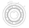
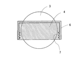
- FIG. 2 is a cross-sectional view taken along line AA in FIG. It is a perspective view of the separator which integrated the band used in the embodiment of FIG. It is a side view which shows the shape of the separator before unifying a metal band. It is a perspective view of other embodiment of the separator which integrated the metal band. It is sectional drawing of other embodiment of the separator which integrated the metal band. It is a side view which shows other embodiment of the separator before integrating a metal band. It is sectional drawing which shows 2nd Embodiment of the deep groove ball bearing to which this invention is applied.
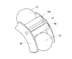
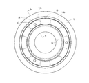
- FIG. 10 is a cross-sectional view taken along line AA in FIG. 9. It is a fragmentary perspective view which shows the relationship between the ball of the embodiment of FIG. 9, a separator, and a side plate. It is a perspective view of the 1st separator used for embodiment of FIG. It is a perspective view of the 2nd separator used for embodiment of FIG. It is a side view which shows 2nd Embodiment of the deep groove ball bearing to which a 2nd means is applied, and has shown the state which removed the shield board. It is a perspective view of the 1st separator used for embodiment of FIG.
- the deep groove ball bearing includes an inner ring 1, an outer ring 2, a plurality of balls 3 arranged between the inner ring 1 and the outer ring 2, and a plurality of separators 4 interposed between the plurality of balls 3 in the circumferential direction. I have.
- a raceway surface is formed on each of the outer peripheral surface of the inner ring 1 and the inner peripheral surface of the outer ring 2, and circumferential grooves that are recessed radially outward are formed on both shoulder portions of the inner peripheral surface of the outer ring 2. .
- the ball 3 is interposed between the raceway surfaces of the inner ring 1 and the outer ring 2.
- a shield plate 5 that shields the space between the inner ring 1 and the outer ring 2 is fitted into the circumferential grooves formed on both shoulders of the inner peripheral surface of the outer ring 2.
- the tip of the shield plate 5 is opposed to both shoulders of the outer peripheral surface of the inner ring 1 with a minute gap.
- the separator 4 has a substantially prismatic shape and is formed so that the circumferential length is shorter toward the inner diameter side, and the surface facing the outer ring is at least partially flat or polygonal in the circumferential direction. It is formed on the surface to facilitate attachment of the band 6.
- Reference numeral 4a in FIG. 4 indicates a flat surface.
- the separator 4 is formed of a solid lubricant, and the lubricant is transferred from the separator 4 to the rolling contact portion such as the surface of the ball 3 or the raceway surfaces of the inner ring 1 and the outer ring 2 by contact between the separator 4 and the ball 3 due to the rotation operation. Let each lubrication.
- Examples of the solid lubricant that forms the separator 4 include layered materials such as graphite, tungsten disulfide, and molybdenum disulfide, soft metal materials such as gold, silver, and lead, polymer resin materials such as PTFE and polyimide, and the like.
- a composite material having a main component can be used.
- a band 6 having a width smaller than the circumferential width of the separator 4 is integrally formed on at least one of the opposing surfaces of the inner and outer rings 1 and 2 except for the circumferential surface that contacts the ball 3.
- the band 6 is integrated except for the circumferential surface in contact with the ball 3 and the inner ring 1 facing surface.
- the material of the band 6 is more preferably made of stainless steel with good corrosion resistance or brass with good sliding properties.
- the width of the band is set such that the ball 3 does not fall off from the inner and outer rings 1 and 2 even when the separator 4 is worn.
- a ring 8 may be inserted between the separator 4 and the shield plate 5 for positioning the separator 4.
- This ring 8 is formed of a solid lubricant.
- the amount of lubricant supplied to the raceway surface is reduced when the width of the central portion of the strip 6 facing the outer raceway surface of the separator 4 is narrowed in the circumferential direction. Can be increased.
- the wear of the separator 4 is advanced by forming the shape of the part of the band 6 having a narrow width in the circumferential direction with a curved surface having a curvature larger than the curvature of the ball 3 to be used, the band 6 and the ball 3 The contact area with can be reduced.
- the movement restriction groove 9 (radial groove) of the band 6 is formed on at least one side surface of the separator 4 in the axial direction. May be provided.
- the separator 4 and the positioning ring 8 are preferably formed of graphite having particularly excellent lubricity among solid lubricants.
- the blending ratio of the graphite is 80 to 98 vol% for the separator 4, 95 to 100 vol% for the ring 8, and the specific wear amount of the separator 4 is 1.5 ⁇ 10 ⁇ 5 mm 3 / (N / m). Sufficient lubrication is performed, and when the bending strength is 4 MPa or more, the separator can be prevented from being damaged during operation.
- the clogging of the wear powder of the separator 4 inside the bearing does not cause a reduction in the bearing life. Can be. Further, if the bending strength of the separator 4 is too high, the separator 4 may be locked with the inner and outer rings when it is tilted during operation, and the bearing may be stopped. The upper limit of bending strength is set to 15 MPa so as not to occur.
- the separator 4 can be formed of a sintered body of graphite and a binder.
- the binder includes at least one metal selected from the group consisting of Fe, Cu, Ni, W, Sn, Co, and Cr, or at least one of oxides, nitrides, and borides of the respective metals. Use a good one.
- at least one of the separator 4 and the ring 8 can be formed by any one of a cold isostatic press molding method (CIP), an extrusion molding method, and a compression molding method.
- CIP cold isostatic press molding method
- the separator 4 and the ring 8 to be incorporated in the inside of the rolling bearing are formed of graphite, and the blending ratio of the graphite is 95 to 100 vol% for the ring 8 and 80 to 98 vol% for the separator 4, and the bending of the separator 4 is also performed.
- the strength to 4 to 15 MPa and the specific wear amount to 1.5 to 2.5 ⁇ 10 ⁇ 5 mm 3 / (N / m)
- the inside of the bearing is sufficiently lubricated, and the wear powder of the separator 4 during operation Can be prevented, and the separator 4 can be prevented from being damaged or locked. Therefore, the lubrication state between the transfer surfaces of the inner and outer rings and the rolling elements can be maintained well over a long period of time, and the bearing life can be extended.
- 9 to 13 show a first embodiment of a deep groove ball bearing to which the second means is applied.
- the deep groove ball bearing includes an inner ring 11, an outer ring 12, a plurality of balls 13 arranged between the inner ring 11 and the outer ring 12, and a plurality of separators 14 interposed between the plurality of balls 13 in the circumferential direction. I have.
- a raceway surface is formed on each of the outer peripheral surface of the inner ring 11 and the inner peripheral surface of the outer ring 12, and circumferential grooves that are recessed radially outward are formed on both shoulder portions of the inner peripheral surface of the outer ring 12. .
- the ball 13 is interposed between the raceway surfaces of the inner ring 11 and the outer ring 12.
- a shield plate 5 that shields the space between the inner ring 11 and the outer ring 12 is fitted into circumferential grooves formed on both shoulders of the inner peripheral surface of the outer ring 12.
- the tip of the shield plate 15 is opposed to both shoulders of the outer peripheral surface of the inner ring 11 via a minute gap.
- the separator 14 is composed of a first separator 14 a and a second separator 14 b in which a column member 17 to be described later is disposed in a set of two, and is adjacent in the circumferential direction in the facing space between the inner ring 11 and the outer ring 12.
- the ball 3 is interposed so as to partition the ball 3.
- An annular side plate 6 that prevents the first separator 14a and the second separator 14b from coming off in the axial direction is provided on both sides of the first separator 14a and the second separator 14b in the axial direction.
- the side plates 16 installed on both sides in the axial direction of the first separator 14a and the second separator 14b are connected by a column member 17 provided between the first separators 14a constituted by two. .
- three sets of first separators 14a are provided in the circumferential direction. Accordingly, the three pillar members 17 divide the first separator 14a and the second separator 14b arranged in the circumferential direction into three sets in the circumferential direction.
- the separator 14 is formed of a solid lubricant, and the lubricant is transferred from the separator 14 to a rolling contact portion such as the surface of the ball 13 or the races of the inner ring 11 and the outer ring 12 by contact between the separator 14 and the ball 13 accompanying the rotation operation. Each of them is lubricated.
- Examples of the solid lubricant that forms the separator 14 include layered materials such as graphite, tungsten disulfide, and molybdenum disulfide, soft metal materials such as gold, silver, and lead, polymer resin materials such as PTFE and polyimide, and the like.
- a composite material having a main component can be used.
- the separator 14 has a substantially prismatic shape, and is formed so that the circumferential length becomes shorter toward the inner diameter side.
- the surface where the separator 14 contacts the ball 13 is formed as a flat surface in the embodiment shown in FIGS. 9 to 13, but may be formed as a concave surface into which a part of the ball 13 fits.
- the surface on the outer ring 12 side of the separator 14 is formed in a convex arc surface.
- the radius of curvature of the convex arc surface is set smaller than the radius of curvature of the inner peripheral surface of the outer ring 12, but the radius of curvature of the convex arc surface is set larger than the radius of curvature of the inner peripheral surface of the outer ring 12. May be. Moreover, you may form the center part of a convex circular arc surface in a flat surface. Further, the surface on the inner ring side of the separator 14 is formed as a concave circular arc surface having a curvature similar to that of the outer peripheral surface of the inner ring 1 or a flat surface.
- the material of the side plate 16 can be formed of stainless steel such as SUS304 or brass, for example.
- the column member 17 for connecting the side plates 16 can be formed of stainless steel such as SUS304 or brass, for example.
- welding, caulking, a fitting type in which irregularities are provided on both parts, or the like can be employed.
- the column member 17 is formed in a cylindrical shape, but may be formed in a prism shape or a polygon having four or more corners.
- FIG. 14 shows a second embodiment of the second means.
- the first separator 14a formed in a pair is used as one member and shown in FIG.
- the through-hole 18 which penetrates the column member 17 is formed in the 1st separator 14a.
- the second separator 14 b has the same circumferential length as the first separator 14 a and does not have the through hole 18.
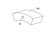
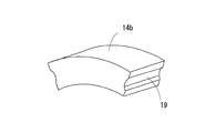
- FIGS. 17 and 18 are other examples of the separator 14 of the second means
- FIG. 17 is a first separator 14a having a through hole 18 through which the column member 17 is inserted, and both side surfaces in the circumferential direction.
- a guide groove 19 for guiding the ball 13 is provided.
- FIG. 18 shows a second separator 14b to be combined with the separator 14a of FIG. 17, and guide grooves 19 for guiding the balls 13 are provided on both side surfaces in the circumferential direction.
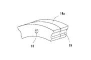
- FIG. 19 and 20 are other examples of the separator 14 of the second means
- FIG. 19 is a first separator 14a having a through hole 18 through which the column member 17 is inserted, and both side surfaces in the circumferential direction.
- a guide groove 19 for guiding the ball 13 is provided in the shaft and divided into two in the axial direction.
- FIG. 20 shows a second separator 14b that is combined with the separator 14a shown in FIG. 19, and is provided with guide grooves 19 for guiding the balls 13 on both side surfaces in the circumferential direction, and is divided into two in the axial direction.
Landscapes
- Engineering & Computer Science (AREA)
- General Engineering & Computer Science (AREA)
- Mechanical Engineering (AREA)
- Rolling Contact Bearings (AREA)
Abstract
セパレータの摩耗が進んでも、転動体の内外輪からの脱落を有効に防止することができる転がり軸受を提供することを課題とする。内外輪1,2間に複数の転動体3を配列し、転動体3間に角柱形状のセパレータ4を周方向に複数介装した転がり軸受において、前記セパレータ4の外面のうち、転動体3と接触する周方向の面を除く内外輪1,2の対向面、軸方向の側面の少なくとも一面に、セパレータ4の周方向の幅よりも幅の狭い帯金6を一体化し、セパレータ4のある程度以上の摩耗の進行を帯金6によって阻止するようにした。
Description
この発明は、内外輪間に複数の転動体を配列し、転動体間にセパレータを周方向に複数介装した転がり軸受、特に、フィルム延伸機のテンタクリップ用軸受等の高温雰囲気下、あるいは真空雰囲気下で使用するのに適した転がり軸受に関するものである。
フィルム延伸機のテンタクリップ用軸受は、一般的に150~250℃の高温雰囲気下で使用されるため、耐熱性が要求される。
特に、近年需要が高まっているPEEKやPI等の樹脂では400℃という超高温雰囲気下で延伸作業が行われている。
このような超高温雰囲気下で使用される転がり軸受では、400℃という高温で使用可能なグリースがないことから、転動体間に固体潤滑剤によって形成されたセパレータを介装させることにより、超高温下において徐々に潤滑剤を軌道面に供給するようにしている。
このようなセパレータを使用する転がり軸受は、特許文献1あるいは特許文献2に開示されている。
ところで、上記のような、転動体間にセパレータを周方向に複数介装した転がり軸受においては、セパレータの転動体との当接面が摩耗する。
特に、セパレータが固体潤滑剤によって形成されている場合には、セパレータの摩耗が激しい。
そして、セパレータの摩耗が進み、転動体の周方向に配列された転動体間の隙間を合算した総量が軸受の円周上の1/2以上に大きくなると、転動体が内外輪から脱落する懸念が生じる。
そこで、この発明は、セパレータの摩耗が進んでも、転動体の内外輪からの脱落を有効に防止することができる転がり軸受を提供しようとするものである。
前記の課題を解決するために、この発明は、内外輪間に複数の転動体を配列し、転動体間に角柱形状のセパレータを周方向に複数介装した転がり軸受において、前記セパレータの外面のうち、転動体と接触する周方向の面を除く内外輪の対向面の少なくとも一面に、セパレータの周方向の幅よりも幅の狭い帯金を一体化したことを特徴とする。
この発明の転がり軸受の代表例は、深溝玉軸受である。
前記帯金は、ステンレス鋼や黄銅、SS材にめっき処理を施したものを使用するが、滑り性や耐食性を考慮し、ステンレス鋼製や黄銅製がより好ましい。
前記セパレータは、グラファイト等の固体潤滑剤によって成形されている。
前記セパレータをグラファイトによって成形する場合、グラファイト配合率が80~98vol%のものが好ましい。
前記固体潤滑剤の曲げ強度は、4~15MPa、比摩耗量1.5~2.5×10⁻⁵mm3/(N/m)である。
前記帯金の幅は、前記セパレータが摩耗しても、玉が内外輪から脱落しない幅に設定する。
前記セパレータ側面の帯金の内面に、凹凸を設けることにより、セパレータと帯金との滑り止め効果が向上する。
前記セパレータは、周方向長さが内径側ほど短くなるように形成され、外輪と対向する面を、少なくとも一部平坦面又は周方向に多角形の面に形成することにより、帯金の取付けが容易になる。
帯金の周方向の移動を規制するために、前記セパレータの軸方向側面の少なくとも片面に帯金の移動規制用の溝(半径方向の溝)を設ける。
前記セパレータの外輪軌道面に対向する面の帯金軸方向長さの中央部を、周方向に幅を狭くすることにより、軌道面へ供給する潤滑剤量の増量化が図れる。
帯金の円周方向に幅を狭くした部位の形状は、使用する玉の曲率より大きい曲率の曲面で形成することにより、セパレータの摩耗が進んだ場合に、帯金と玉との接触面積を低減することができる。
前記転動体と接触するセパレータの周方向の面は、平坦面に形成することができる。
前記セパレータの位置決め用として、セパレータとシールド板間にリングを挿入する。このリングは固体潤滑剤によって形成されている。
前記位置決め用のリングは、グラファイト配合率95~100vol%のグラファイトを使用することが好ましい。
この発明の転がり軸受は、特に、テンタクリップ用の軸受として好適に使用することができる。
次に、前記の課題を解決するための第2の手段として、内外輪間に複数の転動体を配列し、転動体間にセパレータを周方向に複数介装した転がり軸受において、内外輪の軸方向両側面の内の少なくとも一方の面に、セパレータの軸方向の抜け出しを阻止する環状の側板を設け、この側板に、周方向に介装された複数のセパレータを周方向で複数組に区分けする柱部材を立設してもよい。
前記側板は、内外輪の軸方向両側面に設けることが好ましい。
前記側板の軸方向の外側面には、内外輪間をシールドするシールド板を配置する。
前記柱部材は、円柱形であっても、角柱形でもよい。
前記柱部材は、SUS304などのステンレス鋼や、黄銅によって形成することができる。錆などを考慮した場合、SUS304がより好ましく、転動体の摩耗や潤滑効果を考慮した場合、黄銅が好ましい。
前記柱部材は、セパレータとセパレータの間に配置しても、セパレータに柱部材に貫通孔を設け、貫通孔に柱部材を貫通させるようにしてもよい。
前記柱部材は、円柱形、4角形以上の多角柱形のいずれでもよい。
また、前記セパレータを軸方向に二分割し、転動体との当接面に転動体である玉の一部が嵌まる案内溝を形成するようにしてもよい。
この発明によると、セパレータの摩耗が進み、転動体が帯金に接触すると、セパレータの摩耗がそれ以上進まないため、転動体の内外輪からの脱落を防止することができる。また、たとえセパレータが摩滅しても帯金が転動体間に存在するため、転動体間のすきまを合算した総量が軸受の円周上1/2以下にすることができ、軸受の脱落を防止することができる。
そして、帯金を耐食性の良いステンレス鋼製や滑り性の良い黄銅製にすることにより、転動体が帯金に当たっても、滑りがよいため、転動体の損傷が少なく、長寿命の転がり軸受が得られる。
前記第2の手段によると、周方向に介装された複数のセパレータが、柱部材によって周方向に複数組に区分けされる。柱部材によって周方向に複数組に区分けされているので、セパレータの摩耗が進んでも、転動体全数が周方向の片側に偏ることがないため、転動体が軸受から脱落することがない。
以下、この発明の実施の形態について説明する。
図1~図4は、この発明を適用した深溝玉軸受の第1の実施形態を示している。
この深溝玉軸受は、内輪1と、外輪2と、内輪1と外輪2の間に配列される複数の玉3と、複数の玉3間に周方向に介装される複数のセパレータ4とを備えている。
この深溝玉軸受は、内輪1と、外輪2と、内輪1と外輪2の間に配列される複数の玉3と、複数の玉3間に周方向に介装される複数のセパレータ4とを備えている。
内輪1の外周面および外輪2の内周面には、軌道面がそれぞれ形成されており、外輪2の内周面両肩部には、径方向外向きに凹む周溝がそれぞれ形成されている。
玉3は、内輪1と外輪2の軌道面間に介装されている。
外輪2の内周面の両肩部に形成した周溝には、内輪1と外輪2の間の空間をシールドするシールド板5が嵌められている。シールド板5の先端は、内輪1の外周面の両肩部に対して微小隙間を介して対向させられている。
セパレータ4は、図4に示すように、ほぼ角柱形で、周方向長さが内径側ほど短くなるように形成され、外輪と対向する面を、少なくとも一部平坦面又は周方向に多角形の面に形成し、帯金6の取付けを容易にしている。図4の符号4aは、平坦面を示している。
セパレータ4は、固体潤滑剤により形成され、回転動作に伴うセパレータ4と玉3との接触によって潤滑剤をセパレータ4から玉3の表面や内輪1・外輪2の軌道面などの転がり接触部に転移させて、それぞれの潤滑を行わせている。
セパレータ4を形成する固体潤滑剤としては、例えば、グラファイトや二硫化タングステン、二硫化モリブデンなどの層状物質、金、銀、鉛などの軟質金属材、PTFEやポリイミドなどの高分子樹脂材やこれらを主成分とする複合材などを使用することができる。
セパレータ4には、外面のうち、玉3と接触する周方向の面を除く内外輪1,2の対向面の少なくとも一面に、セパレータ4の周方向の幅よりも幅の狭い帯金6を一体化しており、図1~図4に示す実施形態では、玉3と接触する周方向の面と内輪1対向面を除いて、帯金6を一体化している。
前記帯金6の材質としては、耐食性の良いステンレス鋼製や滑り性の良い黄銅がより好ましい。
前記帯金の幅は、前記セパレータ4が摩耗しても、玉3が内外輪1,2から脱落しない幅に設定する。
また、前記セパレータ4の位置決め用として、図8に示すように、セパレータ4とシールド板5間にリング8を挿入してもよい。このリング8は固体潤滑剤によって形成されている。
また、図5に示すように、前記セパレータ4の外輪軌道面に対向する面の帯金6の軸方向長さの中央部を、周方向に幅を狭くすると、軌道面へ供給する潤滑剤量の増量化を図ることができる。
帯金6の円周方向に幅を狭くした部位の形状は、使用する玉3の曲率より大きい曲率の曲面で形成することにより、セパレータ4の摩耗が進んだ場合に、帯金6と玉3との接触面積を低減することができる。
また、図6に示すように、セパレータ4の側面の帯金6の内面に、凹凸7を設けることにより、セパレータ4と帯金6との滑り止めを図ることができる。
また、図7に示すように、帯金6の周方向の移動を規制するために、前記セパレータ4の軸方向側面の少なくとも片面に帯金6の移動規制用の溝9(半径方向の溝)を設けてもよい。
前記セパレータ4と位置決め用のリング8は、それぞれ固体潤滑剤のうちでも特に潤滑性の優れたグラファイトで形成することが好ましい。そのグラファイトの配合率は、セパレータ4で80~98vol%、リング8で95~100vol%とし、セパレータ4の比摩耗量を1.5×10⁻⁵mm3/(N/m)とすることにより、十分な潤滑が行われ、曲げ強度を4MPa以上とすることにより、運転中のセパレータの破損を防止できる。
そして、セパレータ4の比摩耗量の上限を2.5×10⁻⁵mm3/(N/m)とすることにより、軸受内部でのセパレータ4の摩耗粉の詰まりが軸受寿命の短縮を引き起こさないようにすることができる。また、セパレータ4は、曲げ強度が高すぎると、運転中に傾いた姿勢になったときに内外輪との間でロックが生じ、軸受を停止させてしまうおそれがあるため、内外輪とのロックが生じないように曲げ強度の上限を15MPaとする。
また、前記セパレータ4は、グラファイトとバインダーとの焼結体で形成することができる。そのバインダーとしては、Fe、Cu、Ni、W、Sn、Co、Crの群から選択される少なくとも1種の金属または前記各金属の酸化物、窒化物、ホウ化物のうちの少なくとも一つを含むものを使用するとよい。また、セパレータ4とリング8の少なくとも一つは、冷間静水圧プレス成型法(CIP)、押し出し成型法、圧縮成型法のいずれかで成形することができる。
以上のように、転がり軸受の内部に組み込むセパレータ4とリング8をグラファイトで形成し、そのグラファイト配合率をリング8で95~100vol%、セパレータ4では80~98vol%にすると共に、セパレータ4の曲げ強度を4~15MPa、比摩耗量を1.5~2.5×10⁻⁵mm3/(N/m)とすることにより、軸受内部が十分に潤滑され、運転中にセパレータ4の摩耗粉が詰まったり、セパレータ4の破損やロックが生じたりすることを防止できる。したがって、内外輪の転送面と転動体との間の潤滑状態を長期間にわたって良好に維持でき、軸受寿命の延長を図ることができる。
図9~図13は、第2の手段を適用した深溝玉軸受の第1の実施形態を示している。
この深溝玉軸受は、内輪11と、外輪12と、内輪11と外輪12の間に配列される複数の玉13と、複数の玉13間に周方向に介装される複数のセパレータ14とを備えている。
内輪11の外周面および外輪12の内周面には、軌道面がそれぞれ形成されており、外輪12の内周面両肩部には、径方向外向きに凹む周溝がそれぞれ形成されている。
玉13は、内輪11と外輪12の軌道面間に介装されている。
外輪12の内周面の両肩部に形成した周溝には、内輪11と外輪12の間の空間をシールドするシールド板5が嵌められている。シールド板15の先端は、内輪11の外周面の両肩部に対して微小隙間を介して対向させられている。
セパレータ14は、2個1組で間に後述する柱部材17が配置される第1のセパレータ14aと、第2のセパレータ14bとからなり、内輪11と外輪12の対向空間において周方向で隣り合う玉3を仕切るように介装されている。
第1のセパレータ14aと、第2のセパレータ14bの軸方向の両側には、第1のセパレータ14aと第2のセパレータ14bの軸方向の抜け出しを阻止する環状の側板6が設置されている。
第1のセパレータ14aと第2のセパレータ14bの軸方向の両側に設置された側板16は、2個一組で構成される第1のセパレータ14a間に設けられた柱部材17によって連結されている。
図9~図13に示す実施形態では、第1のセパレータ14aを、周方向に三組設置している。したがって、三か所の柱部材17により、周方向に配置された第1のセパレータ14aと第2のセパレータ14bが、周方向に三組に区分けされる。
セパレータ14は、固体潤滑剤により形成され、回転動作に伴うセパレータ14と玉13との接触によって潤滑剤をセパレータ14から玉13の表面や内輪11・外輪12の軌道などの転がり接触部に転移させて、それぞれの潤滑を行わせている。
セパレータ14を形成する固体潤滑剤としては、例えば、グラファイトや二硫化タングステン、二硫化モリブデンなどの層状物質、金、銀、鉛などの軟質金属材、PTFEやポリイミドなどの高分子樹脂材やこれらを主成分とする複合材などを使用することができる。
セパレータ14は、ほぼ角柱形で、周方向長さが内径側ほど短くなるように形成されている。
セパレータ14が玉13と接触する面は、図9~図13に示す実施形態では、平坦面に形成しているが、玉13の一部が嵌まる凹面に形成してもよい。
セパレータ14の外輪12側の面は、凸状円弧面に形成されている。この凸状円弧面の曲率半径は、外輪12の内周面の曲率半径よりも小さく設定されているが、凸状円弧面の曲率半径を外輪12の内周面の曲率半径よりも大きく設定してもよい。また、凸状円弧面の中央部を、平坦面に形成してもよい。
また、セパレータ14の内輪側の面は、内輪1の外周面と同様の曲率を有する凹状円弧面、又は平坦面に形成されている。
また、セパレータ14の内輪側の面は、内輪1の外周面と同様の曲率を有する凹状円弧面、又は平坦面に形成されている。
上記側板16の材質は、例えば、SUS304等のステンレス鋼、あるいは黄銅によって形成することができる。
また、側板16を連結する柱部材17も、例えば、SUS304等のステンレス鋼、あるいは黄銅によって形成することができる。側板16と柱部材17とを連結する手段としては、溶接、かしめ、両部品に凹凸を設けたはめ込み式等を採用することができる。
柱部材17を黄銅によって形成した場合、セパレータ14が摩耗して、柱部材17と玉13とが接触しても、玉13の損傷を軽減することができる。
柱部材17は、図9~図13に示す実施形態では、円柱形に形成しているが、角柱形や4角以上の多角形に形成してもよい。
図14は、第2の手段の第2の実施形態であり、図9~図13に示す実施形態において、二個一組で形成した第1のセパレータ14aを一つの部材とし、図15に示すように、柱部材17を挿通する貫通孔18を第1のセパレータ14aに形成している。第2のセパレータ14bは、第1のセパレータ14aと同じ周方向長さを有し、貫通孔18を有しないものを使用している。
図17及び図18は、第2の手段のセパレータ14の他の例であり、図17は、柱部材17を挿通する貫通孔18を形成した第1のセパレータ14aであり、周方向の両側面に玉13を案内する案内溝19を設けている。図18は、図17のセパレータ14aと組合せる第2のセパレータ14bであり、周方向の両側面に玉13を案内する案内溝19を設けている。
図19及び図20は、第2の手段のセパレータ14の他の例であり、図19は、柱部材17を挿通する貫通孔18を形成した第1のセパレータ14aであり、周方向の両側面に玉13を案内する案内溝19を設け、軸方向に2分割されている。図20は、図19のセパレータ14aと組合せる第2のセパレータ14bであり、周方向の両側面に玉13を案内する案内溝19を設け、軸方向に2分割されている。
1 内輪
2 外輪
3 玉
4 セパレータ
4a 平坦面
5 シールド板
6 帯金
7 凹凸
8 リング
9 溝
2 外輪
3 玉
4 セパレータ
4a 平坦面
5 シールド板
6 帯金
7 凹凸
8 リング
9 溝
Claims (18)
- 内外輪間に複数の転動体を配列し、転動体間に角柱形状のセパレータを周方向に複数介装した転がり軸受において、前記セパレータの外面のうち、転動体と接触する周方向の面を除く内外輪の対向面の少なくとも一面に、セパレータの周方向の幅よりも幅の狭い帯金を一体化したことを特徴とする転がり軸受。
- 前記転動体が玉である請求項1に記載の転がり軸受。
- 前記帯金が、ステンレス鋼製または黄銅製である請求項1又は2に記載の転がり軸受。
- 前記セパレータが固体潤滑剤によって成形されている請求項1~3のいずれかに記載の転がり軸受。
- 前記固体潤滑剤がグラファイトからなる請求項4に記載の転がり軸受。
- 前記固体潤滑剤のグラファイト配合率が80~98vol%のものを使用した請求項5に記載の転がり軸受。
- 前記固体潤滑剤の曲げ強度が4~15MPa、比摩耗量1.5~2.5×10⁻⁵mm3/(N/m)である請求項4~6のいずれかに記載の転がり軸受。
- 前記帯金の幅が、前記セパレータが摩耗しても前記転動体が内外輪から脱落しない幅に設定されている請求項1~7のいずれかに記載の転がり軸受。
- 前記セパレータ側面の帯金の内面に、凹凸を設けている請求項1~8のいずれかに記載の転がり軸受。
- 前記セパレータは、周方向長さが内径側ほど短くなるように形成されている請求項1~9のいずれかに記載の転がり軸受。
- 前記セパレータの外輪と対向する面が、少なくとも一部平坦面又は周方向に多角形の面に形成されている請求項1~10のいずれかに記載の転がり軸受。
- 前記セパレータの軸方向側面の少なくとも片面に帯金の移動規制用の溝を設けた請求項1~11のいずれかに記載の転がり軸受。
- 前記セパレータの外輪軌道面に対向する面の帯金軸方向長さの中央部を、円周方向に幅を狭くした請求項1~12のいずれかに記載の転がり軸受。
- 帯金の円周方向に幅を狭くした部位の形状が、使用する転動体の曲率より大きい曲率の曲面で形成されている請求項13に記載の転がり軸受。
- 前記転動体と接触するセパレータの周方向の面が平坦面で形成されている請求項1~14のいずれかに記載の転がり軸受。
- 前記セパレータとシールド板間に固体潤滑剤によって形成された位置決め用のリングを挿入している請求項1~15のいずれかに記載の転がり軸受。
- 前記位置決め用のリングがグラファイト配合率95~100vol%のグラファイトからなる請求項16に記載の転がり軸受。
- テンタクリップ用の軸受として使用する請求項1~17のいずれかに記載の転がり軸受。
Priority Applications (3)
| Application Number | Priority Date | Filing Date | Title |
|---|---|---|---|
| US14/130,555 US9074630B2 (en) | 2011-07-07 | 2012-07-04 | Roller bearing |
| CN201280033420.9A CN103649573B (zh) | 2011-07-07 | 2012-07-04 | 滚动轴承 |
| EP12807717.9A EP2730792A1 (en) | 2011-07-07 | 2012-07-04 | Roller bearing |
Applications Claiming Priority (6)
| Application Number | Priority Date | Filing Date | Title |
|---|---|---|---|
| JP2011-151101 | 2011-07-07 | ||
| JP2011151101 | 2011-07-07 | ||
| JP2011-226117 | 2011-10-13 | ||
| JP2011226117A JP2013087797A (ja) | 2011-10-13 | 2011-10-13 | 転がり軸受 |
| JP2012-138597 | 2012-06-20 | ||
| JP2012138597A JP2013032838A (ja) | 2011-07-07 | 2012-06-20 | 転がり軸受 |
Publications (1)
| Publication Number | Publication Date |
|---|---|
| WO2013005771A1 true WO2013005771A1 (ja) | 2013-01-10 |
Family
ID=50253398
Family Applications (1)
| Application Number | Title | Priority Date | Filing Date |
|---|---|---|---|
| PCT/JP2012/067079 Ceased WO2013005771A1 (ja) | 2011-07-07 | 2012-07-04 | 転がり軸受 |
Country Status (4)
| Country | Link |
|---|---|
| US (1) | US9074630B2 (ja) |
| EP (1) | EP2730792A1 (ja) |
| CN (1) | CN103649573B (ja) |
| WO (1) | WO2013005771A1 (ja) |
Cited By (1)
| Publication number | Priority date | Publication date | Assignee | Title |
|---|---|---|---|---|
| US9303689B2 (en) | 2014-04-29 | 2016-04-05 | Roller Bearing Company Of America, Inc. | Non-rhythmically spaced rolling elements for reduction in bearing non-repeatable run-out |
Families Citing this family (1)
| Publication number | Priority date | Publication date | Assignee | Title |
|---|---|---|---|---|
| WO2015041212A1 (ja) | 2013-09-19 | 2015-03-26 | Ntn株式会社 | 固体潤滑転がり軸受 |
Citations (3)
| Publication number | Priority date | Publication date | Assignee | Title |
|---|---|---|---|---|
| JPS4941230B1 (ja) * | 1970-12-29 | 1974-11-07 | ||
| JPS63152023U (ja) * | 1987-03-26 | 1988-10-05 | ||
| JP2009030673A (ja) * | 2007-07-25 | 2009-02-12 | Hitachi Constr Mach Co Ltd | 建設機械の旋回軸受 |
Family Cites Families (12)
| Publication number | Priority date | Publication date | Assignee | Title |
|---|---|---|---|---|
| US1996841A (en) * | 1931-05-06 | 1935-04-09 | Gen Motors Corp | Separator |
| US2550912A (en) * | 1945-08-30 | 1951-05-01 | Acushnet Process Company | Antifriction bearing |
| US2897021A (en) * | 1958-02-13 | 1959-07-28 | Thew Shovel Co | Ball bearing |
| US3162493A (en) * | 1962-08-31 | 1964-12-22 | Ind Tectonics Inc | Reinforcing graphite and plastic separators by electroformed metallic shells |
| US3455616A (en) * | 1967-08-21 | 1969-07-15 | Kaydon Eng Corp | Ball bearing spacer |
| US3712694A (en) * | 1971-03-08 | 1973-01-23 | Garrett Corp | Antifriction bearing spacer |
| US3780606A (en) | 1972-05-15 | 1973-12-25 | Usm Corp | Hot log shear |
| JPS63152023A (ja) | 1986-12-16 | 1988-06-24 | Matsushita Electric Ind Co Ltd | 磁気記録媒体 |
| JP3934277B2 (ja) * | 1999-05-13 | 2007-06-20 | 株式会社ジェイテクト | 転がり軸受 |
| JP4269797B2 (ja) * | 2003-06-16 | 2009-05-27 | 株式会社ジェイテクト | 転がり軸受 |
| WO2007088750A1 (ja) * | 2006-01-31 | 2007-08-09 | Ntn Corporation | テンタークリップ用転がり軸受 |
| CN105003540B (zh) * | 2006-03-10 | 2018-07-27 | Ntn株式会社 | 衬垫 |
-
2012
- 2012-07-04 US US14/130,555 patent/US9074630B2/en not_active Expired - Fee Related
- 2012-07-04 CN CN201280033420.9A patent/CN103649573B/zh not_active Expired - Fee Related
- 2012-07-04 EP EP12807717.9A patent/EP2730792A1/en not_active Withdrawn
- 2012-07-04 WO PCT/JP2012/067079 patent/WO2013005771A1/ja not_active Ceased
Patent Citations (3)
| Publication number | Priority date | Publication date | Assignee | Title |
|---|---|---|---|---|
| JPS4941230B1 (ja) * | 1970-12-29 | 1974-11-07 | ||
| JPS63152023U (ja) * | 1987-03-26 | 1988-10-05 | ||
| JP2009030673A (ja) * | 2007-07-25 | 2009-02-12 | Hitachi Constr Mach Co Ltd | 建設機械の旋回軸受 |
Cited By (1)
| Publication number | Priority date | Publication date | Assignee | Title |
|---|---|---|---|---|
| US9303689B2 (en) | 2014-04-29 | 2016-04-05 | Roller Bearing Company Of America, Inc. | Non-rhythmically spaced rolling elements for reduction in bearing non-repeatable run-out |
Also Published As
| Publication number | Publication date |
|---|---|
| CN103649573A (zh) | 2014-03-19 |
| EP2730792A1 (en) | 2014-05-14 |
| US20140153854A1 (en) | 2014-06-05 |
| CN103649573B (zh) | 2016-05-11 |
| US9074630B2 (en) | 2015-07-07 |
Similar Documents
| Publication | Publication Date | Title |
|---|---|---|
| US10760616B2 (en) | Solid lubricant and solid-lubrication rolling bearing | |
| EP2711571A2 (en) | Rolling bearing with lubricant pockets in the raceway | |
| WO2013042579A1 (ja) | 固体潤滑転がり軸受 | |
| US9850948B2 (en) | Rolling bearing cage or cage element | |
| JP3934277B2 (ja) | 転がり軸受 | |
| CN202926884U (zh) | 固体润滑滚动轴承 | |
| WO2013005771A1 (ja) | 転がり軸受 | |
| JP2013032838A (ja) | 転がり軸受 | |
| US10663001B2 (en) | Ball bearing cage | |
| JP2013087797A (ja) | 転がり軸受 | |
| JP2018105506A (ja) | 固体潤滑転がり軸受 | |
| JP4269797B2 (ja) | 転がり軸受 | |
| JP2015059613A (ja) | 固体潤滑転がり軸受 | |
| JP2011231863A (ja) | 複列軸受用保持器および複列転がり軸受 | |
| JP6196514B2 (ja) | 固体潤滑転がり軸受 | |
| CN202851667U (zh) | 固体润滑滚动轴承 | |
| CN202926880U (zh) | 滚动轴承 | |
| US20180187722A1 (en) | Retainer and deep groove ball bearing | |
| JP6407551B2 (ja) | 固体潤滑転がり軸受 | |
| CN101133258A (zh) | 固体润滑滚子轴承 | |
| US9631672B2 (en) | Solid-lubrication rolling bearing | |
| JP6438546B2 (ja) | 固体潤滑転がり軸受 | |
| JP2006002818A (ja) | ころ軸受用合成樹脂保持器および円筒ころ軸受 | |
| JP2014066276A (ja) | 転がり軸受 | |
| JP2015224717A (ja) | 転がり軸受 |
Legal Events
| Date | Code | Title | Description |
|---|---|---|---|
| WWE | Wipo information: entry into national phase |
Ref document number: 201280033420.9 Country of ref document: CN |
|
| 121 | Ep: the epo has been informed by wipo that ep was designated in this application |
Ref document number: 12807717 Country of ref document: EP Kind code of ref document: A1 |
|
| WWE | Wipo information: entry into national phase |
Ref document number: 2012807717 Country of ref document: EP |
|
| WWE | Wipo information: entry into national phase |
Ref document number: 14130555 Country of ref document: US |
|
| NENP | Non-entry into the national phase |
Ref country code: DE |