WO2013008607A1 - 移動通信方法、移動通信システム及び無線基地局 - Google Patents
移動通信方法、移動通信システム及び無線基地局 Download PDFInfo
- Publication number
- WO2013008607A1 WO2013008607A1 PCT/JP2012/065973 JP2012065973W WO2013008607A1 WO 2013008607 A1 WO2013008607 A1 WO 2013008607A1 JP 2012065973 W JP2012065973 W JP 2012065973W WO 2013008607 A1 WO2013008607 A1 WO 2013008607A1
- Authority
- WO
- WIPO (PCT)
- Prior art keywords
- congestion
- bearer
- radio access
- eps
- core network
- Prior art date
- Legal status (The legal status is an assumption and is not a legal conclusion. Google has not performed a legal analysis and makes no representation as to the accuracy of the status listed.)
- Ceased
Links
Images





Classifications
-
- H—ELECTRICITY
- H04—ELECTRIC COMMUNICATION TECHNIQUE
- H04W—WIRELESS COMMUNICATION NETWORKS
- H04W28/00—Network traffic management; Network resource management
- H04W28/02—Traffic management, e.g. flow control or congestion control
- H04W28/0231—Traffic management, e.g. flow control or congestion control based on communication conditions
-
- H—ELECTRICITY
- H04—ELECTRIC COMMUNICATION TECHNIQUE
- H04W—WIRELESS COMMUNICATION NETWORKS
- H04W28/00—Network traffic management; Network resource management
- H04W28/02—Traffic management, e.g. flow control or congestion control
- H04W28/0252—Traffic management, e.g. flow control or congestion control per individual bearer or channel
-
- H—ELECTRICITY
- H04—ELECTRIC COMMUNICATION TECHNIQUE
- H04L—TRANSMISSION OF DIGITAL INFORMATION, e.g. TELEGRAPHIC COMMUNICATION
- H04L47/00—Traffic control in data switching networks
- H04L47/10—Flow control; Congestion control
- H04L47/25—Flow control; Congestion control with rate being modified by the source upon detecting a change of network conditions
Definitions
- the present invention relates to a mobile communication method, a mobile communication system, and a radio base station.
- the eNB radio base station
- the EPS-RAB Evolved Packet
- the flow rate of data in the System-Radio access Bearer is adjusted.
- 3GPP TS 23.401 3GPP TS 23.203
- the eNB when the eNB detects congestion, the eNB can adjust the flow rate of data in the EPS-RAB. There is a problem that the bandwidth of the core network bearer (S1 bearer or S5 bearer) corresponding to can not be adjusted.
- the present invention has been made in view of the above-described problems.
- congestion is detected in an eNB, the flow rate of data in the EPS-RAB and the bandwidth of the core network bearer corresponding to the EPS-RAB
- a first feature of the present invention is that a mobile station has a radio access bearer set up between the mobile station and a radio base station, and a core network bearer set up between the radio base station and a gateway device.
- Mobile communication method for transmitting and receiving data signals via the wireless base station when the wireless base station detects congestion, the mobile management node is notified of the reason for the congestion and the radio access bearer related to the congestion
- the gist is to have a process A for notifying identification information of each data flow flowing through the access bearer.
- the second feature of the present invention is that a mobile station has a radio access bearer set up between the mobile station and a radio base station, and a core network bearer set up between the radio base station and a gateway device.
- the mobile base station is configured to transmit and receive data signals via the wireless base station, and when the wireless base station detects congestion, the wireless management station notifies the mobility management node of the reason for the congestion and the wireless related to the congestion.
- the gist is that it is configured to notify identification information of an access bearer (further, each data flow or the like flowing through the radio access bearer).
- a third feature of the present invention is that a mobile station has a radio access bearer set up between the mobile station and a radio base station, and a core network bearer set up between the radio base station and a gateway device.
- the wireless base station in a mobile communication system configured to transmit and receive a data signal via the wireless communication station, when congestion is detected, the mobility management node and the wireless access related to the congestion when the congestion is detected.
- the gist of the present invention is to include a transmission unit configured to notify identification information of a bearer (further, each data flow or the like flowing in the radio access bearer).
- FIG. 1 is an overall configuration diagram of a mobile communication system according to a first embodiment of the present invention.
- FIG. 2 is a functional block diagram of the eNB according to the first embodiment of the present invention.
- FIG. 3 is a diagram for explaining the operation of the mobile communication system according to the first embodiment of the present invention.
- FIG. 4 is a diagram for explaining the operation of the mobile communication system according to the first embodiment of the present invention.
- FIG. 5 is a diagram for explaining the operation of the mobile communication system according to the first embodiment of the present invention.
- FIG. 6 is a diagram for explaining the operation of the mobile communication system according to the first modification of the present invention.
- FIG. 7 is a diagram for explaining the operation of the mobile communication system according to the first modification of the present invention.
- FIG. 8 is a diagram for explaining the operation of the mobile communication system according to the second modification of the present invention.
- FIG. 9 is a diagram for explaining the operation of the mobile communication system according to the second modification of the present invention.
- Mobile communication system according to the first embodiment of the present invention A mobile communication system according to a first embodiment of the present invention will be described with reference to FIG. 1 to FIG.
- the mobile communication system includes a PCRF (Policy and Charging Rules Function, policy and charging rule server device), an MME (Mobility Management Entity, a mobility management node), and a P-GW (Mobility Management Node).
- PCRF Policy and Charging Rules Function
- MME Mobility Management Entity
- P-GW Mobility Management Node
- PDN-Gateway PDN-Gateway
- S-GW Serving-Gateway
- the P-GW and S-GW can be connected via the S5 interface, and the S-GW and eNB # 1 to eNB # 3 can be connected via the S1 interface, and the MME and eNB # 1 to eNB # 3 can be connected via the S1-MME interface, the MME and S-GW can be connected via the S11 interface, and the PCRF and P-GW can be connected via the Gx interface. Can be connected.
- the PCRF and S-GW can be connected via the Gxc interface.
- an EPS-RAB can be set between the eNB # 1 to eNB # 3 and the UE, and an S1 bearer corresponding to the EPS-RAB is set between the eNB # 1 to eNB # 3 and the S-GW. Can be set, and an S5 bearer corresponding to the EPS-RAB / S1 bearer can be set between the S-GW and the P-GW.
- the P-GW can be connected to PDN (Packet Data Network, packet data network) # 1 / # 2.
- PDN Packet Data Network, packet data network
- the eNB includes a detection unit 11, an adjustment unit 12, and a transmission unit 13.
- the detection unit 11 is configured to detect congestion in the eNB.
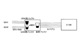
- the eNB is provided with a buffer for UE that is a buffer for each UE and a whole buffer that is a buffer for the entire eNB.
- the UE buffer is a buffer for accumulating signals transmitted / received by a specific UE, and the entire buffer is a fixed amount of buffer used when the buffer for the specific UE overflows.
- the UE bearer is set with “QCI (QoS Class ID)” indicating QoS (Quality of Service), and “Priority (priority)” and “Delay (allowable delay) are set based on the QCI. "Packet Loss Rate (allowable packet loss rate)” is determined, and the size and priority of the UE buffer corresponding to the UE bearer are determined.
- the detection unit 11 may use a buffer for a specific UE, a buffer usage for a specific UE exceeding a predetermined value, a buffer overflow, or a buffer usage rate. Is configured to detect congestion in the eNB when the value exceeds a predetermined value.
- the adjustment unit 12 is configured to adjust the flow rate of data in the E-RAB when the detection unit 11 detects congestion in the eNB. Specifically, the adjustment unit 12 is configured to reduce the flow rate of data in the E-RAB when the detection unit 11 detects congestion in the eNB.
- the adjustment unit 12 is configured to adjust the flow rate of data in the EPS-RAB of the UE.
- the adjustment unit 12 sets the EPS- of the UE using the entire buffer. It is configured to adjust the flow rate of data in the RAB.
- the adjustment unit 12 determines the EPS-RAB for adjusting the data flow rate based on the QCI of the EPS-RAB for each UE among the EPS-RABs of the UEs using the entire buffer. It may be configured.
- the transmission unit 13 is configured to transmit various signals to the UE, S-GW, MME, and the like.
- the transmission unit 13 provides the MME with the reason for the congestion (“Cause Value”) and the identification information (“bearer-ID” of the EPS-RAB related to the congestion). )).
- the transmission unit 13 may be configured to notify the identification information “data flow ID” of each data flow flowing in the EPS-RAB.
- the transmission unit 13 And the EPS-RAB identification information of the specific UE (that is, the EPS-RAB identification information adjusted by the adjustment unit 12).
- the transmission unit 13 may further be configured to notify the identification information “data flow ID” of each data flow flowing in the EPS-RAB.
- the transmission unit 13 When the detection unit 11 detects that the entire buffer overflows, or when the usage rate of the entire buffer exceeds a predetermined value, the transmission unit 13 notifies the reason for the congestion indicating that. , It is configured to notify the identification information of the EPS-RAB of the UE using the entire buffer (that is, the identification information of the EPS-RAB adjusted by the adjustment unit 12).
- the transmission unit 13 may further be configured to notify the identification information “data flow ID” of each data flow flowing in the EPS-RAB.
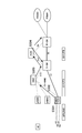
- step S102 when eNB # 1 detects congestion in the eNB by detecting buffer overflow in step S101, in step S102, it takes over the MME via the S1-MME interface. The congestion reason and the EPS-RAB identification information related to the congestion are notified.
- step S103 based on the notification, the MME transmits “Bearer Modification” instructing the S-GW to change the setting of the core network bearer corresponding to the EPS-RAB related to the congestion.
- the GW transmits “Bearer Modification” instructing the PCRF to change the setting of the core network bearer corresponding to the EPS-RAB related to the congestion.
- Update Bearer defined in TS23.401 of 3GPP may be used, or another message may be used.
- step S104 the PCRF transmits to the S-GW and P-GW “Bearer Modification” instructing to change the setting of the core network bearer corresponding to the EPS-RAB related to the congestion.
- the S-GW and the P-GW change the settings of the S1 bearer and the S5 bearer corresponding to the EPS-RAB related to the congestion according to the “Bearer Modification”.
- the S-GW and the P-GW reduce the bandwidth of the S1 bearer and the bandwidth of the S5 bearer corresponding to the EPS-RAB related to the congestion according to the “Bearer Modification”.
- the P-GW has a TDF (Traffic Detection Function), it performs DPI (Deep Packet Inspection) based on the EPS-RAB identification information notified by the above-mentioned “Bearer Modification”.
- the S-GW and the P-GW change the setting for each S1 bearer and S5 bearer corresponding to the EPS-RAB related to the congestion.
- the S-GW and the P-GW adjust (ie, reduce) the bandwidth in units of flows for the S1 bearer and the S5 bearer corresponding to the EPS-RAB related to the congestion.
- the S-GW and the P-GW do not reduce the bandwidth for the flow for emergency communication (for example, disaster communication) within the S1 bearer and the S5 bearer in which the same QCI is set, -For the flow for data communication (for example, game communication) of GBR (Guaranteed Bit Rate), it is possible to control in units of flow such as reducing the bandwidth.
- emergency communication for example, disaster communication
- GBR Guard Bit Rate
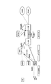
- eNB # 1 detects congestion in the eNB by detecting buffer overflow in step S201, it takes over the MME via the S1-MME interface in step S202. The congestion reason and the EPS-RAB identification information related to the congestion are notified.
- step S203 based on the notification, the MME transmits “Bearer Modification” instructing the S-GW to change the setting of the core network bearer corresponding to the EPS-RAB related to the congestion, and in step S204.
- step S205 the S-GW transmits “Bearer Modification” instructing the P-GW to change the setting of the core network bearer corresponding to the EPS-RAB related to the congestion.
- step S205 the P-GW , “Bearer Modification” is transmitted to the PCRF, which instructs to change the setting of the core network bearer corresponding to the EPS-RAB related to the congestion.
- step S206 the PCRF transmits “Bearer Modification” instructing the P-GW to change the setting of the core network bearer corresponding to the EPS-RAB related to the congestion.
- step S207 the P-GW , “Bearer Modification” instructing to change the setting of the core network bearer corresponding to the EPS-RAB related to the congestion is transmitted to the S-GW.
- the S-GW and the P-GW change the settings of the S1 bearer and the S5 bearer corresponding to the EPS-RAB related to the congestion according to the “Bearer Modification”.
- the S-GW and the P-GW reduce the bandwidth of the S1 bearer and the bandwidth of the S5 bearer corresponding to the EPS-RAB related to the congestion according to the “Bearer Modification”.
- DPI is performed based on the identification information of the EPS-RAB notified by the “Bearer Modification”, and the S-GW and the P-GW The setting is changed for each S1 bearer and S5 bearer corresponding to the EPS-RAB related to the congestion.
- the S-GW and the P-GW adjust (ie, reduce) the bandwidth in units of flows for the S1 bearer and the S5 bearer corresponding to the EPS-RAB related to the congestion.
- the S-GW and the P-GW may perform non-GBR data communication without reducing the bandwidth for the emergency communication flow in the S1 bearer and the S5 bearer in which the same QCI is set.
- the flow for use it is possible to control in units of flow such as reducing the bandwidth.
- the eNB when the eNB detects congestion, the eNB can notify the MME of the reason for the congestion and the identification information of the EPS-RAB related to the congestion. -Effective adjustment of resources can be realized by adjusting not only the data flow rate in the RAB but also the bandwidth of the core network bearer corresponding to the EPS-RAB.
- Modification 1 the mobile communication system according to the first modification of the present invention will be described with reference to FIG. 6 and FIG. 7 while focusing on differences from the mobile communication system according to the first embodiment described above.
- the eNB includes the above-described TDF and is configured to be able to perform DPI.
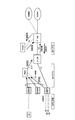
- eNB # 1 detects congestion in the eNB by detecting buffer overflow in step S301, DPI is performed, and the data flow rate in the EPS-RAB related to such congestion Determine the flow to be adjusted.
- step S302 the MME is notified of the reason for the congestion and the identification information of the flow in the EPS-RAB whose data flow rate should be adjusted via the S1-MME interface.
- step S303 based on the notification, the MME transmits “Bearer Modification” instructing the S-GW to change the flow setting in the core network bearer corresponding to the EPS-RAB related to the congestion.
- the S-GW transmits “Bearer Modification” instructing the PCRF to change the flow setting in the core network bearer corresponding to the EPS-RAB related to the congestion.
- step S304 the PCRF transmits, to the S-GW and P-GW, “Bearer Modification” instructing to change the flow setting in the core network bearer corresponding to the EPS-RAB related to the congestion.
- the S-GW and the P-GW change the settings of the flow in the S1 bearer and the flow in the S5 bearer corresponding to the EPS-RAB related to the congestion according to the “Bearer Modification”.
- the S-GW and the P-GW reduce the flow band in the S1 bearer and the flow band in the S5 bearer corresponding to the EPS-RAB related to the congestion according to the “Bearer Modification”. To do.
- the S-GW and the P-GW do not reduce the bandwidth for the flow for emergency communication (for example, disaster communication) within the S1 bearer and the S5 bearer in which the same QCI is set, -For the flow for data communication (for example, game communication) of GBR (Guaranteed Bit Rate), it is possible to control in units of flow such as reducing the bandwidth.
- emergency communication for example, disaster communication
- GBR Guard Bit Rate
- eNB # 1 detects congestion in the eNB by detecting buffer overflow in step S401, DPI is performed, and the data flow rate in the EPS-RAB related to such congestion Determine the flow to be adjusted.
- step S402 the eNB # 1 notifies the MME of the reason for the congestion and the flow identification information in the EPS-RAB related to the congestion via the S1-MME interface.
- step S403 based on the notification, the MME transmits “Bearer Modification” instructing the S-GW to change the flow setting in the core network bearer corresponding to the EPS-RAB related to the congestion.
- step S404 the S-GW transmits “Bearer Modification” instructing the P-GW to change the setting of the flow in the core network bearer corresponding to the EPS-RAB related to the congestion, and in step S405.
- the P-GW transmits “Bearer Modification” instructing the PCRF to change the flow setting in the core network bearer corresponding to the EPS-RAB related to the congestion.
- step S406 the PCRF transmits “Bearer Modification” instructing the P-GW to change the flow setting in the core network bearer corresponding to the EPS-RAB related to the congestion.
- step S407 the PCRF -GW transmits "Bearer Modification” which instruct
- the S-GW and the P-GW change the settings of the flow in the S1 bearer and the flow in the S5 bearer corresponding to the EPS-RAB related to the congestion according to the “Bearer Modification”.
- the S-GW and the P-GW reduce the flow band in the S1 bearer and the flow band in the S5 bearer corresponding to the EPS-RAB related to the congestion according to the “Bearer Modification”. To do.
- the S-GW and the P-GW may perform non-GBR data communication without reducing the bandwidth for the emergency communication flow in the S1 bearer and the S5 bearer in which the same QCI is set.
- the flow for use it is possible to control in units of flow such as reducing the bandwidth.
- the eNB when the eNB detects congestion, the eNB notifies the MME of the reason for the congestion and the flow identification information in the EPS-RAB related to the congestion. Therefore, effective utilization of resources can be realized by adjusting not only the flow rate of data in the flow in the EPS-RAB but also the bandwidth of the flow in the core network bearer corresponding to the EPS-RAB. .
- Modification 2 a mobile communication system according to Modification 2 of the present invention will be described with reference to FIG. 8 and FIG. 9 while focusing on differences from the mobile communication system according to the first embodiment described above.
- the plurality of eNB # 1 to eNB # 3 detect congestion by detecting buffer overflow in step S501, and in step S502, the eNB # 1 to eNB # 3 pass through the S1-MME interface to the MME.
- the reason for the congestion and the EPS-RAB identification information related to the congestion are notified.
- step S503 based on the notification, the MME transmits “Bearer Modification” instructing the S-GW to change the setting of the core network bearer corresponding to the EPS-RAB related to the congestion.
- the GW transmits “Bearer Modification” instructing the PCRF to change the setting of the core network bearer corresponding to the EPS-RAB related to the congestion.
- the MME is a special case such as the occurrence of a disaster because the plurality of eNB # 1 to eNB # 3 are notified of all EPS-RAB identification information as the EPS-RAB identification information related to congestion. Recognizing this, the bandwidth (resource) of all EPS-RABs is uniformly reduced, and the bandwidth (resource) of the core network bearer corresponding to all EPS-RABs is uniformly reduced with respect to the S-GW. “Bearer Modification” is transmitted to instruct.
- the S-GW transmits “Bearer Modification” instructing the PCRF to uniformly reduce the bandwidth (resource) of the core network bearer corresponding to all EPS-RABs.
- step S504 the PCRF transmits to the S-GW and P-GW “Bearer Modification” instructing to uniformly reduce the bandwidth of the core network bearer corresponding to all EPS-RABs.
- the S-GW and the P-GW uniformly reduce the bandwidth of the S1 bearer and the S5 bearer corresponding to all EPS-RABs in accordance with the “Bearer Modification”.
- the plurality of eNB # 1 to eNB # 3 detect congestion by detecting buffer overflow in step S601, and in step S602, the eNB # 1 to eNB # 3 pass through the S1-MME interface to the MME.
- the reason for the congestion and the EPS-RAB identification information related to the congestion are notified.
- step S603 based on the notification, the MME transmits “Bearer Modification” instructing the S-GW to change the setting of the core network bearer corresponding to the EPS-RAB related to the congestion, and in step S604.
- step S605 the S-GW transmits “Bearer Modification” instructing the P-GW to change the flow setting in the core network bearer corresponding to the EPS-RAB related to the congestion.
- -GW transmits "Bearer Modification” which instruct
- the MME is a special case such as the occurrence of a disaster because the plurality of eNB # 1 to eNB # 3 are notified of all EPS-RAB identification information as the EPS-RAB identification information related to congestion. (Each network operator decides and sets in advance, etc.) and all the EPS-RAB bandwidths (resources) are uniformly reduced, and all EPS-RABs are compared to S-GWs. "Bearer Modification" is transmitted to instruct to uniformly reduce the bandwidth (resource) of the core network bearer corresponding to
- the S-GW transmits “Bearer Modification” instructing the P-GW to uniformly reduce the bandwidth (resource) of the core network bearer corresponding to all EPS-RABs.
- the P-GW transmits “Bearer Modification” instructing the PCRF to uniformly reduce the bandwidth (resource) of the core network bearer corresponding to all EPS-RABs.
- step S606 the PCRF transmits a “Bearer Modification” instructing the P-GW to uniformly reduce the global area of the core network bearer corresponding to all EPS-RABs.
- step S607 the P-GW transmits the “Bearer Modification”.
- the GW transmits to the S-GW “Bearer Modification” instructing to uniformly reduce the global area of the core network bearer corresponding to all EPS-RABs.
- the S-GW and the P-GW uniformly reduce the bandwidth of the S1 bearer and the S5 bearer corresponding to all EPS-RABs in accordance with the “Bearer Modification”.
- the PCRF is responsible for all communication resources, that is, all EPS-
- the S1 bearer and S5 bearer bands (and all EPS-RAB bands) corresponding to the RAB are uniformly reduced.
- the resource allocation is reduced uniformly in all communications, and thus limited. By allocating resources evenly, as much communication as possible can be made possible.
- the first feature of the present embodiment is that an UE (mobile station) is configured between an UE and an eNB (radio base station), an EPS-RAB (radio access bearer), an eNB and an S-GW (gateway device). ) Is a mobile communication method for transmitting and receiving data signals via the S1 bearer (core network bearer) set between the eNB and the eNB when detecting congestion, the MME (mobile management node) The gist is to have a process A for notifying the reason for the congestion and the identification information of the EPS-RAB related to the congestion.
- the setting of the core network bearer corresponding to the EPS-RAB related to the congestion is set. Step B for instructing the change, and Step C for changing the setting of the core network bearer (S1 bearer) corresponding to the EPS-RAB related to the congestion when the S-GW receives the instruction May be.
- step C when the S-GW receives the above instruction, the S-GW changes the setting for each flow in the S1 bearer corresponding to the EPS-RAB related to the congestion. Also good.
- the method may further include a step of instructing to uniformly reduce the bandwidth of the core network bearer corresponding to all EPS-RABs.
- the second feature of the present embodiment is that the UE transmits and receives data signals via the EPS-RAB configured between the UE and the eNB and the S1 bearer configured between the eNB and the S-GW.
- the eNB detects congestion, the eNB is configured to notify the MME of the reason of the congestion and the identification information of the EPS-RAB related to the congestion. It is a summary.
- the MME when the MME receives the above-described reason for congestion and the identification information of the EPS-RAB related to the congestion, the MME sets the core network bearer corresponding to the EPS-RAB related to the congestion.
- the S-GW is configured to change the setting of the core network bearer (S1 bearer) corresponding to the EPS-RAB related to the congestion when the instruction is received. It may be.
- the S-GW is configured to change the setting in units of flows in the S1 bearer corresponding to the above-described congestion of EPS-RAB when receiving the above-described instruction. It may be.
- the EPS-RAB identification information related to the above-described congestion
- It may be configured to instruct to uniformly reduce the bandwidth of the core network bearer corresponding to the EPS-RAB.
- the third feature of the present embodiment is that the UE transmits and receives data signals via the EPS-RAB set between the UE and the eNB and the S1 bearer set between the eNB and the S-GW.
- An eNB in a mobile communication system configured to be configured to notify the MME of the reason for the congestion and the identification information of the EPS-RAB related to the congestion when the congestion is detected.
- the gist is that the transmitter 13 is provided.
- the transmission unit 11 may be configured to notify the identification information of the flow in the EPS-RAB related to the above-described congestion.
- the transmission unit 11 may be configured to notify a reason for congestion indicating that a specific mobile station buffer is congested.
- the transmission unit 11 may be configured to notify the reason for congestion indicating that the entire buffer is congested.
- Software modules include RAM (Random Access Memory), flash memory, ROM (Read Only Memory), EPROM (Erasable Programmable ROM), EEPROM (Electronically Erasable and Programmable, Removable ROM, and Hard Disk). Alternatively, it may be provided in an arbitrary format storage medium such as a CD-ROM.
- the storage medium is connected to the processor so that the processor can read and write information from and to the storage medium. Further, such a storage medium may be integrated in the processor. Such a storage medium and processor may be provided in the ASIC. Such an ASIC may be provided in a UE, eNB, MME, S-GW, P-GW, PCRF, or the like. Further, the storage medium and the processor may be provided in the UE, eNB, MME, S-GW, P-GW, PCRF, etc. as discrete components.
- the flow rate of data in the EPS-RAB and the bandwidth of the core network bearer corresponding to the EPS-RAB are also adjusted.
- UE ... mobile station eNB ... radio base station MME ... mobile management node S-GW ... serving gateway device P-GW ... packet data network gateway device PCRF ... policy and charging rule server device 11 ... detector 12 ... adjuster 13 ... transmitter
Landscapes
- Engineering & Computer Science (AREA)
- Computer Networks & Wireless Communication (AREA)
- Signal Processing (AREA)
- Mobile Radio Communication Systems (AREA)
Abstract
eNBにおける輻輳が検出された場合、EPS-RAB中のデータの流量だけではなく、かかるEPS-RABに対応するコアネットワークベアラの帯域についても調整することによって、リソースの有効活用を実現する。本実施形態に係る移動通信方法は、eNBが、輻輳を検出した場合、MMEに対して、かかる輻輳の理由及び輻輳に係るEPS-RABの識別情報を通知する工程Aを有する。
Description
本発明は、移動通信方法、移動通信システム及び無線基地局に関する。
従来の3GPPで規定されている移動通信システムでは、eNB(無線基地局)は、輻輳を検出した場合、UE(移動局)とeNBとの間の間で設定されているEPS-RAB(Evolved Packet System-Radio access Bearer)の中のデータの流量が調整されるように構成されている。
3GPP TS23.401
3GPP TS23.203
3GPP TS36.300
しかしながら、従来の3GPPで規定されている移動通信システムでは、上述したように、eNBは、輻輳を検出した場合、EPS-RABの中のデータの流量を調整することができるが、かかるEPS-RABに対応するコアネットワークベアラ(S1ベアラやS5ベアラ)の帯域を調整することができないという問題点があった。
そこで、本発明は、上述の課題に鑑みてなされたものであり、eNBにおける輻輳が検出された場合、EPS-RAB中のデータの流量、及び、かかるEPS-RABに対応するコアネットワークベアラの帯域についても調整することによって、リソースの有効活用を実現することができる移動通信方法、移動通信システム及び無線基地局を提供することを目的とする。
本発明の第1の特徴は、移動局が、該移動局と無線基地局との間で設定されている無線アクセスベアラ及び該無線基地局とゲートウェイ装置との間で設定されているコアネットワークベアラを介してデータ信号を送受信する移動通信方法であって、前記無線基地局が、輻輳を検出した場合、移動管理ノードに対して、該輻輳の理由及び該輻輳に係る無線アクセスベアラ(更に、無線アクセスベアラの中を流れる各データフロー等)の識別情報を通知する工程Aを有することを要旨とする。
本発明の第2の特徴は、移動局が、該移動局と無線基地局との間で設定されている無線アクセスベアラ及び該無線基地局とゲートウェイ装置との間で設定されているコアネットワークベアラを介してデータ信号を送受信するように構成されている移動通信システムであって、前記無線基地局は、輻輳を検出した場合、移動管理ノードに対して、該輻輳の理由及び該輻輳に係る無線アクセスベアラ(更に、無線アクセスベアラの中を流れる各データフロー等)の識別情報を通知するように構成されていることを要旨とする。
本発明の第3の特徴は、移動局が、該移動局と無線基地局との間で設定されている無線アクセスベアラ及び該無線基地局とゲートウェイ装置との間で設定されているコアネットワークベアラを介してデータ信号を送受信するように構成されている移動通信システムにおける該無線基地局であって、輻輳を検出した場合、移動管理ノードに対して、該輻輳の理由及び該輻輳に係る無線アクセスベアラ(更に、無線アクセスベアラの中を流れる各データフロー等)の識別情報を通知するように構成されている送信部を具備することを要旨とする。
(本発明の第1の実施形態に係る移動通信システム)
図1乃至図4を参照して、本発明の第1の実施形態に係る移動通信システムについて説明する。
図1乃至図4を参照して、本発明の第1の実施形態に係る移動通信システムについて説明する。
図1に示すように、本実施形態に係る移動通信システムは、PCRF(Policy and Charging Rules Function、ポリシー及び課金ルールサーバ装置)と、MME(Mobility Management Entity、移動管理ノード)と、P-GW(PDN-Gateway)と、S-GW(Serving-Gateway)と、eNB#1~eNB#3とを具備している。
ここで、P-GW及びS-GWは、S5インターフェイスを介して接続することができ、S-GW及びeNB#1~eNB#3は、S1インターフェイスを介して接続することができ、MME及びeNB#1~eNB#3は、S1-MMEインターフェイスを介して接続することができ、MME及びS-GWは、S11インターフェイスを介して接続することができ、PCRF及びP-GWは、Gxインターフェイスを介して接続することができる。
なお、S5インターフェイスにおいてPMIP(Proxy Mobile IP)が適用されている場合には、PCRF及びS-GWは、Gxcインターフェイスを介して接続することができる。
すなわち、eNB#1~eNB#3とUEとの間では、EPS-RABが設定可能であり、eNB#1~eNB#3とS-GWとの間では、かかるEPS-RABに対応するS1ベアラが設定可能であり、S-GWとP-GWとの間では、かかるEPS-RAB/S1ベアラに対応するS5ベアラが設定可能である。
また、P-GWは、PDN(Packet Data Network、パケットデータネットワーク)#1/#2に接続することができる。
図2に示すように、eNBは、検出部11と、調整部12と、送信部13とを具備している。
検出部11は、eNBにおける輻輳を検出するように構成されている。
ここで、eNBには、図3に示すように、UE毎のバッファであるUE用のバッファ及びeNB全体のバッファである全体バッファが設けられている。
UE用のバッファは、特定のUEによって送受信される信号を蓄積するためのバッファであり、全体バッファは、特定のUE用のバッファが溢れた場合に用いられる一定量のバッファである。
なお、UE用のベアラには、QoS(Quality of Service)を示す「QCI(QoS Class ID)」が設定されており、かかるQCIに基づいて「Priority(優先度)」や「Delay(許容遅延)」や「Packet Loss Rate(許容パケット損失レート)」が決められており、かかるUE用のベアラに対応するUE用のバッファのサイズや優先度が決められている。
例えば、検出部11は、特定のUE用のバッファが溢れた場合や、特定のUE用のバッファの使用率が所定値を超えた場合や、全体バッファが溢れた場合や、全体バッファの使用率が所定値を超えた場合等に、eNBにおける輻輳を検出するように構成されている。
調整部12は、検出部11によってeNBにおける輻輳が検出された場合、E-RAB中のデータの流量を調整するように構成されている。具体的には、調整部12は、検出部11によってeNBにおける輻輳が検出された場合、E-RAB中のデータの流量を小さくするように構成されている。
ここで、検出部11が、特定のUE用のバッファが溢れたことを検出した場合や、特定のUE用のバッファの使用率が所定値を超えた場合等に、調整部12は、かかる特定のUEのEPS-RAB中のデータの流量を調整するように構成されている。
また、検出部11が、全体バッファが溢れたことを検出した場合や、全体バッファの使用率が所定値を超えた場合等に、調整部12は、全体バッファを利用しているUEのEPS-RAB中のデータの流量を調整するように構成されている。
かかる場合、調整部12は、全体バッファを利用しているUEのEPS-RABのうち、各UE用のEPS-RABのQCIに基づいて、データの流量を調整するEPS-RABを決定するように構成されていてもよい。
送信部13は、UEやS-GWやMME等に対して各種信号を送信するように構成されている。
例えば、送信部13は、検出部11によってeNBにおける輻輳が検出された場合、MMEに対して、かかる輻輳の理由(「Cause Value」)及び輻輳に係るEPS-RABの識別情報(「bearer-ID」)を通知するように構成されている。
ここで、送信部13は、EPS-RABの中を流れる各データフローの識別情報「データフローID」)を通知するように構成されていてもよい。
ここで、検出部11が、特定のUE用のバッファが溢れたことを検出した場合や、特定のUE用のバッファの使用率が所定値を超えた場合等に、送信部13は、その旨を示す輻輳の理由を通知すると共に、かかる特定のUEのEPS-RABの識別情報(すなわち、調整部12によって調整されたEPS-RABの識別情報)を通知するように構成されている。
なお、かかる場合、送信部13は、更に、EPS-RABの中を流れる各データフローの識別情報「データフローID」)を通知するように構成されていてもよい。
また、検出部11が、全体バッファが溢れたことを検出した場合や、全体バッファの使用率が所定値を超えた場合等に、送信部13は、その旨を示す輻輳の理由を通知すると共に、全体バッファを利用しているUEのEPS-RABの識別情報(すなわち、調整部12によって調整されたEPS-RABの識別情報)を通知するように構成されている。
なお、かかる場合、送信部13は、更に、EPS-RABの中を流れる各データフローの識別情報「データフローID」)を通知するように構成されていてもよい。
以下、図4及び図5を参照して、本実施形態に係る移動通信システムの動作の一例について説明する。
第1に、図4を参照して、S5インターフェイスにおいてPMIPが適用されている場合の動作について説明する。
図4に示すように、eNB#1が、ステップS101において、バッファ溢れを検出することによって、eNBにおける輻輳を検出した場合、ステップS102において、MMEに対して、S1-MMEインターフェイスを介して、かかる輻輳の理由及び輻輳に係るEPS-RABの識別情報を通知する。
ステップS103において、MMEは、かかる通知に基づいて、S-GWに対して、かかる輻輳に係るEPS-RABに対応するコアネットワークベアラの設定の変更を指示する「Bearer Modification」を送信し、S-GWは、PCRFに対して、かかる輻輳に係るEPS-RABに対応するコアネットワークベアラの設定の変更を指示する「Bearer Modification」を送信する。
ここで、「Bearer Modification」の代わりに、3GPPのTS23.401に規定されている「Update Bearer」が用いられてもよいし、他のメッセージが用いられてもよい。
ステップS104において、PCRFは、S-GW及びP-GWに対して、かかる輻輳に係るEPS-RABに対応するコアネットワークベアラの設定の変更を指示する「Bearer Modification」を送信する。
ここで、S-GW及びP-GWは、かかる「Bearer Modification」に応じて、かかる輻輳に係るEPS-RABに対応するS1ベアラ及びS5ベアラの設定を変更する。
具体的には、S-GW及びP-GWは、かかる「Bearer Modification」に応じて、かかる輻輳に係るEPS-RABに対応するS1ベアラの帯域及びS5ベアラの帯域を小さくする。
なお、P-GWが、TDF(Traffic Detection Function)を具備している場合、上述の「Bearer Modification」によって通知されたEPS-RABの識別情報に基づいて、DPI(Deep Packet Inspection)を実施し、S-GW及びP-GWは、かかる輻輳に係るEPS-RABに対応するS1ベアラ及びS5ベアラについてフロー単位で設定を変更する。
すなわち、かかる場合、S-GW及びP-GWは、かかる輻輳に係るEPS-RABに対応するS1ベアラ及びS5ベアラについてフロー単位で帯域を調整する(すなわち、小さくする)。
例えば、かかる場合、S-GW及びP-GWは、同一のQCIが設定されているS1ベアラ及びS5ベアラ内で、緊急通信(例えば、災害通信)用のフローについては帯域を減らさずに、non-GBR(Guaranteed Bit Rate)のデータ通信(例えば、ゲーム通信)用のフローについては帯域を小さくするといったフロー単位の制御を行うことができる。
第2に、図5を参照して、S5インターフェイスにおいてGTP(GPRS Tunneling Protocol)が適用されている場合の動作について説明する。
図5に示すように、eNB#1が、ステップS201において、バッファ溢れを検出することによって、eNBにおける輻輳を検出した場合、ステップS202において、MMEに対して、S1-MMEインターフェイスを介して、かかる輻輳の理由及び輻輳に係るEPS-RABの識別情報を通知する。
ステップS203において、MMEは、かかる通知に基づいて、S-GWに対して、かかる輻輳に係るEPS-RABに対応するコアネットワークベアラの設定の変更を指示する「Bearer Modification」を送信し、ステップS204において、S-GWは、P-GWに対して、かかる輻輳に係るEPS-RABに対応するコアネットワークベアラの設定の変更を指示する「Bearer Modification」を送信し、ステップS205において、P-GWは、PCRFに対して、かかる輻輳に係るEPS-RABに対応するコアネットワークベアラの設定の変更を指示する「Bearer Modification」を送信する。
ステップS206において、PCRFは、P-GWに対して、かかる輻輳に係るEPS-RABに対応するコアネットワークベアラの設定の変更を指示する「Bearer Modification」を送信し、ステップS207において、P-GWは、S-GWに対して、かかる輻輳に係るEPS-RABに対応するコアネットワークベアラの設定の変更を指示する「Bearer Modification」を送信する。
ここで、S-GW及びP-GWは、かかる「Bearer Modification」に応じて、かかる輻輳に係るEPS-RABに対応するS1ベアラ及びS5ベアラの設定を変更する。
具体的には、S-GW及びP-GWは、かかる「Bearer Modification」に応じて、かかる輻輳に係るEPS-RABに対応するS1ベアラの帯域及びS5ベアラの帯域を小さくする。
なお、P-GWが、TDFを具備している場合、上述の「Bearer Modification」によって通知されたEPS-RABの識別情報に基づいて、DPIを実施し、S-GW及びP-GWは、かかる輻輳に係るEPS-RABに対応するS1ベアラ及びS5ベアラについてフロー単位で設定を変更する。
すなわち、かかる場合、S-GW及びP-GWは、かかる輻輳に係るEPS-RABに対応するS1ベアラ及びS5ベアラについてフロー単位で帯域を調整する(すなわち、小さくする)。
例えば、かかる場合、S-GW及びP-GWは、同一のQCIが設定されているS1ベアラ及びS5ベアラ内で、緊急通信用のフローについては帯域を小さくせずに、non-GBRのデータ通信用のフローについては帯域を小さくするといったフロー単位の制御を行うことができる。
本実施形態に係る移動通信システムによれば、eNBが、輻輳を検出した場合に、MMEに対して、かかる輻輳の理由及び輻輳に係るEPS-RABの識別情報を通知することができるため、EPS-RAB中のデータの流量だけではなく、かかるEPS-RABに対応するコアネットワークベアラの帯域についても調整することによって、リソースの有効活用を実現することができる。
(変更例1)
以下、図6及び図7を参照して、本発明の変更例1に係る移動通信システムについて、上述の第1の実施形態に係る移動通信システムとの相違点に着目して説明する。
以下、図6及び図7を参照して、本発明の変更例1に係る移動通信システムについて、上述の第1の実施形態に係る移動通信システムとの相違点に着目して説明する。
本変更例1に係る移動通信システムでは、P-GWではなく、eNBが、上述のTDFを具備しており、DPIを実施することができるように構成されている。
第1に、図6を参照して、S5インターフェイスにおいてPMIPが適用されている場合の動作について説明する。
図6に示すように、eNB#1が、ステップS301において、バッファ溢れを検出することによって、eNBにおける輻輳を検出した場合、DPIを実施し、かかる輻輳に係るEPS-RAB内で、データの流量を調整すべきフローを決定する。
ステップS302において、MMEに対して、S1-MMEインターフェイスを介して、かかる輻輳の理由及びデータの流量を調整すべきEPS-RAB内のフローの識別情報を通知する。
ステップS303において、MMEは、かかる通知に基づいて、S-GWに対して、かかる輻輳に係るEPS-RABに対応するコアネットワークベアラ内のフローの設定の変更を指示する「Bearer Modification」を送信し、S-GWは、PCRFに対して、かかる輻輳に係るEPS-RABに対応するコアネットワークベアラ内のフローの設定の変更を指示する「Bearer Modification」を送信する。
ステップS304において、PCRFは、S-GW及びP-GWに対して、かかる輻輳に係るEPS-RABに対応するコアネットワークベアラ内のフローの設定の変更を指示する「Bearer Modification」を送信する。
ここで、S-GW及びP-GWは、かかる「Bearer Modification」に応じて、かかる輻輳に係るEPS-RABに対応するS1ベアラ内のフロー及びS5ベアラ内のフローの設定を変更する。
具体的には、S-GW及びP-GWは、かかる「Bearer Modification」に応じて、かかる輻輳に係るEPS-RABに対応するS1ベアラ内のフローの帯域及びS5ベアラ内のフローの帯域を小さくする。
例えば、かかる場合、S-GW及びP-GWは、同一のQCIが設定されているS1ベアラ及びS5ベアラ内で、緊急通信(例えば、災害通信)用のフローについては帯域を減らさずに、non-GBR(Guaranteed Bit Rate)のデータ通信(例えば、ゲーム通信)用のフローについては帯域を小さくするといったフロー単位の制御を行うことができる。
第2に、図7を参照して、S5インターフェイスにおいてGTPが適用されている場合の動作について説明する。
図7に示すように、eNB#1が、ステップS401において、バッファ溢れを検出することによって、eNBにおける輻輳を検出した場合、DPIを実施し、かかる輻輳に係るEPS-RAB内で、データの流量を調整すべきフローを決定する。
ステップS402において、eNB#1は、MMEに対して、S1-MMEインターフェイスを介して、かかる輻輳の理由及び輻輳に係るEPS-RAB内のフローの識別情報を通知する。
ステップS403において、MMEは、かかる通知に基づいて、S-GWに対して、かかる輻輳に係るEPS-RABに対応するコアネットワークベアラ内のフローの設定の変更を指示する「Bearer Modification」を送信し、ステップS404において、S-GWは、P-GWに対して、かかる輻輳に係るEPS-RABに対応するコアネットワークベアラ内のフローの設定の変更を指示する「Bearer Modification」を送信し、ステップS405において、P-GWは、PCRFに対して、かかる輻輳に係るEPS-RABに対応するコアネットワークベアラ内のフローの設定の変更を指示する「Bearer Modification」を送信する。
ステップS406において、PCRFは、P-GWに対して、かかる輻輳に係るEPS-RABに対応するコアネットワークベアラ内のフローの設定の変更を指示する「Bearer Modification」を送信し、ステップS407において、P-GWは、S-GWに対して、かかる輻輳に係るEPS-RABに対応するコアネットワークベアラ内のフローの設定の変更を指示する「Bearer Modification」を送信する。
ここで、S-GW及びP-GWは、かかる「Bearer Modification」に応じて、かかる輻輳に係るEPS-RABに対応するS1ベアラ内のフロー及びS5ベアラ内のフローの設定を変更する。
具体的には、S-GW及びP-GWは、かかる「Bearer Modification」に応じて、かかる輻輳に係るEPS-RABに対応するS1ベアラ内のフローの帯域及びS5ベアラ内のフローの帯域を小さくする。
例えば、かかる場合、S-GW及びP-GWは、同一のQCIが設定されているS1ベアラ及びS5ベアラ内で、緊急通信用のフローについては帯域を小さくせずに、non-GBRのデータ通信用のフローについては帯域を小さくするといったフロー単位の制御を行うことができる。
本変更例1に係る移動通信システムによれば、eNBが、輻輳を検出した場合に、MMEに対して、かかる輻輳の理由及び輻輳に係るEPS-RAB内のフローの識別情報を通知することができるため、EPS-RAB内のフロー中のデータの流量だけではなく、かかるEPS-RABに対応するコアネットワークベアラ内のフローの帯域についても調整することによって、リソースの有効活用を実現することができる。
(変更例2)
以下、図8及び図9を参照して、本発明の変更例2に係る移動通信システムについて、上述の第1の実施形態に係る移動通信システムとの相違点に着目して説明する。
以下、図8及び図9を参照して、本発明の変更例2に係る移動通信システムについて、上述の第1の実施形態に係る移動通信システムとの相違点に着目して説明する。
第1に、図8を参照して、災害発生等のような特別なケース(ネットワークの運用事業者が事前に決め設定しておく等)において、S5インターフェイスにおいてPMIPが適用されている場合の動作について説明する。
図8に示すように、複数のeNB#1~eNB#3は、ステップS501において、バッファ溢れを検出することによって、輻輳を検出し、ステップS502において、MMEに対して、S1-MMEインターフェイスを介して、かかる輻輳の理由及び輻輳に係るEPS-RABの識別情報(本事変更例2では、全てのEPS-RABの識別情報)を通知する。
ステップS503において、MMEは、かかる通知に基づいて、S-GWに対して、かかる輻輳に係るEPS-RABに対応するコアネットワークベアラの設定の変更を指示する「Bearer Modification」を送信し、S-GWは、PCRFに対して、かかる輻輳に係るEPS-RABに対応するコアネットワークベアラの設定の変更を指示する「Bearer Modification」を送信する。
ここで、MMEは、複数のeNB#1~eNB#3から、輻輳に係るEPS-RABの識別情報として、全てのEPS-RABの識別情報が通知されたため、災害発生等の特別なケースであることを認識し、全てのEPS-RABの帯域(リソース)を一律に小さくすると共に、S-GWに対して、全てのEPS-RABに対応するコアネットワークベアラの帯域(リソース)を一律に小さくするように指示する「Bearer Modification」を送信する。
同様に、S-GWは、PCRFに対して、全てのEPS-RABに対応するコアネットワークベアラの帯域(リソース)を一律に小さくするように指示する「Bearer Modification」を送信する。
ステップS504において、PCRFは、S-GW及びP-GWに対して、全てのEPS-RABに対応するコアネットワークベアラの帯域を一律に小さくするように指示する「Bearer Modification」を送信する。
ここで、S-GW及びP-GWは、かかる「Bearer Modification」に応じて、全てのEPS-RABに対応するS1ベアラ及びS5ベアラの帯域を一律に小さくする。
第2に、図9を参照して、災害発生等のような特別なケースにおいて、S5インターフェイスにおいてGTPが適用されている場合の動作について説明する。
図9に示すように、複数のeNB#1~eNB#3は、ステップS601において、バッファ溢れを検出することによって、輻輳を検出し、ステップS602において、MMEに対して、S1-MMEインターフェイスを介して、かかる輻輳の理由及び輻輳に係るEPS-RABの識別情報(本事変更例2では、全てのEPS-RABの識別情報)を通知する。
ステップS603において、MMEは、かかる通知に基づいて、S-GWに対して、かかる輻輳に係るEPS-RABに対応するコアネットワークベアラの設定の変更を指示する「Bearer Modification」を送信し、ステップS604において、S-GWは、P-GWに対して、かかる輻輳に係るEPS-RABに対応するコアネットワークベアラ内のフローの設定の変更を指示する「Bearer Modification」を送信し、ステップS605において、P-GWは、PCRFに対して、かかる輻輳に係るEPS-RABに対応するコアネットワークベアラ内のフローの設定の変更を指示する「Bearer Modification」を送信する。
ここで、MMEは、複数のeNB#1~eNB#3から、輻輳に係るEPS-RABの識別情報として、全てのEPS-RABの識別情報が通知されたため、災害発生等の特別なケースであることを認識し(ネットワークの運用事業者が事前に決め設定しておく等)、全てのEPS-RABの帯域(リソース)を一律に小さくすると共に、S-GWに対して、全てのEPS-RABに対応するコアネットワークベアラの帯域(リソース)を一律に小さくするように指示する「Bearer Modification」を送信する。
同様に、S-GWは、P-GWに対して、全てのEPS-RABに対応するコアネットワークベアラの帯域(リソース)を一律に小さくするように指示する「Bearer Modification」を送信する。
さらに、P-GWは、PCRFに対して、全てのEPS-RABに対応するコアネットワークベアラの帯域(リソース)を一律に小さくするように指示する「Bearer Modification」を送信する。
ステップS606において、PCRFは、P-GWに対して、全てのEPS-RABに対応するコアネットワークベアラの大域を一律に小さくするように指示する「Bearer Modification」を送信し、ステップS607において、P-GWは、S-GWに対して、全てのEPS-RABに対応するコアネットワークベアラの大域を一律に小さくするように指示する「Bearer Modification」を送信する。
ここで、S-GW及びP-GWは、かかる「Bearer Modification」に応じて、全てのEPS-RABに対応するS1ベアラ及びS5ベアラの帯域を一律に小さくする。
なお、P-GWに対して、所定閾値以上の着信があった場合には、同様に、災害発生等のような特別なケースとして、PCRFは、全ての通信におけるリソース、すなわち、全てのEPS-RABに対応するS1ベアラ及びS5ベアラの帯域(及び、全てのEPS-RABの帯域)を一律に小さくする。
本変更例2に係る移動通信システムによれば、災害発生等の特別なケースにおいてネットワークの運用事業者が事前に設定した基準に従い、全ての通信において一律にリソース割当を減らすことによって、限られたリソースを均等に割り当てることにより出来るだけ多くの通信を可能にすることができる。
以上に述べた本実施形態の特徴は、以下のように表現されていてもよい。
本実施形態の第1の特徴は、UE(移動局)が、UEとeNB(無線基地局)との間で設定されているEPS-RAB(無線アクセスベアラ)及びeNBとS-GW(ゲートウェイ装置)との間で設定されているS1ベアラ(コアネットワークベアラ)を介してデータ信号を送受信する移動通信方法であって、eNBが、輻輳を検出した場合、MME(移動管理ノード)に対して、かかる輻輳の理由及び輻輳に係るEPS-RABの識別情報を通知する工程Aを有することを要旨とする。
本実施形態の第1の特徴において、MMEが、上述の輻輳の理由及び輻輳に係るEPS-RABの識別情報を受信した場合に、かかる輻輳に係るEPS-RABに対応するコアネットワークベアラの設定の変更を指示する工程Bと、S-GWが、かかる指示を受信した場合に、かかる輻輳に係るEPS-RABに対応するコアネットワークベアラ(S1ベアラ)の設定を変更する工程Cとを更に有してもよい。
本実施形態の第1の特徴において、工程Cにおいて、S-GWは、上述の指示を受信した場合に、かかる輻輳に係るEPS-RABに対応するS1ベアラ内のフロー単位で設定を変更してもよい。
本実施形態の第1の特徴において、MMEが、複数のeNB#1~eNB#3から、上述の輻輳に係るEPS-RABの識別情報として、全てのEPS-RABの識別情報が通知された場合、全てのEPS-RABに対応するコアネットワークベアラの帯域を一律に小さくするように指示する工程を更に有してもよい。
本実施形態の第2の特徴は、UEが、UEとeNBとの間で設定されているEPS-RAB及びeNBとS-GWとの間で設定されているS1ベアラを介してデータ信号を送受信するように構成されている移動通信システムであって、eNBは、輻輳を検出した場合、MMEに対して、かかる輻輳の理由及び輻輳に係るEPS-RABの識別情報を通知するように構成されていることを要旨とする。
本実施形態の第2の特徴において、MMEは、上述の輻輳の理由及び輻輳に係るEPS-RABの識別情報を受信した場合に、かかる輻輳に係るEPS-RABに対応するコアネットワークベアラの設定の変更を指示するように構成されており、S-GWは、かかる指示を受信した場合に、かかる輻輳に係るEPS-RABに対応するコアネットワークベアラ(S1ベアラ)の設定を変更するように構成されていてもよい。
本実施形態の第2の特徴において、S-GWは、上述の指示を受信した場合に、上述の輻輳に係るEPS-RABに対応するS1ベアラ内のフロー単位で設定を変更するように構成されていてもよい。
本実施形態の第2の特徴において、MMEは、複数のeNB#1~eNB#3から、上述の輻輳に係るEPS-RABの識別情報として、全てのEPS-RABが通知された場合、全てのEPS-RABに対応するコアネットワークベアラの帯域を一律に小さくするように指示するように構成されていてもよい。
本実施形態の第3の特徴は、UEが、UEとeNBとの間で設定されているEPS-RAB及びeNBとS-GWとの間で設定されているS1ベアラを介してデータ信号を送受信するように構成されている移動通信システムにおけるeNBであって、輻輳を検出した場合、MMEに対して、かかる輻輳の理由及び輻輳に係るEPS-RABの識別情報を通知するように構成されている送信部13を具備することを要旨とする。
本実施形態の第3の特徴において、送信部11は、上述の輻輳に係るEPS-RAB内のフローの識別情報を通知するように構成されていてもよい。
本実施形態の第3の特徴において、送信部11は、特定の移動局用のバッファが輻輳したことを示す輻輳の理由を通知するように構成されていてもよい。
本実施形態の第3の特徴において、送信部11は、全体バッファが輻輳したことを示す輻輳の理由を通知するように構成されていてもよい。
なお、上述のUEやeNBやMMEやS-GWやP-GWやPCRF等の動作は、ハードウェアによって実施されてもよいし、プロセッサによって実行されるソフトウェアモジュールによって実施されてもよいし、両者の組み合わせによって実施されてもよい。
ソフトウェアモジュールは、RAM(Random Access Memory)や、フラッシュメモリや、ROM(Read Only Memory)や、EPROM(Erasable Programmable ROM)や、EEPROM(Electronically Erasable and Programmable ROM)や、レジスタや、ハードディスクや、リムーバブルディスクや、CD-ROMといった任意形式の記憶媒体内に設けられていてもよい。
かかる記憶媒体は、プロセッサが当該記憶媒体に情報を読み書きできるように、当該プロセッサに接続されている。また、かかる記憶媒体は、プロセッサに集積されていてもよい。また、かかる記憶媒体及びプロセッサは、ASIC内に設けられていてもよい。かかるASICは、UEやeNBやMMEやS-GWやP-GWやPCRF等内に設けられていてもよい。また、かかる記憶媒体及びプロセッサは、ディスクリートコンポーネントとしてUEやeNBやMMEやS-GWやP-GWやPCRF等内に設けられていてもよい。
以上、上述の実施形態を用いて本発明について詳細に説明したが、当業者にとっては、本発明が本明細書中に説明した実施形態に限定されるものではないということは明らかである。本発明は、請求の範囲の記載により定まる本発明の趣旨及び範囲を逸脱することなく修正及び変更態様として実施することができる。従って、本明細書の記載は、例示説明を目的とするものであり、本発明に対して何ら制限的な意味を有するものではない。
なお、日本国特許出願第2011-152256号(2011年7月8日 出願)並びに日本国特許出願第2011-245588号(2011年11月9日)の全内容が、参照により、本願明細書に組み込まれている。
以上説明したように、本発明によれば、eNBにおける輻輳が検出された場合、EPS-RAB中のデータの流量、及び、かかるEPS-RABに対応するコアネットワークベアラの帯域についても調整することによって、リソースの有効活用を実現することができる移動通信方法、移動通信システム及び無線基地局を提供することができる。
UE…移動局
eNB…無線基地局
MME…移動管理ノード
S-GW…サービングゲートウェイ装置
P-GW…パケットデータネットワークゲートウェイ装置
PCRF…ポリシー及び課金ルールサーバ装置
11…検出部
12…調整部
13…送信部
eNB…無線基地局
MME…移動管理ノード
S-GW…サービングゲートウェイ装置
P-GW…パケットデータネットワークゲートウェイ装置
PCRF…ポリシー及び課金ルールサーバ装置
11…検出部
12…調整部
13…送信部
Claims (12)
- 移動局が、該移動局と無線基地局との間で設定されている無線アクセスベアラ及び該無線基地局とゲートウェイ装置との間で設定されているコアネットワークベアラを介してデータ信号を送受信する移動通信方法であって、
前記無線基地局が、輻輳を検出した場合、移動管理ノードに対して、該輻輳の理由及び該輻輳に係る無線アクセスベアラの識別情報を通知する工程Aを有することを特徴とする移動通信方法。 - 前記移動管理ノードが、前記輻輳の理由及び該輻輳に係る無線アクセスベアラの識別情報を受信した場合に、該輻輳に係る無線アクセスベアラに対応するコアネットワークベアラの設定の変更を指示する工程Bと、
前記ゲートウェイ装置が、前記指示を受信した場合に、前記輻輳に係る無線アクセスベアラに対応するコアネットワークベアラの設定を変更する工程Cとを更に有することを特徴とする請求項1に記載の移動通信方法。 - 前記工程Cにおいて、前記ゲートウェイ装置は、前記指示を受信した場合に、前記輻輳に係る無線アクセスベアラに対応するコアネットワークベアラ内のフロー単位で設定を変更することを特徴とする請求項2に記載の移動通信方法。
- 移動局が、該移動局と無線基地局との間で設定されている無線アクセスベアラ及び該無線基地局とゲートウェイ装置との間で設定されているコアネットワークベアラを介してデータ信号を送受信するように構成されている移動通信システムであって、
前記無線基地局は、輻輳を検出した場合、移動管理ノードに対して、該輻輳の理由及び該輻輳に係る無線アクセスベアラの識別情報を通知するように構成されていることを特徴とする移動通信システム。 - 前記移動管理ノードは、前記輻輳の理由及び該輻輳に係る無線アクセスベアラの識別情報を受信した場合に、該輻輳に係る無線アクセスベアラに対応するコアネットワークベアラの設定の変更を指示するように構成されており、
前記ゲートウェイ装置は、前記指示を受信した場合に、前記輻輳に係る無線アクセスベアラに対応するコアネットワークベアラの設定を変更するように構成されていることを特徴とする請求項4に記載の移動通信システム。 - 前記ゲートウェイ装置は、前記指示を受信した場合に、前記輻輳に係る無線アクセスベアラに対応するコアネットワークベアラ内のフロー単位で設定を変更するように構成されていることを特徴とする請求項5に記載の移動通信システム。
- 移動局が、該移動局と無線基地局との間で設定されている無線アクセスベアラ及び該無線基地局とゲートウェイ装置との間で設定されているコアネットワークベアラを介してデータ信号を送受信するように構成されている移動通信システムにおける該無線基地局であって、
輻輳を検出した場合、移動管理ノードに対して、該輻輳の理由及び該輻輳に係る無線アクセスベアラの識別情報を通知するように構成されている送信部を具備することを特徴とする無線基地局。 - 前記送信部は、前記輻輳に係る無線アクセスベアラ内のフローの識別情報を通知するように構成されていることを特徴とする請求項7に記載の無線基地局。
- 前記送信部は、特定の移動局用のバッファが輻輳したことを示す前記輻輳の理由を通知するように構成されていることを特徴とする請求項7に記載の無線基地局。
- 前記送信部は、全体バッファが輻輳したことを示す前記輻輳の理由を通知するように構成されていることを特徴とする請求項7に記載の無線基地局。
- 前記移動管理ノードが、複数の無線基地局から、前記輻輳に係る無線アクセスベアラの識別情報として、全ての無線アクセスベアラの識別情報が通知された場合、全ての無線アクセスベアラに対応するコアネットワークベアラの帯域を一律に小さくするように指示する工程を更に有することを特徴とする請求項1に記載の移動通信方法。
- 前記移動管理ノードは、複数の無線基地局から、前記輻輳に係る無線アクセスベアラの識別情報として、全ての無線アクセスベアラの識別情報が通知された場合、全ての無線アクセスベアラに対応するコアネットワークベアラの帯域を一律に小さくするように指示するように構成されていることを特徴とする請求項4に記載の移動通信システム。
Priority Applications (2)
| Application Number | Priority Date | Filing Date | Title |
|---|---|---|---|
| EP12811788.4A EP2731375A4 (en) | 2011-07-08 | 2012-06-22 | MOBILE COMMUNICATION METHOD, MOBILE COMMUNICATION SYSTEM AND RADIO BASIS STATION |
| US14/130,565 US9300588B2 (en) | 2011-07-08 | 2012-06-22 | Mobile communication method, mobile communication system and radio base station |
Applications Claiming Priority (4)
| Application Number | Priority Date | Filing Date | Title |
|---|---|---|---|
| JP2011-152256 | 2011-07-08 | ||
| JP2011152256 | 2011-07-08 | ||
| JP2011-245588 | 2011-11-09 | ||
| JP2011245588A JP5883272B2 (ja) | 2011-07-08 | 2011-11-09 | 移動通信方法、移動通信システム及び無線基地局 |
Publications (1)
| Publication Number | Publication Date |
|---|---|
| WO2013008607A1 true WO2013008607A1 (ja) | 2013-01-17 |
Family
ID=47505904
Family Applications (1)
| Application Number | Title | Priority Date | Filing Date |
|---|---|---|---|
| PCT/JP2012/065973 Ceased WO2013008607A1 (ja) | 2011-07-08 | 2012-06-22 | 移動通信方法、移動通信システム及び無線基地局 |
Country Status (4)
| Country | Link |
|---|---|
| US (1) | US9300588B2 (ja) |
| EP (1) | EP2731375A4 (ja) |
| JP (1) | JP5883272B2 (ja) |
| WO (1) | WO2013008607A1 (ja) |
Cited By (4)
| Publication number | Priority date | Publication date | Assignee | Title |
|---|---|---|---|---|
| WO2014112844A1 (en) * | 2013-01-18 | 2014-07-24 | Samsung Electronics Co., Ltd. | Method and apparatus for controlling traffic in wireless communication system |
| WO2014210294A1 (en) * | 2013-06-26 | 2014-12-31 | Wi-Lan Labs, Inc. | Reporting congestion in access networks to the core network |
| JP2015177363A (ja) * | 2014-03-14 | 2015-10-05 | Kddi株式会社 | 通信システム、輻輳制御方法、およびプログラム |
| JP2018137764A (ja) * | 2018-03-12 | 2018-08-30 | Kddi株式会社 | 通信システム、及びプログラム |
Families Citing this family (9)
| Publication number | Priority date | Publication date | Assignee | Title |
|---|---|---|---|---|
| US9801227B2 (en) | 2014-05-28 | 2017-10-24 | Cisco Technology, Inc. | Systems and methods for implementing bearer call-back services |
| US9648591B2 (en) | 2014-08-12 | 2017-05-09 | Amazon Technologies, Inc. | Avoiding radio access network congestion |
| KR20170067724A (ko) * | 2014-10-08 | 2017-06-16 | 엘지전자 주식회사 | 무선 통신 시스템에서 이중 연결에 대하여 중복된 e-rab를 취급하기 위한 방법 및 장치 |
| JP6401073B2 (ja) * | 2015-02-17 | 2018-10-03 | 日本電信電話株式会社 | 故障切替方法および故障切替システム |
| US9877227B2 (en) | 2015-10-21 | 2018-01-23 | T-Mobile Usa, Inc. | Coordinated RAN and transport network utilization |
| CN107547418B (zh) * | 2016-06-29 | 2019-07-23 | 华为技术有限公司 | 一种拥塞控制方法和装置 |
| JP6438553B2 (ja) * | 2017-10-10 | 2018-12-12 | 株式会社Nttドコモ | 無線基地局及び移動局 |
| US11324062B2 (en) | 2018-04-26 | 2022-05-03 | Nec Corporation | Network apparatus, base station apparatus, and communication control method |
| US11601841B2 (en) | 2018-08-01 | 2023-03-07 | Nec Corporation | Radio station, radio communication method, non-transitory computer readable medium, and radio communication system |
Citations (3)
| Publication number | Priority date | Publication date | Assignee | Title |
|---|---|---|---|---|
| JP2007529129A (ja) * | 2003-12-15 | 2007-10-18 | テレフオンアクチーボラゲット エル エム エリクソン(パブル) | ローカルネットワークにおける利用可能帯域幅の変動への適応方法、および、その装置 |
| JP2010537532A (ja) * | 2007-08-22 | 2010-12-02 | テレフオンアクチーボラゲット エル エム エリクソン(パブル) | データ伝送制御方法及びデバイス |
| WO2012073936A1 (ja) * | 2010-12-03 | 2012-06-07 | 株式会社エヌ・ティ・ティ・ドコモ | 移動通信方法、ゲートウェイ装置、移動管理ノード及び呼セッション制御サーバ装置 |
Family Cites Families (7)
| Publication number | Priority date | Publication date | Assignee | Title |
|---|---|---|---|---|
| KR101692720B1 (ko) * | 2009-02-08 | 2017-01-04 | 엘지전자 주식회사 | 핸드오버 방법 |
| US9357568B2 (en) * | 2009-06-16 | 2016-05-31 | Futurewei Technologies, Inc. | System and method for adapting an application source rate to a load condition |
| CN101932034B (zh) * | 2009-06-26 | 2013-10-02 | 华为技术有限公司 | 提高服务质量的方法及系统和应用网网元 |
| WO2011046485A1 (en) * | 2009-10-13 | 2011-04-21 | Telefonaktiebolaget Lm Ericsson (Publ) | Method and arrangements for congestion control for interworking communication networks |
| US8787174B2 (en) * | 2009-12-31 | 2014-07-22 | Tekelec, Inc. | Methods, systems, and computer readable media for condition-triggered policies |
| US20110235569A1 (en) * | 2010-03-26 | 2011-09-29 | Qualcomm Incorporated | Radio bearer management at a donor base station in a wireless network with relays |
| WO2011129098A1 (ja) * | 2010-04-14 | 2011-10-20 | パナソニック株式会社 | 通信ノード及びネットワークノード |
-
2011
- 2011-11-09 JP JP2011245588A patent/JP5883272B2/ja active Active
-
2012
- 2012-06-22 WO PCT/JP2012/065973 patent/WO2013008607A1/ja not_active Ceased
- 2012-06-22 US US14/130,565 patent/US9300588B2/en active Active
- 2012-06-22 EP EP12811788.4A patent/EP2731375A4/en not_active Withdrawn
Patent Citations (3)
| Publication number | Priority date | Publication date | Assignee | Title |
|---|---|---|---|---|
| JP2007529129A (ja) * | 2003-12-15 | 2007-10-18 | テレフオンアクチーボラゲット エル エム エリクソン(パブル) | ローカルネットワークにおける利用可能帯域幅の変動への適応方法、および、その装置 |
| JP2010537532A (ja) * | 2007-08-22 | 2010-12-02 | テレフオンアクチーボラゲット エル エム エリクソン(パブル) | データ伝送制御方法及びデバイス |
| WO2012073936A1 (ja) * | 2010-12-03 | 2012-06-07 | 株式会社エヌ・ティ・ティ・ドコモ | 移動通信方法、ゲートウェイ装置、移動管理ノード及び呼セッション制御サーバ装置 |
Non-Patent Citations (4)
| Title |
|---|
| 3RD GENERATION PARTNERSHIP PROJECT: "3GPP TS 23.401 General Packet Radio Service (GPRS) enhancements for Evolved Universal Terrestrial Radio Access Network (E-UTRAN) access", 2013 |
| 3RD GENERATION PARTNERSHIP PROJECT: "3GPP TS36.300 Evolved Universal Terrestrial Radio Access (E-UTRA) and Evolved Universal Terrestrial Radio Access Network (E-UTRAN); Overall description; Stage 2", 2013 |
| 3RD GENERATION PARTNERSHIP PROJECT: "TS23.203 Policy and charging control architecture", 2013 |
| See also references of EP2731375A4 |
Cited By (7)
| Publication number | Priority date | Publication date | Assignee | Title |
|---|---|---|---|---|
| WO2014112844A1 (en) * | 2013-01-18 | 2014-07-24 | Samsung Electronics Co., Ltd. | Method and apparatus for controlling traffic in wireless communication system |
| KR20140093458A (ko) * | 2013-01-18 | 2014-07-28 | 삼성전자주식회사 | 무선 통신 시스템에서 트래픽 제어 방법 및 장치 |
| US10051512B2 (en) | 2013-01-18 | 2018-08-14 | Samsung Electronics Co., Ltd. | Method and apparatus for controlling traffic in wireless communication system |
| KR102066130B1 (ko) | 2013-01-18 | 2020-02-11 | 삼성전자주식회사 | 무선 통신 시스템에서 트래픽 제어 방법 및 장치 |
| WO2014210294A1 (en) * | 2013-06-26 | 2014-12-31 | Wi-Lan Labs, Inc. | Reporting congestion in access networks to the core network |
| JP2015177363A (ja) * | 2014-03-14 | 2015-10-05 | Kddi株式会社 | 通信システム、輻輳制御方法、およびプログラム |
| JP2018137764A (ja) * | 2018-03-12 | 2018-08-30 | Kddi株式会社 | 通信システム、及びプログラム |
Also Published As
| Publication number | Publication date |
|---|---|
| US20140119192A1 (en) | 2014-05-01 |
| US9300588B2 (en) | 2016-03-29 |
| JP5883272B2 (ja) | 2016-03-09 |
| EP2731375A1 (en) | 2014-05-14 |
| JP2013038759A (ja) | 2013-02-21 |
| EP2731375A4 (en) | 2015-04-08 |
Similar Documents
| Publication | Publication Date | Title |
|---|---|---|
| JP5883272B2 (ja) | 移動通信方法、移動通信システム及び無線基地局 | |
| EP2757824B1 (en) | Method and apparatus for controlling traffic in wireless communication system | |
| RU2669009C2 (ru) | Система связи | |
| US10033652B2 (en) | Mobile communication method, policy and charging rule server apparatus, and mobile management node | |
| JP4767357B1 (ja) | 呼び出し方法、コアネットワーク装置、無線アクセスネットワーク装置及びゲートウェイ装置 | |
| US20140233390A1 (en) | Method and system for congestion avoidance in mobile communication networks | |
| JP6227881B2 (ja) | 無線基地局 | |
| US9912597B2 (en) | Method and apparatus for controlling traffic of radio access network in a wireless communication system | |
| JP6366112B2 (ja) | 混雑状況でサービスレベルを調節する方法及び装置 | |
| EP2824963B1 (en) | Method and device for controlling radio access network traffic in radio communication system | |
| KR102020360B1 (ko) | 무선 통신 시스템의 혼잡 관리를 위한 방법 및 장치 | |
| KR20130111157A (ko) | 무선 통신 시스템의 혼잡 관리를 위한 방법 및 장치 | |
| KR20140051728A (ko) | 무선 자원 할당 장치 및 기지국 시스템 | |
| EP3114873B1 (en) | Methods, wireless device, radio base station and second network node for managing eps bearer | |
| JP6438553B2 (ja) | 無線基地局及び移動局 |
Legal Events
| Date | Code | Title | Description |
|---|---|---|---|
| 121 | Ep: the epo has been informed by wipo that ep was designated in this application |
Ref document number: 12811788 Country of ref document: EP Kind code of ref document: A1 |
|
| WWE | Wipo information: entry into national phase |
Ref document number: 14130565 Country of ref document: US |
|
| NENP | Non-entry into the national phase |
Ref country code: DE |
|
| WWE | Wipo information: entry into national phase |
Ref document number: 2012811788 Country of ref document: EP |