WO2013011665A1 - 建設機械 - Google Patents
建設機械 Download PDFInfo
- Publication number
- WO2013011665A1 WO2013011665A1 PCT/JP2012/004483 JP2012004483W WO2013011665A1 WO 2013011665 A1 WO2013011665 A1 WO 2013011665A1 JP 2012004483 W JP2012004483 W JP 2012004483W WO 2013011665 A1 WO2013011665 A1 WO 2013011665A1
- Authority
- WO
- WIPO (PCT)
- Prior art keywords
- duct
- exhaust gas
- exhaust
- engine room
- construction machine
- Prior art date
- Legal status (The legal status is an assumption and is not a legal conclusion. Google has not performed a legal analysis and makes no representation as to the accuracy of the status listed.)
- Ceased
Links
Images






Classifications
-
- E—FIXED CONSTRUCTIONS
- E02—HYDRAULIC ENGINEERING; FOUNDATIONS; SOIL SHIFTING
- E02F—DREDGING; SOIL-SHIFTING
- E02F9/00—Component parts of dredgers or soil-shifting machines, not restricted to one of the kinds covered by groups E02F3/00 - E02F7/00
- E02F9/08—Superstructures; Supports for superstructures
- E02F9/0858—Arrangement of component parts installed on superstructures not otherwise provided for, e.g. electric components, fenders, air-conditioning units
- E02F9/0866—Engine compartment, e.g. heat exchangers, exhaust filters, cooling devices, silencers, mufflers, position of hydraulic pumps in the engine compartment
-
- B—PERFORMING OPERATIONS; TRANSPORTING
- B60—VEHICLES IN GENERAL
- B60K—ARRANGEMENT OR MOUNTING OF PROPULSION UNITS OR OF TRANSMISSIONS IN VEHICLES; ARRANGEMENT OR MOUNTING OF PLURAL DIVERSE PRIME-MOVERS IN VEHICLES; AUXILIARY DRIVES FOR VEHICLES; INSTRUMENTATION OR DASHBOARDS FOR VEHICLES; ARRANGEMENTS IN CONNECTION WITH COOLING, AIR INTAKE, GAS EXHAUST OR FUEL SUPPLY OF PROPULSION UNITS IN VEHICLES
- B60K11/00—Arrangement in connection with cooling of propulsion units
- B60K11/06—Arrangement in connection with cooling of propulsion units with air cooling
-
- E—FIXED CONSTRUCTIONS
- E02—HYDRAULIC ENGINEERING; FOUNDATIONS; SOIL SHIFTING
- E02D—FOUNDATIONS; EXCAVATIONS; EMBANKMENTS; UNDERGROUND OR UNDERWATER STRUCTURES
- E02D17/00—Excavations; Bordering of excavations; Making embankments
- E02D17/13—Foundation slots or slits; Implements for making these slots or slits
-
- F—MECHANICAL ENGINEERING; LIGHTING; HEATING; WEAPONS; BLASTING
- F01—MACHINES OR ENGINES IN GENERAL; ENGINE PLANTS IN GENERAL; STEAM ENGINES
- F01N—GAS-FLOW SILENCERS OR EXHAUST APPARATUS FOR MACHINES OR ENGINES IN GENERAL; GAS-FLOW SILENCERS OR EXHAUST APPARATUS FOR INTERNAL-COMBUSTION ENGINES
- F01N13/00—Exhaust or silencing apparatus characterised by constructional features
- F01N13/08—Other arrangements or adaptations of exhaust conduits
- F01N13/082—Other arrangements or adaptations of exhaust conduits of tailpipe, e.g. with means for mixing air with exhaust for exhaust cooling, dilution or evacuation
-
- F—MECHANICAL ENGINEERING; LIGHTING; HEATING; WEAPONS; BLASTING
- F01—MACHINES OR ENGINES IN GENERAL; ENGINE PLANTS IN GENERAL; STEAM ENGINES
- F01N—GAS-FLOW SILENCERS OR EXHAUST APPARATUS FOR MACHINES OR ENGINES IN GENERAL; GAS-FLOW SILENCERS OR EXHAUST APPARATUS FOR INTERNAL-COMBUSTION ENGINES
- F01N3/00—Exhaust or silencing apparatus having means for purifying, rendering innocuous, or otherwise treating exhaust
- F01N3/02—Exhaust or silencing apparatus having means for purifying, rendering innocuous, or otherwise treating exhaust for cooling, or for removing solid constituents of, exhaust
- F01N3/05—Exhaust or silencing apparatus having means for purifying, rendering innocuous, or otherwise treating exhaust for cooling, or for removing solid constituents of, exhaust by means of air, e.g. by mixing exhaust with air
-
- B—PERFORMING OPERATIONS; TRANSPORTING
- B60—VEHICLES IN GENERAL
- B60K—ARRANGEMENT OR MOUNTING OF PROPULSION UNITS OR OF TRANSMISSIONS IN VEHICLES; ARRANGEMENT OR MOUNTING OF PLURAL DIVERSE PRIME-MOVERS IN VEHICLES; AUXILIARY DRIVES FOR VEHICLES; INSTRUMENTATION OR DASHBOARDS FOR VEHICLES; ARRANGEMENTS IN CONNECTION WITH COOLING, AIR INTAKE, GAS EXHAUST OR FUEL SUPPLY OF PROPULSION UNITS IN VEHICLES
- B60K13/00—Arrangement in connection with combustion air intake or gas exhaust of propulsion units
- B60K13/04—Arrangement in connection with combustion air intake or gas exhaust of propulsion units concerning exhaust
-
- B—PERFORMING OPERATIONS; TRANSPORTING
- B60—VEHICLES IN GENERAL
- B60Y—INDEXING SCHEME RELATING TO ASPECTS CROSS-CUTTING VEHICLE TECHNOLOGY
- B60Y2200/00—Type of vehicle
- B60Y2200/40—Special vehicles
- B60Y2200/41—Construction vehicles, e.g. graders, excavators
- B60Y2200/412—Excavators
-
- F—MECHANICAL ENGINEERING; LIGHTING; HEATING; WEAPONS; BLASTING
- F01—MACHINES OR ENGINES IN GENERAL; ENGINE PLANTS IN GENERAL; STEAM ENGINES
- F01N—GAS-FLOW SILENCERS OR EXHAUST APPARATUS FOR MACHINES OR ENGINES IN GENERAL; GAS-FLOW SILENCERS OR EXHAUST APPARATUS FOR INTERNAL-COMBUSTION ENGINES
- F01N2590/00—Exhaust or silencing apparatus adapted to particular use, e.g. for military applications, airplanes, submarines
- F01N2590/08—Exhaust or silencing apparatus adapted to particular use, e.g. for military applications, airplanes, submarines for heavy duty applications, e.g. trucks, buses, tractors, locomotives
-
- Y—GENERAL TAGGING OF NEW TECHNOLOGICAL DEVELOPMENTS; GENERAL TAGGING OF CROSS-SECTIONAL TECHNOLOGIES SPANNING OVER SEVERAL SECTIONS OF THE IPC; TECHNICAL SUBJECTS COVERED BY FORMER USPC CROSS-REFERENCE ART COLLECTIONS [XRACs] AND DIGESTS
- Y02—TECHNOLOGIES OR APPLICATIONS FOR MITIGATION OR ADAPTATION AGAINST CLIMATE CHANGE
- Y02T—CLIMATE CHANGE MITIGATION TECHNOLOGIES RELATED TO TRANSPORTATION
- Y02T10/00—Road transport of goods or passengers
- Y02T10/10—Internal combustion engine [ICE] based vehicles
- Y02T10/12—Improving ICE efficiencies
Definitions
- the present invention relates to a construction machine such as a hydraulic excavator having a structure for discharging engine exhaust gas and cooling air to the outside of the engine room.
- the hydraulic excavator includes a lower traveling body 1, an upper revolving body 2 that is pivotably mounted on the lower traveling body 1, and a work attachment (excavation attachment) attached to the upper revolving body 2. ) 3 and the cabin 4.
- An engine room 6 formed by an engine cover 5 is provided at the rear of the upper swing body 2.
- the engine room 6 accommodates an engine 7 and related equipment.
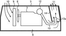
- FIG. 10 is a schematic view of a cross section of the engine room 6 as viewed from the back side of the engine room 6.
- a cooling fan 8 driven by the engine 7 and a heat exchanger 9 such as a radiator are provided at one end side of the engine 7 in the engine room 6, a cooling fan 8 driven by the engine 7 and a heat exchanger 9 such as a radiator are provided.
- An intake port 10 is provided in the portion of the upper surface wall of the engine cover 5 where the fan 8 and the heat exchanger 9 are provided, and an exhaust port 11 is provided in the opposite portion of the upper surface wall. It has been. Due to the rotation of the fan 8, outside air is introduced into the engine room 6 through the intake port 10 and passes through the heat exchanger 9, and cooled air (hereinafter referred to as exhaust air) is discharged from the exhaust port 11. Yes.
- a silencer (muffler) 12 is provided on the other end side of the engine 7.
- the exhaust gas emitted from the engine 7 is discharged to the outside through the silencer 12 and the exhaust gas pipe (tail pipe) 13 connected thereto.
- the exhaust gas has a high temperature (for example, 500 ° C.)
- the surrounding temperature environment is deteriorated.
- leakage of operation noise such as engine noise, exhaust noise, and exhaust wind noise to the outside increases.
- a cylindrical duct 14 is provided at a position below the exhaust port 11 in the engine room 6, the upper end of the duct 14 is opened to the exhaust port 11 side, and the lower end of the duct 14 is the engine room 6.
- the exhaust pipe 13 is provided so as to extend in the vertical direction while being opened inward, and the distal end portion 13 a of the exhaust gas pipe 13 is bent upward below the duct 14, and the distal end portion 13 a is inserted into the duct 14 from the lower end of the duct 14. Yes.
- exhaust gas and exhaust air are greatly different in pressure and flow velocity. Specifically, the exhaust gas has higher pressure and flow velocity than the exhaust air. For this reason, the exhaust gas and the exhaust air are originally difficult to mix.
- the tip end portion 13a of the exhaust gas pipe 13 is inserted upward into the duct 14 as shown in the figure, and the exhaust gas is concentrated from the opening of the tip end portion 13a, that is, from one point and in the duct 14. It is configured to inject in the same direction as the exhaust air. For this reason, the mixing efficiency of exhaust gas and exhaust air becomes worse. For this reason, the effect of lowering the exhaust gas temperature is low.
- An object of the present invention is to provide a construction machine capable of enhancing the mixing efficiency of exhaust gas and exhaust air and the sound reduction effect in a duct.
- a construction machine includes an engine room having an intake port and an exhaust port, a fan for sucking cooling air into the engine room through the intake port, and the exhaust port in the engine room.
- a duct that is provided so as to communicate with the cooling air sucked into the engine room and exhausts the cooling air to the outside of the engine room through the exhaust port, and guides exhaust gas discharged from the engine into the duct.
- the exhaust gas pipe has a tip side portion inserted into the duct, and the exhaust gas pipe inserted into the duct has an exhaust gas flow direction of the exhaust air in the duct. Discharge holes are provided to discharge in different directions.
- a construction machine includes an engine room provided with an intake port and an exhaust port, a fan for sucking cooling air into the engine room through the intake port, and the engine room with the above A duct provided so as to communicate with an exhaust port, and for discharging the cooling air sucked into the engine room to the outside of the engine room through the exhaust port; and an exhaust gas discharged from the engine.
- a portion of the exhaust gas pipe on the tip side is inserted into the duct, and the exhaust gas pipe inserted into the duct has a length of the insertion portion.
- Discharge holes are provided for discharging in a distributed manner.
- a construction machine includes an engine room provided with an intake port and an exhaust port, a fan for sucking cooling air into the engine room through the intake port, and the engine room.
- a duct that is provided to communicate with the exhaust port and that discharges the cooling air sucked into the engine room to the outside of the engine room through the exhaust port, and exhaust gas discharged from the engine
- An exhaust gas pipe that leads into the duct, and a portion of the exhaust gas pipe on the tip side is inserted into the duct, and the exhaust gas pipe is inserted into the duct to insert the exhaust gas into the duct.
- a discharge hole for discharging in a direction different from the flow direction of the wind and discharging in the length direction of the insertion portion is provided.
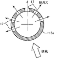
- FIG. 3 is an enlarged cross-sectional view of a portion where an exhaust gas pipe is inserted along line III-III in FIG. 2.
- FIG. 3 is an enlarged cross-sectional view of a portion where an exhaust gas pipe is inserted along line III-III in FIG. 2.
- 1 is an overall schematic side view of a hydraulic excavator to which the present invention is applied. It is a schematic sectional drawing of the engine room by a well-known technique.
- An engine room 6 is formed by the engine cover 5 at the rear of the upper swing body, and the engine 7 and related devices are accommodated in the engine room 6.
- a cooling fan 8 driven by the engine 7 and a heat exchanger 9 such as a radiator are provided on one end side of the engine 7 in the engine room 6, a cooling fan 8 driven by the engine 7 and a heat exchanger 9 such as a radiator (all shown only in FIG. 1) are provided. .
- An air inlet 10 (shown only in FIG. 1) is provided on the upper surface wall near the end of the engine cover 5 on the side where the fan 8 and the heat exchanger 9 are provided, and the upper surface wall near the opposite end. Is provided with an exhaust port 11. Due to the rotation of the fan 8, outside air is introduced into the engine room 6 through the air inlet 10, passes through the heat exchanger 9, and cooled air (hereinafter referred to as exhaust air) after cooling the heat exchanger 9 is exhausted. 11 is discharged.
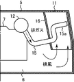
- a silencer (muffler) 12 is provided at the other end of the engine 7, and exhaust gas from the engine 7 passes through the silencer 12 and an exhaust pipe (tail pipe) 15 connected to the silencer 12. It is discharged outside.
- a cylindrical duct 16 is located below the exhaust port 11, the upper end of the duct 16 opens to the exhaust port 11 side, and the lower end of the duct 16 is in the engine room 6. It is provided so as to extend in the vertical direction in an open state. The exhaust air and the exhaust gas are guided into the duct 16 and mixed with each other. As a result, the exhaust gas temperature is lowered and the exhaust air and the exhaust gas are discharged to the outside. The sound is reduced.
- the exhaust gas pipe 15 is bent toward the duct 16 at an intermediate portion thereof.
- a portion of the exhaust gas pipe 15 on the front end side (opposite to the engine 7) is inserted into the duct 16 through the side wall of the duct 16. That is, the insertion portion 15a, which is a portion on the tip side of the exhaust gas pipe 15, extends in a direction intersecting (preferably orthogonal) as shown in FIG. It is inserted into the duct 16.
- a plurality of discharge holes 17 for injecting exhaust gas flowing through the insertion portion 15 a into the duct 16 is provided in the insertion portion 15 a of the exhaust gas pipe 15.
- the plurality of discharge holes 17 are formed on the insertion portion 15a on the leeward side of the exhaust air passing through the duct 16 (above the line extending in the radial direction of the insertion portion 15a perpendicular to the flow direction of the exhaust air).
- Half-circumferential part As shown in the figure, the discharge holes 17 are provided at a plurality of different locations spaced apart in the circumferential direction in the half circumference portion of the insertion portion 15a and are spaced apart in the length direction of the insertion portion 15a. Are provided at different locations.
- the area opened by the discharge hole 17 per unit length of the insertion portion 15a is such that the amount of exhaust gas discharged from the discharge hole 17 is substantially uniform in the length direction of the insertion portion 15a. It gradually decreases toward the tip end side of 15a (the side opposite to the engine 7). In other words, the ratio of the area opened by the discharge hole 17 to the area of the portion not opened in the insertion portion 15a is gradually reduced toward the distal end side of the insertion portion 15a. The amount of exhaust gas discharged becomes substantially uniform in the length direction of the insertion portion 15a.
- the installation interval of the discharge holes 17 in the length direction of the insertion portion 15a is gradually increased toward the distal end side of the insertion portion 15a. That is, the installation density of the discharge holes 17 is gradually reduced toward the distal end side of the insertion portion 15a.
- the size of the discharge hole 17 disposed closer to the distal end side of the insertion portion 15a may be reduced.
- the discharge hole 17 may be a round hole as shown or a square hole. Or the discharge hole 17 is good also as a slot long in the length direction of the insertion part 15a. When the discharge hole 17 is a slot, the width dimension may be gradually reduced toward the distal end side of the insertion portion 15a.
- the opening at the tip of the exhaust gas pipe 15 is closed or narrowed to a small opening area.
- the exhaust gas is inserted into the duct 16 from a portion of the insertion portion 15a located on the leeward side of the exhaust air (see FIG. 3) and extending over almost the entire length of the insertion portion 15a. Injected radially with respect to the center (diameter center) of the portion 15a.
- the exhaust gas is (I) Injected in a direction different from the flow direction of the exhaust air in the duct 16, and (ii) Dispersed and injected in the circumferential direction and the length direction of the insertion portion 15a.
- the exhaust gas whose pressure and flow velocity are higher than the exhaust air stays in a wide area range in the cross section of the duct 16. Easy to mix with low-pressure, low-speed exhaust.
- the exhaust gas is mixed with the exhaust air in a wider range in the duct 16 due to the diffusion action of the exhaust gas in the circumferential direction and the length direction of (ii) above.
- the mixing efficiency of the exhaust gas and the exhaust air can be increased.
- the exhaust gas and the exhaust air are discharged from the duct 16 and the exhaust port 11 after the temperature of the exhaust gas is reliably lowered to a preferable temperature. It can be discharged to the outside.
- the exhaust gas and the exhaust air can be discharged outside after the temperature of the exhaust gas is reduced from 500 ° C. to 100 ° C.
- the exhaust gas injection action of (i) and (ii) makes it easy for the exhaust sound of exhaust gas (exhaust sound) to come into contact with the inner surface of the duct 16, and rides on the exhaust wind from the engine 7 and the silencer 12.
- the noise that is about to be emitted to the outside is easily diffused and reflected in the duct 16 together with the exhaust gas, so that the operating noise discharged to the outside can be reduced.
- the effect of reducing the exhaust gas temperature and the effect of reducing noise can be remarkably enhanced as compared with known techniques.
- the duct 16 is bent so that the upper part faces the opposite side of the engine 7.
- the insertion portion 15 a of the exhaust gas pipe 15 is disposed on the upstream side (lower portion of the duct) in the exhaust air flow direction with respect to the bent portion 16 a which is a bent portion of the duct 16.
- the duct 16 has an outlet side opening 16b that is an outlet of exhaust air flowing through the duct 16, and the insertion portion 15a of the exhaust gas pipe 15 cannot be directly viewed from the outside through the outlet opening 16b of the duct 16. Is inserted into the duct 16.
- a sound absorbing material 18 made of glass wool or the like is provided on the entire bent portion 16a of the duct 16 and the inner surface of the lower portion thereof.
- the duct 16 in addition to the same basic functions and effects as those of the first embodiment, by providing the duct 16 with the bent portion 16a, it becomes difficult for the entire noise to leak to the outside, and the insertion portion of the exhaust pipe 15 is inserted.
- the duct 16 By arranging 15a on the upstream side of the bent portion 16a, it is possible to obtain an operation effect that exhaust gas exhaust gas hardly leaks to the outside.
- the insertion portion 15a of the exhaust gas pipe 15 is provided in the duct 16 at a position where it cannot be directly viewed from the outside through the outlet side opening 16b of the duct 16, so that noise is directly emitted from the duct 16 to the outside. It is possible to prevent the occurrence of “direct sound”.
- the operation noise including the exhaust sound diffused in the duct 16 as described above is efficiently absorbed by the sound absorbing material 18. For this reason, this second embodiment is further advantageous in terms of prevention or reduction of noise.
- the outlet side opening 16b of the duct 16 also serves as an exhaust port.
- the insertion portion 15a of the exhaust gas pipe 15 may be provided in a state where only a part of the insertion portion 15a can be directly viewed from the outside through the outlet opening 16b of the duct 16.
- the discharge hole (not shown in FIGS. 5 and 6) is provided only in the lateral side portion extending in the lateral direction of the L-shaped portion or the inverted L-shaped portion of the insertion portion 15a (front end side portion). You may provide only in the vertical side part extended in the vertical direction among those parts. Or you may provide a discharge hole in both a horizontal side part and a vertical side part.
- the exhaust holes are dispersed and injected in the length direction and the circumferential direction of the portion where the exhaust hole is provided in the insertion portion 15a (front end side portion) through the exhaust hole. It is desirable to be provided in such a state.
- the exhaust gas can be diffused more widely in the duct 16.
- FIG. 5 and 6 show the duct configuration of the first embodiment in which the duct 16 is a straight pipe extending in the vertical direction, the configurations of the third and fourth embodiments are shown in FIG.
- the present invention can also be applied to a duct configuration in which the bent portion 16a is provided in the duct 16.
- the insertion portion 15 a of the exhaust gas pipe 15 is inserted upward into the duct 16 from the opening 16 c on the inlet side of the duct 16 as in the known technique.
- the exhaust gas is injected from the insertion portion 15a in a direction different from the flow direction of the exhaust air in the duct 16, specifically, laterally, and the circumferential direction and the length direction of the insertion portion 15a.
- the insertion portion 15a is configured to be dispersed and injected.
- the insertion part 15a may be comprised so that waste gas may be disperse
- the present invention is not limited to the hydraulic excavator, and can be applied to other construction machines having an engine room and configured to discharge cooling air and exhaust gas from the engine room to the outside.
- a part of the duct 16 may be constituted by the engine cover 5.
- a part of the side wall of the duct 16 may be constituted by a part of the side wall of the engine cover 5.
- FIG. 8 shows an example in which a part of the duct 16 is configured by the engine cover 5 in the third embodiment, but a part of the duct 16 is similarly applied to each of the embodiments other than the third embodiment. May be constituted by the engine cover 5.
- the construction machine includes an engine room having an intake port and an exhaust port, a fan for sucking cooling air into the engine room through the intake port, and the exhaust port in the engine room.
- a duct for discharging the cooling air sucked into the engine room to the outside of the engine room through the exhaust port, and an exhaust gas for guiding the exhaust gas discharged from the engine into the duct A portion on the tip side of the exhaust gas pipe is inserted into the duct, and the exhaust gas pipe inserted into the duct has an exhaust gas flow direction of exhaust air in the duct.
- Discharge holes for discharging in different directions are provided.
- the exhaust gas is not injected in the flow direction of the exhaust air as in the known technique, but is discharged in a direction different from the flow direction of the exhaust air in the duct.
- the exhaust gas since the exhaust gas has high pressure and flow velocity, the exhaust gas is injected in a direction different from the flow direction of the exhaust air in the duct, thereby mixing the exhaust air and the duct in a wide area range. For this reason, the mixing efficiency of exhaust gas and exhaust air is improved, and the effect of reducing exhaust gas temperature can be enhanced.
- the exhaust gas is injected in a direction different from the flow direction of the exhaust air and diffuses in the duct, it is possible to obtain a sound attenuation effect due to the sound reflection on the inner surface of the duct.
- the sound reduction effect can be improved.
- the noise reduction effect can be enhanced.
- the construction machine includes an engine room having an intake port and an exhaust port, a fan for sucking cooling air into the engine room through the intake port, and the exhaust port in the engine room. And a duct for discharging the cooling air sucked into the engine room to the outside of the engine room through the exhaust port, and exhaust gas discharged from the engine into the duct.
- a portion of the exhaust gas pipe on the tip side is inserted into the duct, and the exhaust gas pipe inserted into the duct has an exhaust gas in the length direction of the insertion portion.
- Discharge holes for discharging in a dispersed manner are provided.
- the exhaust hole for discharging the exhaust gas in a direction different from the flow direction of the exhaust air in the duct has the exhaust gas pipe.
- the mixing efficiency of exhaust gas and exhaust air can be increased and the sound reduction effect can be increased, and the exhaust gas temperature reduction effect and noise reduction effect can be enhanced.
- the construction machine includes an engine room having an intake port and an exhaust port, a fan for sucking cooling air into the engine room through the intake port, and the exhaust port in the engine room. And a duct for discharging the cooling air sucked into the engine room to the outside of the engine room through the exhaust port, and exhaust gas discharged from the engine into the duct.
- a portion of the exhaust gas pipe on the tip side is inserted into the duct, and the exhaust gas flow into the duct is inserted into the insertion portion of the exhaust gas pipe inserted into the duct.
- Discharge holes are provided for discharging in a direction different from the direction and discharging in the length direction of the insertion portion.
- the insertion portion of the exhaust gas pipe is inserted into the duct so as to extend in a direction intersecting with a direction in which the duct extends.
- the exhaust pipe insertion portion can be positioned over a wide range of the cross section of the duct in a state of traversing the inside of the duct, so that the exhaust hole discharges the exhaust gas in a direction different from the flow direction of the exhaust air.
- the exhaust gas is injected from the insertion portion of the exhaust gas pipe into a wide range in the duct. Becomes easy.
- the exhaust hole is provided in a half-circumferential portion located on the leeward side of the exhaust air in the duct in the insertion portion of the exhaust gas pipe.
- the exhaust hole may be provided at a plurality of different locations in the circumferential direction of the insertion portion of the exhaust gas pipe.
- the discharge hole may be provided at a plurality of different locations in the length direction of the insertion portion of the exhaust gas pipe.
- the discharge hole may be provided at a plurality of different locations in the circumferential direction of the insertion portion and at a plurality of different locations in the length direction of the insertion portion.
- the discharge hole may be a slot extending over a predetermined length range (for example, a substantially full length portion) of the insertion portion of the exhaust gas pipe.
- the area opened by the discharge hole per unit length of the insertion portion is such that the amount of exhaust gas discharged from the discharge hole is substantially uniform in the length direction of the insertion portion. It is desirable that the diameter gradually decreases toward the distal end side of the insertion portion.
- the ratio of the area opened by the discharge hole is relatively small on the distal end side of the insertion portion where the exhaust gas flow velocity is the highest, and from the distal end side toward the opposite side where the exhaust gas flow velocity is low.
- the ratio of the area opened by the discharge holes gradually increases.
- the amount of exhaust gas discharged is substantially uniform in the length direction of the insertion portion of the exhaust gas pipe, and as a result, it is advantageous in terms of the mixing efficiency of the exhaust gas and the exhaust air and the noise reduction effect.
- the duct is provided with at least one bent portion, and the insertion portion of the exhaust pipe is disposed upstream of the bent portion in the flow direction of the exhaust air in the duct. It is desirable that
- the entire noise is hardly leaked to the outside by the bent portion provided in the duct, and the insertion portion of the exhaust gas pipe is disposed upstream of the bent portion in the exhaust air flow direction.
- exhaust gas exhaust sound is less likely to leak to the outside.
- the duct has an outlet-side opening that is an outlet for exhaust air flowing through the duct, and the insertion portion of the exhaust gas pipe is provided in a state where it cannot be directly viewed from the outside through the outlet-side opening of the duct. It is desirable that
- the mixing efficiency of exhaust gas and exhaust air in the duct and the sound reduction effect can be enhanced, and the exhaust gas temperature reduction effect and noise reduction effect can be enhanced.
Landscapes
- Engineering & Computer Science (AREA)
- General Engineering & Computer Science (AREA)
- Chemical & Material Sciences (AREA)
- Mining & Mineral Resources (AREA)
- Combustion & Propulsion (AREA)
- Mechanical Engineering (AREA)
- Civil Engineering (AREA)
- Structural Engineering (AREA)
- Health & Medical Sciences (AREA)
- Chemical Kinetics & Catalysis (AREA)
- Toxicology (AREA)
- Life Sciences & Earth Sciences (AREA)
- General Life Sciences & Earth Sciences (AREA)
- Paleontology (AREA)
- Transportation (AREA)
- Exhaust Silencers (AREA)
- Component Parts Of Construction Machinery (AREA)
- Exhaust Gas After Treatment (AREA)
Abstract
Description
第1実施形態において、排ガス管15は、その中間部でダクト16側に折り曲げられている。当該排ガス管15の先端側(エンジン7と反対側)の部分は、ダクト16の側壁を貫いてダクト16内に挿入されている。すなわち、排ガス管15の先端側の部分である挿入部分15aは、ダクト16が延びる方向と交差(望ましくは図示のように直交)する方向に延び、且つ、ダクト16内をほぼ横断する状態でそのダクト16内に挿入されている。
(i) ダクト16内の排風の流れ方向と異なる方向に噴射され、且つ
(ii) 挿入部分15aの周方向及び長さ方向において分散して噴射される。
以下の実施形態については、第1実施形態と同一部分には同一符号を付して示し、第1実施形態との相違点のみを説明する。
図4に示す第2実施形態では、ダクト16は、その上部がエンジン7と反対側を向くように折り曲げられている。排ガス管15の挿入部分15aは、ダクト16の折り曲げられた部分である曲げ部16aよりも排風の流れ方向において上流側(ダクト下部)に配置されている。また、ダクト16は、当該ダクト16内を流れる排風の出口である出口側開口16bを有しており、排ガス管15の挿入部分15aは、このダクト16の出口開口16bを通して外部から直視できない状態でダクト16内に挿入されている。
図5に示す第3実施形態では、ダクト16内に挿入されている排ガス管15の挿入部分15aが下方に折り曲げられているとともに、その下方への折曲部よりも先端側に位置する部分が背面から見てL字形になるようにさらに折り曲げられている。また、図6に示す第4実施形態では、ダクト16内に挿入されている排ガス管15の挿入部分15aが上方に折り曲げられているとともに、その上方への折曲部よりも先端側に位置する部分が背面から見て逆L字形になるようにさらに折り曲げられている。
図7に示す第5実施形態においては、公知技術と同様、排ガス管15の挿入部分15aがダクト16の入口側の開口16cからダクト16内に上向きに挿入されている。そして、この第5実施形態では、排ガスが挿入部分15aから、ダクト16内における排風の流れ方向と異なる方向、具体的には横向きに噴射され、かつ、挿入部分15aの周方向及び長さ方向に分散して噴射されるように、挿入部分15aが構成されている。なお、排ガスは挿入部分15aの周方向及び長さ方向のうちの一方のみにおいて分散して噴射されるように、挿入部分15aが構成されていてもよい。
図8に示すように、ダクト16の一部は、エンジンカバー5によって構成されていてもよい。具体的には、ダクト16の側壁の一部が、エンジンカバー5の側壁の一部によって構成されていてもよい。なお、図8では、上記第3実施形態においてダクト16の一部をエンジンカバー5で構成した例を示したが、第3実施形態以外の上記各実施形態においても同様に、ダクト16の一部をエンジンカバー5によって構成してもよい。
前記実施形態をまとめると、以下の通りである。
Claims (10)
- 吸気口と排気口を備えたエンジンルームと、
上記吸気口を通じて上記エンジンルーム内に冷却用空気を吸い込むためのファンと、
上記エンジンルーム内に上記排気口と連通するように設けられ、上記エンジンルーム内に吸い込まれた上記冷却用空気を上記排気口を通じて上記エンジンルームの外部へ排出するためのダクトと、
上記エンジンから排出される排ガスを上記ダクト内に導く排ガス管とを備え、
上記排ガス管のうち先端側の部分は、上記ダクト内に挿入され、このダクト内に挿入された排ガス管の挿入部分には、排ガスを上記ダクト内の排風の流れ方向と異なる方向に排出する排出穴が設けられている、建設機械。 - 吸気口と排気口を備えたエンジンルームと、
上記吸気口を通じて上記エンジンルーム内に冷却用空気を吸い込むためのファンと、
上記エンジンルーム内に上記排気口と連通するように設けられ、上記エンジンルーム内に吸い込まれた上記冷却用空気を上記排気口を通じて上記エンジンルームの外部へ排出するためのダクトと、
上記エンジンから排出される排ガスを上記ダクト内に導く排ガス管とを備え、
上記排ガス管のうち先端側の部分は、上記ダクト内に挿入され、このダクト内に挿入された排ガス管の挿入部分には、排ガスを当該挿入部分の長さ方向に分散させて排出する排出穴が設けられている、建設機械。 - 吸気口と排気口を備えたエンジンルームと、
上記吸気口を通じて上記エンジンルーム内に冷却用空気を吸い込むためのファンと、
上記エンジンルーム内に上記排気口と連通するように設けられ、上記エンジンルーム内に吸い込まれた上記冷却用空気を上記排気口を通じて上記エンジンルームの外部へ排出するためのダクトと、
上記エンジンから排出される排ガスを上記ダクト内に導く排ガス管とを備え、
上記排ガス管のうち先端側の部分は、上記ダクト内に挿入され、このダクト内に挿入された排ガス管の挿入部分には、排ガスを上記ダクト内の排風の流れ方向と異なる方向に排出するとともに当該挿入部分の長さ方向に分散させて排出する排出穴が設けられている、建設機械。 - 請求項1~3のいずれか1項に記載の建設機械において、
上記排ガス管の上記挿入部分は、上記ダクトが延びる方向と交差する方向に延びるように上記ダクト内に挿入されている、建設機械。 - 請求項4に記載の建設機械において、
上記排出穴は、上記排ガス管の上記挿入部分のうち上記ダクト内の排風の風下側に位置する半周部分に設けられている、建設機械。 - 請求項1~5のいずれか1項に記載の建設機械において、
上記排出穴は、上記排ガス管の上記挿入部分の周方向において複数の異なる個所に設けられている、建設機械。 - 請求項1~6のいずれか1項に記載の建設機械において、
上記排出穴は、上記排ガス管の上記挿入部分の長さ方向において複数の異なる箇所に設けられている、建設機械。 - 請求項7に記載の建設機械において、
上記挿入部分の単位長さ当たりに上記排出穴によって開口されている面積は、上記排出穴から排出される排ガス量が上記挿入部分の長さ方向においてほぼ均等となるように、上記挿入部分の先端側へ向かうにつれて漸減している、建設機械。 - 請求項1~8のいずれか1項に記載の建設機械において、
上記ダクトには、少なくとも一つの曲げ部が設けられ、
上記排ガス管の上記挿入部分は、上記曲げ部よりも上記ダクト内の排風の流れ方向における上流側に配置されている、建設機械。 - 請求項9に記載の建設機械において、
上記ダクトは、当該ダクト内を流れる排風の出口である出口側開口を有し、
上記排ガス管の上記挿入部分は、上記ダクトの上記出口側開口を通して外部から直視できない状態で設けられている、建設機械。
Priority Applications (4)
| Application Number | Priority Date | Filing Date | Title |
|---|---|---|---|
| CN201280035597.2A CN103688029B (zh) | 2011-07-19 | 2012-07-11 | 工程机械 |
| US14/233,022 US9347202B2 (en) | 2011-07-19 | 2012-07-11 | Construction machine |
| EP12814762.6A EP2735711B1 (en) | 2011-07-19 | 2012-07-11 | Construction machine |
| KR1020147003848A KR101632805B1 (ko) | 2011-07-19 | 2012-07-11 | 건설 기계 |
Applications Claiming Priority (2)
| Application Number | Priority Date | Filing Date | Title |
|---|---|---|---|
| JP2011-157829 | 2011-07-19 | ||
| JP2011157829A JP5886551B2 (ja) | 2011-07-19 | 2011-07-19 | 建設機械の排気構造 |
Publications (1)
| Publication Number | Publication Date |
|---|---|
| WO2013011665A1 true WO2013011665A1 (ja) | 2013-01-24 |
Family
ID=47557866
Family Applications (1)
| Application Number | Title | Priority Date | Filing Date |
|---|---|---|---|
| PCT/JP2012/004483 Ceased WO2013011665A1 (ja) | 2011-07-19 | 2012-07-11 | 建設機械 |
Country Status (6)
| Country | Link |
|---|---|
| US (1) | US9347202B2 (ja) |
| EP (1) | EP2735711B1 (ja) |
| JP (1) | JP5886551B2 (ja) |
| KR (1) | KR101632805B1 (ja) |
| CN (1) | CN103688029B (ja) |
| WO (1) | WO2013011665A1 (ja) |
Cited By (3)
| Publication number | Priority date | Publication date | Assignee | Title |
|---|---|---|---|---|
| EP2792867A1 (en) * | 2013-04-19 | 2014-10-22 | Kobelco Construction Machinery Co., Ltd. | Exhaust apparatus of construction machine |
| EP2863029A1 (en) * | 2013-10-15 | 2015-04-22 | Kobelco Construction Machinery Co., Ltd. | Exhaust gas discharge apparatus for construction machine |
| JP2018203171A (ja) * | 2017-06-08 | 2018-12-27 | コベルコ建機株式会社 | キャビンヒーター用排気装置 |
Families Citing this family (16)
| Publication number | Priority date | Publication date | Assignee | Title |
|---|---|---|---|---|
| DK3153383T3 (da) | 2013-03-25 | 2019-12-02 | Polaris Inc | Terrængående bæltekøretøj |
| JP5962686B2 (ja) * | 2014-01-30 | 2016-08-03 | コベルコ建機株式会社 | 建設機械の電装品冷却構造 |
| JP6040178B2 (ja) * | 2014-02-13 | 2016-12-07 | 日立建機株式会社 | 排気ガス温度低減装置 |
| EP3155248B1 (en) * | 2014-06-13 | 2018-07-04 | Wärtsilä Finland Oy | Monitoring system for gas engine |
| WO2015079749A1 (ja) | 2014-08-19 | 2015-06-04 | 株式会社小松製作所 | 作業車両 |
| CN105986591B (zh) * | 2015-03-20 | 2021-07-27 | 住友建机株式会社 | 小回转型挖土机 |
| JP6687433B2 (ja) * | 2016-03-16 | 2020-04-22 | 本田技研工業株式会社 | エンジン駆動作業機 |
| KR102440166B1 (ko) | 2016-03-18 | 2022-09-02 | 엘에스엠트론 주식회사 | 농업용 작업차량의 배기가스 분산장치 |
| JP6069595B1 (ja) * | 2016-03-31 | 2017-02-01 | 株式会社小松製作所 | ダンプトラック |
| US10569642B2 (en) * | 2016-06-20 | 2020-02-25 | Polaris Industries Inc. | Cooling system for an all terrain vehicle |
| CN109983417B (zh) * | 2017-07-18 | 2022-01-18 | 株式会社久保田 | 作业机 |
| JP7585185B2 (ja) | 2021-12-28 | 2024-11-18 | 株式会社クボタ | 作業機 |
| DE102022110879B3 (de) * | 2022-05-03 | 2023-03-02 | Liebherr-Werk Bischofshofen Gmbh | Arbeitsmaschine |
| CN117537547A (zh) * | 2022-08-01 | 2024-02-09 | 湖北美的电冰箱有限公司 | 压机舱组件和电器设备 |
| CN117967438B (zh) * | 2024-03-29 | 2024-06-04 | 泰州市曙明塑胶有限公司 | 一种汽车发动机的风扇塑料护风罩 |
| CN119754929A (zh) * | 2025-03-06 | 2025-04-04 | 首帆动力科技股份有限公司 | 一种超静音柴油发电机组 |
Citations (3)
| Publication number | Priority date | Publication date | Assignee | Title |
|---|---|---|---|---|
| JPH03229907A (ja) | 1989-11-02 | 1991-10-11 | Komatsu Ltd | エンジン室内蔵エンジン吸排気装置 |
| JPH07139369A (ja) * | 1993-11-19 | 1995-05-30 | Mitsubishi Heavy Ind Ltd | エンクロージャの防音冷却換気構造 |
| JP2011064068A (ja) * | 2009-09-15 | 2011-03-31 | Hino Motors Ltd | 排気浄化装置 |
Family Cites Families (28)
| Publication number | Priority date | Publication date | Assignee | Title |
|---|---|---|---|---|
| US4388804A (en) * | 1981-08-17 | 1983-06-21 | J. I. Case Company | Exhaust assembly for tractors |
| US4903484A (en) * | 1989-05-08 | 1990-02-27 | Yates Clyde I | Exhaust dissipator and deflector |
| JPH0337222U (ja) * | 1989-08-23 | 1991-04-11 | ||
| JPH05312050A (ja) * | 1992-05-01 | 1993-11-22 | Kubota Corp | 防音型エンジン発電機の換気冷却装置 |
| KR19990005042A (ko) * | 1997-06-30 | 1999-01-25 | 김영귀 | 차량의 소음기 |
| KR20000006762U (ko) * | 1998-09-21 | 2000-04-25 | 김형벽 | 엔진 배기장치 |
| JP2002285858A (ja) * | 2001-03-27 | 2002-10-03 | Asahi Denki Kk | 可搬形又は車載形の発電装置 |
| JP2002317631A (ja) * | 2001-04-23 | 2002-10-31 | Komatsu Ltd | エンジン排気ガス排出装置 |
| US6832872B2 (en) * | 2002-11-13 | 2004-12-21 | Blaw-Knox Construction Equipment Corporation | Gas discharge device for a construction vehicle |
| JP2004353461A (ja) * | 2003-05-27 | 2004-12-16 | Nishishiba Electric Co Ltd | パッケージ型発電装置 |
| JP2005264870A (ja) * | 2004-03-19 | 2005-09-29 | Denyo Co Ltd | 防音型エンジン駆動作業機 |
| JP4326479B2 (ja) * | 2005-01-20 | 2009-09-09 | 本田技研工業株式会社 | エンジン駆動式作業機 |
| US7314397B2 (en) * | 2005-05-13 | 2008-01-01 | Briggs & Stratton Corporation | Standby generator |
| JP4578336B2 (ja) * | 2005-05-31 | 2010-11-10 | デンヨー株式会社 | エンジン駆動作業機 |
| US7703573B2 (en) * | 2005-08-05 | 2010-04-27 | Paccar Inc | Ported aerodynamic exhaust tailpipe |
| US7971432B2 (en) * | 2007-07-13 | 2011-07-05 | Paccar Inc | Flow diffuser for exhaust pipe |
| JP2009030559A (ja) * | 2007-07-30 | 2009-02-12 | Caterpillar Japan Ltd | 建設機械における排気構造 |
| JP5292534B2 (ja) * | 2007-08-08 | 2013-09-18 | 日野自動車株式会社 | 排気浄化装置 |
| US20090071136A1 (en) * | 2007-09-14 | 2009-03-19 | Mack Trucks, Inc. | Exhaust diffuser for an internal combustion engine |
| US8033104B2 (en) * | 2008-07-09 | 2011-10-11 | Ford Global Technologies, Llc | Selective catalytic reduction (SCR) catalyst injection systems |
| KR20100061875A (ko) * | 2008-12-01 | 2010-06-10 | 볼보 컨스트럭션 이키프먼트 홀딩 스웨덴 에이비 | 건설기계용 배기가스 저온화 장치 |
| KR101026190B1 (ko) * | 2009-01-23 | 2011-03-31 | 볼보 컨스트럭션 이큅먼트 에이비 | 엔진룸의 과열가스 온도 저감장치 |
| US7958966B2 (en) * | 2009-03-31 | 2011-06-14 | Paccar Inc | Exhaust stack fairing |
| DE102009046253A1 (de) * | 2009-10-30 | 2011-05-05 | Deere & Company, Moline | Vorrichtung zur Kühlung eines Abgasstroms |
| JP2011106287A (ja) * | 2009-11-12 | 2011-06-02 | Yanmar Co Ltd | エンジン発電装置 |
| JP2014504692A (ja) * | 2010-12-27 | 2014-02-24 | ボルボ コンストラクション イクイップメント アーベー | 建設機械用排ガス処理装置 |
| US20120318602A1 (en) * | 2011-06-20 | 2012-12-20 | Caterpillar Inc. | Exhaust System for Machine |
| US8550208B1 (en) * | 2012-04-23 | 2013-10-08 | General Electric Company | High pressure muffling devices |
-
2011
- 2011-07-19 JP JP2011157829A patent/JP5886551B2/ja active Active
-
2012
- 2012-07-11 CN CN201280035597.2A patent/CN103688029B/zh not_active Expired - Fee Related
- 2012-07-11 WO PCT/JP2012/004483 patent/WO2013011665A1/ja not_active Ceased
- 2012-07-11 US US14/233,022 patent/US9347202B2/en not_active Expired - Fee Related
- 2012-07-11 EP EP12814762.6A patent/EP2735711B1/en not_active Not-in-force
- 2012-07-11 KR KR1020147003848A patent/KR101632805B1/ko not_active Expired - Fee Related
Patent Citations (3)
| Publication number | Priority date | Publication date | Assignee | Title |
|---|---|---|---|---|
| JPH03229907A (ja) | 1989-11-02 | 1991-10-11 | Komatsu Ltd | エンジン室内蔵エンジン吸排気装置 |
| JPH07139369A (ja) * | 1993-11-19 | 1995-05-30 | Mitsubishi Heavy Ind Ltd | エンクロージャの防音冷却換気構造 |
| JP2011064068A (ja) * | 2009-09-15 | 2011-03-31 | Hino Motors Ltd | 排気浄化装置 |
Cited By (6)
| Publication number | Priority date | Publication date | Assignee | Title |
|---|---|---|---|---|
| EP2792867A1 (en) * | 2013-04-19 | 2014-10-22 | Kobelco Construction Machinery Co., Ltd. | Exhaust apparatus of construction machine |
| CN104110295A (zh) * | 2013-04-19 | 2014-10-22 | 神钢建机株式会社 | 工程机械的排气装置 |
| US9238989B2 (en) | 2013-04-19 | 2016-01-19 | Kobelco Construction Machinery Co., Ltd. | Exhaust apparatus of construction machine |
| EP2863029A1 (en) * | 2013-10-15 | 2015-04-22 | Kobelco Construction Machinery Co., Ltd. | Exhaust gas discharge apparatus for construction machine |
| US9359931B2 (en) | 2013-10-15 | 2016-06-07 | Kobelco Construction Machinery Co., Ltd. | Gas release apparatus for construction machine |
| JP2018203171A (ja) * | 2017-06-08 | 2018-12-27 | コベルコ建機株式会社 | キャビンヒーター用排気装置 |
Also Published As
| Publication number | Publication date |
|---|---|
| JP5886551B2 (ja) | 2016-03-16 |
| KR101632805B1 (ko) | 2016-06-22 |
| US20140151143A1 (en) | 2014-06-05 |
| EP2735711B1 (en) | 2017-09-06 |
| EP2735711A4 (en) | 2015-04-29 |
| CN103688029A (zh) | 2014-03-26 |
| KR20140048273A (ko) | 2014-04-23 |
| CN103688029B (zh) | 2016-01-20 |
| US9347202B2 (en) | 2016-05-24 |
| EP2735711A1 (en) | 2014-05-28 |
| JP2013024077A (ja) | 2013-02-04 |
Similar Documents
| Publication | Publication Date | Title |
|---|---|---|
| JP5886551B2 (ja) | 建設機械の排気構造 | |
| KR101610561B1 (ko) | 건설 기계 | |
| CN100560954C (zh) | 建筑机械的排气构造 | |
| JP2010024824A (ja) | 建設機械用ノイズサイレンサー | |
| JP2008174004A (ja) | 建設機械の冷却構造 | |
| JP6530977B2 (ja) | 建設機械の吸気構造 | |
| CN207513659U (zh) | 一种汽车消音器 | |
| JP5783216B2 (ja) | 建設機械の排気構造 | |
| JP6176297B2 (ja) | 建設機械 | |
| JP4160448B2 (ja) | 建設機械のエンジンルーム構造及び建設機械のエンジン冷却装置 | |
| KR101516928B1 (ko) | 차량용 소음기 | |
| JP2008261270A (ja) | 作業機械の冷却風排気構造 | |
| JP2017160639A (ja) | 作業機械の排気装置 | |
| JP2014163227A (ja) | 建設機械の排気構造 | |
| JP2014029151A (ja) | 建設機械の排気構造 | |
| JP4436293B2 (ja) | 建設機械の吸音ダクト | |
| KR200374553Y1 (ko) | 자동차용 배기구 | |
| JPH10266853A (ja) | 建設機械のエンジン排気構造 | |
| JP5955667B2 (ja) | 建設機械の排気装置及び排気装置を備える建設機械 | |
| KR19990010289U (ko) | 자동차 머플러의 흡음구조 | |
| JP2008196114A (ja) | 建設機械 | |
| JPH03248969A (ja) | 上部旋回式建設機械のカウンタウエイト | |
| JP2011021449A (ja) | エンジンルームの吸音構造 |
Legal Events
| Date | Code | Title | Description |
|---|---|---|---|
| 121 | Ep: the epo has been informed by wipo that ep was designated in this application |
Ref document number: 12814762 Country of ref document: EP Kind code of ref document: A1 |
|
| WWE | Wipo information: entry into national phase |
Ref document number: 14233022 Country of ref document: US |
|
| NENP | Non-entry into the national phase |
Ref country code: DE |
|
| REEP | Request for entry into the european phase |
Ref document number: 2012814762 Country of ref document: EP |
|
| WWE | Wipo information: entry into national phase |
Ref document number: 2012814762 Country of ref document: EP |
|
| ENP | Entry into the national phase |
Ref document number: 20147003848 Country of ref document: KR Kind code of ref document: A |