WO2013011721A1 - 内視鏡装置 - Google Patents
内視鏡装置 Download PDFInfo
- Publication number
- WO2013011721A1 WO2013011721A1 PCT/JP2012/059479 JP2012059479W WO2013011721A1 WO 2013011721 A1 WO2013011721 A1 WO 2013011721A1 JP 2012059479 W JP2012059479 W JP 2012059479W WO 2013011721 A1 WO2013011721 A1 WO 2013011721A1
- Authority
- WO
- WIPO (PCT)
- Prior art keywords
- tip
- frame
- distal end
- end frame
- endoscope apparatus
- Prior art date
- Legal status (The legal status is an assumption and is not a legal conclusion. Google has not performed a legal analysis and makes no representation as to the accuracy of the status listed.)
- Ceased
Links
Images




Classifications
-
- A—HUMAN NECESSITIES
- A61—MEDICAL OR VETERINARY SCIENCE; HYGIENE
- A61B—DIAGNOSIS; SURGERY; IDENTIFICATION
- A61B1/00—Instruments for performing medical examinations of the interior of cavities or tubes of the body by visual or photographical inspection, e.g. endoscopes; Illuminating arrangements therefor
- A61B1/04—Instruments for performing medical examinations of the interior of cavities or tubes of the body by visual or photographical inspection, e.g. endoscopes; Illuminating arrangements therefor combined with photographic or television appliances
- A61B1/05—Instruments for performing medical examinations of the interior of cavities or tubes of the body by visual or photographical inspection, e.g. endoscopes; Illuminating arrangements therefor combined with photographic or television appliances characterised by the image sensor, e.g. camera, being in the distal end portion
- A61B1/051—Details of CCD assembly
-
- A—HUMAN NECESSITIES
- A61—MEDICAL OR VETERINARY SCIENCE; HYGIENE
- A61B—DIAGNOSIS; SURGERY; IDENTIFICATION
- A61B1/00—Instruments for performing medical examinations of the interior of cavities or tubes of the body by visual or photographical inspection, e.g. endoscopes; Illuminating arrangements therefor
- A61B1/00064—Constructional details of the endoscope body
- A61B1/00071—Insertion part of the endoscope body
- A61B1/0008—Insertion part of the endoscope body characterised by distal tip features
-
- A—HUMAN NECESSITIES
- A61—MEDICAL OR VETERINARY SCIENCE; HYGIENE
- A61B—DIAGNOSIS; SURGERY; IDENTIFICATION
- A61B1/00—Instruments for performing medical examinations of the interior of cavities or tubes of the body by visual or photographical inspection, e.g. endoscopes; Illuminating arrangements therefor
- A61B1/00064—Constructional details of the endoscope body
- A61B1/00071—Insertion part of the endoscope body
- A61B1/0008—Insertion part of the endoscope body characterised by distal tip features
- A61B1/00096—Optical elements
-
- A—HUMAN NECESSITIES
- A61—MEDICAL OR VETERINARY SCIENCE; HYGIENE
- A61B—DIAGNOSIS; SURGERY; IDENTIFICATION
- A61B1/00—Instruments for performing medical examinations of the interior of cavities or tubes of the body by visual or photographical inspection, e.g. endoscopes; Illuminating arrangements therefor
- A61B1/06—Instruments for performing medical examinations of the interior of cavities or tubes of the body by visual or photographical inspection, e.g. endoscopes; Illuminating arrangements therefor with illuminating arrangements
- A61B1/0661—Endoscope light sources
- A61B1/0676—Endoscope light sources at distal tip of an endoscope
-
- A—HUMAN NECESSITIES
- A61—MEDICAL OR VETERINARY SCIENCE; HYGIENE
- A61B—DIAGNOSIS; SURGERY; IDENTIFICATION
- A61B1/00—Instruments for performing medical examinations of the interior of cavities or tubes of the body by visual or photographical inspection, e.g. endoscopes; Illuminating arrangements therefor
- A61B1/06—Instruments for performing medical examinations of the interior of cavities or tubes of the body by visual or photographical inspection, e.g. endoscopes; Illuminating arrangements therefor with illuminating arrangements
- A61B1/07—Instruments for performing medical examinations of the interior of cavities or tubes of the body by visual or photographical inspection, e.g. endoscopes; Illuminating arrangements therefor with illuminating arrangements using light-conductive means, e.g. optical fibres
-
- A—HUMAN NECESSITIES
- A61—MEDICAL OR VETERINARY SCIENCE; HYGIENE
- A61B—DIAGNOSIS; SURGERY; IDENTIFICATION
- A61B1/00—Instruments for performing medical examinations of the interior of cavities or tubes of the body by visual or photographical inspection, e.g. endoscopes; Illuminating arrangements therefor
- A61B1/12—Instruments for performing medical examinations of the interior of cavities or tubes of the body by visual or photographical inspection, e.g. endoscopes; Illuminating arrangements therefor with cooling or rinsing arrangements
- A61B1/128—Instruments for performing medical examinations of the interior of cavities or tubes of the body by visual or photographical inspection, e.g. endoscopes; Illuminating arrangements therefor with cooling or rinsing arrangements provided with means for regulating temperature
-
- A—HUMAN NECESSITIES
- A61—MEDICAL OR VETERINARY SCIENCE; HYGIENE
- A61B—DIAGNOSIS; SURGERY; IDENTIFICATION
- A61B1/00—Instruments for performing medical examinations of the interior of cavities or tubes of the body by visual or photographical inspection, e.g. endoscopes; Illuminating arrangements therefor
- A61B1/04—Instruments for performing medical examinations of the interior of cavities or tubes of the body by visual or photographical inspection, e.g. endoscopes; Illuminating arrangements therefor combined with photographic or television appliances
- A61B1/05—Instruments for performing medical examinations of the interior of cavities or tubes of the body by visual or photographical inspection, e.g. endoscopes; Illuminating arrangements therefor combined with photographic or television appliances characterised by the image sensor, e.g. camera, being in the distal end portion
Definitions
- the present invention relates to an endoscope apparatus including an electronic imaging unit at a distal end portion of an insertion portion.
- an endoscope provided with an electronic imaging unit for observing an optical image at the distal end of an insertion portion in order to observe a portion inside a subject that is difficult to observe visually by the inside of a living body.
- a mirror is used.
- the electronic imaging unit includes, for example, an objective lens and an imaging element such as a CCD (Charge Coupled Device) or a CMOS (Complementary Metal Oxide Semiconductor) sensor disposed on the imaging surface of the objective lens.
- CCD Charge Coupled Device
- CMOS Complementary Metal Oxide Semiconductor
- the holding member is formed of a material having high thermal conductivity, and the outer peripheral surface of the holding member is directly brought into contact with the inner peripheral surface of the thin first outer case, so that a plurality of LEDs are formed.
- the heat generated in step 1 is transmitted through the holding member, and is efficiently released from the first outer case to the outside.
- the present invention has been made in view of the above circumstances, and an object of the present invention is to provide an endoscope apparatus that can protect an image sensor from thermal damage without increasing the outer surface temperature of the tip.
- An endoscope apparatus is an endoscope apparatus in which a light source and an electronic imaging unit are held via a distal end frame in a distal end portion of an insertion portion, and the distal end frame includes the distal end portion.
- a first front end frame disposed on the front end side of the first end frame, and a first front end frame which is disposed in a state where it is not exposed to the outer surface of the front end portion and is supported via the first front end frame, and holds the light source and the electronic imaging unit
- a second tip frame that is made of a member having a thermal conductivity higher than that of the first tip frame.
- FIG. 1 is a perspective view showing the overall configuration of the endoscope apparatus
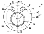
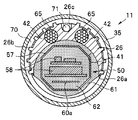
- FIG. 2 is an end view of the distal end portion of the insertion portion
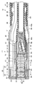
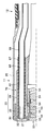
- FIG. 3 is taken along the line III-III in FIG. 4 is a sectional view of the distal end portion taken along line IV-IV of FIG. 2
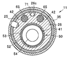
- FIG. 5 is a sectional view of the distal end portion taken along line VV of FIG. 3
- FIG. 7 is a sectional view of the distal end portion along the line VII-VII of FIG. 3
- FIG. 8 is an exploded perspective view showing the main part of the internal structure of the distal end portion. is there.
- an endoscope apparatus 1 includes a long insertion portion 2, an operation portion 3 connected to the proximal end of the insertion portion 2, and a light guide connector 4 connected to a light source device (not shown). And a video connector 5 connected to a video system center (not shown).
- the operation unit 3 and the light guide connector 4 are connected via a flexible cable 6, and the light guide connector 4 and the video connector 5 are connected via a communication cable 7. .
- the insertion portion 2 is provided with a distal end portion 11 mainly composed of a metal member, a bending portion 12, and a rigid tube 13 made of a metal tube such as stainless steel in order from the distal end side.
- the insertion portion 2 is a portion that is inserted into the body, and a cable, a light guide, and the like described later are incorporated therein.
- the operation section 3 is provided with angle levers 14 and 15 for remotely operating the bending section 12, and various switches 16 for operating the light source device, the video system center, and the like.
- the angle levers 14 and 15 are bending operation means capable of operating the bending portion 12 of the insertion portion 2 in four directions, up, down, left and right.
- the endoscope apparatus 1 of this Embodiment is a rigid endoscope apparatus with which most site
- Such an endoscope is not limited to this, and may be, for example, a flexible endoscope device in which the base side is more flexible than the bending portion 12 on the insertion portion 2.
- an illumination lens 21 serving as an illumination window for illumination and a transparent cover member of an optical member serving as an observation window for imaging. 22 are disposed so as to be exposed.
- the endoscope apparatus 1 according to the present embodiment has two illumination lenses 21 on the front surface of the distal end portion 11.
- the distal end portion 11 of the insertion portion 2 has a distal end frame (hard distal end portion) 23.
- the distal end frame 23 includes a first distal end frame 25 disposed on the distal end side (more specifically, the most distal end portion) of the distal end portion 11, and a first distal end frame 25 disposed on the rear stage of the first distal end frame 25.
- the two front end frames 26 are divided.
- the first end frame 25 is configured by a substantially cylindrical member made of a metal material having low thermal conductivity such as stainless steel.
- a front wall portion 30 having a substantially disc shape is formed on the front end side of the first front end frame 25, and an observation hole 31 is opened in the front wall portion 30. Further, a pair of lens holding holes 32 are opened in the front wall portion 30 at a position offset from the observation hole 31, and the illumination lens 21 is fitted and held in these lens holding holes 32.
- the base side of the first tip frame 25 is fitted and fixed to a tip cover 35 having a substantially cylindrical shape made of metal, for example.
- the bending piece 36 located at the forefront among the plurality of bending pieces 36 arranged in the bending portion 12 is connected to the base portion of the tip cover 35.
- the bending pieces 36 adjacent to each other are rotatably connected by a pivot rivet 37.
- the outer periphery of the bending pieces 36 connected in this way is integrally covered with a flexible tube 38 made of fluorine rubber or the like.
- the flexible tube 38 is connected to the proximal end of the distal end cover 35 by a pincushion bonding portion 39 at the distal end outer peripheral portion.
- the second end frame 26 is formed of a substantially cylindrical member made of a metal material having high thermal conductivity such as copper metal or aluminum metal.
- a unit holding hole 41 is opened in the second tip frame 26 at a position corresponding to the observation hole 31 of the first tip frame 25, and the electronic imaging unit 50 is held in the unit holding hole 41.
- a light guide holding hole 42 is opened in the second tip frame 26 at a position corresponding to each lens holding hole 32 of the first tip frame 25, and a light source as a light source is inserted into the light guide holding hole 42. The front end side of the guide bundle 65 is held.
- the electronic imaging unit 50 includes a support frame 51 that fits and holds the transparent cover member 22.
- the support frame 51 is made of a metal member having a substantially cylindrical shape, and is fitted and fixed to the distal end side of the unit holding hole 41 that opens in the second distal end frame 26. Further, inside the unit holding hole 41, a lens holding frame 52 is fitted into the support frame 51, and a unit holding frame 53 is fitted into the lens holding frame 52.
- a plurality of optical lenses 54 are fitted and held on the lens holding frame 52 and the unit holding frame 53, and the objective optical system is configured by the optical lenses 54 and the transparent cover member 22. Further, behind the objective optical system, a cover glass 55 is fitted and held on the unit holding frame 53, and an image sensor 56 made of CCD or CMOS is held on the cover glass 55. Further, an imaging unit exterior frame 57 made of a sheet metal is connected to the base end portion of the unit holding frame 53, and in the imaging unit exterior frame 57, various electronic components 58 attached to the imaging element 56 together with the imaging element 56. Are housed in a modularized state.
- the electronic imaging unit 50 configured as described above is held in a thermally conductive manner with respect to the second distal end frame 26 mainly through the support frame 51, the lens holding frame 52, and the unit holding frame 53. At this time, it is possible to insulate the first metal frame 25, which is an outer layer metal, the front end cover 35, and the image pickup device 56 by making the unit holding frame 53 made of resin. Heat conduction is possible between 52 and the second end frame 26.
- the distal end portion of the signal cable 59 extending from the operation unit 3 side is coupled to the proximal end side of the imaging unit exterior frame 57 and is electrically connected to various electronic components 58.
- a heat transfer tube 60 made of, for example, a copper net tube is provided on the outer periphery of the signal cable 59, and a strip-shaped tropical region 60a formed on the distal end side of the heat transfer tube 60 is connected to the imaging unit exterior. It extends in the frame 57 and faces various electronic components 58.
- a sheath member 60b made of, for example, a heat shrinkable tube is externally mounted on the distal end portion of the signal cable 59 and the outside of the heat transfer tube 60.
- a notch 26a that opens a part of the unit holding hole 41 is formed on the base side of the second end frame 26 (see FIG. 8), and the unit holding hole 41 is bonded to the inside through the notch 26a.
- Agent 61 is filled.
- the inside of the imaging unit exterior frame 57 is also filled with the adhesive 62, whereby the electronic imaging unit 50 is liquid-tightly sealed in the second tip frame 26, and these adhesives are interposed therebetween.
- heat conduction is possible with respect to the second end frame 26.
- a heat insulating layer 70 is provided.
- each light guide bundle 65 is inserted into and fixed to each light guide holding hole 42 at the tip side.
- the heat generated at the front end side of the light guide bundle 65 is basically diffused to the second front end frame 26 through the light guide holding hole 42, but the cooling performance of the light guide bundle 65 is ensured.
- a heat transfer tube 66 made of, for example, a copper mesh tube is provided on the outer periphery of each light guide bundle 65. It is desirable to be provided. Further, on the distal end side of the light guide bundle 65, it is desirable that a tubular member 67 made of heat-insulating resin or silicon is provided on the outer periphery of the heat transfer tube 66.
- the second distal end frame 26 holding the electronic imaging unit 50 and the light guide bundle 65 in this way is fitted inside the distal end cover 35 on the base side of the first distal end frame 25, and via a fixing pin (not shown). It is fixed to the first tip frame 25.
- the second tip frame 26 is supported through the first tip frame 25 so as not to be exposed on the outer surface of the tip portion 11.
- the fixing pins serve both for fixing the electronic imaging unit 50 and the second tip frame, the number of fixing pins can be reduced, and a larger volume of the tip frame 26 can be secured.
- the groove 26 c is formed.
- a hole into which the heat transfer member 71 can be inserted may be provided in the distal end frame 26. Further, in order to promote heat transfer between the heat transfer member 71 and the second tip frame 26, it is desirable to form the joining distance as long as possible.
- the positioning between the observation hole 31 and the lens holding hole 32 on the first front end frame 25 and the unit holding hole 41 and the light guide holding hole 42 on the second front end frame 26 is performed.
- the transparent cover member 22 located at the tip of the electronic imaging unit 50 is exposed to the outside through the observation hole 31 and the tip side of each light guide bundle 65 is optically connected to the illumination lens 21.
- the second tip frame 26 is held in a state where it does not contact the tip cover 35, whereby a heat insulating layer 70 made of an air layer is formed between the second tip frame 26 and the tip cover 35.
- a heat insulating layer 70 made of an air layer is formed between the second tip frame 26 and the tip cover 35.
- a plurality of heat dissipating fins 26b exposed to the heat insulating layer 70 (air layer) are provided on the outer periphery on the base side of the second tip frame 26 (see FIGS. 7 and 8).
- the heat insulating layer 70 may be formed of a heat insulating member or the like instead of the air layer.
- the tip end side of the heat transfer member 71 that transfers the heat of the second tip frame 26 to the base side of the insertion portion 2 is fixed to a part of the outer peripheral surface of the second tip frame 26.
- a well-known insulated wire can be adopted as the heat transfer member 71, and the thermal connection of the heat transfer member 71 to the second tip frame 26 is, for example, A part of the tip side exposed from the outer sheath of the insulated wire is disposed in a concave groove 26c formed in a part on the outer peripheral surface of the second tip frame 26, and is fixed via an adhesive, solder, or the like. Is realized.
- the heat transfer member 71 is fixed to the second distal end frame 26 without being in contact with the distal end cover 35. Further, the heat transfer member 71 may not be an insulated wire because of thermal conductivity, but it is desirable to cover the wire to protect the wire during bending and to prevent interference with other built-in components.
- the number of members is not limited to one, and a plurality of members may be provided, or the shape may be branched on the layout in the bending portion and the insertion portion.
- the heat transfer member 71 is composed of a silver solder wire, a copper tin wire, a copper wire, or the like.
- the distal end frame 23 that holds the light guide bundle 65 and the electronic imaging unit 50 in the distal end portion 11 includes the first distal end frame 25 disposed on the distal end side of the distal end portion 11 and the distal end.
- the second end frame 26 that is supported through the first front end frame 25 and is not exposed to the outer surface of the portion 11 and that holds the light guide bundle 65 and the electronic imaging unit 50 is divided and formed. Since the thermal conductivity of the distal end frame 26 is made of a member higher than that of the first distal end frame 25, the imaging element 56 can be protected from thermal damage without increasing the outer surface temperature of the distal end portion 11.
- the second tip frame 26 is formed of a member having high thermal conductivity, and the light guide bundle 65 and the electronic imaging unit 50 are held on the second tip frame 26, whereby the light guide bundle 65 and the electronic imaging unit are held.
- the heat generated in the unit 50 can be diffused to the second end frame 26 side to protect the image sensor 56 from heat damage.
- the second tip frame 26 is arranged so as not to be exposed on the outer surface of the tip portion 11, and the tip portion 11 is interposed via the first tip frame 25 having a lower thermal conductivity than the second tip frame 26. By supporting inward, it can suppress that the heat
- the heat transfer member 71 extending to the proximal end side of the insertion portion 2 to at least a part of the second distal end frame 26, the heat diffused in the second distal end frame 26 is Heat can be radiated suitably through the heat transfer member 71. Therefore, even when the light guide bundle 65 and the electronic imaging unit 50 generate a large amount of heat, the imaging element 56 can be more accurately protected from heat damage and an increase in the outer surface temperature of the distal end portion 11 can be suppressed. As shown in FIGS. 5 to 8, it is better to provide the heat transfer member 71 between the light guide bundles 65 and at a position opposite to the imaging unit 50 so that the balance of the built-in objects in the bending portion is good. Can behave smoothly.
- the heat insulating layer 70 between the tip cover 35 constituting the outer surface of the tip portion 11 and the second tip frame 26, an increase in the outer surface temperature of the tip portion 11 can be suppressed more accurately. Can do.
- the heat insulating layer 70 is formed of an air layer, heat transfer from the second tip frame 26 to the outer surface of the tip portion 11 can be suppressed with a simple configuration without complicating the structure. Can do.
- the heat dissipating fins 26b exposed to the heat insulating layer 70 (air layer) are provided on the base side of the second tip frame 26, the heat of the second tip frame 26 is efficiently diffused into the air layer, and imaging is performed.
- the element 56 can be more suitably protected from heat damage.
- the loss of illumination light is mainly caused by irregular reflection of light at a connection portion with the illumination lens 21 or the like. And much of the light irregularly reflected in this way is converted into heat. Therefore, in order to suppress the heat generated in the light guide bundle 65, it is desirable to improve the light transmission efficiency between the light guide bundle 65 and the illumination lens 21.
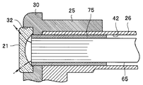
- the first to fourth modified examples shown in FIGS. 9 to 12 are for explaining the configuration for reducing the loss of illumination light, and FIGS. 9 to 12 show the main part of the tip part according to each modified example. It is sectional drawing.
- the first modification shown in FIG. 9 is for adjusting the relative position of the light guide bundle 65 with respect to the illumination lens 21, thereby precisely matching these optical axes and reducing light loss. is there.
- a base 75 is fixed to the front end side of the light guide bundle 65, and the light guide bundle 65 is loosely fitted into the light guide holding hole 42 via the base 75.
- the light guide holding hole 42 communicates with a spring holding hole 76 that opens in the second tip frame 26 and a screw hole 77 that passes through the first and second tip frames 25 and 26. Yes.
- a spring 79 that urges the peripheral surface of the base 75 in a predetermined direction via a pressing member 78 is accommodated in the spring holding hole 76.
- a screw member 80 for pressing the peripheral surface of the base 75 against the urging force of the spring 79 is screwed into the screw hole 77.
- the relative position (optical axis or the like) of the light guide bundle 65 with respect to the illumination lens 21 can be finely adjusted by adjusting the screwing amount of the screw member 80 with respect to the screw hole 77. Yes.
- the second and third modified examples shown in FIGS. 10 and 11 are for reducing light loss by bringing the front end surface of the light guide bundle 65 into close contact with the back surface of the illumination lens 21. is there.
- the tip surface of the light guide bundle 65 is formed in a shape matching the lens curved surface of the illumination lens 21 by polishing or the like. Yes.
- the back surface of the illumination lens 21 is formed in a plane that coincides with the front end surface of the light guide bundle 65.
- the light guide bundle 65 can be brought into close contact with the illumination lens 21, and light loss can be reduced.
- the fourth modification shown in FIG. 12 is for reducing the loss of light by optimizing the relationship between the curvature of the illumination lens 21 and the numerical aperture of the strands constituting the light guide bundle 65. Is.
- the lens curved surface of the illumination lens 21 is designed based on the relationship with the numerical aperture of the strands of the light guide bundle 65. It is designed so that the light incident on the rear surface of the lens does not exit from the side surface (circumferential surface) of the illumination lens 21 through refraction and the like.
- the light incident on the back side of the illumination lens 21 from the light guide bundle 65 can be efficiently emitted from the front end side of the illumination lens 21, and light loss can be reduced.
Landscapes
- Health & Medical Sciences (AREA)
- Life Sciences & Earth Sciences (AREA)
- Surgery (AREA)
- Biomedical Technology (AREA)
- Medical Informatics (AREA)
- Optics & Photonics (AREA)
- Pathology (AREA)
- Radiology & Medical Imaging (AREA)
- Biophysics (AREA)
- Engineering & Computer Science (AREA)
- Physics & Mathematics (AREA)
- Heart & Thoracic Surgery (AREA)
- Nuclear Medicine, Radiotherapy & Molecular Imaging (AREA)
- Molecular Biology (AREA)
- Animal Behavior & Ethology (AREA)
- General Health & Medical Sciences (AREA)
- Public Health (AREA)
- Veterinary Medicine (AREA)
- Endoscopes (AREA)
- Instruments For Viewing The Inside Of Hollow Bodies (AREA)
- Studio Devices (AREA)
Abstract
ライトガイドバンドル65及び電子撮像ユニット50を先端部11内に保持する先端枠23を、先端部11の先端側に配置された第1の先端枠25と、先端部11の外表面に露出しない状態で第1の先端枠25を介して支持され、ライトガイドバンドル65及び電子撮像ユニット50を保持する第2の先端枠26と、に分割形成し、第2の先端枠26の熱伝導率を第1の先端枠25よりも高い部材で構成することにより、先端部11の外表面温度を上昇させることなく、撮像素子56を熱害から保護する。
Description
本発明は、挿入部の先端部に電子撮像ユニットを備えた内視鏡装置に関する。
従来、医療分野等においては、生体の体内等の目視では観察が困難な被検体内部の箇所を観察するため、挿入部の先端部に光学像を観察するための電子撮像ユニットを備えた内視鏡が利用されている。電子撮像ユニットは、例えば、対物レンズと、対物レンズの結像面に配設されたCCD(電荷結合素子)やCMOS(相補型金属酸化膜半導体)センサ等の撮像素子を具備してなる。
近年、この種の内視鏡装置では、撮像素子の高性能化や、照明光の高出力化による撮像画像の高精細化が進められている。その一方で、例えば、撮像素子を高性能化した場合、当該撮像素子やこれに付随する各種電子部品等からの発熱量が増加する。また、照明光を高出力化した場合、照明光学系の内部で乱反射等する光の光量が増加し、乱反射した光の多くは、先端部内において熱に変換される。そして、これらの熱が先端部内に残留すると、撮像素子に所謂温度ノイズが発生して画像が劣化する虞がある。
これに対し、例えば、日本国特開2001-299677号公報には、機械的耐久性及び化学的耐久性(耐薬品性)に優れたステンレス材料により形性された第1の外ケース内に、熱伝導性に優れたステンレス材料により形成された保持部材を収納し、保持部材の内部空間に電子撮像ユニット(受光レンズ及びCCD等)を挿入するとともに、保持部材の前端面において受光レンズを取り囲む位置に光源として複数のLEDを配設した技術が開示されている。この特許文献1の技術では、保持部材を熱伝導性の高い材料により形成するとともに、保持部材の外周面が薄肉の第1の外ケースの内周面に直接当接させることにより、複数のLEDで発生した熱が保持部材を伝わり、第1の外ケースから外部に効率的に放出される。
しかしながら、上述の日本国特開2001-299677号公報に開示された技術のように先端部の外部に熱を放出した場合、先端部の外表面温度の上昇を招く虞がある。特に、撮像素子の高性能化や照明光の高出力化が進められた内視鏡においては、発生する熱量が大きいため、先端部の外表面温度の上昇を抑制する観点から、外部に放出可能な熱量には限界がある。
本発明は上記事情に鑑みてなされたもので、先端部の外表面温度を上昇させることなく、撮像素子を熱害から保護することができる内視鏡装置を提供することを目的とする。
本発明の一態様による内視鏡装置は、挿入部の先端部内に、光源と電子撮像ユニットとが先端枠を介して保持された内視鏡装置であって、前記先端枠は、前記先端部の先端側に配設された第1の先端枠と、前記先端部の外表面に露出しない状態に配置されて前記第1の先端枠を介して支持され、前記光源及び前記電子撮像ユニットを保持する第2の先端枠と、を備え、前記第2の先端枠の熱伝導率を前記第1の先端枠の熱伝導率よりも高い部材で構成したものである。
以下、図面を参照して本発明の形態を説明する。図面は本発明の一実施形態に係わり、図1は内視鏡装置の全体構成を示す斜視図、図2は挿入部の先端部の端面図、図3は図2のIII-III線に沿った先端部の断面図、図4は図2のIV-IV線に沿った先端部の断面図、図5は図3のV-V線に沿った先端部の断面図、図6は図3のVI-VI線に沿った先端部の断面図、図7は図3のVIIーVII線に沿った先端部の断面図、図8は先端部の内部構造の要部を示す分解斜視図である。
図1に示すように、内視鏡装置1は、長尺な挿入部2と、この挿入部2の基端と連設された操作部3と、図示しない光源装置に接続するライトガイドコネクタ4と、図示しないビデオシステムセンターに接続するビデオコネクタ5と、を有して主に構成されている。なお、内視鏡装置1は、操作部3とライトガイドコネクタ4とが軟性ケーブル6を介して接続されており、ライトガイドコネクタ4とビデオコネクタ5とが通信ケーブル7を介して接続されている。
挿入部2には、主に金属製部材によって構成された先端部11、湾曲部12、及びステンレス等の金属管の硬性管13が先端側から順に連設されている。この挿入部2は、体内に挿入する部分となっており、内部に後述するケーブル、及びライトガイド等が組み込まれている。
操作部3には、湾曲部12を遠隔操作するアングルレバー14,15、及び光源装置、ビデオシステムセンターなどを操作するための各種スイッチ16が備えられている。アングルレバー14,15は、挿入部2の湾曲部12を上下左右の4方向に操作可能な湾曲操作手段である。なお、本実施の形態の内視鏡装置1は、例えば、湾曲部12を除く挿入部2上の大部分の部位が硬質となっている硬性内視鏡装置であるが、本発明が適用可能な内視鏡は、これに限定されるものではなく、例えば、挿入部2上の湾曲部12よりも基部側が可撓性を有する軟性内視鏡装置であってもよい。
次に、図2乃至図8を参照して、内視鏡装置1の挿入部2の先端内部構成について詳しく説明する。
図2に示すように、内視鏡装置1の先端部11の端面(先端面)には、照明用の照明窓となる照明レンズ21と、撮像用の観察窓となる光学部材の透明カバー部材22と、が露出するように配設されている。なお、本実施の形態の内視鏡装置1は、先端部11の前面に2つの照明レンズ21を有している。
図2に示すように、内視鏡装置1の先端部11の端面(先端面)には、照明用の照明窓となる照明レンズ21と、撮像用の観察窓となる光学部材の透明カバー部材22と、が露出するように配設されている。なお、本実施の形態の内視鏡装置1は、先端部11の前面に2つの照明レンズ21を有している。
具体的に説明すると、図3乃至図8に示すように、挿入部2の先端部11は、先端枠(先端硬質部)23を有している。この先端枠23は、先端部11の先端側(より具体的には、最先端部)に配設された第1の先端枠25と、第1の先端枠25の後段に配設された第2の先端枠26とで分割形成されている。
第1の先端枠25は、例えば、ステンレス系金属等の熱伝導性の低い金属材料からなる略円筒状の部材で構成されている。
この第1の先端枠25の先端側には、略円板形状をなす前壁部30が形成され、この前壁部30には観察孔31が開口されている。さらに、前壁部30には、観察孔31からオフセットした位置に、一対のレンズ保持孔32が開口され、これらレンズ保持孔32には照明レンズ21がそれぞれ嵌合保持されている。一方、第1の先端枠25の基部側は、例えば、金属製の略円筒形状をなす先端カバー35に内嵌固定されている。
ここで、先端カバー35の基部には、湾曲部12内に配列された複数の湾曲駒36のうち、最先端に位置する湾曲駒36が連結されている。これら湾曲駒36は互いに隣接するもの同士が枢軸リベット37によって回動自在に連結されている。このように連結された湾曲駒36の外周は、フッ素ゴム等から形成された軟性チューブ38によって一体的に覆われている。この軟性チューブ38は、先端外周部が糸巻接着部39によって、先端カバー35の基端に接続されている。
第2の先端枠26は、例えば、銅系金属或いはアルミニウム系金属等の熱伝導性の高い金属材料からなる略円柱状の部材で構成されている。
この第2の先端枠26には、第1の先端枠25の観察孔31に対応する位置に、ユニット保持孔41が開口され、このユニット保持孔41には電子撮像ユニット50が保持されている。また、第2の先端枠26には、第1の先端枠25の各レンズ保持孔32に対応する位置に、ライトガイド保持孔42が開口され、このライトガイド保持孔42には光源としてのライトガイドバンドル65の先端側が保持されている。
具体的に説明すると、図3に示すように、電子撮像ユニット50は、透明カバー部材22を嵌合保持する支持枠51を有する。この支持枠51は、略円筒形状をなす金属製の部材で構成され、第2の先端枠26に開口するユニット保持孔41の先端側に嵌挿固定されている。また、ユニット保持孔41の内部において、支持枠51には、レンズ保持枠52が内嵌され、さらに、レンズ保持枠52にはユニット保持枠53が外嵌されている。
これらレンズ保持枠52及びユニット保持枠53には複数の光学レンズ54が嵌合保持され、これら光学レンズ54及び透明カバー部材22によって対物光学系が構成されている。また、対物光学系の背後において、ユニット保持枠53にはカバーガラス55が嵌合保持され、このカバーガラス55には、CCD或いはCMOS等からなる撮像素子56が保持されている。さらに、ユニット保持枠53基端部には、板金製の撮像部外装枠57が連結され、この撮像部外装枠57内には、撮像素子56とともに、当該撮像素子56に付随する各種電子部品58がモジュール化された状態で収容されている。
そして、このように構成された電子撮像ユニット50は、主として支持枠51、レンズ保持枠52、及びユニット保持枠53を通じて、第2の先端枠26に対し、熱伝導可能に保持されている。なお、このとき、ユニット保持枠53を樹脂製にすることで外層金属である第1の金属枠25、先端カバー35と撮像素子56を絶縁することができるが、このときにおいても、レンズ保持枠52と第2の先端枠26との間で熱伝導可能となる。
ここで、撮像部外装枠57の基端側には、操作部3側から延在する信号ケーブル59の先端部が連結され、各種電子部品58と電気的に接続されている。本実施形態において、信号ケーブル59の外周には、例えば、銅製の網管等からなる伝熱管60が設けられ、この伝熱管60の先端側に形成された短冊状の伝熱帯60aが、撮像部外装枠57内に延設されて各種電子部品58の近傍に臨まされている。信号ケーブル59の先端部及び伝熱管60の外側には、例えば、熱収縮チューブからなる外套部材60bが外装される。
また、第2の先端枠26の基部側にはユニット保持孔41の一部を開放する切欠部26aが形成され(図8参照)、この切欠部26aを通じて、ユニット保持孔41の内部には接着剤61が充填されている。さらに、撮像部外装枠57の内部にも接着剤62が充填され、これらにより、電子撮像ユニット50は、第2の先端枠26内において、液密に封止されており、これら接着剤を介しても、第2の先端枠26に対して熱伝導可能になっている。なお、切欠部26aに電子撮像ユニット50の外径が大きい部分を配置することで、内視鏡挿入部外径を細径化したり、挿入部外径の細径化を確保したまま、後述する断熱層70を設けられる。
図4に示すように、各ライトガイドバンドル65は、先端側が各ライトガイド保持孔42内に嵌挿固定されている。
ここで、ライトガイドバンドル65の先端側で発生した熱は、基本的にはライトガイド保持孔42を通じて第2の先端枠26に拡散されるものであるが、ライトガイドバンドル65の冷却性能を確保しつつ、第2の先端枠26に拡散される熱量を抑制するため、例えば、図4に示すように、各ライトガイドバンドル65の外周には、例えば、銅製の網管等からなる伝熱管66が設けられていることが望ましい。さらに、ライトガイドバンドル65の先端側において、伝熱管66の外周には、断熱性を有する樹脂或いはシリコン等からなる管状部材67が設けられていることが望ましい。
このように電子撮像ユニット50及びライトガイドバンドル65を保持した第2の先端枠26は、先端カバー35内において、第1の先端枠25の基部側に内嵌され、図示しない固定ピンを介して第1の先端枠25に固定されている。これにより、第2の先端枠26は、第1の先端枠25を介して、先端部11の外表面に露出しない状態で支持されている。このとき、固定ピンは、電子撮像ユニット50と第2の先端枠の固定とを兼用すると、固定ピンの数を減らし、先端枠26の体積をより多く確保できる。図3に示す例では凹溝26cとして形成しているが、先端枠26に対して伝熱部材71を挿入できる穴を設けても良い。また、伝熱部材71と第2の先端枠26の熱伝達を促進させるため、接合距離をできるだけ長く形成する方が望ましい。
その際、第1の先端枠25上の観察孔31及びレンズ保持孔32と、第2の先端枠26上のユニット保持孔41及びライトガイド保持孔42との間の位置決めがなされることにより、電子撮像ユニット50の先端に位置する透明カバー部材22が観察孔31を通じて外部に露呈されるとともに、各ライトガイドバンドル65の先端側が照明レンズ21に対して光学的に連結される。
また、第2の先端枠26は、先端カバー35に当接しない状態で保持され、これにより、第2の先端枠26と先端カバー35との間には、空気層からなる断熱層70が形成されている(図3,6,7参照)。また、本実施形態において、第2の先端枠26の基部側外周には、断熱層70(空気層)に露呈する複数の放熱フィン26bが設けられている(図7,8参照)なお、図示しないが、断熱層70は、空気層に代えて、断熱部材等によって構成することも可能である。
また、第2の先端枠26の外周面上の一部には、当該第2の先端枠26の熱を挿入部2の基部側に伝達する伝熱部材71の先端側が固着されている。図3に示すように、この伝熱部材71としては、例えば、周知の絶縁電線を採用することが可能であり、この伝熱部材71の第2の先端枠26に対する熱的な接続は、例えば、絶縁電線の外皮から露出させた先端側の一部を、第2の先端枠26の外周面上の一部に形成した凹溝26c内に配置し、接着剤や半田等を介して固定することにより実現される。この場合において、伝熱部材71は、先端カバー35に当接しない状態で第2の先端枠26に固着されることが望ましい。また、伝熱部材71は、熱伝導性のため、絶縁電線でなくてもよいが、湾曲時の電線の保護、他の内蔵物との干渉防止のため、被覆させることが望ましいし、伝熱部材は1本に限らず複数具備されてもよいし、湾曲部、挿入部内のレイアウト上分岐した形状となってもよい。伝熱部材71は、銀ろう線、銅すず線、銅線などで構成されている。
このような実施形態によれば、ライトガイドバンドル65及び電子撮像ユニット50を先端部11内に保持する先端枠23を、先端部11の先端側に配置された第1の先端枠25と、先端部11の外表面に露出しない状態で第1の先端枠25を介して支持され、ライトガイドバンドル65及び電子撮像ユニット50を保持する第2の先端枠26と、に分割形成し、第2の先端枠26の熱伝導率を第1の先端枠25よりも高い部材で構成したことにより、先端部11の外表面温度を上昇させることなく、撮像素子56を熱害から保護することができる。
すなわち、第2の先端枠26を熱伝導率の高い部材で構成し、当該第2の先端枠26にライトガイドバンドル65及び電子撮像ユニット50を保持することにより、これらライトガイドバンドル65及び電子撮像ユニット50で発生した熱を第2の先端枠26側に拡散して、撮像素子56を熱害から保護することができる。しかも、第2の先端枠26を先端部11の外表面に露出しない状態に配置して、当該第2の先端枠26よりも熱伝導率の低い第1の先端枠25を介して先端部11内に支持することにより、第2の先端枠26に拡散された熱が先端部11の外表面側に拡散することを抑制することができる。その際、第2の先端枠26の先端面が突き当てられる第1の先端枠25前壁部30を厚肉に形成すれば、第2の先端枠26側からの熱が第1の先端枠25を通じて外表面に拡散することを的確に抑制することができる。
この場合において、第2の先端枠26の少なくとも一部に、挿入部2の基端側に延在する伝熱部材71を固着することにより、第2の先端枠26に拡散された熱を、伝熱部材71を介して好適に放熱することができる。従って、ライトガイドバンドル65及び電子撮像ユニット50の発熱量が多い場合にも、より的確に撮像素子56を熱害から保護するとともに先端部11の外表面温度の上昇を抑制することができる。なお、図5~図8に示すように、伝熱部材71をライトガイドバンドル65の間且つ撮像ユニット50と相反する位置に設けた方が湾曲部内の内蔵物のバランスがよく、湾曲時に内蔵物をスムーズに挙動することができる。
また、先端部11の外表面を構成する先端カバー35と第2の先端枠26との間に断熱層70を介在させることにより、先端部11の外表面温度の上昇をより的確に抑制することができる。この場合、特に、断熱層70を空気層で構成すれば、構造を複雑化することなく簡単な構成で、第2の先端枠26から先端部11の外表面への熱の伝達を抑制することができる。しかも、第2の先端枠26の基部側に、断熱層70(空気層)に露呈する放熱フィン26bを設ければ、第2の先端枠26の熱を効率よく空気層に拡散して、撮像素子56をより好適に熱害から保護することができる。
ところで、ライトガイドバンドル65等を光源とする場合において、照明光の損失は、主に、照明レンズ21との接続部分における光の乱反射等によって発生する。そして、このように乱反射等された光の多くは熱に変換される。従って、ライトガイドバンドル65で発生する熱を抑制するためには、当該ライトガイドバンドル65と照明レンズ21との間の光の伝達効率を向上することが望ましい。図9乃至図12に示す第1~第4の変形例は、照明光の損失を低減するための構成について説明するものであり、図9乃至図12は各変形例に係る先端部の要部断面図である。
図9に示す第1の変形例は、照明レンズ21に対するライトガイドバンドル65の相対位置を調整可能とすることにより、これらの光軸を精密に一致させ、光の損失を低減するためのものである。この第1の変形例において、ライトガイドバンドル65の先端側には口金75が固設され、ライトガイドバンドル65は、口金75を介して、ライトガイド保持孔42内に遊嵌されている。
また、ライトガイド保持孔42には、第2の先端枠26に開口するスプリング保持穴76が連通されるとともに、第1,第2の先端枠25,26を貫通するネジ孔77が連通されている。スプリング保持穴76内には、押圧部材78を介して口金75の周面を所定方向に付勢するスプリング79が収容されている。また、ネジ孔77には、スプリング79の付勢力に抗して口金75の周面を押圧するためのネジ部材80が螺合されている。そして、本変形例では、ネジ孔77に対するネジ部材80の螺合量を調整することにより、照明レンズ21に対するライトガイドバンドル65の相対位置(光軸等)を微調整することが可能となっている。
次に、図10,11に示す第2,第3の変形例は、照明レンズ21の背面に対してライトガイドバンドル65の先端面を密着させることにより、光の損失を低減するためのものである。
ライトガイドバンドル65を密着させるための構成として、図10に示す第2の変形例では、ライトガイドバンドル65の先端面が、研磨等により、照明レンズ21のレンズ曲面と一致する形状に形成されている。
また、図11に示す第3の変形例では、照明レンズ21の背面が、ライトガイドバンドル65の先端面と一致する平面に形成されている。
これらの構成により、第2,第3の変形例では、照明レンズ21に対してライトガイドバンドル65を密着させることができ、光の損失を低減することか可能となる。
次に、図12に示す第4の変形例は、照明レンズ21の曲率とライトガイドバンドル65を構成する素線の開口数との関係を最適化することにより、光の損失を低減するためのものである。
図12に示すように、本変形例において、照明レンズ21のレンズ曲面は、ライトガイドバンドル65の素線の開口数との関係に基づいて設計され、これにより、ライトガイドバンドル65から照明レンズ21の背面に入射した光が、屈折等を経て照明レンズ21の側面(周面)から出射しないよう設計されている。
このような構成により、ライトガイドバンドル65から照明レンズ21の背面側に入射した光を照明レンズ21の先端面側から効率よく出射させることができ、光の損失を低減することができる。
本出願は、2011年7月19日に日本国に出願された特願2011-158243号を優先権主張の基礎として出願するものであり、上記の内容は、本願明細書、請求の範囲、および図面に引用されたものである。
Claims (9)
- 挿入部の先端部内に、光源と電子撮像ユニットとが先端枠を介して保持された内視鏡装置であって、
前記先端枠は、前記先端部の先端側に配設された第1の先端枠と、
前記先端部の外表面に露出しない状態に配置されて前記第1の先端枠を介して支持され、前記光源及び前記電子撮像ユニットを保持する第2の先端枠と、を備え、
前記第2の先端枠の熱伝導率を前記第1の先端枠の熱伝導率よりも高い部材で構成したことを特徴とする内視鏡装置。 - 前記第2の先端枠の少なくとも一部に固着され、当該第2の先端枠の熱を前記挿入部の基部側に伝達する伝熱部材を有することを特徴とする請求項1記載の内視鏡装置。
- 前記第1の先端枠の基部側に外嵌する先端カバーと、
前記先端カバーと前記第2の先端枠との間に介装された断熱層と、を有することを特徴とする請求項1記載の内視鏡装置。 - 前記先端カバーに当接しない状態で前記第2の先端枠の少なくとも一部に固着され、当該第2の先端枠の熱を前記挿入部の基部側に伝達する伝熱部材を有することを特徴とする請求項3記載の内視鏡装置。
- 前記断熱層は空気層であることを特徴とする請求項3記載の内視鏡装置。
- 前記第2の先端枠は、前記空気層に露呈する放熱フィンを有することを特徴とする請求項5記載の内視鏡装置。
- 前記断熱層は空気層であることを特徴とする請求項4記載の内視鏡装置。
- 前記第2の先端枠は、前記空気層に露呈する放熱フィンを有することを特徴とする請求項7記載の内視鏡装置。
- 前記第1の先端枠は、ステンレス系金属からなり、前記第2の先端枠は、銅系金属或いはアルミニウム系金属からなることを特徴とする請求項1記載の内視鏡装置。
Priority Applications (4)
| Application Number | Priority Date | Filing Date | Title |
|---|---|---|---|
| EP12814558.8A EP2676594B1 (en) | 2011-07-19 | 2012-04-06 | Endoscope apparatus |
| CN201280015537.4A CN103476319B (zh) | 2011-07-19 | 2012-04-06 | 内窥镜装置 |
| JP2013502934A JP5341279B2 (ja) | 2011-07-19 | 2012-04-06 | 内視鏡装置 |
| US13/746,373 US9072450B2 (en) | 2011-07-19 | 2013-01-22 | Endoscope apparatus |
Applications Claiming Priority (2)
| Application Number | Priority Date | Filing Date | Title |
|---|---|---|---|
| JP2011158243 | 2011-07-19 | ||
| JP2011-158243 | 2011-07-19 |
Related Child Applications (1)
| Application Number | Title | Priority Date | Filing Date |
|---|---|---|---|
| US13/746,373 Continuation US9072450B2 (en) | 2011-07-19 | 2013-01-22 | Endoscope apparatus |
Publications (1)
| Publication Number | Publication Date |
|---|---|
| WO2013011721A1 true WO2013011721A1 (ja) | 2013-01-24 |
Family
ID=47557915
Family Applications (1)
| Application Number | Title | Priority Date | Filing Date |
|---|---|---|---|
| PCT/JP2012/059479 Ceased WO2013011721A1 (ja) | 2011-07-19 | 2012-04-06 | 内視鏡装置 |
Country Status (5)
| Country | Link |
|---|---|
| US (1) | US9072450B2 (ja) |
| EP (1) | EP2676594B1 (ja) |
| JP (1) | JP5341279B2 (ja) |
| CN (1) | CN103476319B (ja) |
| WO (1) | WO2013011721A1 (ja) |
Cited By (1)
| Publication number | Priority date | Publication date | Assignee | Title |
|---|---|---|---|---|
| JP2022166635A (ja) * | 2021-04-21 | 2022-11-02 | 富士フイルム株式会社 | 内視鏡カメラヘッド |
Families Citing this family (13)
| Publication number | Priority date | Publication date | Assignee | Title |
|---|---|---|---|---|
| US10039440B2 (en) * | 2012-06-11 | 2018-08-07 | Intuitive Surgical Operations, Inc. | Systems and methods for cleaning a minimally invasive instrument |
| JP5639313B2 (ja) * | 2012-07-19 | 2014-12-10 | オリンパスメディカルシステムズ株式会社 | 内視鏡の挿入部の先端硬質部及び、この先端硬質部を用いた内視鏡 |
| JP5836304B2 (ja) * | 2013-03-28 | 2015-12-24 | 株式会社フジクラ | 気管チューブ |
| JP6109462B1 (ja) * | 2015-06-18 | 2017-04-05 | オリンパス株式会社 | 内視鏡 |
| KR101889914B1 (ko) * | 2016-12-06 | 2018-08-21 | 해성옵틱스(주) | 초소형 내시경 카메라 모듈 및 이를 구비하는 초소형 내시경 |
| JP2018138111A (ja) * | 2017-02-24 | 2018-09-06 | オリンパス株式会社 | Led式先端光学アダプタ |
| WO2020188687A1 (ja) * | 2019-03-18 | 2020-09-24 | オリンパス株式会社 | 内視鏡の先端枠及び先端ユニット |
| DE102019129815B4 (de) * | 2019-11-05 | 2021-11-04 | Karl Storz Se & Co. Kg | Kühlvorrichtung für ein Endoskop oder Exoskop |
| WO2021238239A1 (zh) * | 2020-05-25 | 2021-12-02 | 卓外(上海)医疗电子科技有限公司 | 内窥镜插入部散热结构 |
| CN113712486B (zh) * | 2020-05-25 | 2025-08-22 | 卓外(上海)医疗电子科技有限公司 | 内窥镜插入部散热结构 |
| CN111887798B (zh) * | 2020-08-31 | 2025-06-17 | 深圳市精锋医疗科技股份有限公司 | 电子内窥镜以及手术机器人 |
| TWI843897B (zh) * | 2020-09-30 | 2024-06-01 | 模里西斯商鴻建裕醫療投資股份有限公司 | 可拋整合型內視鏡 |
| TWI747606B (zh) * | 2020-11-11 | 2021-11-21 | 群光電子股份有限公司 | 內視鏡裝置 |
Citations (12)
| Publication number | Priority date | Publication date | Assignee | Title |
|---|---|---|---|---|
| JP2000287913A (ja) * | 1999-04-09 | 2000-10-17 | Olympus Optical Co Ltd | 内視鏡装置 |
| JP2001046317A (ja) * | 1999-08-06 | 2001-02-20 | Olympus Optical Co Ltd | 内視鏡 |
| JP2001299677A (ja) | 2000-04-26 | 2001-10-30 | Keyence Corp | 内視鏡 |
| JP2002177197A (ja) * | 2000-12-14 | 2002-06-25 | Asahi Optical Co Ltd | 内視鏡の先端部 |
| JP2003153852A (ja) * | 2001-11-22 | 2003-05-27 | Olympus Optical Co Ltd | 電子内視鏡 |
| WO2006046559A1 (ja) * | 2004-10-25 | 2006-05-04 | Olympus Corporation | 内視鏡装置 |
| JP2007014488A (ja) * | 2005-07-06 | 2007-01-25 | Olympus Corp | 内視鏡 |
| JP2008155016A (ja) * | 2007-12-03 | 2008-07-10 | Olympus Corp | 電子内視鏡 |
| JP2009022636A (ja) * | 2007-07-23 | 2009-02-05 | Olympus Corp | 内視鏡 |
| JP2009247620A (ja) * | 2008-04-07 | 2009-10-29 | Olympus Corp | 内視鏡装置、アダプタ |
| JP2010187902A (ja) * | 2009-02-18 | 2010-09-02 | Fujifilm Corp | 内視鏡 |
| JP2011072424A (ja) * | 2009-09-29 | 2011-04-14 | Fujifilm Corp | 投光ユニット、及びこれを搭載した医療機器、並びに内視鏡装置 |
Family Cites Families (6)
| Publication number | Priority date | Publication date | Assignee | Title |
|---|---|---|---|---|
| GB1070317A (en) * | 1963-08-29 | 1967-06-01 | Armco Steel Corp | Stainless steel |
| DE20321839U1 (de) * | 2002-04-12 | 2010-12-30 | Olympus Corporation | Inzisionsvorrichtung zur Verwendung mit einem Endoskop |
| US8435173B2 (en) * | 2003-10-06 | 2013-05-07 | Olympus Corporation | Endoscope |
| JP4418202B2 (ja) * | 2003-10-06 | 2010-02-17 | オリンパス株式会社 | 内視鏡 |
| WO2010055753A1 (ja) * | 2008-11-11 | 2010-05-20 | オリンパスメディカルシステムズ株式会社 | 撮像装置および内視鏡 |
| JP2010263946A (ja) * | 2009-05-12 | 2010-11-25 | Fujifilm Corp | 内視鏡 |
-
2012
- 2012-04-06 EP EP12814558.8A patent/EP2676594B1/en not_active Not-in-force
- 2012-04-06 CN CN201280015537.4A patent/CN103476319B/zh active Active
- 2012-04-06 WO PCT/JP2012/059479 patent/WO2013011721A1/ja not_active Ceased
- 2012-04-06 JP JP2013502934A patent/JP5341279B2/ja active Active
-
2013
- 2013-01-22 US US13/746,373 patent/US9072450B2/en active Active
Patent Citations (12)
| Publication number | Priority date | Publication date | Assignee | Title |
|---|---|---|---|---|
| JP2000287913A (ja) * | 1999-04-09 | 2000-10-17 | Olympus Optical Co Ltd | 内視鏡装置 |
| JP2001046317A (ja) * | 1999-08-06 | 2001-02-20 | Olympus Optical Co Ltd | 内視鏡 |
| JP2001299677A (ja) | 2000-04-26 | 2001-10-30 | Keyence Corp | 内視鏡 |
| JP2002177197A (ja) * | 2000-12-14 | 2002-06-25 | Asahi Optical Co Ltd | 内視鏡の先端部 |
| JP2003153852A (ja) * | 2001-11-22 | 2003-05-27 | Olympus Optical Co Ltd | 電子内視鏡 |
| WO2006046559A1 (ja) * | 2004-10-25 | 2006-05-04 | Olympus Corporation | 内視鏡装置 |
| JP2007014488A (ja) * | 2005-07-06 | 2007-01-25 | Olympus Corp | 内視鏡 |
| JP2009022636A (ja) * | 2007-07-23 | 2009-02-05 | Olympus Corp | 内視鏡 |
| JP2008155016A (ja) * | 2007-12-03 | 2008-07-10 | Olympus Corp | 電子内視鏡 |
| JP2009247620A (ja) * | 2008-04-07 | 2009-10-29 | Olympus Corp | 内視鏡装置、アダプタ |
| JP2010187902A (ja) * | 2009-02-18 | 2010-09-02 | Fujifilm Corp | 内視鏡 |
| JP2011072424A (ja) * | 2009-09-29 | 2011-04-14 | Fujifilm Corp | 投光ユニット、及びこれを搭載した医療機器、並びに内視鏡装置 |
Non-Patent Citations (1)
| Title |
|---|
| See also references of EP2676594A4 |
Cited By (1)
| Publication number | Priority date | Publication date | Assignee | Title |
|---|---|---|---|---|
| JP2022166635A (ja) * | 2021-04-21 | 2022-11-02 | 富士フイルム株式会社 | 内視鏡カメラヘッド |
Also Published As
| Publication number | Publication date |
|---|---|
| JP5341279B2 (ja) | 2013-11-13 |
| EP2676594B1 (en) | 2019-01-16 |
| EP2676594A4 (en) | 2015-04-15 |
| US20130137925A1 (en) | 2013-05-30 |
| JPWO2013011721A1 (ja) | 2015-02-23 |
| CN103476319A (zh) | 2013-12-25 |
| CN103476319B (zh) | 2015-11-25 |
| EP2676594A1 (en) | 2013-12-25 |
| US9072450B2 (en) | 2015-07-07 |
Similar Documents
| Publication | Publication Date | Title |
|---|---|---|
| JP5341279B2 (ja) | 内視鏡装置 | |
| US8641606B2 (en) | Endoscope apparatus | |
| JP4757358B2 (ja) | 内視鏡装置 | |
| US8435173B2 (en) | Endoscope | |
| CN100457019C (zh) | 电子内窥镜 | |
| US9232197B2 (en) | Endoscope apparatus and method for releasing heat generated by imaging element of the endoscope apparatus | |
| JP5143634B2 (ja) | 撮像装置 | |
| US11122969B2 (en) | Endoscopic device | |
| JP5303414B2 (ja) | 撮像装置及び内視鏡 | |
| WO2011092901A1 (ja) | 内視鏡用撮像ユニット | |
| WO2012137739A1 (ja) | 撮像装置 | |
| JP6461816B2 (ja) | 撮像装置および内視鏡装置 | |
| JPWO2010055753A1 (ja) | 撮像装置および内視鏡 | |
| JP2010279527A (ja) | 内視鏡 | |
| JP2010069217A (ja) | 電子内視鏡用撮像装置、および電子内視鏡 | |
| WO2011092903A1 (ja) | 内視鏡用撮像ユニット | |
| JP6349286B2 (ja) | 光学装置及び電子内視鏡、並びに、光学装置の製造方法 | |
| JP7134256B2 (ja) | 内視鏡システムのための可撓性ライトガイドおよびヒートシンク | |
| JP2011200338A (ja) | 電子内視鏡 | |
| JP2018007715A (ja) | 内視鏡 | |
| JP2013083946A (ja) | コネクタアセンブリ | |
| JP2011000346A (ja) | 電子内視鏡挿入部の放熱構造 | |
| JP2014117520A (ja) | 電子内視鏡 | |
| JP2013099469A (ja) | 撮像装置、内視鏡 | |
| JP7385736B2 (ja) | 内視鏡撮像装置 |
Legal Events
| Date | Code | Title | Description |
|---|---|---|---|
| ENP | Entry into the national phase |
Ref document number: 2013502934 Country of ref document: JP Kind code of ref document: A |
|
| 121 | Ep: the epo has been informed by wipo that ep was designated in this application |
Ref document number: 12814558 Country of ref document: EP Kind code of ref document: A1 |
|
| WWE | Wipo information: entry into national phase |
Ref document number: 2012814558 Country of ref document: EP |
|
| NENP | Non-entry into the national phase |
Ref country code: DE |