WO2013011920A1 - 処理指示装置、処理指示方法、コンピュータプログラム及び処理装置 - Google Patents
処理指示装置、処理指示方法、コンピュータプログラム及び処理装置 Download PDFInfo
- Publication number
- WO2013011920A1 WO2013011920A1 PCT/JP2012/067831 JP2012067831W WO2013011920A1 WO 2013011920 A1 WO2013011920 A1 WO 2013011920A1 JP 2012067831 W JP2012067831 W JP 2012067831W WO 2013011920 A1 WO2013011920 A1 WO 2013011920A1
- Authority
- WO
- WIPO (PCT)
- Prior art keywords
- processing
- time
- information
- processed
- transport
- Prior art date
- Legal status (The legal status is an assumption and is not a legal conclusion. Google has not performed a legal analysis and makes no representation as to the accuracy of the status listed.)
- Ceased
Links
Images







Classifications
-
- G—PHYSICS
- G05—CONTROLLING; REGULATING
- G05B—CONTROL OR REGULATING SYSTEMS IN GENERAL; FUNCTIONAL ELEMENTS OF SUCH SYSTEMS; MONITORING OR TESTING ARRANGEMENTS FOR SUCH SYSTEMS OR ELEMENTS
- G05B19/00—Program-control systems
- G05B19/02—Program-control systems electric
- G05B19/18—Numerical control [NC], i.e. automatically operating machines, in particular machine tools, e.g. in a manufacturing environment, so as to execute positioning, movement or co-ordinated operations by means of program data in numerical form
- G05B19/402—Numerical control [NC], i.e. automatically operating machines, in particular machine tools, e.g. in a manufacturing environment, so as to execute positioning, movement or co-ordinated operations by means of program data in numerical form characterised by control arrangements for positioning, e.g. centring a tool relative to a hole in the workpiece, additional detection means to correct position
-
- G—PHYSICS
- G05—CONTROLLING; REGULATING
- G05B—CONTROL OR REGULATING SYSTEMS IN GENERAL; FUNCTIONAL ELEMENTS OF SUCH SYSTEMS; MONITORING OR TESTING ARRANGEMENTS FOR SUCH SYSTEMS OR ELEMENTS
- G05B19/00—Program-control systems
- G05B19/02—Program-control systems electric
- G05B19/418—Total factory control, i.e. centrally controlling a plurality of machines, e.g. direct or distributed numerical control [DNC], flexible manufacturing systems [FMS], integrated manufacturing systems [IMS] or computer integrated manufacturing [CIM]
- G05B19/41865—Total factory control, i.e. centrally controlling a plurality of machines, e.g. direct or distributed numerical control [DNC], flexible manufacturing systems [FMS], integrated manufacturing systems [IMS] or computer integrated manufacturing [CIM] characterised by job scheduling, process planning, material flow
-
- G—PHYSICS
- G05—CONTROLLING; REGULATING
- G05B—CONTROL OR REGULATING SYSTEMS IN GENERAL; FUNCTIONAL ELEMENTS OF SUCH SYSTEMS; MONITORING OR TESTING ARRANGEMENTS FOR SUCH SYSTEMS OR ELEMENTS
- G05B2219/00—Program-control systems
- G05B2219/20—Pc systems
- G05B2219/26—Pc applications
- G05B2219/2609—Process control
-
- G—PHYSICS
- G05—CONTROLLING; REGULATING
- G05B—CONTROL OR REGULATING SYSTEMS IN GENERAL; FUNCTIONAL ELEMENTS OF SUCH SYSTEMS; MONITORING OR TESTING ARRANGEMENTS FOR SUCH SYSTEMS OR ELEMENTS
- G05B2219/00—Program-control systems
- G05B2219/30—Nc systems
- G05B2219/32—Operator till task planning
- G05B2219/32078—Calculate process end time, form batch of workpieces and transport to process
-
- G—PHYSICS
- G05—CONTROLLING; REGULATING
- G05B—CONTROL OR REGULATING SYSTEMS IN GENERAL; FUNCTIONAL ELEMENTS OF SUCH SYSTEMS; MONITORING OR TESTING ARRANGEMENTS FOR SUCH SYSTEMS OR ELEMENTS
- G05B2219/00—Program-control systems
- G05B2219/30—Nc systems
- G05B2219/32—Operator till task planning
- G05B2219/32272—Decision of next visiting machine selection, where job is to go
-
- G—PHYSICS
- G05—CONTROLLING; REGULATING
- G05B—CONTROL OR REGULATING SYSTEMS IN GENERAL; FUNCTIONAL ELEMENTS OF SUCH SYSTEMS; MONITORING OR TESTING ARRANGEMENTS FOR SUCH SYSTEMS OR ELEMENTS
- G05B2219/00—Program-control systems
- G05B2219/30—Nc systems
- G05B2219/32—Operator till task planning
- G05B2219/32277—Agv schedule integrated into cell schedule
-
- G—PHYSICS
- G05—CONTROLLING; REGULATING
- G05B—CONTROL OR REGULATING SYSTEMS IN GENERAL; FUNCTIONAL ELEMENTS OF SUCH SYSTEMS; MONITORING OR TESTING ARRANGEMENTS FOR SUCH SYSTEMS OR ELEMENTS
- G05B2219/00—Program-control systems
- G05B2219/30—Nc systems
- G05B2219/32—Operator till task planning
- G05B2219/32311—Shortest queue next
-
- G—PHYSICS
- G05—CONTROLLING; REGULATING
- G05B—CONTROL OR REGULATING SYSTEMS IN GENERAL; FUNCTIONAL ELEMENTS OF SUCH SYSTEMS; MONITORING OR TESTING ARRANGEMENTS FOR SUCH SYSTEMS OR ELEMENTS
- G05B2219/00—Program-control systems
- G05B2219/30—Nc systems
- G05B2219/49—Nc machine tool, till multiple
- G05B2219/49202—For point to point positioning
-
- Y—GENERAL TAGGING OF NEW TECHNOLOGICAL DEVELOPMENTS; GENERAL TAGGING OF CROSS-SECTIONAL TECHNOLOGIES SPANNING OVER SEVERAL SECTIONS OF THE IPC; TECHNICAL SUBJECTS COVERED BY FORMER USPC CROSS-REFERENCE ART COLLECTIONS [XRACs] AND DIGESTS
- Y02—TECHNOLOGIES OR APPLICATIONS FOR MITIGATION OR ADAPTATION AGAINST CLIMATE CHANGE
- Y02P—CLIMATE CHANGE MITIGATION TECHNOLOGIES IN THE PRODUCTION OR PROCESSING OF GOODS
- Y02P90/00—Enabling technologies with a potential contribution to greenhouse gas [GHG] emissions mitigation
- Y02P90/02—Total factory control, e.g. smart factories, flexible manufacturing systems [FMS] or integrated manufacturing systems [IMS]
Definitions
- the present invention relates to a processing instruction apparatus, a processing instruction method, and a computer for improving the efficiency of processing on a target object in a production processing system that conveys the target object between a plurality of processing apparatuses and processes the target object.
- the present invention relates to a computer program and a processing device for operating as the processing instruction device.
- Execution of production in a manufacturing factory having a job shop type production system is performed by a production execution control device (MES: ManufacturingManExecution System).
- MES ManufacturingManExecution System
- a plurality of processing apparatuses that process the object to be processed a plurality of conveying apparatuses that convey the object to be processed between the plurality of processing apparatuses, and a conveyance control that controls operations of the plurality of conveying apparatuses.
- a production processing system including an execution control device has been put into practical use.
- Patent Document 1 when the time until a target object to be processed preferentially arrives at a processing apparatus is sufficiently long, the processing apparatus permits the processing target object to be processed and gives priority.
- a process management system for instructing to wait for the arrival of an object to be processed preferentially when the time until the object to be processed arrives at the processing apparatus is short is disclosed.
- Patent Document 2 the arrival time required for the arrival of the object to be processed is compared with the startup time of the processing device in the power saving state. If the arrival time is longer than the startup time, the processing device is set in the power saving state.
- a power supply system is disclosed.
- Patent Literature 3 communicates with a procedure for communicating with a plurality of processing apparatuses that process a target object, and with a plurality of transfer apparatuses that transport the target object from any of the processing apparatuses to any of the processing apparatuses.
- Software having at least one of a process instruction procedure for instructing a process to be executed to the processing apparatus using a computer is disclosed.
- Non-Patent Document 1 describes a production control system MES (Manufacturing Execute System) in a factory and a transport control device MCS (Material Control System) that receives various instructions from the MES and controls a transport device (OHT: Overhead Hoist Transport). ) And sharing information such as the factory layout, it is disclosed that transportation efficiency can be improved. Also, a buffer that can directly transfer the object to be transported from the OHT carriage, such as OHB (Over Head Buffer: shelf under the OHT rail) is provided, and if the next process equipment group is known in advance, without using a stocker It is disclosed that the object to be processed can be transported to the target apparatus in a short time by carrying the object to be processed in advance to the buffer of the corresponding bay.
- OHT Overhead Hoist Transport
- the control by the production execution control device is completed when the processing device finishes processing of one unit of object to be processed, receives a processing end report from the processing device, and finishes processing for the transport system.
- the process is performed in the direction of instructing the recovery of the target object to be processed and the transport of the target object to be processed next, and until the target object arrives at the processing apparatus, the arrival time of the target object at the processing apparatus.
- information on items to be processed and processing conditions is not given.
- the processing apparatus cannot perform the preparatory processing necessary for processing the object to be processed in advance, it takes time until the object to be processed can be started after the object reaches the processing apparatus.
- the processing apparatus can perform apparatus state soundening processing such as plasma cleaning (of non-production processing that can be executed by the control system of the apparatus).
- plasma cleaning of non-production processing that can be executed by the control system of the apparatus.
- the processing of the object to be processed cannot be started because it is in the process of maintaining the function), so that the utilization efficiency of the processing apparatus is lowered and the lead time until the product is manufactured is increased. There was a problem.
- the MES issues a logical instruction based on the production plan and the current status information of the processing device without considering the physicochemical reaction time of the processing device, and until the actual transfer of the workpiece is completed. It depends on not even giving information to the processing device.
- the MES does not have information regarding the detailed timing of the transfer device, it is not possible to directly control timings such as preparation processing in the processing device and device state soundening processing from the MES hierarchy.
- detailed information on the transfer device is given to the MES and fine optimization is performed, and dropping the optimized control information back to the processing device at the end of the hierarchy hinders localization of the system and increases efficiency. It worsens and degrades the reaction rate of MES.
- the present invention shortens the waiting time from when the object to be processed arrives at the processing apparatus until the processing for the object starts, and when the object to be processed arrives at the processing apparatus. In spite of this, it is an object of the present invention to avoid a situation in which the processing apparatus cannot perform processing of the object to be processed during the apparatus state soundening process, and to improve the processing performance of the plurality of processing apparatuses as a whole.
- the processing device when the processing for the object to be processed is completed, the processing device reports the completion to the production management system MES, and the production management system that receives this reports the collection and delivery of the object to be processed.
- the control device is instructed.
- the processing apparatus when the processing apparatus receives the processed object to be processed, the processing apparatus informs the production management system MES that the load port is available and the object to be processed next can be received.
- the production management system that has received the report designates the object to be processed next in the processing apparatus and instructs the transport control apparatus to deliver to the processing apparatus. In the system configured as described above, it takes a long time for the object to be processed to be collected by the transfer apparatus after the processing of the object to be processed in the processing apparatus is completed.
- This invention is made
- a processing instruction apparatus includes a first communication unit that communicates processing control information for controlling an operation of a processing apparatus with a plurality of processing apparatuses that process an object to be processed, and the plurality of processes.
- the transport device Based on the second communication means that communicates information with the transport control device that controls the operation of the transport device that transports the object to be processed to the device, and based on the information received by the second communication means, the transport device An arrival time predicting means for predicting a time of arrival at the one processing device; and information indicating that the processing on the object to be processed in the one processing device is completed by the first communication means; or An end point predicting unit that predicts a point in time at which processing on the object to be processed in the one processing device is completed based on information received by one communication unit; a point of time predicted by the arrival point predicting unit; and the end point Predictive means Based on more predicted time, the process control information for instructing the execution of the device state consolidation process, and a processing instruction means for transmitting to the one of the processing apparatus by
- the processing instruction means is configured such that the accumulated value of the processing to the object related to production in the one processing device is not less than a specific first accumulated set value and the end time prediction If the time between the time predicted by the means and the time predicted by the arrival time prediction means is equal to or longer than a specific set time, the processing control information for instructing execution of the device state soundening process is sent to the one processing device. It is made to transmit to.
- the process instruction means is configured such that, in the one processing apparatus, the accumulated value of the process on the workpiece related to production is greater than or equal to a second accumulated set value greater than the first accumulated set value.
- the process control information for instructing the execution of the apparatus state sounding process is transmitted to the one processing apparatus regardless of the scheduled arrival time.
- the accumulated value of the process on the object to be processed related to the production is the cumulative number of processes performed on the object to be processed in the one processing apparatus, or the process on the object to be processed.
- the film thickness is a cumulative film thickness formed on the object to be processed.
- the processing instruction device communicates information indicating processing contents for the object to be processed in the processing device between the processing device and the processing execution control device that controls the operation of the transport device.
- the information received by the second communication means or the third communication means includes identification information for identifying an object to be processed conveyed to the one processing apparatus, and further includes the identification information.
- the third communication unit or the first communication unit continues information indicating the time required for the preparation processing and a state in which the processing in the one processing device is completed Energy consumption per unit time, energy consumption per unit time when the preparatory process is completed, and information indicating that the process on the object to be processed in the one processing apparatus is completed
- the preparation processing is performed.
- the energy consumption per unit time when continuing the completed state is compared with the energy consumption per unit time when continuing the processing in the one processing device.
- the processing instruction means is configured such that the energy consumption per unit time when the preparatory processing is continued is continued in the state where the processing in the one processing device is completed. If the energy consumption amount per unit time is larger than the time estimated by the arrival time prediction means, the preparatory process of the preparatory process is performed at a time before and after a predetermined time from the time before the preparatory process. Processing control information for instructing execution is transmitted to the one processing device by the first communication means.
- the processing instruction apparatus is characterized in that the energy consumption per unit time is power or gas consumption.
- the information received by the second communication unit or the third communication unit includes a plurality of identification information for identifying each object to be processed sequentially by the processing device
- the arrival time predicting means predicts the time when the transport device arrives at the processing device based on the information received by the second communication device or the third communication device and the processing content for the object to be processed. It is characterized by being.
- the information received by the third communication unit includes information indicating a time point at which processing content is switched by the processing device, and the arrival time prediction unit includes the second and third information items. Based on the information received by the communication means, the time point at which the transport device arrives at the one processing device is predicted.
- the processing instruction device comprises storage means for storing the content of control for the processing device, and means for calculating processing performance of the plurality of processing devices operated based on the content of the control.
- the instructing means is configured to transmit process control information based on the control contents stored in the storage means and the calculated processing performance.
- the processing instruction apparatus is characterized in that the information received by the second communication means includes information for controlling the operation of the transport apparatus.
- the processing instruction apparatus is characterized in that the information received by the second communication means includes information indicating an expected point in time when the transport apparatus arrives at the processing apparatus.
- the process instruction apparatus is characterized in that the apparatus state soundening process is a cleaning process performed by placing a dummy object to be processed, which is not involved in production, in a process chamber.
- the processing instruction apparatus includes information for specifying processing chambers that can perform the same processing, and the number of processing chambers that should be secured as processing chambers that can perform the same processing on a target object.
- Means for storing the settable production chamber number setting value shown, and the processing instruction means is the number of processes indicated by the settable production chamber number setting value among the processing chambers capable of performing the same processing.
- the apparatus state restoration process instruction is suppressed so that the chamber is in a production-capable process state.
- the processing instruction apparatus includes operations of a first communication unit that communicates information with a plurality of processing apparatuses that process an object to be processed, and an operation of a conveying apparatus that conveys the object to be processed to the plurality of processing apparatuses.
- the processing device to which the information is communicated requires transport of the workpiece.
- a transport time prediction means for predicting a time, and processing control information by the second communication means so that the transport device arrives at a processing device to which the information is communicated at the transport time predicted by the transport time prediction means.
- a first processing instruction means for transmitting to the transport control device; an arrival time prediction means for predicting a time when the transport device arrives at the one processing device based on information received by the second communication means;
- the first communication means When the information indicating that the processing on the object to be processed in the processing device is completed or the processing on the object to be processed in the one processing device is completed based on the information received by the first communication unit
- Process control information for instructing the execution of the device state soundening process based on the time predicted by the end time prediction means, the time predicted by the arrival time prediction means, and the time predicted by the end time prediction means
- Second processing instruction means for transmitting to the one processing device by the first communication means.
- the processing instruction method includes a first communication step of communicating processing control information for controlling an operation of a processing apparatus with a plurality of processing apparatuses that process the object to be processed, and the plurality of processes.
- a second communication step for communicating information with a transport control device that controls the operation of the transport device that transports the object to be processed to the device, and the transport device based on the information received in the second communication step.
- the processing instruction method includes a first communication step of communicating information with a plurality of processing devices that process a target object, and an operation of a transport device that transports the target object to the plurality of processing devices. Based on the information communicated in the first communication step with the second communication step for communicating information with the transport control device to be controlled, the processing device to which the information is communicated needs to transport the object to be processed A transport time prediction step for predicting the time, and processing control information is transmitted to the transport control device so that the transport device arrives at the processing device to which the information is communicated at the transport time predicted in the transport time prediction step.
- the second communication step Based on the information received in the first processing instruction step, the second communication step, the arrival time prediction step for predicting the time when the transport device arrives at the one processing device, and the first communication step.
- a second processing instruction step for transmitting the control information to the one processing device in the first communication step.
- a computer program includes: a first communication unit configured to communicate processing control information for controlling an operation of a processing device with a plurality of processing devices that process the processing object; A second communication unit that communicates information with a transfer control device that controls the operation of the transfer device that transfers the object to be processed to the processing device, and the transfer based on the information received by the second communication unit.
- An arrival time predicting means for predicting a time at which the apparatus arrives at the one processing apparatus; and information indicating that the processing on the object to be processed in the one processing apparatus is completed by the first communication means, or An end point predicting unit that predicts a point in time at which processing on the object to be processed in the one processing apparatus ends based on information received by the first communication unit; and a point of time predicted by the arrival point predicting unit And on the basis of the time predicted by the end predicting means, a process control information for instructing the execution of the device state consolidation process, characterized in that to transmit to the one of the processing apparatus by the first communication means.
- a computer program includes: a first communication unit that communicates information with a plurality of processing devices that process a target object; and a transport device that transports the target object to the plurality of processing units. Based on the information communicated by the second communication means that communicates information with the conveyance control device that controls the operation and the first communication means, the processing device to which the information is communicated conveys the object to be processed.
- a transport time predicting means for predicting a transport time required, and processing control information for the transport time predicted by the transport time predicting means so that the transport device arrives at a processing device to which the information is communicated, and the second communication means A first processing instruction means for transmitting to the transfer control device, and an arrival time prediction means for predicting a time when the transfer device arrives at the one processing device based on information received by the second communication means; ,
- the first communication means receives information indicating that the processing on the object to be processed in the one processing apparatus has been completed, or the processing target in the one processing apparatus based on the information received by the first communication means.
- Execution of the device state soundening process based on the end time predicting means for predicting the time when the process to the body is completed, the time predicted by the arrival time predicting means, and the time predicted by the end time predicting means The process control information for instructing to function as a second process instruction means for transmitting the first communication means to the one processing apparatus.
- a processing apparatus is a processing apparatus for processing an object to be processed, to maintenance means for executing the apparatus state soundening process of the processing apparatus, and to an object to be processed related to production after the apparatus state soundening process.
- the time to the time acquired by the estimated arrival time acquisition means is equal to or greater than a specific set time, the device state soundening process is executed.
- the maintenance means relates to a time until a target object arrives when the cumulative value is equal to or greater than a second cumulative set value that is larger than the first cumulative set value. First, the apparatus state soundening process is executed.
- the time point when the object to be processed arrives at one processing device and the time point when the processing for the object to be processed is completed are predicted, and the device is sent to the processing device at such a timing that the use efficiency of the processing device does not decrease. Instructs execution of state restoration processing.
- the processing apparatus is in a state in which the processing object cannot be processed during the apparatus state soundening process even though the processing object to be processed has arrived at the processing apparatus. And the processing efficiency of the entire plurality of processing apparatuses can be improved.
- processing instruction processing such as improving the production efficiency by predicting the processing end time of the object to be processed in the processing device and moving the transfer device speculatively. It can be additionally performed without loss.
- FIG. It is the block diagram which showed the example of 1 structure of the production processing system which has the production efficiency improvement apparatus which concerns on this Embodiment 1.
- FIG. It is the block diagram which showed one structural example of the processing apparatus. It is the block diagram which showed the example of 1 structure of the production efficiency improvement apparatus which concerns on this Embodiment 1.
- FIG. It is the flowchart which showed the process sequence of the production efficiency improvement apparatus which concerns on an apparatus state soundening process and a preparation process. It is the flowchart which showed the process sequence of the production efficiency improvement apparatus which concerns on an apparatus state soundening process and a preparation process. It is the flowchart which showed the process sequence of the production efficiency improvement apparatus which concerns on a regular apparatus state soundening process.
- FIG. It is the flowchart which showed the process sequence of the production efficiency improvement apparatus which concerns on a regular apparatus state soundening process. It is the block diagram which showed the example of 1 structure of the production efficiency improvement apparatus which concerns on this Embodiment 2.
- FIG. It is the block diagram which showed the example of 1 program structure of the production efficiency improvement apparatus framework. It is the flowchart which showed the process sequence of the production efficiency improvement apparatus. It is the flowchart which showed an example of the information transmission procedure in a processing apparatus. It is the flowchart which showed the process sequence of the production efficiency improvement apparatus which concerns on an apparatus state soundening process and a preparation process. It is the flowchart which showed the process sequence of the production efficiency improvement apparatus which concerns on an apparatus state soundening process and a preparation process.
- FIG. 1 is a block diagram showing a configuration example of a production processing system having a production efficiency improvement device 1 (processing instruction device) according to the first embodiment.
- the production processing system according to Embodiment 1 of the present invention includes a plurality of processing devices 2, a transport system 3 having a plurality of transport devices 32 and a transport control device 31 that controls the operation of the transport device 32, and the processing device 2.
- a production execution control device (processing execution control device) 4 that gives control instructions to the transfer system 3 and controls the operation of each device, and various types of operations among the plurality of processing devices 2, the transfer system 3, and the production execution control device 4.
- a production efficiency improving device 1 for communicating information.
- the production execution control device 4 constitutes a so-called MES, and the object to be processed should be processed according to the scheduler module that creates a production plan according to the type, specification, etc. of the product to be manufactured, and the created production plan.
- This is a computer having a dispatcher module and the like for specifying the processing device 2 and performing processing for instructing the processing content and the transport control content for the object to be processed to the processing device 2 and the transport system 3, respectively.
- the information transmitted from the production execution control device 4 to the processing device 2 and the transport system 3 to control the operations of the processing device 2 and the transport system 3 will be referred to as production execution control information.
- the processing apparatus 2 is a substrate processing apparatus such as a plasma CVD apparatus, a plasma etching apparatus, a sputtering apparatus, or a PVD apparatus that processes an object to be processed such as a glass substrate for manufacturing an organic EL device or a silicon wafer for manufacturing a semiconductor device. It is. Further, the processing apparatus 2 has an adjustment processing function for changing processing condition parameters that can be changed in advance prior to arrival of an object to be processed that requires changing processing conditions (recipe). In addition, the processing device 2 has a function of preparing an environment for processing an object to be processed by executing a cleaning process, an aging process, or the like when the conditions are largely different before and after the processing conditions are changed.
- the processing apparatus 2 is an apparatus state comprising a non-production processing sequence such as automatically cleaning the interior of the processing chamber, aging, purging gas, etc. in order to keep the processing capability and conditions appropriate. It has a device state restoration processing function for automatically executing the restoration processing. Furthermore, the processing apparatus 2 has a function of transmitting warning information when the total number of processed objects or the total processing time exceeds a certain value, and urging the operator to perform maintenance actions such as parts replacement and cleaning. Furthermore, the processing apparatus 2 has a function of transmitting processing end information indicating that the processing on the object to be processed has ended to the production efficiency improving apparatus 1.
- FIG. 2 is a block diagram illustrating a configuration example of the processing device 2.
- the processing apparatus 2 is, for example, a multi-chamber type substrate processing system.
- the processing device 2 includes first and second load ports 21a and 21b (LP: Load Port) on which the FOUP is placed to deliver a FOUP (FOUP: Front Open Unified Pod) that accommodates the workpiece W.
- the provided load module 22 is provided.
- a transfer module 24 (TM: Transfer module) is connected to the load module 22 (LM: Load module) via load lock modules 23a and 23b (LLM: Load module).
- the vacuum robot included in the transfer module 24 transports the workpiece W carried through the load lock modules 23a and 23b to the process modules 25a, 25b, 25c, and 25d (PM: Process Module).
- the process modules 25a, 25b, 25c, and 25d perform predetermined processing on the workpiece W according to the recipe.
- the processed workpiece W follows the reverse path, is collected in the FOUP placed on the first or second load port 21a, 21b, and is carried out from the load port 21a, 21b in units of FOUP.
- the transport system 3 includes a plurality of transport devices 32 and a transport control device 31.
- the transport device 32 is, for example, a transport shuttle that travels on a track installed on a ceiling or a floor, an automatic guided vehicle that travels on a predetermined route, and the like, and transports FOUPs.
- the transport device 32 moves between the plurality of processing devices 2 and the stocker storing the FOUP in accordance with an instruction given from the transport control device 31, and transports the object to be processed accommodated in the FOUP.
- the conveyance control device 31 constitutes a so-called MCS, and one or both of the production execution control information given from the production execution control device 4 or the production efficiency improvement device 1 and the control information given from the production efficiency improvement device 1.
- 2 is a computer that controls the operation of the transport device 32.
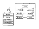
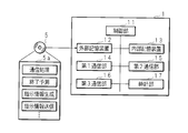
- FIG. 3 is a block diagram showing a configuration example of the production efficiency improving apparatus 1 according to the first embodiment.
- the production efficiency improving apparatus 1 receives information transmitted from the transfer system 3, for example, information for predicting the time when the object to be processed arrives at the processing apparatus 2, and performs the apparatus state soundening process on the processing apparatus 2.
- the computer has a function of instructing the processing device 2 to execute a preparatory process such as changing a processing condition that needs to be changed and can be changed in advance.
- the production efficiency improving device 1 has a function of inquiring the production execution control device 4 about the schedule of the object to be processed for the processing device 2 having a specific processing process or a processing device 2 group composed of the same type of processing device 2. Based on the function of inquiring the processing device 2 about the number of processing objects that can be processed before the next periodic apparatus state restoration process execution or the processable time, the received process schedule, and the periodic apparatus state restoration process schedule The computer has a function of optimizing the insertion timing of the apparatus state sounding process into the processing apparatus 2 and a function of instructing insertion of the apparatus state sounding process into the processing apparatus 2.
- the production efficiency improving device 1 instructs the early insertion of the periodic device state soundening process of the processing device 2 according to the interval and frequency until the workpiece arrives next. If there are a plurality of processing devices 2 that can be instructed to postpone or can perform equivalent processing in the group of processing devices 2, the processing device 2 is executed so that the periodic maintenance work is not concentrated in the same period. To instruct.
- the production efficiency improving device 1 is a computer including a control unit 11 that controls the operation of each component of the production efficiency improving device 1, for example, a CPU (Central Processing Unit).
- the control unit 11 includes an internal storage device 13 such as a ROM or a RAM connected via a bus, a hard disk drive, a solid state drive, a CD-ROM that is a device that can read data from a portable recording medium.
- An external storage device 12 such as a ROM drive, first to third communication units 14, 15, 16 and a clock unit 17 are connected.
- the ROM is a non-volatile memory such as a mask ROM or EEPROM that stores a control program necessary for the operation of the computer.
- the RAM is a volatile memory such as a DRAM or SRAM that temporarily stores various data generated when executing the arithmetic processing of the control unit 11 and a control program necessary for the operation of the computer.
- the first to third communication units 14, 15, and 16 are interfaces for transmitting and receiving information to and from the processing device 2, the conveyance control device 31, and the production execution control device 4, respectively. The transmission / reception of various information by the first to third communication units 14, 15, 16 is controlled by the control unit 11.
- the computer program 5a is a portable medium recorded in a computer-readable manner, such as a recording medium 5 such as a CD (Compact Disc) -ROM, a DVD (Digital Versatile Disc) -ROM, a BD (Blu-ray Disc), or a hard disk drive. Recorded on a solid state drive.
- the control unit 11 reads the computer program 5a from a portable medium or a hard disk drive in which the computer program 5a is recorded, and stores it in the internal storage device 13.
- the optical disk and the optical disk drive are examples of the recording medium 5 and the external storage device 12, and the computer program 5a is recorded on a flexible disk, a magnetic optical disk, an external hard disk, a semiconductor memory, or the like in a computer-readable manner.
- the external storage device 12 may be configured to read.
- the computer program 5a according to the present invention may be downloaded from an external computer (not shown) connected to the communication network.
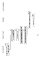
- FIG. 4 and FIG. 5 are flowcharts showing a processing procedure of the production efficiency improving apparatus 1 related to the apparatus state soundening process and the preparation process.
- the conveyance control device 31 that performs conveyance control of the object to be processed based on an instruction from the production execution control device 4 predicts a time at which the conveyance device 32 arrives at the conveyance destination processing device 2.
- Information hereinafter referred to as information relating to arrival prediction
- lot identification information for identifying the object being conveyed by the conveying device 32 are transmitted to the production efficiency improving device 1 (step S11).
- the information related to the arrival prediction is, for example, information including the instruction content of the production execution control device 4 itself. Further, for example, the information related to the arrival prediction is information including the predicted arrival time calculated by the transfer control device 31 based on the instruction content of the production execution control device 4. Note that these pieces of information are merely examples, and are not particularly limited as long as the information can be used for predicting the time when the transport device 32 arrives at the processing device 2, and includes auxiliary information for predicting the arrival time. It is. Examples of the auxiliary information include layout information of the processing device 2 and information indicating past results required for conveyance.
- the control unit 11 of the production efficiency improving device 1 receives the information related to arrival prediction and the lot identification information transmitted from the transfer control device 31 (step S12), and predicts the time when a certain transfer device 32 arrives at the processing device 2. (Step S13). Next, the control unit 11 makes the apparatus state sound by the non-production processing sequence for appropriately maintaining the processing capability or conditions of the processing device 2 before the time when the transport device 32 arrives at the processing device 2 as the transport destination.
- the apparatus state soundening process control information for controlling the operation of the processing apparatus 2 is generated so as to end the process (step S14). And the control part 11 transmits the apparatus state soundening process control information produced
- the apparatus state soundening process control information includes a predicted time when the object to be processed arrives at the processing apparatus 2 as the transport destination, and the apparatus state soundening process in the processing apparatus 2 can be completed before the predicted time. If the sounding process is started and cannot be completed before the predicted time, the device state sounding process is postponed, and if the device state sounding process is in progress, the device state sounding is performed before the transport device 32 arrives. This is information for controlling the operation of the processing device 2 so as to finish the processing.
- control unit 11 of the production efficiency improving device 1 may be configured to operate as follows.
- the control unit 11 receives information indicating that the processing on the object to be processed W in one processing apparatus 2 has been completed by the first communication unit 14 or based on the information received by the first communication unit 14.
- the time at which the processing on the object to be processed W in the processing apparatus 2 ends is predicted, the time at which the transport apparatus 32 is predicted to arrive at the one processing apparatus 2, and the object to be processed in the one processing apparatus 2
- the process control information for instructing the execution of the apparatus state sounding process is generated based on the time when the process is predicted to end, and the generated process control information is transmitted to the one processing apparatus 2 by the first communication unit 14. Send to.
- This processing control information is, for example, when the device state soundening process in the processing device 2 is expected to end around the arrival time of the transport device 32, that is, at a time around a predetermined time from the scheduled arrival time of the transport device 32. Transmitted to the device 2. That is, the control unit 11 determines the time between the time when the conveying device 32 is predicted to arrive at the one processing device 2 and the time when the processing on the workpiece W in the one processing device 2 is predicted to end, that is, When the difference between the time required for the device state soundening process and the calculated time is less than a predetermined value, the process control information for instructing the execution of the device state soundening process is added to the above-mentioned process control information. To the processing device 2. When the processing device 2 receives the processing control information, the processing device 2 executes a device state soundening process such as cleaning.
- a device state soundening process such as cleaning.
- the processing device 2 receives the device state soundness processing control information transmitted from the production efficiency improving device 1 (step S16). Then, the processing device 2 executes processing such as start or postponement of the device state restoration processing according to the received device state restoration processing control information (step S17). In addition, the processing device 2 executes a process such as changing the execution content of the device state soundening process so that the device state soundening process is terminated at the scheduled arrival time of the object as much as possible.
- control unit 11 of the production efficiency improving apparatus 1 transmits the lot identification information received in step S12 to the production execution control apparatus 4, and the processing conditions of the target object corresponding to the lot identification information, that is, the processing apparatus 2 Requests a condition for executing a specific process on the object to be processed (step S18).
- the production execution control device 4 specifies the processing conditions of the target object corresponding to the lot identification information in response to a request from the production efficiency improvement device 1, and sets the processing condition information including the specified processing conditions as the production efficiency improvement device. 1 (step S19).
- the control unit 11 of the production efficiency improving device 1 receives the processing condition information transmitted from the production execution control device 4 (step S20).
- the processing condition information is directly received from the production execution control device 4, but may be configured to be received via another device, for example, a transfer control device.
- the control part 11 produces
- the prepared preparation control information is transmitted to the processing apparatus 2 that is the transport destination of the object to be processed (step S22).
- the processing device 2 that is the transfer destination of the object to be processed receives the preparation process control information transmitted from the production efficiency improving device 1 (step S23). Then, the processing device 2 can process the processing conditions of the target object currently being processed, or if there is no target object currently being processed, the processing conditions for the immediately previous target object, and the processing conditions for the target object to be arrived. And the conditions to be changed are specified (step S24). Note that the processing conditions for the object to be processed are included in the preparation process control information. Next, the processing device 2 executes a preparation process for changing a processing condition that can be changed in advance among the processing conditions to be changed (step S25). For example, the temperature condition is changed.
- the transport control device 31 transports the target object to the designated processing device 2 in accordance with the target object delivery instruction from the production execution control device 4, and places the target object on the load port of the processing device 2.
- the processing device 2 has completed the preparation processing necessary for processing on the arrived processing object, and executes specific processing on the arrived processing object in accordance with an instruction from the production execution control device 4. .
- the apparatus state soundening process competing with the process for the object to be processed is completed or postponed. Since preparatory processing for changing the processing conditions is also performed, processing of the object to be processed can be started quickly.
- the arrival of the object to be processed is reported to the production execution control device 4.
- the production execution control device 4 instructs the processing conditions of the object to be processed that has arrived at the processing device 2
- the time from the arrival of the object to be processed to the start of processing on the object to be processed can be shortened. it can.
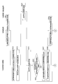
- 6 and 7 are flowcharts showing a processing procedure of the production efficiency improving apparatus 1 related to the periodic apparatus state soundening process.
- the process arrival optimization and the optimization process of the periodic device state soundening process based on the prediction will be described, and other process steps will be described. Is omitted.
- Periodic apparatus state soundening process occurrence schedule information is transmitted to the efficiency improvement apparatus 1 (step S51).
- the periodic apparatus state restoration process occurrence schedule information includes information indicating the time at which the apparatus state restoration process is executed.
- the control unit 11 of the production efficiency improving apparatus 1 receives the periodic apparatus state soundening process occurrence schedule information transmitted from the processing apparatus 2 (step S52). And the control part 11 requests
- production schedule information to the production execution control apparatus 4 (step S53). .
- the production execution control device 4 transmits processing schedule information indicating the processing schedule of the object to be processed in the processing device 2 to the production efficiency improving device 1 in response to a request from the production efficiency improving device 1 (step S54).
- the control unit 11 of the production efficiency improving device 1 receives the processing schedule information transmitted from the production execution control device 4 (step S55). And the control part 11 performs the period when the process with respect to a to-be-processed object is performed in the said processing apparatus 2 based on periodic apparatus state soundening process generation
- the processing device 2 receives the periodic device state restoration processing control information (step S59), and executes the periodic device state restoration processing as scheduled (step S60).
- control part 11 is the number of the to-be-processed objects which can be processed before performing the next periodic apparatus state soundening process, or processable time Is requested (step S61).
- the processing device 2 calculates processing amount information in response to a request from the production efficiency improving device 1, and transmits the calculated processing amount information to the production efficiency improving device 1 (step S62).
- the processing device 2 stores, for example, the average number of objects to be processed that can be processed per unit time, and is based on the time from the current time to the time when the next periodic device state soundening process is executed, and the average number Thus, the number of processable objects is calculated.
- the control unit 11 of the production efficiency improving device 1 receives the processing amount information transmitted from the processing device 2 (step S63), and based on the received processing amount information, the processing object that can be assigned to the processing device 2 is received.
- the order of the quantity and the periodic apparatus state soundening process is optimized (step S64). Optimization is, for example, a state in which the period during which processing is performed on the object to be processed in each processing apparatus 2 and the period during which periodic apparatus state soundening processing is performed in each processing apparatus 2 do not overlap. is there.
- the end point of the periodic device state soundening process and the start point of the process for the object to be processed are preferably set longer than a predetermined time. This is because it may take time for the preparation process corresponding to the target object to be processed next after the periodic apparatus state restoration process.
- the control unit 11 of the production efficiency improving device 1 generates periodic device state soundening process control information for causing the processing device 2 to execute the optimized periodic device state soundening process (step S65), and generates Periodic apparatus state soundening process control information is transmitted to the processing apparatus 2 (step S66).
- the production efficiency improving device 1 instructs or postpones the insertion of the periodic maintenance work of the processing device 2 at an early stage according to the interval and frequency until the next processing object arrives. If there are a plurality of processing devices 2 capable of executing the equivalent processing, the processing device 2 is instructed to execute the periodic device state soundening processing so as not to concentrate.
- the processing device 2 receives the periodic device state restoration processing control information (step S67), and changes the timing for starting the periodic device state restoration processing according to the received periodic device state restoration processing control information (Ste S68).
- the waiting time from when the object to be processed arrives at the processing apparatus 2 to when the process for the object to be started is shortened, , Avoiding a situation in which the processing apparatus 2 cannot process the target object during the apparatus state soundening process even though the target object to be processed has arrived at the processing apparatus 2, The processing performance of the entire processing apparatus 2 can be improved.
- the efficiency of the device state restoration process and the preparation process is performed without considering the past results, but the device state restoration process control information and the preparation process transmitted to the processing device 2 are performed.
- the processing performance for the object to be processed when the processing apparatus 2 is operated for example, the number of particles increased on the object before or after the process or the film deposition rate
- the calculated processing performance is associated with the device state soundening process control information, the preparation process control information, and the process control information periodically and stored in the external storage device 12, and thereafter stored in the external storage device 12. It is preferable to optimize the operation of the processing apparatus 2 in consideration of information.
- the processing for the object to be processed can be made more efficient.
- the production efficiency improving device 1 may be constructed so as not to have a direct connection port with the production execution control device 4.
- the processing object lot information received by the production efficiency improving apparatus 1 from the transfer control system 6 is transmitted to the processing apparatus 2 as it is, and the processing apparatus 2 is connected to the production execution control system via a conventional connection port (not shown). You can make an inquiry.
- the production efficiency improving apparatus 1 inquires of the production execution control apparatus 4 about the flexibility of instructions from the production execution control apparatus 4.
- the production efficiency improving device 1 is used to specify an alternative processing device 2 and an alternative processing condition when any of the processing devices 2 may be selected between the same types of processing devices 2 to process the workpiece W. Request information.
- indicates execution of the periodic apparatus state soundening process by the processing apparatus 2, the process apparatus 2 which can be replaced performs a periodic apparatus state soundening process at a different timing Thus, the operation of the processing device 2 is controlled.
- the production efficiency improving device 1 controls the operation of the processing device 2 so that the processing device 2 that can execute the same type of processing does not perform the periodic device state soundening processing in parallel.
- the modification 1 the insertion of the periodic apparatus state soundening process in the processing apparatus 2 can be leveled, and the processing performance of the plurality of processing apparatuses 2 as a whole can be improved.
- the production efficiency improving apparatus 1 inquires of the production execution control apparatus 4 about the flexibility of instructions from the production execution control apparatus 4.
- the production efficiency improving apparatus 1 identifies the object to be processed W of each lot when the processing execution order of the plurality of sets of objects to be processed W processed by one processing apparatus 2 may be reversed. Lot identification information and the processing conditions of the workpiece W of each lot are requested.
- the control part 11 of the production efficiency improvement apparatus 1 transmits the process condition of the to-be-processed object W of each lot to the processing apparatus 2, and the change of the process condition of the process with respect to the to-be-processed object W performed in order becomes the minimum. Let the order be determined.
- the production efficiency improving apparatus 1 transmits control information for controlling the operation of the transfer apparatus 32 to the transfer control apparatus 31 so that the workpieces W of each lot are transferred to the process apparatus 2 in the determined order. To do. Moreover, the control part 11 of the production efficiency improvement apparatus 1 controls operation
- the production efficiency improving apparatus includes a delivery result of the object to be processed W by the transfer device to a processing device group that performs processing prior to processing performed by one processing device group a (a plurality of processing devices capable of performing the same processing), and the preceding Using the average time from the delivery of the processed material to the processing device to be processed until the collection, the number of objects W to be processed for the processing device group product a is predicted, and the processing device group a Predict changes in processing load.
- priority is given to the time required for maintenance requiring the transition to the state mode in which the apparatus is not operated in the processing apparatus a, and the time and time are used to calibrate and wear the robot and measuring instrument.
- the state of the processing apparatus can be maintained in a state suitable for the processing target object W without impairing the productivity of the line.
- the production efficiency improving apparatus performs the delivery results of the workpiece W to the processing device group that performs processing prior to processing performed by one processing device group a (a plurality of processing devices capable of performing the same processing), and the preceding processing is executed.
- the number of workpieces W to which a processing request for the processing device group product a is issued is estimated using the average time from delivery of the processed material to the processing device to be collected, and the processing load of the processing device group a. Predict changes. When the processing load is high, the processing apparatus is instructed to suppress the non-production process having a long return time to the processable state.
- the processing apparatus that has received a long non-production processing suppression instruction from the production efficiency improving apparatus does not perform conditioning (plasma cleaning or the like) with a long return time to the processable state, and arrives at the object W to be processed next in the idle state. Let me wait.
- the MES designates a device group without specifying a device to process the processing object.
- the production efficiency improvement device has a function of selecting a device / chamber from a large number of processing devices of the same type.
- the processing load of the processing device group a is low, some of the devices can be put into an energy saving operation mode to reduce power and other utilities.
- the device having the best condition is selected to perform processing without interruption, and one chamber for always placing an express train is taken. be able to.
- the production efficiency improvement apparatus 1 has two types of conditions for instructing execution of the apparatus state soundening process such as cleaning.
- a gas called dry cleaning is used to remove deposits in the chamber, an atmosphere maintenance called purging, a process for reducing particles, and moisture in the chamber called baking are removed. Processing to be performed.
- the first condition is that when the vacant time until the scheduled time at which the workpiece W arrives is vacant for a predetermined set time or more, the processing device 2 executes a device state soundening process such as cleaning.
- the condition is that, when the condition is reached, the apparatus state soundening process such as cleaning is executed even if the vacant time until the scheduled arrival time of the next object to be processed W is not longer than a predetermined set time. It is.
- Each condition is set, for example, as the number of times the process for the object W has been performed after the most recent apparatus state restoration process.
- the first cumulative set value that defines the first condition is 40 times
- the second cumulative set value that determines the second condition is 50 times.
- the number of times of processing on the workpiece W in a certain processing apparatus 2 is 40 times or more and the vacant time until the scheduled arrival time of the workpiece W to be processed next is a predetermined set time or more
- production The efficiency improving device 1 instructs the processing device 2 to execute the device state soundening process. Even after the processing of the workpiece W has been performed 40 times or more, if the idle time until the scheduled arrival time of the workpiece W to be processed next continues to be less than the set time, the first condition is satisfied.
- the execution instruction of the apparatus state soundening process based on is not performed. Even under such circumstances, if the processing of the workpiece W reaches the second cumulative set value 50 times and satisfies the second condition, the production efficiency improving apparatus 1 will process the workpiece W to be processed next.
- the processing apparatus 2 is instructed to execute the apparatus state sounding process regardless of the idle time until the scheduled arrival time.
- the predetermined time here is a transfer timing at which the apparatus state soundening process according to the second condition is performed by setting the time equal to or longer than the time required for the apparatus state soundening process.
- the apparatus state soundening process can be performed without affecting the time during which the process on the workpiece W can be performed.
- the predetermined set time here to a time shorter than the time required for the device state soundening process, for example, half the time required for the device state soundening process.
- the influence on the time during which the process can be performed on the workpiece W can be reduced. For example, consider a case where the time required for the device state soundening process is set to 30 minutes and the predetermined set time is set to 15 minutes. After the most recent apparatus state restoration process, if the number of times that the process on the object to be processed W has reached 40 times and the time for the next object to be processed W is scheduled to arrive is 15 minutes or more, the production efficiency improving apparatus 1 causess the device state soundening process to be performed.
- the device state is sound using this 16 minutes free time. Therefore, the influence on the processing time of the object W is only 14 minutes instead of 30 minutes of the device state soundening processing. For example, the second condition is satisfied regardless of the free time. When compared with the case where maintenance is performed, it is possible to improve the processing capacity of the entire production process statistically.
- the cumulative value of the number of times of processing is illustrated as a value to be compared with the specific first and second cumulative set values in the first and second conditions, that is, a numerical value indicating the state of the processing device 2, It is good also as a cumulative value of the film thickness which adheres to a chamber inner wall for every time, or the number of particles.
- the production efficiency improving device 1 may obtain and calculate information such as the cumulative number of processing after the most recent device state restoration processing from the processing device 2, or until the next device state restoration processing is performed.
- the remaining number of processes may be obtained from the processing device 2.
- the cumulative value of the film pressure may be obtained by automatic measurement, or may be calculated by a calculation formula based on the processing conditions and processing time. You may calculate based on the measurement result which shows the number of particles in the process chamber obtained by an external measuring device, or the measurement result of a film thickness.
- the set time which is one of the set values of the first condition, may be set by a method that is easy for the user to recognize.
- the set time is set as a free time during which the process on the workpiece W is not performed.
- it may be set not as a free time but as a time during which the apparatus state soundening process may be continuously executed until after the object to be processed W arrives next.
- it can be said that it is easier for the user to set conditions if the latter method is used. That is, when the setting time of the first condition is set to 15 minutes, the number of processes is equal to or greater than the first cumulative number of processes, and 15 minutes of the scheduled time for the next object to be processed W to arrive. If the device state restoration process is completed by a later time, the execution of the device state restoration process is instructed.
- the time required for the device state soundening process may be set in the production efficiency improvement device 1, and the production efficiency improvement device 1 has information for specifying the recipe of the adjustment processing, and based on that information. It is possible to inquire the processing device 2 about the required time, or to keep the time obtained by inquiring the processing device 2 in the past, or to improve the production efficiency based on the time required for the adjustment processing in the past 1 may be a statistically calculated time.
- the processing procedure for realizing the above processing contents is as follows.
- the control unit 11 of the production efficiency improving device 1 receives the information related to the arrival prediction transmitted from the conveyance control device 31 at the second communication unit 15. And the control part 11 estimates the time when a certain conveying apparatus 32 arrives at the one processing apparatus 2 based on the information received in the 2nd communication part 15. FIG. On the other hand, based on the information received by the first communication unit 14, the control unit 11 predicts the time at which the process on the workpiece W in the one processing device 2 ends.
- the control unit 11 of the production efficiency improvement apparatus 1 when it is configured to transmit to the production efficiency improvement apparatus 1 information indicating that the processing on the workpiece W in each processing apparatus 2 is completed, the control unit 11 of the production efficiency improvement apparatus 1 By receiving the information, the one processing device 2 predicts the time at which the processing on the workpiece W is finished. In addition, the control unit 11 determines the one processing device 2 based on information transmitted from the processing device 2, for example, information that does not directly indicate an end time, such as the number of unprocessed objects W to be processed. It may be configured to predict the time at which the process on the object W is completed.
- control unit 11 performs the device state soundening process based on the time when the transfer device 32 arrives at the one processing device 2 and the time when the processing on the workpiece W is completed in the one processing device 2. Is transmitted to the first processing device 2 by the first communication unit 14. Specifically, the control unit 11 has a cumulative value of processing on the workpiece W related to production in one processing device 2 equal to or greater than a specific first cumulative set value, and processing is performed by the single processing device 2. If the time until the workpiece W arrives at the processing device 2 after the end is equal to or longer than a specific set time, processing control information for instructing the processing device 2 to execute the device state soundening processing is transmitted. To do.
- the first cumulative set value and the set time are set in advance or stored in the external storage device 12 as values input from the outside.
- the processing device 2 the accumulated value of the processing to the workpiece W related to production is transmitted from the processing device 2 to the production efficiency improving device 1, and the production efficiency improving device 1 receives the accumulated value. Is getting by.
- the control unit 11 is scheduled to arrive when the cumulative value of the process on the workpiece W related to production in the one processing apparatus 2 is equal to or larger than the second cumulative set value larger than the first cumulative set value. Processing control information for instructing execution of the apparatus state soundening process is transmitted to the processing apparatus 2 regardless of the time.
- the processing device 2 acquires the time when the transport device 32 arrives at the processing device 2, or acquires information for predicting the time from the transport device 32 and predicts the time.
- the processing apparatus 2 has memorize
- the processing device 2 Execute the conversion process.
- the production efficiency improving apparatus 1 according to the modified example 7 has the same configuration as that of the modified example 6, and further, the number of processing chambers that do not perform the device state soundening process such as cleaning between the processing chambers that can perform the same processing (production is possible).
- the number of processing chambers in other words, the number of processing chambers capable of processing the workpiece W is set.
- the number of processing chambers is stored in the external storage device 12 of the production efficiency improving device 1.
- the external storage device 12 also stores information for specifying a processing chamber that can perform the same processing.
- the information is, for example, information obtained by associating processing chamber identification information for identifying a plurality of processing chambers with information indicating processing contents that can be performed in the processing chamber.
- processing chambers in one processing apparatus 2 there are five processing chambers in one processing apparatus 2 that can perform the same processing on the workpiece W, and processing chambers that do not perform processing such as cleaning between the processing chambers that can perform the same processing simultaneously. Assume that 3 is set as the number.
- the control unit 11 of the production efficiency improving device 1 satisfies the first condition in all the processing chambers, and even if there is a vacant time until the workpiece W arrives for a set time or more, the two processing chambers Is instructed to execute the apparatus state soundening process, and the remaining three processing chambers are not instructed to execute the apparatus state soundening process.
- this is not limited to one processing apparatus 2, and it is more preferable to manage the processing chambers that can perform the same processing across a plurality of processing apparatuses 2 in a unit of a certain bay in a factory.
- the empty processing chamber is less than the predetermined set value. Even if it becomes, the device state soundening process is executed. That is, even if there are four processing chambers that can perform the same processing, if all of them reach the first condition, that is, if the cumulative number of processing times for the workpiece W reaches 50 times, An instruction to execute the device state soundening process is issued to all the two processing chambers. This is to prevent adverse effects on the processing performance on the workpiece W.
- the production efficiency improving apparatus 1 according to the modified example 8 has the same configuration as that of the modified example 6 or 7, and is configured to perform a preparation process before the workpiece W arrives at the processing chamber.
- the processing sequence is called a recipe.
- the processing start temperature is 400 ° C.
- the processing apparatus 2 is made to perform a process to be prepared, that is, a preparation process before the workpiece W arrives at such a processing apparatus 2.
- the control unit 11 of the production efficiency improving device 1 processes the type of recipe of the workpiece W to be processed next, for example, the recipe ID or the name of the recipe.
- the apparatus 2 may be taught, or a preparation recipe and execution thereof may be instructed to the processing apparatus 2.
- the processing apparatus 2 takes out a preparation recipe associated with the recipe, and the processing apparatus 2 executes the preparation recipe.
- the preparation process can be completed in the free time until the workpiece W arrives, and the time from the arrival of the workpiece W to the start of processing on the workpiece W can be reduced. It can be shortened.
- the control unit 11 of the production efficiency improving apparatus 1 sets the processing chamber to 300 ° C. before the object to be processed W arrives at the processing apparatus 2.
- Processing control information for instructing to transmit is transmitted to the processing device 2.
- the control unit 11 may instruct the processing apparatus 2 to set the processing chamber to 300 ° C., or the production efficiency apparatus 1 notifies the processing apparatus 2 of the recipe ID or name.
- the processing apparatus 2 may select and execute the preparation process based on the recipe ID or name.
- control unit 11 instructs to insert a plasma cleaning of the processing chamber or an aging process with a new gas type before the workpiece W arrives.
- the control unit 11 of the production efficiency improving apparatus 1 transmits this ID to the production execution production apparatus and produces the contents (recipe) to be processed by the processing apparatus 2. Asked from the execution control device 4.
- the ID of the object to be processed W or the ID of the FOUP is, for example, the ID of the object to be processed W (or the FOUP containing the object to be processed W) conveyed by the conveying device 32 of the conveying device 32, the stocker or the conveying device 32. It is obtained by reading with a reader provided in the transport path.
- the production execution control device 4 notifies the ID of the object to be processed W to be conveyed to the conveyance control device 31, and the conveyance control device 31 is configured to transmit to the production efficiency improving device 1 so that the processing object is processed. You may comprise the production efficiency improvement apparatus 1 so that ID of the body W may be acquired.
- the processing apparatus 2 may notify the production efficiency improving apparatus 1 of the ID.
- the FOUP that accommodates the workpiece W has a barcode or a tag that can rewrite data without contact.
- the ID can be obtained by reading this bar code or tag.
- the production efficiency improving apparatus 1 according to the modified example 9 has the same configuration as that of the modified example 8, and further, the target processing apparatus 2 is selected from the group of processing apparatuses 2 so that the preparation process is unnecessary. It is configured to select. For example, when the first processing apparatus 2 is on standby at 300 ° C., the second processing apparatus 2 is on standby at 250 ° C., and when processing an object to be processed W that needs to be prepared at 250 ° C.
- the control unit 11 of the production efficiency improving apparatus 1 selects not to select the first processing apparatus 2 but to perform processing by the second processing apparatus 2.
- the processing apparatus 2 when the processing apparatus 2 is executing a recipe for the processing condition A and the workpiece W of the processing condition B and the workpiece W of the processing condition A are waiting for processing, the processing condition B in the original order
- the processing object W is processed first, but in order to eliminate the need for advance preparation, the processing order is changed so that the processing of the processing object W under the processing condition A is performed first.
- the production efficiency improving apparatus 1 is configured so that the preparation process is started when the remaining free time becomes the time required for the advance preparation. For example, if the time required from the start of the preparation process to the end is 10 minutes and there is 30 minutes before the next object to be processed W arrives, the preparation process is immediately started. Instead, the execution of the preparation process is instructed when the free time approaches the time required for the preparation process.
- the control unit 11 uses the third communication unit 16 or the first communication unit 14 to indicate information indicating the time required for the preparation process and the energy per unit time when the processing in the processing device 2 is completed.
- the consumption amount, the energy consumption amount per unit time when the state where the preparation process is completed, and the information indicating that the processing on the object to be processed in the processing apparatus 2 is completed are received.
- the energy consumption is, for example, power or gas consumption.
- the control part 11 is the state which the preparation process was complete
- control part 11 is the energy consumption per unit time when the state in which the preparation process was complete
- finished is more energy per unit time when the state in which the process in the said processing apparatus 2 was complete
- finished Processing control information for instructing execution of the preparation process at a time before and after the time required for the preparation process from the arrival time when the transport apparatus 2 is predicted to arrive at the processing apparatus 2 when the consumption amount is greater than the consumption amount. Is transmitted to the processing device 2 by the first communication unit 14.
- the production efficiency improving apparatus 1 according to the modified example 10 is configured to replace the dummy wafer necessary for a predetermined apparatus state soundening process without reducing the processing efficiency in the processing apparatus 2 as much as possible.
- a dummy wafer that is not a production wafer is placed on the susceptor in order to reduce damage to the susceptor on which the workpiece W in the processing chamber is placed.
- the vertical batch processing apparatus 2 can process a plurality of objects to be processed W at a time, a dummy wafer, which is a wafer that is not a production wafer, is placed near the end of a boat on which the plurality of objects to be processed W are placed. This improves the quality and uniformity of the film produced by processing on the production wafer.
- Such a dummy wafer becomes a cause of adverse effects such as particles when the number of times of use increases. Therefore, it is necessary to replace the dummy wafer when the number of times of use reaches a predetermined number.
- the production efficiency improving apparatus 1 has a first condition for exchanging dummy wafers as a condition for exchanging dummy wafers, and a second condition that dummy wafer exchange is indispensable if there is enough time. And have.
- the first condition is set as 40 times as the cumulative set use number and 5 minutes as the free time as the set value
- the second condition is set as the second cumulative set use number that requires replacement. 50 times may be set as a set value.
- the production efficiency improving apparatus 1 has a predetermined set time, for example, 5 minutes or more, until the number of times the dummy wafer is used reaches 40 times and the next processing target W is scheduled to arrive. If there is, the replacement of the dummy wafer is instructed.
- the replacement instruction of the dummy wafer is given to a person who operates the processing apparatus 2 called an operator through an operator interface of the processing apparatus, for example, a message displayed on the screen, a light alarm display by a signal tower, or a combination thereof. Is called.
- a transfer control device that instructs the processing apparatus 2 to issue a dummy wafer, and causes the transfer device 32 to take out and carry the FOUP that accommodates the discharged wafer and is placed in the load port.
- An example of requesting to do is given.
- the dummy wafer discharged from the apparatus is stored in the FOUP placed on the load port, the FOUP is removed from the processing apparatus 2, and the FOUP containing the dummy wafer to be newly inserted into the processing apparatus 2 is stored. Is placed on the load port and a dummy wafer is taken out from the FOUP.
- this replacement processing is performed when a free time until the workpiece W arrives exceeds a predetermined time. Therefore, it is possible to reduce a decrease in production capacity that obstructs the placement of the FOUP containing the workpiece W to be processed.
- the number of times the dummy wafer is used is the number of times set as condition 2 in order to reduce the occurrence of adverse effects such as particles.
- the replacement of the dummy wafer is instructed regardless of the free time until the next processing object W to be processed arrives.
- the production efficiency improvement device 1 bundles the processing devices 2 that can perform the same processing.
- the production execution control device 4 does not select one processing device 2 to be processed, but selects it in units of groups that can perform the same processing, and in which group the information specifying the processing target W and the processing target W are selected.
- the production efficiency improving apparatus 1 is instructed whether to process.
- the production efficiency improving apparatus 1 receives the production instruction information for each group, the production efficiency improving apparatus 1 determines which processing apparatus 2 in the group is to perform the process.
- the production efficiency improving device 1 stores information indicating a group to which a plurality of processing devices 2 belong in the external storage device 12.
- the following method can be given as a specific example of a method for determining which processing device 2 in the group the production efficiency improving device 1 performs processing.
- the production efficiency improving apparatus 1 determines a processing apparatus 2 that does not require advance preparation from the group, and causes the processing apparatus 2 to process the workpiece W.
- the production efficiency improving apparatus 1 cannot perform a desired process unless the state of the processing apparatus 2 is good, that is, when performing a process that is easily affected by the state of the processing apparatus 2, the production efficiency improving apparatus 1 A device having a good state is determined, and the determined processing device 2 processes the workpiece W.
- An apparatus having a good state is, for example, the processing apparatus 2 having a small number of measured particles in the processing chamber.
- the device in which the state is not good is the processing device 2 that will soon reach the period in which maintenance should be performed in a state in which the device is not operated, such as cleaning of the state of the device or cleaning by opening the part replacement chamber.
- the processing device 2 that will soon reach the period in which maintenance should be performed in a state in which the device is not operated, such as cleaning of the state of the device or cleaning by opening the part replacement chamber.
- the measurement is performed with these measuring devices after the processing. Based on this measurement result, it is determined whether it should be cleaned soon or it is dirty. For example, for a processing lot that needs to have fewer particles than other processing lots, a production efficiency improvement device is arranged so that the object to be processed W is thrown into the processing device 2 with fewer particles based on these measurement results. 1 gives instructions.
- These measuring instruments may be provided in the processing apparatus 2 or may be placed somewhere on the factory line and the workpiece W may be carried there for measurement.
- the control unit 11 of the production efficiency improving device 1 sends the processing control unit 31 to the determined processing device 2 or the processing target W so that the processing target W is processed by the processing device 2 thus determined.
- An instruction is given to transport the transport container containing the processing body W.
- the production efficiency improving device 1 may be configured to transmit the processing content instructed from the production execution control device 4, for example, an ID for specifying a processing recipe, to the determined processing device 2. Further, the processing device 2 that has received the workpiece W may be configured to inquire the processing content to the production execution control device 4.
- An object to be processed W that cannot perform a desired process unless the processing apparatus 2 is in a good state is identified by the following method.
- the production efficiency improving device 1 receives the designation of the processing chamber that should not be processed from the production execution control device 4 corresponding to the object to be processed W or corresponding to the processing recipe, and the designated processing chamber It is preferable that the processing target device 2 is not processed.
- the specifications required for the processing are advanced.
- the processing chamber does not satisfy this specification, it has information on which of the processing chambers it can be processed in, and the processing chamber is selected so that preparation processing is not required In addition, select from the processing chambers that may perform the processing.
- the information on which processing chamber may be processed may be information obtained by the production efficiency improving apparatus 1 as an answer to the production execution control apparatus 4 based on the ID of the workpiece W.
- a lot ID which is a recipe ID, is obtained from the production execution control device 4 based on the ID of the workpiece W, and the lot ID or the lot ID naming rule may be associated. For example, if the lot ID starts with A, the processing can be performed in the processing chambers a, b, c, and d in the processing chamber group.
- the processing instruction apparatus has a correspondence table of processing chambers that may perform processing corresponding to the naming convention.
- the production processing system includes a plurality of processing devices 2, a transport system 3 having a plurality of transport devices 32 and a transport control device 31 that controls the operation of the transport device 32, and the processing device 2. And a production execution control device (processing execution control device) 4 that gives control instructions to the transfer system 3 and controls the operation of each device, and various types of operations among the plurality of processing devices 2, the transfer system 3, and the production execution control device 4. And a production efficiency improving device 1 for communicating information.
- the configuration of the production execution control device 4 is the same as that of the first embodiment.
- the processing apparatus 2 is a substrate processing apparatus such as a plasma CVD apparatus, a plasma etching apparatus, a sputtering apparatus, or a PVD apparatus that processes an object to be processed such as a glass substrate for manufacturing an organic EL device or a silicon wafer for manufacturing a semiconductor device. 2. Further, the processing apparatus 2 has a function of transmitting information for predicting the end time of the process to the production efficiency improving apparatus 1 before the process on the object to be processed is completed. Further, the processing device 2 has a function of transmitting processing end information indicating that the processing on the object to be processed has ended to the production execution control device 4.
- a substrate processing apparatus such as a plasma CVD apparatus, a plasma etching apparatus, a sputtering apparatus, or a PVD apparatus that processes an object to be processed such as a glass substrate for manufacturing an organic EL device or a silicon wafer for manufacturing a semiconductor device. 2. Further, the processing apparatus 2 has a function of transmitting information for predicting the end time of the process to the production efficiency
- the processing apparatus 2 has an adjustment processing function for changing a processing condition parameter that can be changed in advance prior to the arrival of an object requiring processing conditions (recipe) to be changed.
- the processing device 2 has a function of preparing an environment for processing an object to be processed by executing a cleaning process, an aging process, or the like when the conditions are largely different before and after the change of the processing conditions.
- the processing apparatus 2 is an apparatus state comprising a non-production processing sequence such as automatically cleaning the interior of the processing chamber, aging, purging gas, etc. in order to keep the processing capability and conditions appropriate. It has a device state restoration processing function for automatically executing the restoration processing.
- the processing device 2 has a function of transmitting warning information when the total number of processed objects or the total processing time exceeds a certain value and prompting an operator to perform parts replacement or cleaning. Furthermore, the processing apparatus 2 has a function of transmitting processing end information indicating that the processing on the object to be processed has ended to the production efficiency improving apparatus 1.
- One configuration example of the processing apparatus 2 is the same as that of the first embodiment.
- One configuration example of the transport system 3 is the same as that of the first embodiment.
- FIG. 8 is a block diagram showing a configuration example of the production efficiency improving apparatus 1 according to the second embodiment.
- the production efficiency or the hardware configuration of the apparatus 1 is the same as that of the first embodiment.
- FIG. 9 is a block diagram showing an example of a program configuration of the production efficiency improving device framework.
- the program for configuring the production efficiency improvement device 1 has a production efficiency improvement device framework.
- the production efficiency improvement device framework has a modeler unit for generating a model to be controlled and a production efficiency application unit, and the production efficiency application unit communicates with the model of the control target generated by the modeler unit.
- the processing device 2 and the conveyance control device 31 are instructed to perform processing for improving production efficiency by exchanging information.
- the modeler unit includes a transport system modeler unit 1b, a host system modeler unit 1e, and an apparatus system modeler unit 1g, which will be described later, and models and holds state data independently of each other.
- the state data is a mapping of the state of the controlled object. Specifically, the state data includes a carrier state model, a load port state model, a transport job state model, a host processing condition information model, and the like.
- the framework of the program constituting the production efficiency improving apparatus 1 is the processing progress status of the object to be processed W in the processing apparatus 2 and the processing apparatus 2 with the plurality of processing apparatuses 2 that process the object to be processed W.
- An apparatus system adapter unit 1h that functions as a first communication unit that communicates processing control information for controlling the operation of the apparatus, and a conveyance that controls the operation of the conveying apparatus that conveys the workpiece W to the plurality of processing apparatuses 2.
- a transport system adapter unit 1a that functions as a second communication unit that communicates information with the control device; a host system adapter unit 1d that functions as a third communication unit that communicates information with the production execution control device; Based on the information communicated by the device system adapter unit 1h functioning as the first communication means, the processing device 2 that is the communication destination of the information predicts the transport time required to transport the workpiece W.
- a transport system production efficiency application unit 1c that functions as a first processing instruction unit that transmits information to the transport control device 31 by the transport system adapter unit 1a that functions as the second communication unit, and a transport that functions as the second communication unit
- a transport system modeler unit 1b that functions as an arrival time predicting unit that predicts a time point at which the transport device arrives at the one processing device 2 based on information received by the system adapter unit 1a;
- Information indicating that the processing of the object to be processed W in the one processing apparatus 2 has been completed is received by the functioning system adapter unit 1h.
- the device Device system production efficiency application unit that functions as a processing instruction unit that transmits processing control information for instructing execution of the state restoration processing to the one processing device 2 by the device system adapter unit 1a that functions as the first communication unit 1f and the information received by the host adapter unit 1d functioning as the third communication means.
- the production efficiency improving apparatus 1 is configured to absorb the difference in communication specifications with the control target through the transport system adapter section 1a, the host system adapter section 1d, and the apparatus system adapter section 1.
- the program of the production efficiency improvement apparatus 1 has an optimizer that interprets and optimizes events from the control target for each control target, and when a plurality of optimizers perform control in cooperation with each other, It has logic to prohibit inference for objects other than control objects. More specifically, when multiple optimizers perform control in cooperation, an optimizer is responsible for optimizing the control target for which it is responsible based on the inference result of the control target for which the optimizer other than itself is responsible. Means to do. Specifically, the optimizer stores the inference result of the control object that it is responsible for in the internal storage device or the external storage device, and another optimizer performs control in cooperation by referring to this inference result. Means.
- the production efficiency improvement apparatus 1 is good to comprise so that it may branch from the communication path which connects between the production execution control apparatus 4 and the processing apparatus 2, and between the production execution control apparatus 4 and the conveyance control apparatus 31. .
- the production efficiency improving device 1 fails, it can be disconnected without hindering communication on the original communication path.
- the computer program constituting the production efficiency improving device 1 is independent of communication between the production execution control device 4 and the processing device 2 and communication between the production execution control device 4 and the transfer control device 31.
- communication related to production efficiency is configured to be performed. For this reason, when the computer program of the production efficiency improving apparatus 1 is faulty, it can be disconnected without hindering communication on the original communication path.
- the computer program of the production efficiency improvement apparatus 1 can start or stop the function related to the production efficiency improvement without affecting the execution of the production control instruction from the production execution control apparatus 4 for the application on the production efficiency improvement apparatus framework. Then, the production efficiency in both the state where the function related to the production efficiency is activated and the state where the function is stopped are measured and compared.
- a second computer program having a function equivalent to a part or all of the computer program of the production efficiency improvement device 1 is provided for securing backup in the event of a failure in the production efficiency improvement device 1 and for reducing the load. It can be configured to run on other hardware.
- the computer program of the production efficiency improving apparatus 1 has a dynamic replacement mechanism that allows replacement or addition of applications constituting the computer program without stopping the production processing system. Specifically, it is preferable to construct a system that allows a production efficiency improvement device framework and an application to have a dynamic replacement function, and allows a specific application to be exchanged at an arbitrary timing.
- FIG. 10 is a flowchart showing a processing procedure of the production efficiency improving apparatus.
- ⁇ Basic flow for improving production efficiency for transport optimization> The processing apparatus 2 that is executing the process on the workpiece W transmits information necessary for predicting the time when the process on the workpiece W is completed to the production efficiency improving apparatus 1 (step S111).
- FIG. 11 is a flowchart showing an example of an information transmission procedure in the processing device 2.
- the processing device 2 starts processing on the workpiece W (step S131). And the processing apparatus 2 determines whether the process with respect to the to-be-processed object W exists in the set specific process process (step S132). When it determines with it being in a specific process process (step S132: YES), the processing apparatus 2 transmits the information which shows that the process with respect to the to-be-processed object W exists in a specific process process to the production efficiency improvement apparatus 1 (step). S133). This information is information for reporting that the processing sequence in the processing device 2 has passed a specific processing step.
- step S133 When the process of step S133 is completed, or when it is determined that the process is not in a specific process (step S132: NO), the processing device 2 determines whether or not the process for the object to be processed W has been completed (step S134). ). If it is determined that the process has not been completed (step S134: NO), the processing device 2 returns the process to step S132 and continues the process on the workpiece W. If it is determined that the process has been completed (step S134: YES), the processing device 2 transmits the end information to the production execution control device 4 (step S135), and the process ends.
- the set specific processing step is the number of unprocessed workpieces W accommodated in each FOUP for each FOUP arranged in the first and second load ports 21a and 21b.
- the process apparatus 2 is set as a process that has become less than the predetermined number, and the processing apparatus 2 has less than a predetermined number of unprocessed objects W accommodated in the FOUP for each FOUP placed on the load ports 21a and 21b. Report to the production efficiency improvement device 1 at the same timing.
- the set specific processing step is, for example, three steps of the end step of the processing sequence being executed when the processing apparatus 2 is a batch type heat treatment apparatus that processes a plurality of workpieces W simultaneously. This is a processing step set as a predetermined processing step such as the front side.
- the control unit 11 of the production efficiency improving device 1 receives the information transmitted from the processing device 2 by the device system adapter unit 1h (step S112), and based on the received information, the device system modeler unit 1g
- the processing end time at which the processing device 2 that is the information transmission source finishes the processing is predicted (step S113).
- the processing end time is, for example, that the processing in the processing apparatus 2 is completed, and the workpiece W after the processing is collected in the FOUP placed on the load port, so that the FOUP can be carried out. Scheduled time.
- the control unit 11 uses the device system production efficiency application unit 1f to process the information transmission source at a timing according to the process end time. 2 is generated (step S114), and the generated speculative instruction information is transmitted to the transport control device 31 by the transport system adapter unit 1a (step S115).
- the speculative instruction information is an example of control information related to the control of the transport device 32.
- the conveyance control device 31 receives the speculative instruction information transmitted from the production efficiency improving device 1 (step S116). Then, based on the received speculative instruction information, the transport control device 31 executes the vehicle allocation scheduling of the transport device 32 and the standby process of the transport device 32 (step S117), and transmits a movement instruction to the transport device 32 ( Step S118).
- the instruction to be performed in step S118 is an instruction relating to speculative preparation that is performed prior to the definitive control instruction transmitted from the production execution control device 4.
- the collection instruction may be transmitted at the same time as the movement instruction is transmitted to the conveying device 32 (step S118).
- the transport device 32 receives an instruction from the transport control device 31 (step S119). Then, the transfer device 32 moves to the vicinity of the instructed processing device 2 in accordance with the received instruction (step S120). That is, the transport device 32 for collecting the workpiece W processed by the processing device 2 has moved to the processing device 2 prior to an instruction from the production execution control device 4. Next, the transfer device 32 carrying the workpiece W to be processed next moves to the vicinity of the instructed processing device 2 (step S121).
- FIG.12 and FIG.13 is the flowchart which showed the process sequence of the production efficiency improvement apparatus 1 which concerns on an apparatus state soundening process and a preparation process.
- the transport control device 31 that performs transport control of the workpiece W based on the instruction from the production execution control device 4 predicts the time when the transport device 32 arrives at the transport destination processing device 2 when receiving the transport instruction.
- Information hereinafter referred to as information relating to arrival prediction
- lot identification information for identifying the workpiece W transported by the transport apparatus 32 are transmitted to the production efficiency improving apparatus 1 (step S151). ).
- the information related to the arrival prediction is, for example, information including the instruction content of the production execution control device 4 itself. Further, for example, the information related to the arrival prediction is information including the predicted arrival time calculated by the transport control device 31 based on the instruction content of the production execution control device 4. Note that these pieces of information are merely examples, and are not particularly limited as long as the information can be used for predicting the time when the transport device 32 arrives at the processing device 2, and includes auxiliary information for predicting the arrival time. It is. Examples of the auxiliary information include layout information of the processing device 2 and information indicating past results required for conveyance.
- the control unit 11 of the production efficiency improving apparatus 1 receives the information related to the arrival prediction and the lot identification information transmitted from the transfer control apparatus 31 by the transfer system adapter unit 1a (step S152), and a certain transfer apparatus 32 is a processing apparatus. 2 is predicted by the transport system modeler unit 1b (step S153). Next, the control unit 11 makes the apparatus state sound by the non-production processing sequence for appropriately maintaining the processing capability or conditions of the processing device 2 before the time when the transport device 32 arrives at the processing device 2 as the transport destination. In order to finish the process, the apparatus production efficiency improving application unit 1f generates apparatus state soundness process control information for controlling the operation of the processing apparatus 2 (step S154).
- the control part 11 transmits the apparatus state soundening process control information produced
- the apparatus state soundening process control information includes a predicted time at which the workpiece W arrives at the processing apparatus 2 as the transport destination, and the apparatus state soundening process in the processing apparatus 2 can be completed before the predicted time. If the state restoration process is started and cannot be completed before the predicted time, the apparatus state restoration process is postponed. If the apparatus state restoration process is in progress, the apparatus state is sound before the transport device 32 arrives. This is information for controlling the operation of the processing device 2 so as to finish the conversion processing.
- control unit 11 of the production efficiency improving device 1 may be configured to operate as follows.
- the control unit 11 receives information indicating that the processing on the object to be processed W in one processing apparatus 2 has been completed by the first communication unit 14 or based on the information received by the first communication unit 14.
- the time at which the processing on the object to be processed W in the processing apparatus 2 ends is predicted, the time at which the transport apparatus 32 is predicted to arrive at the one processing apparatus 2, and the object to be processed in the one processing apparatus 2
- the process control information for instructing the execution of the apparatus state sounding process is generated based on the time when the process is predicted to end, and the generated process control information is transmitted to the one processing apparatus 2 by the first communication unit 14. Send to.
- This processing control information is, for example, when the device state soundening process in the processing device 2 is expected to end around the arrival time of the transport device 32, that is, at a time around a predetermined time from the scheduled arrival time of the transport device 32. Transmitted to the device 2. That is, the control unit 11 determines the time between the time when the conveying device 32 is predicted to arrive at the one processing device 2 and the time when the processing on the workpiece W in the one processing device 2 is predicted to end, that is, When the difference between the time required for the device state soundening process and the calculated time is less than a predetermined value, the process control information for instructing the execution of the device state soundening process is added to the above-mentioned process control information. To the processing device 2. When the processing device 2 receives the processing control information, the processing device 2 executes a device state soundening process such as cleaning.
- a device state soundening process such as cleaning.
- the processing apparatus 2 receives the apparatus state soundening process control information transmitted from the production efficiency improving apparatus 1 (step S156). Then, the processing device 2 executes processing such as start or postponement of the device state soundening process according to the received device state soundening process control information (step S157). In addition, the processing device 2 executes processing such as changing the execution content of the device state soundening process so that the device state soundening processing is completed at the estimated arrival time of the workpiece W as much as possible.
- the control unit 11 of the production efficiency improving apparatus 1 transmits the lot identification information received in step S152 from the host system adapter unit 1d to the production execution control apparatus 4, and the system system production efficiency application unit 1f identifies the lot.
- the processing condition of the workpiece W corresponding to the information, that is, the condition for the processing device 2 to execute a specific process on the workpiece W is requested (step S158).
- the production execution control device 4 specifies the processing conditions of the workpiece W corresponding to the lot identification information in response to a request from the production efficiency improving device 1, and improves the processing efficiency information including the specified processing conditions. It transmits to the apparatus 1 (step S159).
- the control unit 11 of the production efficiency improving device 1 receives the processing condition information transmitted from the production execution control device 4 at the host system adapter unit 1d (step S160). Then, the control unit 11 includes, in the apparatus system production efficiency application unit 1f, preparation processing for including the processing condition information and causing the processing device 2 to execute preparation processing necessary for processing to be performed on the workpiece W scheduled to arrive. Control information is generated (step S161), and the generated preparation process control information is transmitted from the apparatus adapter unit 1h to the processing apparatus 2 that is the transport destination of the workpiece W (step S162).
- the processing apparatus 2 that is the transport destination of the workpiece W receives the preparation process control information transmitted from the production efficiency improving apparatus 1 (step S163). Then, the processing device 2 determines the processing conditions of the workpiece W currently being processed or the processing conditions for the immediately preceding workpiece W when there is no workpiece W currently being processed and the workpiece to be arrived at. The processing conditions for W are compared and the conditions to be changed are specified (step S164). Note that the processing conditions for the workpiece W scheduled to arrive are included in the preparation process control information. Next, the processing device 2 executes a preparation process for changing a process condition that can be changed in advance among the process conditions to be changed (step S165). For example, the temperature condition is changed.
- the transport control device 31 transports the workpiece W to the designated processing device 2 in accordance with the delivery instruction of the workpiece W from the production execution control device 4, and places the workpiece W in the load port of the processing device 2.
- the processing device 2 has completed the preparation processing necessary for processing on the arrived workpiece W, and performs specific processing on the arrived workpiece W according to an instruction from the production execution control device 4. Execute.
- the production efficiency improvement device and its program have a framework structure, and the framework provides a means for linking between applications, a means for obtaining information, and a protocol for operating the application. This allows applications to specialize in developing algorithms for improving their own productivity.
- the modeler unit has independent modeler module units for the processing apparatus, the transport system, and the production execution control system, and maintains a highly reliable model by modeling and holding the state data independently. In addition, since these models are held in one place, information on different systems can be easily obtained.
- the program of the production efficiency improvement device can secure the versatility of the production efficiency improvement device main body by absorbing the difference in the communication specifications with the control target through the adapter.
- the program of the production efficiency improvement apparatus has an optimizer that interprets and optimizes events from each control target and prohibits inference for targets other than each control target, thereby linking a plurality of optimizers. Thus, it is possible to prevent competition of inference results that may occur when control is performed.
- the program of the production efficiency improvement device is configured as a branch from the existing communication path between the production control execution system and the production processing device and between the production control execution device and the transfer control device, and the production efficiency improvement device or the program is faulty. Sometimes it can be disconnected without hindering the communication on the original communication path, and the state before the system introduction can be restored.
- the program of the production efficiency improving apparatus can start or stop the application on the framework without affecting the execution of the production control instruction of the production control system, and can measure and compare the production efficiency in both states.
- the production efficiency improvement program can run an application with the same function on different hardware, thereby ensuring backup in the event of a failure in one application and reducing the load. Can do.
- the program of the production efficiency improvement apparatus has a dynamic replacement mechanism that allows replacement and addition of applications without stopping the system, so that the application can be updated without stopping the system and the system availability is increased. .
Landscapes
- Engineering & Computer Science (AREA)
- Manufacturing & Machinery (AREA)
- Physics & Mathematics (AREA)
- General Physics & Mathematics (AREA)
- Automation & Control Theory (AREA)
- General Engineering & Computer Science (AREA)
- Quality & Reliability (AREA)
- Human Computer Interaction (AREA)
- General Factory Administration (AREA)
- Container, Conveyance, Adherence, Positioning, Of Wafer (AREA)
Abstract
Description
また、処理すべき被処理体が処理装置に到着しているにも拘わらず、処理装置がプラズマクリーニングなどの装置状態健全化処理(非生産処理のうちで装置の制御系により実行可能な装置の機能保持のための処理)中にあるために、被処理体の処理を開始することができず、このため、処理装置の利用効率が下がり、製品が製造されるまでのリードタイムが長くなるという問題があった。
これはMESが処理装置の物理化学的な反応時間などを考慮せずに、生産計画と処理装置の現状情報に依る論理的指示を出すこと、また実際に被処理体の搬送が終了するまでその情報すら処理装置に与えないことに依っている。
一方、MESは搬送装置の詳細なタイミングに関する情報を有しないため、MES階層から処理装置における準備処理、装置状態健全化処理などのタイミングを直接制御することができない。また、MESに搬送装置の詳細な情報を与えて細かな最適化を行い、最適化された制御情報を再度階層の末端にある処理装置にまで落とすのはシステムの局所化を阻害し、効率を悪化させ、MESの反応速度を劣化させる。
さらに本願発明は、処理装置に被処理体が実際に到着してから該被処理体に対する処理が開始されるまでの待ち時間を短縮し、また、処理すべき被処理体が処理装置に到着しているにも拘わらず、該処理装置が装置状態健全化処理中で被処理体の処理を行なえないような状況を回避し、複数の処理装置全体の処理効率を向上させることを目的とする。
また、本発明によれば、処理すべき被処理体が処理装置に到着しているにも拘わらず、該処理装置が装置状態健全化処理中で被処理体の処理を行なえないような状況になることを防ぐことができ、複数の処理装置全体の処理効率を向上させることが可能である。
(実施の形態1)
図1は、本実施の形態1に係る生産効率化装置1(処理指示装置)を有する生産処理システムの一構成例を示したブロック図である。本発明の実施の形態1に係る生産処理システムは、複数の処理装置2と、複数の搬送装置32及び該搬送装置32の動作を制御する搬送制御装置31を有する搬送システム3と、処理装置2及び搬送システム3へ制御指示を与え、各装置の動作を制御する生産実行制御装置(処理実行制御装置)4と、前記複数の処理装置2、搬送システム3及び生産実行制御装置4の間で各種情報を通信する生産効率化装置1とを有する。
搬送装置32は、例えば、天井又は床上に設置された軌道を走行する搬送シャトル、所定のルートを走行する無人搬送車等であり、FOUPを搬送するものである。搬送装置32は搬送制御装置31から与えられた指示に従って、複数の処理装置2とFOUPを保管しているストッカとの間を移動し、FOUPに収容された被処理体を搬送する。
搬送制御装置31は、いわゆるMCSを構成しており、生産実行制御装置4又は生産効率化装置1から与えられた生産実行制御情報、及び生産効率化装置1から与えられた制御情報の一方或いは両方に従って、搬送装置32の動作を制御するコンピュータである。
RAMは、制御部11の演算処理を実行する際に生ずる各種データやコンピュータの動作に必要な制御プログラムを一時記憶するDRAM、SRAM等の揮発性メモリである。
第1乃至第3通信部14,15,16は、夫々処理装置2、搬送制御装置31及び生産実行制御装置4との間で情報を送受信するためのインタフェースである。第1乃至第3通信部14,15,16による各種情報の送受信は制御部11によって制御される。
コンピュータプログラム5aは、コンピュータ読み取り可能に記録された可搬式メディアであるCD(Compact Disc)-ROM、DVD(Digital Versatile Disc)-ROM、BD(Blu-ray Disc)等の記録媒体5或いはハードディスクドライブやソリッドステートドライブに記録されている。制御部11はこれらコンピュータプログラム5aが記録された可搬式メディアやハードディスクドライブなどから、コンピュータプログラム5aを読み出し、内部記憶装置13に記憶させる。また、言うまでもなく、光ディスク及び光ディスクドライブは、記録媒体5及び外部記憶装置12の一例であり、フレキシブルディスク、磁気光ディスク、外付けハードディスク、半導体メモリ等にコンピュータプログラム5aをコンピュータ読み取り可能に記録し、前記外部記憶装置12にて読み出すように構成しても良い。また、通信網に接続されている図示しない外部コンピュータから本発明に係るコンピュータプログラム5aをダウンロードするようにしても良い。
生産実行制御装置4の指示に基づいて被処理体の搬送制御を行っている搬送制御装置31は、搬送指示を受けた場合、搬送装置32が搬送先の処理装置2へ到着する時刻を予測するための情報(以下、到着予測に係る情報という)と、該搬送装置32が搬送している被処理体を識別するためのロット識別情報とを生産効率化装置1へ送信する(ステップS11)。到着予想に係る情報は、例えば、生産実行制御装置4の指示内容そのものを含む情報である。また、例えば、到着予想に係る情報は、生産実行制御装置4の指示内容に基づいて搬送制御装置31が算出した到着予想時刻を含む情報である。なお、これらの情報は一例であり、搬送装置32が処理装置2に到着する時刻を予想するために利用できる情報であれば特に限定されず、到着時刻を予測するための補助的な情報も含まれる。補助的な情報としては、処理装置2のレイアウト情報、搬送に要した過去の実績を示す情報などが挙げられる。
次いで、処理装置2は、変更すべき処理条件のうち予め変更することが可能な処理条件を変更する準備処理を実行する(ステップS25)。例えば、温度条件などを変更する。
従来のシステム、即ち処理装置2への被処理体の到着をうけ、被処理体の識別情報を読み込んだ上で、生産実行制御装置4へ被処理体の到着を報告し、この報告を受けて生産実行制御装置4が該処理装置2へ到着した被処理体の処理条件の指示を行うというシステムと比べて、被処理体の到着から被処理体に対する処理の開始までの時間を短縮することができる。
具体的には、生産効率化装置1は、次に被処理体が到着するまでの間隔や頻度に応じて処理装置2の定期的保守作業の挿入を早めに実行するよう指示したり、延期するよう指示したり、同等の処理を実行可能な処理装置2が複数ある場合には定期的装置状態健全化処理が集中しないように実行するように処理装置2へ指示する。
変形例1に係る生産効率化装置1は、生産実行制御装置4からの命令の柔軟性を生産実行制御装置4に問い合わせる。生産効率化装置1は、同種の処理装置2間でどの処理装置2を選んで被処理体Wを処理しても良い場合、代替可能な処理装置2及び代替可能な処理条件を特定するための情報を要求する。そして、生産効率化装置1の制御部11は、処理装置2による定期的装置状態健全化処理の実行を指示する際、代替可能な処理装置2が異なるタイミングで定期的装置状態健全化処理を実行するように、処理装置2の動作を制御する。つまり、生産効率化装置1は、同種の処理を実行できる処理装置2が並行して定期的装置状態健全化処理を行わないように処理装置2の動作を制御する。
変形例1によれば、処理装置2における定期的装置状態健全化処理の挿入を平準化することができ、複数の処理装置2全体での処理性能を向上させることができる。
変形例2に係る生産効率化装置1は、生産実行制御装置4からの命令の柔軟性を生産実行制御装置4に問い合わせる。生産効率化装置1は、一台の処理装置2で処理される複数組の被処理体Wの処理実行の順序が逆順でも良い場合、各ロットの被処理体Wをそれぞれ識別する被処理体Wのロット識別情報と、各ロットの被処理体Wの処理条件とを要求する。そして、生産効率化装置1の制御部11は、各ロットの被処理体Wの処理条件を処理装置2に送信し、順に実行される被処理体Wに対する処理の処理条件の変化が最小になる順番を決定させる。そして、生産効率化装置1は、決定された順序で各ロットの被処理体Wが前記処理装置2に搬送されるように、搬送装置32の動作を制御する制御情報を搬送制御装置31へ送信する。また、生産効率化装置1の制御部11は、前記順序で被処理体Wの処理を実行するために必要な準備処理を実行するように、処理装置2の動作を制御する。
変形例2にあっては、準備処理時間を短縮し、生産処理システムの処理性能を向上させることができる。
生産効率化装置はひとつの処理装置群a(同じ処理ができる複数の処理装置)によって行なわれる処理に先行して処理を行う処理装置群に対する搬送装置による被処理体Wの配達実績と、前記先行処理が実行される処理装置への被処理物配達から回収までの平均時間を用いて、前記処理装置群製品aに対する処理要求が出される被処理体Wの個数を予測し、処理装置群aの処理負荷の変化を予測する。処理負荷が低いときには前記処理装置aのなかで装置を稼動させない状態モードへの移行を要する保守の必要時期が近づいているものを優先して、その時間を使ってロボットや計測器の校正、消耗品の交換、チャンバーの開放クリーニング(ウェットクリーニング)などを行うようにすればラインの生産性を損なわないで処理装置の状態を被処理体W処理に適する状態に保つことができる。
生産効率化装置はひとつの処理装置群a(同じ処理ができる複数の処理装置)によって行なわれる処理に先行して処理を行う処理装置群に対する被処理体Wの配達実績と、前記先行処理が実行される処理装置への被処理物配達から回収までの平均時間を用いて、前記処理装置群製品aに対する処理要求が出される被処理体Wの個数を予測し、処理装置群aの処理負荷の変化を予測する。処理負荷が高いときには処理装置に対し処理可能状態への復帰時間が長い非生産処理に入ることを抑制するように指示する。生産効率化装置から長い非生産処理抑制の指示を受けた処理装置は処理可能状態への復帰時間の長いコンディショニング(プラズマクリーニングなど)を行わずアイドル状態で次に処理を行う被処理体Wの到着を待つようにさせる。
MESは処理体を処理すべき装置を特定せずに装置群を指定する。生産効率化装置は同種多数の処理装置から装置・チャンバを選ぶ機能を持つ。処理装置群aの処理負荷が低いときには一部の装置を省エネ運転モードにして電力などの用力を削減することができる。一方処理装置群aの処理負荷が高くなることが予測される場合でも最も状態が良い装置を選んで切れ目無く処理をする、常に特急を入れるためのチャンバーを1つ空けておくなどの対応をとることができる。
変形例6に係る生産効率化装置1は、クリーニングなどの装置状態健全化処理の実行指示を行う2種類の条件を有する。装置状態健全化処理には、ドライクリーニングと呼ばれるガスを用いてチャンバ内の付着物を除去する処理、パージングと呼ばれる雰囲気維持、パーティクルの削減のための処理、ベークと呼ばれるチャンバ内の水分などを除去する処理等が含まれる。第1の条件は、被処理体Wが到着する予定時刻までの空きの時間が所定の設定時間以上空いていた場合、処理装置2にクリーニングなどの装置状態健全化処理を実行させ、第2の条件は、該条件に達した場合、次の被処理体Wが到着する予定時間までの空きの時間が所定の設定時間以上空いていなくてもクリーニングなどの装置状態健全化処理を実行させるというものである。
生産効率化装置1の制御部11は、搬送制御装置31から送信された到着予測に係る情報を第2通信部15にて受信する。そして制御部11は、第2通信部15にて受信した情報に基づいて、ある搬送装置32が一の処理装置2に到着する時刻を予測する。一方で、制御部11は、第1通信部14にて受信した情報に基づいて、前記一の処理装置2における被処理体Wへの処理が終了する時刻を予測する。例えば、各処理装置2における被処理体Wへの処理が終了したことを示す情報を生産効率化装置1へ送信するように構成している場合、生産効率化装置1の制御部11は、該情報を受信することによって、前記一の処理装置2で被処理体Wに対する処理を終了する時刻を予測する。また、制御部11は、処理装置2から送信される情報、例えば、未処理の被処理体Wの枚数等、終了時刻を直接的には示していない情報に基づいて、前記一の処理装置2における被処理体Wへの処理が終了する時刻を予測するように構成しても良い。次いで、制御部11は、前記一の処理装置2に搬送装置32が到着する時刻と、前記一の処理装置2で被処理体Wに対する処理が終了する時刻とに基づいて、装置状態健全化処理の実行を指示する処理制御情報を、第1通信部14にて前記第一の処理装置2へ送信する。具体的には、制御部11は、一の処理装置2における、生産に関わる被処理体Wへの処理の累積値が、特定の第1累積設定値以上、かつ一の処理装置2で処理が終了してから、該処理装置2に被処理体Wが到着するまでの時間が特定の設定時間以上である場合、該処理装置2へ装置状態健全化処理の実行を指示する処理制御情報を送信する。第1累積設定値及び設定時間は、予め設定され、又は外部から入力された値として外部記憶装置12が記憶している。処理装置2における、生産に関わる被処理体Wへの処理の累積値は、処理装置2が該累積値を生産効率化装置1へ送信され、生産効率化装置1が該累積値を受信することによって取得している。また、制御部11は、前記一の処理装置2における、生産に関わる被処理体Wへの処理の累積値が、前記第1累積設定値より大きい第2累積設定値以上である場合、到着予定時点に関わらず装置状態健全化処理の実行を指示する処理制御情報を処理装置2へ送信する。
変形例7に係る生産効率化装置1は、変形例6と同様の構成であり、更に同一処理ができる処理室の間で同時にクリーニングなどの装置状態健全化処理を行わない処理室数(生産可能処理室数)、言い換えると、被処理体Wの処理が可能な処理室数を設定している。該処理室数は、生産効率化装置1の外部記憶装置12が記憶している。また、外部記憶装置12は、また、同一の処理を施すことができる処理室を特定する情報を記憶している。該情報は、例えば、複数の処理室を識別する処理室識別情報と、該処理室で行うことが可能な処理内容を示す情報とを対応付けたものである。
変形例8に係る生産効率化装置1は、変形例6又は7と同様の構成であり更に、被処理体Wが処理室に到着する前に準備処理を実行するように構成されている。処理シーケンスはレシピと呼ばれる。被処理体Wに対する処理レシピによっては、被処理体Wを処理室に投入する以前に行っておくべき準備処理がある。例えば処理開始温度が400℃である場合は準備処理として被処理体Wを処理室へ投入するより前の段階で処理室の温度が400℃で安定するように事前準備をしておく必要がある。このような処理装置2にその被処理体Wが到着するのに先立って処理装置2に準備しておくべき処理つまり準備処理を行わせる。
変形例9に係る生産効率化装置1は、変形例8と同様の構成であり、更に、準備処理が極力不要になるように、処理装置2の群の中から、対象となる処理装置2を選択するように構成してある。例えば第1の処理装置2は300℃待機中、第2の処理装置2は250℃で待機中となっている場合、250℃で準備をしている必要がある被処理体Wを処理する場合に、生産効率化装置1の制御部11は、第1の処理装置2を選ぶのではなく第2の処理装置2で処理させるように選ぶ。
また、事前準備を不要とできるように処理内容の順番を入れ替えるように生産効率化装置1を構成しても良い。例えば処理装置2が処理条件Aのレシピを実行中であり、処理条件Bの被処理体Wと処理条件Aの被処理体Wが処理待ちの状態である場合、元の順番では処理条件Bの被処理体Wを処理することが先であるが、事前準備を不要とするために、処理条件Aの被処理体Wの処理を先に行うように、処理の順番を入れ替える。
更に、空き時間の残り時間が事前準備に必要な時間になったら準備処理を開始させるように、生産効率化装置1を構成する。例えば、準備処理を開始してから終了するまでに要する時間が10分であり、次に処理する被処理体Wが到着するまでの空き時間が30分ある場合、すぐに準備処理を開始させるのではなく、空き時間が準備処理に要する時間に近づいたタイミングで準備処理の実行を指示する。また、例えば、準備処理では600℃で温度安定をさせる必要があるが、その前の時点での温度が300℃のような場合、空き時間が始まってすぐに600℃へ温度を上昇させてその安定を待つよりも、処理準備が終了してから次に処理する被処理体Wが到着するまでの時間が短くなるように、空き時間が20分経過してから準備処理の実行を指示する。これによって、空き時間が始まってすぐに準備処理を行うよりもよりも省エネルギー化することができる。
以上の処理内容は、例えば以下のような処理手順で実現することができる。制御部11は、第3通信部16又は第1通信部14にて、準備処理に要する時間を示した情報と、処理装置2での処理が終了した状態を継続した場合の単位時間当たりのエネルギー消費量と、準備処理が終了した状態を継続した場合の単位時間当たりのエネルギー消費量と、前記処理装置2における被処理体への処理が終了したことを示す情報とを受信する。エネルギー消費量は、例えば電力又はガスの消費量である。そして、制御部11は、第3通信部16又は第1通信部14によって、前記処理装置2における被処理体Wへの処理が終了したことを示す情報を受信した場合、準備処理が終了した状態を継続したときの単位時間当たりのエネルギー消費量と、前記処理装置2での処理が終了した状態を継続したときの単位時間当たりのエネルギー消費量とを比較する。そして、制御部11は、準備処理が終了した状態を継続した場合の単位時間当たりのエネルギー消費量の方が、前記処理装置2での処理が終了した状態を継続した場合の単位時間当たりのエネルギー消費量よりも大きい場合、搬送装置2が前記処理装置2に到着すると予測された到着時刻よりも、準備処理に要する時間手前の時点から前後する時点で、準備処理の実行を指示する処理制御情報を、第1通信部14により前記処理装置2へ送信させる。
変形例10に係る生産効率化装置1は、所定の装置状態健全化処理に必要なダミーウェハの交換を、処理装置2における処理効率を極力落とさずに行うように構成されている。
変形例11に係る生産効率化装置1は、同一の処理ができる処理装置2を束ねる。生産実行制御装置4は、処理すべき一つの処理装置2を選ぶのではなく、この同一の処理ができる群単位で選び、被処理体Wを特定する情報とその被処理体Wをどの群で処理するのかを生産効率化装置1へ指示する。生産効率化装置1は、群単位での生産指示情報を受け取ると、群の中でどの処理装置2に処理をやらせるのかを決定する。生産効率化装置1は、複数の処理装置2が属する群を示した情報を外部記憶装置12に記憶している。
例えば、ある特定の処理レシピ又は特定の種類の半導体デバイスの生産では、その処理に要求されるスペックが高度であり、同一の処理を行うことができる処理室が複数あったとしても、その全ての処理室でこのスペックを満足できるものではない場合、複数ある処理室のうち、どの処理室でなら処理しても良いかの情報を持ち、準備処理などが不要なように処理室を選択する場合に、その処理をしても良い処理室の中から選ぶ。
このどの処理室でなら処理をしても良いかの情報は、生産効率化装置1が被処理体WのIDを元に生産実行制御装置4へ問い合わせて、その回答として得られる情報でも良いし、被処理体WのIDを元に生産実行制御装置4へレシピIDなりロットIDを入手し、そのロットIDあるいはロットIDの命名則に対応づけられたものでも良い。レシピIDあるいはロットIDの命名則に対応づけられたものである場合は、例えばロットIDがAから始まるものは処理室群のうちのaとbとcとdの処理室での処理が可能であり、Bから始まるものはcとdの処理室で処理が可能であり、Cから始まるものはaとdの処理室で処理が可能であるなど。そして、このレシピID或いはロットIDの命名則と処理が可能な処理室との対応関係を表すテーブルは処理効率化装置の中に有するものであり、ユーザが設定される又はユーザによって設定ファイルとしてロードさせられたものである。
ある1つのレシピで最先端デバイスと、ローエンドデバイスの両方の処理を行う場合などがあるため、レシピIDの命名則を元に、処理をしても良い処理室の情報が関連づけられることよりも、被処理体WのIDを元に生産実行制御装置4から処理しても良い処理室の情報をもらうか、被処理体WのIDを元に生産実行制御装置4からロットIDとしてもらいロットIDの命名則に対応した処理をしても良い処理室の対応テーブルを処理指示装置が有することのいずれかがより良い。
本発明の実施の形態2に係る生産処理システムは、複数の処理装置2と、複数の搬送装置32及び該搬送装置32の動作を制御する搬送制御装置31を有する搬送システム3と、処理装置2及び搬送システム3へ制御指示を与え、各装置の動作を制御する生産実行制御装置(処理実行制御装置)4と、前記複数の処理装置2、搬送システム3及び生産実行制御装置4の間で各種情報を通信する生産効率化装置1とを有する。
生産効率化装置1を構成するためのプログラムは、生産効率化装置フレームワークを有する。生産効率化装置フレームワーク上には、制御対象のモデル生成するモデラー部と、生産効率化アプリケーション部とを有し、該生産効率化アプリケーション部が前記モデラー部により生成された制御対象のモデルとコミュニケーション、つまり情報を受け渡しすることによって生産効率化のための処理を、処理装置2及び搬送制御装置31へ指示する。
前記モデラー部は、後述する搬送系モデラー部1b、ホスト系モデラー部1e、装置系モデラー部1gを有し、状態データを各々独立にモデル化して保持する。状態データとは、制御対象の状態の写像である。具体的には、状態データはキャリアの状態モデル、ロードポートの状態モデル、搬送ジョブの状態モデル、ホスト系の処理条件情報のモデルなどで構成される。
生産効率化装置1は、搬送系アダプター部1a、ホスト系アダプター部1d、及び装置系アダプター部1を介在させて制御対象との通信仕様の差異を吸収するように構成してある。
また、生産効率化装置1のプログラムは、制御対象ごとに、その制御対象からのイベントの解釈とオプティマイズを行うオプティマイザーを有し、複数のオプティマイザーが連携して制御を行う際には各々の制御対象以外の対象に対する推論を禁止するロジックを有する。複数のオプティマイザーが連携して制御を行うとは、具体的には、あるオプティマイザーが、自身以外のオプティマイザーが担当する制御対象の推論結果をもとに自身が担当する制御対象のオプテイマイズを行うことを意味する。具体的には、オプティマイザーは自身の担当する制御対象の推論結果を内部記憶装置或いは外部記憶装置に格納し、別のオプティマイザーはこの推論結果を参照することで連携して制御を行うということを意味する。
<搬送最適化の生産効率化基本フロー>
被処理体Wに対して処理を実行している処理装置2は、被処理体Wに対する処理が終了する時刻を予測するために必要な情報を生産効率化装置1へ送信する(ステップS111)。
また例えば、前記設定された特定の処理工程とは、処理装置2が複数の被処理体Wを同時に処理するバッチ式の熱処理装置である場合、実行している処理シーケンスの終了ステップの例えば3ステップ手前など所定の処理ステップとして設定された処理ステップである。
生産効率化装置1の制御部11は、処理装置2から送信された情報を、装置系アダプター部1hにて受信し(ステップS112)、受信した情報に基づいて、装置系モデラー部1gにて該情報の送信元の処理装置2が処理を終える処理終了時刻を予測する(ステップS113)。該処理終了時刻は、例えば、処理装置2における処理が終了し、該処理が終了した被処理体Wがロードポートに載置されたFOUPに回収されて、該FOUPを搬出することが可能になる予定の時刻である。
<処理装置最適化の生産効率化基本フロー>
生産実行制御装置4の指示に基づいて被処理体Wの搬送制御を行っている搬送制御装置31は、搬送指示を受けた場合、搬送装置32が搬送先の処理装置2へ到着する時刻を予測するための情報(以下、到着予測に係る情報という)と、該搬送装置32が搬送している被処理体Wを識別するためのロット識別情報とを生産効率化装置1へ送信する(ステップS151)。到着予測に係る情報は、例えば、生産実行制御装置4の指示内容そのものを含む情報である。また、例えば、到着予測に係る情報は、生産実行制御装置4の指示内容に基づいて搬送制御装置31が算出した到着予測時刻を含む情報である。なお、これらの情報は一例であり、搬送装置32が処理装置2に到着する時刻を予想するために利用できる情報であれば特に限定されず、到着時刻を予測するための補助的な情報も含まれる。補助的な情報としては、処理装置2のレイアウト情報、搬送に要した過去の実績を示す情報などが挙げられる。
次いで、処理装置2は、変更すべき処理条件のうち予め変更することが可能な処理条件を変更する準備処理を実行する(ステップS165)。例えば、温度条件などを変更する。
2 処理装置
3 搬送システム
4 生産実行制御装置
5 記録媒体
5a コンピュータプログラム
11 制御部
12 外部記憶装置
13 内部記憶装置
14 第1通信部
15 第2通信部
16 第3通信部
17 時計部
1a 搬送系アダプター部
1b 搬送系モデラー部
1c 搬送系生産効率化アプリケーション部
1d ホスト系アダプター部
1e ホスト系モデラー部
1f 装置系生産効率化アプリケーション部
1g 装置系モデラー部
1h 装置系アダプター部
21a 第1のロードポート
21b 第2のロードポート
22 ロードモジュール
23a、23b ロードロックモジュール
24 トランスファーモジュール
25a、25b、25c、25d プロセスモジュール
31 搬送制御装置
32 搬送装置
Claims (21)
- 被処理体を処理する複数の処理装置との間で、該処理装置の動作を制御するための処理制御情報を通信する第1通信手段と、
前記複数の処理装置に被処理体を搬送する搬送装置の動作を制御する搬送制御装置との間で情報を通信する第2通信手段と、
該第2通信手段にて受信した情報に基づいて、前記搬送装置が前記一の処理装置に到着する時点を予測する到着時点予測手段と、
前記第1通信手段により前記一の処理装置における被処理体への処理が終了したことを示す情報を受信する、又は前記第1通信手段により受信した情報に基づいて前記一の処理装置における被処理体への処理が終了する時点を予測する終了時点予測手段と、
前記到着時点予測手段により予測された時点、及び前記終了時点予測手段により予測された時点に基づいて、装置状態健全化処理の実行を指示する処理制御情報を、前記第1通信手段により前記一の処理装置へ送信させる処理指示手段と
を備える処理指示装置。 - 前記処理指示手段は、前記一の処理装置における、生産に関わる被処理体への処理の累積値が、特定の第1累積設定値以上、かつ前記終了時点予測手段により予測された時点と、前記到着時点予測手段により予測された時点との時間が特定の設定時間以上である場合、装置状態健全化処理の実行を指示する処理制御情報を前記一の処理装置へ送信させる請求項1に記載の処理指示装置。
- 前記処理指示手段は、前記一の処理装置における、生産に関わる被処理体への処理の累積値が、前記第1累積設定値より大きい第2累積設定値以上である場合、到着予定時点に関わらず装置状態健全化処理の実行を指示する処理制御情報を前記一の処理装置へ送信させる請求項2に記載の処理指示装置。
- 生産に関わる被処理体への処理の累積値は、前記一の処理装置において、被処理体への処理を行った累積の回数、又は被処理体への処理によって該被処理体に形成される累積の膜厚である請求項2又は請求項3に記載の処理指示装置。
- 前記処理装置及び前記搬送装置の動作を制御する処理実行制御装置との間で、前記処理装置における被処理体に対する処理内容を示した情報を通信する第3通信手段を備え、
前記第2通信手段又は前記第3通信手段にて受信する情報は、前記一の処理装置に搬送される被処理体を識別するための識別情報を含み、
更に、前記識別情報に対応した被処理体に対する処理内容の情報を、前記一の処理装置に被処理体が到着するより前に、前記処理実行制御装置に要求する手段を備え、
前記処理指示手段は、前記到着時点予測手段が予測した時点よりも前に、前記被処理体への処理内容に対応する準備処理の実行を指示する処理制御情報を、前記第1通信手段により前記一の処理装置へ送信させる請求項1から4のいずれか一つに記載の処理指示装置。 - 前記第3通信手段又は前記第1通信手段は、
前記準備処理に要する時間を示した情報と、前記一の処理装置での処理が終了した状態を継続した場合の単位時間当たりのエネルギー消費量と、前記準備処理が終了した状態を継続した場合の単位時間当たりのエネルギー消費量と、前記一の処理装置における被処理体への処理が終了したことを示す情報とを受信するようにしてあり、
前記第3通信手段又は前記第1通信手段によって、前記一の処理装置における被処理体への処理が終了したことを示す情報を受信した場合、前記準備処理が終了した状態を継続したときの単位時間当たりのエネルギー消費量と、前記一の処理装置での処理が終了した状態を継続したときの単位時間当たりのエネルギー消費量とを比較する手段を備え、
前記処理指示手段は、
前記準備処理が終了した状態を継続した場合の単位時間当たりのエネルギー消費量の方が、前記一の処理装置での処理が終了した状態を継続した場合の単位時間当たりのエネルギー消費量よりも大きい場合、前記到着時点予測手段により予測された時点よりも、前記準備処理に要する時間手前の時点から所定時間前後する時点で、前記準備処理の準備処理の実行を指示する処理制御情報を、前記第1通信手段により前記一の処理装置へ送信させる請求項5に記載の処理指示装置。 - 前記単位時間当たりのエネルギー消費量は、電力又はガスの消費量である請求項6に記載の処理指示装置
- 前記第2通信手段又は前記第3通信手段にて受信する情報は、前記処理装置で順次処理される被処理体夫々を識別する複数の識別情報を含み、
前記到着時点予測手段は、
前記第2通信手段又は前記第3通信手段にて受信した情報及び被処理体に対する処理内容に基づいて、前記搬送装置が前記処理装置に到着する時点を予測するようにしてある請求項5又は請求項6のいずれか一つに記載の処理指示装置。 - 前記第3通信手段にて受信する情報は、前記処理装置で処理内容が切り替えられる時点を示した情報を含み、
前記到着時点予測手段は、前記第2及び3通信手段にて受信した情報に基づいて、前記搬送装置が前記一の処理装置に到着する時点を予測するようにしてある
請求項1から請求項5のいずれか一つに記載の処理指示装置。 - 前記処理装置に対する制御の内容を記憶する記憶手段と、
前記制御の内容に基づいて動作した前記複数の処理装置の処理性能を算出する手段と
を備え、
前記処理指示手段は、前記記憶手段が記憶した制御の内容、及び算出された処理性能に基づいて、処理制御情報を送信させるようにしてある請求項1から請求項9のいずれか一つに記載の処理指示装置。 - 前記第2通信手段にて受信する情報は、前記搬送装置の動作を制御する情報を含む請求項1から請求項10のいずれか一つに記載の処理指示装置。
- 前記第2通信手段にて受信する情報は、前記搬送装置が前記処理装置へ到着する予想時点を示した情報を含む請求項1から請求項11のいずれか一つに記載の処理指示装置。
- 前記装置状態健全化処理は、生産にはかかわらないダミーの被処理体を処理室に載置して行うクリーニング処理である請求項1から請求項12のいずれか一つに記載の処理指示装置。
- 同一の処理を施すことができる処理室を特定する情報と、
被処理体に対して前記同一の処理が可能な処理室として確保しておくべき処理室数を示した生産可能処理室数設定値とを記憶する手段を備え、
前記処理指示手段は、
前記同一の処理を施すことができる処理室のうち、前記生産可能処理室数設定値が示す数の処理室が生産可能処理状態となるように、前記装置状態健全化処理の指示を抑制する請求項1から請求項13のいずれか一つに記載の処理指示装置。 - 被処理体を処理する複数の処理装置との間で情報を通信する第1通信手段と、
前記複数の処理装置に被処理体を搬送する搬送装置の動作を制御する搬送制御装置との間で情報を通信する第2通信手段と、
前記第1通信手段にて通信した情報に基づいて、該情報の通信先の処理装置が被処理体の搬送を要する搬送時機を予測する搬送時機予測手段と、
該搬送時機予測手段が予測した搬送時機に前記情報の通信先の処理装置へ前記搬送装置が到着するように処理制御情報を、前記第2通信手段により前記搬送制御装置へ送信させる第1処理指示手段と、
前記第2通信手段にて受信した情報に基づいて、前記搬送装置が前記一の処理装置に到着する時点を予測する到着時点予測手段と、
前記第1通信手段により前記一の処理装置における被処理体への処理が終了したことを示す情報を受信する、又は前記第1通信手段により受信した情報に基づいて前記一の処理装置における被処理体への処理が終了する時点を予測する終了時点予測手段と、
前記到着時点予測手段により予測された時点、及び前記終了時点予測手段により予測された時点に基づいて、装置状態健全化処理の実行を指示する処理制御情報を、前記第1通信手段により前記一の処理装置へ送信させる第2処理指示手段と
を備える処理指示装置。 - 被処理体を処理する複数の処理装置との間で、該処理装置の動作を制御するための処理制御情報を通信する第1通信ステップと、
前記複数の処理装置に被処理体を搬送する搬送装置の動作を制御する搬送制御装置との間で情報を通信する第2通信ステップと、
該第2通信ステップにて受信した情報に基づいて、前記搬送装置が前記一の処理装置に到着する時点を予測する到着時点予測ステップと、
前記第1通信ステップにて前記一の処理装置における被処理体への処理が終了したことを示す情報を受信する、又は前記第1通信ステップにて受信した情報に基づいて前記一の処理装置における被処理体への処理が終了する時点を予測する終了時点予測ステップと、
前記到着時点予測ステップにより予測された時点、及び前記終了時点予測ステップにより予測された時点に基づいて、装置状態健全化処理の実行を指示する処理制御情報を前記一の処理装置へ送信する処理指示ステップと
を備える処理指示方法。 - 被処理体を処理する複数の処理装置との間で情報を通信する第1通信ステップと、
前記複数の処理装置に被処理体を搬送する搬送装置の動作を制御する搬送制御装置との間で情報を通信する第2通信ステップと、
前記第1通信ステップにて通信した情報に基づいて、該情報の通信先の処理装置が被処理体の搬送を要する搬送時機を予測する搬送時機予測ステップと、
該搬送時機予測ステップで予測した搬送時機に前記情報の通信先の処理装置へ前記搬送装置が到着するように処理制御情報を、前記搬送制御装置へ送信させる第1処理指示ステップと、
前記第2通信ステップにて受信した情報に基づいて、前記搬送装置が前記一の処理装置に到着する時点を予測する到着時点予測ステップと、
前記第1通信ステップにより前記一の処理装置における被処理体への処理が終了したことを示す情報を受信する、又は前記第1通信ステップにより受信した情報に基づいて前記一の処理装置における被処理体への処理が終了する時点を予測する終了時点予測ステップと、
前記到着時点予測ステップにより予測された時点、及び前記終了時点予測ステップにより予測された時点に基づいて、装置状態健全化処理の実行を指示する処理制御情報を、前記第1通信ステップにより前記一の処理装置へ送信させる第2処理指示ステップと
を備える処理指示方法。 - コンピュータを、
被処理体を処理する複数の処理装置との間で、該処理装置の動作を制御するための処理制御情報を通信する第1通信手段と、
前記複数の処理装置に被処理体を搬送する搬送装置の動作を制御する搬送制御装置との間で情報を通信する第2通信手段と、
該第2通信手段にて受信した情報に基づいて、前記搬送装置が前記一の処理装置に到着する時点を予測する到着時点予測手段と、
前記第1通信手段により前記一の処理装置における被処理体への処理が終了したことを示す情報を受信する、又は前記第1通信手段により受信した情報に基づいて前記一の処理装置における被処理体への処理が終了する時点を予測する終了時点予測手段と、
前記到着時点予測手段により予測された時点、及び前記終了時点予測手段により予測された時点に基づいて、装置状態健全化処理の実行を指示する処理制御情報を、前記第1通信手段により前記一の処理装置へ送信させる処理指示手段と
して機能させるコンピュータプログラム。 - コンピュータを、
被処理体を処理する複数の処理装置との間で情報を通信する第1通信手段と、
前記複数の処理装置に被処理体を搬送する搬送装置の動作を制御する搬送制御装置との間で情報を通信する第2通信手段と、
前記第1通信手段にて通信した情報に基づいて、該情報の通信先の処理装置が被処理体の搬送を要する搬送時機を予測する搬送時機予測手段と、
該搬送時機予測手段が予測した搬送時機に前記情報の通信先の処理装置へ前記搬送装置が到着するように処理制御情報を、前記第2通信手段により前記搬送制御装置へ送信させる第1処理指示手段と、
前記第2通信手段にて受信した情報に基づいて、前記搬送装置が前記一の処理装置に到着する時点を予測する到着時点予測手段と、
前記第1通信手段により前記一の処理装置における被処理体への処理が終了したことを示す情報を受信する、又は前記第1通信手段により受信した情報に基づいて前記一の処理装置における被処理体への処理が終了する時点を予測する終了時点予測手段と、
前記到着時点予測手段により予測された時点、及び前記終了時点予測手段により予測された時点に基づいて、装置状態健全化処理の実行を指示する処理制御情報を、前記第1通信手段により前記一の処理装置へ送信させる第2処理指示手段と
して機能させるコンピュータプログラム。 - 被処理体を処理する処理装置であって、
該処理装置の装置状態健全化処理を実行する保守手段と、
装置状態健全化処理後の生産に関わる被処理体への処理の累積値を記憶する手段と、
未処理の被処理体が該処理装置へ到着する時点を示した情報を取得する到着予定時点取得手段と
を備え、
前記保守手段は、前記累積値が、特定の第1累積設定値以上、かつ前記到着予定時点取得手段によって取得した時点までの時間が、特定の設定時間以上である場合、装置状態健全化処理を実行する処理装置。 - 前記保守手段は、
前記累積値が、前記第1累積設定値よりも大きい第2累積設定値以上である場合、被処理体が到着する予定時点までの時間に関わらず装置状態健全化処理を実行する請求項21に記載の処理装置。
Priority Applications (3)
| Application Number | Priority Date | Filing Date | Title |
|---|---|---|---|
| EP12814346.8A EP2733558B1 (en) | 2011-07-15 | 2012-07-12 | Processing indicating device, processing indicating method, computer program and processing device |
| US14/232,980 US9696711B2 (en) | 2011-07-15 | 2012-07-12 | Processing instructing device, processing instructing method, computer program and processing device |
| JP2013524695A JP5739534B2 (ja) | 2011-07-15 | 2012-07-12 | 処理指示装置、処理指示方法、コンピュータプログラム及び処理装置 |
Applications Claiming Priority (4)
| Application Number | Priority Date | Filing Date | Title |
|---|---|---|---|
| JP2011-157113 | 2011-07-15 | ||
| JP2011157114 | 2011-07-15 | ||
| JP2011-157114 | 2011-07-15 | ||
| JP2011157113 | 2011-07-15 |
Publications (1)
| Publication Number | Publication Date |
|---|---|
| WO2013011920A1 true WO2013011920A1 (ja) | 2013-01-24 |
Family
ID=47558098
Family Applications (1)
| Application Number | Title | Priority Date | Filing Date |
|---|---|---|---|
| PCT/JP2012/067831 Ceased WO2013011920A1 (ja) | 2011-07-15 | 2012-07-12 | 処理指示装置、処理指示方法、コンピュータプログラム及び処理装置 |
Country Status (5)
| Country | Link |
|---|---|
| US (1) | US9696711B2 (ja) |
| EP (1) | EP2733558B1 (ja) |
| JP (1) | JP5739534B2 (ja) |
| TW (1) | TWI489236B (ja) |
| WO (1) | WO2013011920A1 (ja) |
Cited By (3)
| Publication number | Priority date | Publication date | Assignee | Title |
|---|---|---|---|---|
| WO2016080268A1 (ja) * | 2014-11-21 | 2016-05-26 | 東京エレクトロン株式会社 | 処理条件管理システムおよび生産システム |
| JP2020047825A (ja) * | 2018-09-20 | 2020-03-26 | 株式会社Screenホールディングス | 熱処理方法および熱処理装置 |
| JP2022049201A (ja) * | 2020-09-16 | 2022-03-29 | 株式会社Screenホールディングス | 基板処理装置、基板処理方法、選択装置、選択方法、学習モデル生成方法、及び、学習モデル |
Families Citing this family (12)
| Publication number | Priority date | Publication date | Assignee | Title |
|---|---|---|---|---|
| JP6121846B2 (ja) | 2013-08-15 | 2017-04-26 | 株式会社Screenホールディングス | 基板処理装置、基板処理方法、および基板処理システム |
| JP6217491B2 (ja) * | 2014-03-27 | 2017-10-25 | 村田機械株式会社 | 搬送制御システム及びデータ処理装置 |
| DE102015211941A1 (de) * | 2015-06-26 | 2016-12-29 | Zf Friedrichshafen Ag | Verfahren und Vorrichtung zur Reduzierung eines Energiebedarfs einer Werkzeugmaschine und Werkzeugmaschinensystem |
| JP6096872B1 (ja) * | 2015-11-30 | 2017-03-15 | ファナック株式会社 | 製造ラインの生産実績情報を管理する生産管理装置及び生産システム |
| EP3487276B1 (en) * | 2016-07-14 | 2022-03-02 | Fuji Corporation | Component management system, component mounting device, and component managing method |
| CN107871194B (zh) * | 2016-09-28 | 2020-10-16 | 北京北方华创微电子装备有限公司 | 一种生产线设备的调度方法和装置 |
| CN110140092B (zh) * | 2017-01-13 | 2022-05-13 | 株式会社富士 | 生产管理装置 |
| WO2018182505A1 (en) * | 2017-03-31 | 2018-10-04 | Neitas Pte. Ltd. | Microdevice manufacturing system |
| JP6711327B2 (ja) * | 2017-07-18 | 2020-06-17 | 株式会社Sumco | シリコンウェーハ製造工程の評価方法およびシリコンウェーハの製造方法 |
| WO2020021818A1 (ja) * | 2018-07-27 | 2020-01-30 | シチズン時計株式会社 | プログラム作成システム、プログラム、及び、作成端末機器 |
| JP6761584B2 (ja) * | 2018-10-23 | 2020-09-30 | 株式会社安川電機 | 産業機器の制御装置、産業機器の制御システム、及び産業機器の制御方法 |
| CN111353690B (zh) * | 2020-02-18 | 2023-04-18 | 广东工业大学 | 一种区块链使能的生产调度边缘计算方法 |
Citations (11)
| Publication number | Priority date | Publication date | Assignee | Title |
|---|---|---|---|---|
| JPH07307301A (ja) * | 1994-03-17 | 1995-11-21 | Hitachi Ltd | 半導体製造装置及び半導体製造方法 |
| JP2001283137A (ja) * | 2000-04-03 | 2001-10-12 | Kawasaki Steel Systems R & D Corp | 利用資源割当システム |
| JP2004134778A (ja) | 2003-09-16 | 2004-04-30 | Oki Electric Ind Co Ltd | 半導体装置製造工程の搬送方法 |
| JP2005208891A (ja) * | 2004-01-22 | 2005-08-04 | Semiconductor Leading Edge Technologies Inc | 制御装置及び処理システム |
| JP2007088429A (ja) | 2005-08-26 | 2007-04-05 | Toshiba Corp | 電力供給システム、電力供給方法及びロット処理方法 |
| JP2007266263A (ja) * | 2006-03-28 | 2007-10-11 | Hitachi Kokusai Electric Inc | 基板処理装置 |
| JP2007324454A (ja) * | 2006-06-02 | 2007-12-13 | Nec Electronics Corp | 半導体生産システム、シミュレータ、およびパイロット指示装置 |
| JP2008121054A (ja) * | 2006-11-10 | 2008-05-29 | Matsushita Electric Ind Co Ltd | 真空処理装置のクリーニング方法及び真空処理装置 |
| JP2008250826A (ja) | 2007-03-30 | 2008-10-16 | Mizuho Information & Research Institute Inc | プロセス管理システム、プロセス管理方法及びプロセス管理プログラム |
| JP2008310467A (ja) | 2007-06-13 | 2008-12-25 | Panasonic Corp | 搬送制御装置および搬送制御方法 |
| JP2009135275A (ja) | 2007-11-30 | 2009-06-18 | Panasonic Corp | 搬送システム及びその制御方法 |
Family Cites Families (9)
| Publication number | Priority date | Publication date | Assignee | Title |
|---|---|---|---|---|
| US4338672A (en) * | 1978-04-20 | 1982-07-06 | Unimation, Inc. | Off-line teach assist apparatus and on-line control apparatus |
| JP2001007290A (ja) * | 1999-06-24 | 2001-01-12 | Mitsubishi Electric Corp | 半導体装置、半導体装置の製造方法、および、通信方法 |
| JP3555859B2 (ja) * | 2000-03-27 | 2004-08-18 | 広島日本電気株式会社 | 半導体生産システム及び半導体装置の生産方法 |
| JP2002043435A (ja) * | 2000-07-27 | 2002-02-08 | Nec Corp | システムオンチップの製造方法、半導体装置の製造方法 |
| JP2002252161A (ja) * | 2001-02-23 | 2002-09-06 | Hitachi Ltd | 半導体製造システム |
| TW567605B (en) * | 2001-09-06 | 2003-12-21 | Hitachi Ltd | Method for identifying semiconductor integrated circuit device, method for manufacturing semiconductor integrated circuit device, semiconductor integrated circuit device and semiconductor chip |
| US7085614B1 (en) * | 2005-07-06 | 2006-08-01 | International Business Machines Corporation | Method, system, and computer program product for optimizing throughput of lots |
| JP5797913B2 (ja) * | 2011-03-10 | 2015-10-21 | 東京エレクトロン株式会社 | 生産効率化装置、生産効率化方法、コンピュータプログラム |
| JP5758166B2 (ja) * | 2011-03-30 | 2015-08-05 | ラピスセミコンダクタ株式会社 | 処理支援装置及び方法、半導体の製造支援装置及び方法、並びにプログラム |
-
2012
- 2012-07-12 EP EP12814346.8A patent/EP2733558B1/en active Active
- 2012-07-12 JP JP2013524695A patent/JP5739534B2/ja not_active Expired - Fee Related
- 2012-07-12 US US14/232,980 patent/US9696711B2/en not_active Expired - Fee Related
- 2012-07-12 WO PCT/JP2012/067831 patent/WO2013011920A1/ja not_active Ceased
- 2012-07-13 TW TW101125453A patent/TWI489236B/zh not_active IP Right Cessation
Patent Citations (11)
| Publication number | Priority date | Publication date | Assignee | Title |
|---|---|---|---|---|
| JPH07307301A (ja) * | 1994-03-17 | 1995-11-21 | Hitachi Ltd | 半導体製造装置及び半導体製造方法 |
| JP2001283137A (ja) * | 2000-04-03 | 2001-10-12 | Kawasaki Steel Systems R & D Corp | 利用資源割当システム |
| JP2004134778A (ja) | 2003-09-16 | 2004-04-30 | Oki Electric Ind Co Ltd | 半導体装置製造工程の搬送方法 |
| JP2005208891A (ja) * | 2004-01-22 | 2005-08-04 | Semiconductor Leading Edge Technologies Inc | 制御装置及び処理システム |
| JP2007088429A (ja) | 2005-08-26 | 2007-04-05 | Toshiba Corp | 電力供給システム、電力供給方法及びロット処理方法 |
| JP2007266263A (ja) * | 2006-03-28 | 2007-10-11 | Hitachi Kokusai Electric Inc | 基板処理装置 |
| JP2007324454A (ja) * | 2006-06-02 | 2007-12-13 | Nec Electronics Corp | 半導体生産システム、シミュレータ、およびパイロット指示装置 |
| JP2008121054A (ja) * | 2006-11-10 | 2008-05-29 | Matsushita Electric Ind Co Ltd | 真空処理装置のクリーニング方法及び真空処理装置 |
| JP2008250826A (ja) | 2007-03-30 | 2008-10-16 | Mizuho Information & Research Institute Inc | プロセス管理システム、プロセス管理方法及びプロセス管理プログラム |
| JP2008310467A (ja) | 2007-06-13 | 2008-12-25 | Panasonic Corp | 搬送制御装置および搬送制御方法 |
| JP2009135275A (ja) | 2007-11-30 | 2009-06-18 | Panasonic Corp | 搬送システム及びその制御方法 |
Cited By (7)
| Publication number | Priority date | Publication date | Assignee | Title |
|---|---|---|---|---|
| WO2016080268A1 (ja) * | 2014-11-21 | 2016-05-26 | 東京エレクトロン株式会社 | 処理条件管理システムおよび生産システム |
| JP2020047825A (ja) * | 2018-09-20 | 2020-03-26 | 株式会社Screenホールディングス | 熱処理方法および熱処理装置 |
| CN110931357A (zh) * | 2018-09-20 | 2020-03-27 | 株式会社斯库林集团 | 热处理方法及热处理装置 |
| JP7199888B2 (ja) | 2018-09-20 | 2023-01-06 | 株式会社Screenホールディングス | 熱処理方法および熱処理装置 |
| CN110931357B (zh) * | 2018-09-20 | 2024-12-24 | 株式会社斯库林集团 | 热处理方法及热处理装置 |
| JP2022049201A (ja) * | 2020-09-16 | 2022-03-29 | 株式会社Screenホールディングス | 基板処理装置、基板処理方法、選択装置、選択方法、学習モデル生成方法、及び、学習モデル |
| JP7535420B2 (ja) | 2020-09-16 | 2024-08-16 | 株式会社Screenホールディングス | 基板処理装置、及び、基板処理方法 |
Also Published As
| Publication number | Publication date |
|---|---|
| US9696711B2 (en) | 2017-07-04 |
| EP2733558B1 (en) | 2020-03-18 |
| TWI489236B (zh) | 2015-06-21 |
| JP5739534B2 (ja) | 2015-06-24 |
| EP2733558A1 (en) | 2014-05-21 |
| EP2733558A4 (en) | 2015-02-18 |
| JPWO2013011920A1 (ja) | 2015-02-23 |
| US20140358271A1 (en) | 2014-12-04 |
| TW201314396A (zh) | 2013-04-01 |
Similar Documents
| Publication | Publication Date | Title |
|---|---|---|
| JP5739534B2 (ja) | 処理指示装置、処理指示方法、コンピュータプログラム及び処理装置 | |
| JP5797913B2 (ja) | 生産効率化装置、生産効率化方法、コンピュータプログラム | |
| TWI575561B (zh) | 用於控制多批工件處理的方法、儲存媒體及系統 | |
| US8204617B2 (en) | Methods and apparatus for enhanced operation of substrate carrier handlers | |
| TWI518833B (zh) | 真空處理裝置及真空處理方法 | |
| US10108162B2 (en) | Processing device group controller, manufacturing process system, processing device group control method, manufacturing optimization system, manufacturing optimization device, and manufacturing optimization method | |
| EP4488777A1 (en) | Wafer transfer supervision control method and system, computer device and storage medium | |
| TWI600107B (zh) | 在半導體製程設備中傳送一組半導體晶圓 的方法及半導體製程設備上之製造系統 | |
| JP2013125788A (ja) | 生産効率化システム、生産効率化装置および生産効率化方法 | |
| TWI557524B (zh) | A production processing system, a control device for production processing, a control method for production processing, and a control program for production processing | |
| TW201305033A (zh) | 真空處理裝置及真空處理方法 | |
| KR101079487B1 (ko) | 기판 캐리어 핸들러의 향상된 동작을 위한 방법 및 장치 | |
| TW202243087A (zh) | 用於自動化物料搬運管理的系統及方法 | |
| JP6293845B2 (ja) | 生産効率化システム、生産効率化装置および生産効率化方法 | |
| JP2005310112A (ja) | 基板キャリア・ハンドラの改善された動作のための方法及び装置 | |
| JP2013114328A (ja) | 処理装置群コントローラ、生産処理システム、処理装置群制御方法、及びプログラム | |
| JP2017017342A (ja) | 生産処理システムおよび生産効率化方法 | |
| JP2004086638A (ja) | 生産進捗制御システムおよび方法 |
Legal Events
| Date | Code | Title | Description |
|---|---|---|---|
| 121 | Ep: the epo has been informed by wipo that ep was designated in this application |
Ref document number: 12814346 Country of ref document: EP Kind code of ref document: A1 |
|
| ENP | Entry into the national phase |
Ref document number: 2013524695 Country of ref document: JP Kind code of ref document: A |
|
| NENP | Non-entry into the national phase |
Ref country code: DE |
|
| WWE | Wipo information: entry into national phase |
Ref document number: 2012814346 Country of ref document: EP |
|
| WWE | Wipo information: entry into national phase |
Ref document number: 14232980 Country of ref document: US |