WO2013014844A1 - 動画像撮影装置、情報処理システム、情報処理装置、および画像データ処理方法 - Google Patents
動画像撮影装置、情報処理システム、情報処理装置、および画像データ処理方法 Download PDFInfo
- Publication number
- WO2013014844A1 WO2013014844A1 PCT/JP2012/003575 JP2012003575W WO2013014844A1 WO 2013014844 A1 WO2013014844 A1 WO 2013014844A1 JP 2012003575 W JP2012003575 W JP 2012003575W WO 2013014844 A1 WO2013014844 A1 WO 2013014844A1
- Authority
- WO
- WIPO (PCT)
- Prior art keywords
- image
- data
- pixel
- images
- unit
- Prior art date
- Legal status (The legal status is an assumption and is not a legal conclusion. Google has not performed a legal analysis and makes no representation as to the accuracy of the status listed.)
- Ceased
Links
Images





Classifications
-
- H—ELECTRICITY
- H04—ELECTRIC COMMUNICATION TECHNIQUE
- H04N—PICTORIAL COMMUNICATION, e.g. TELEVISION
- H04N13/00—Stereoscopic video systems; Multi-view video systems; Details thereof
- H04N13/20—Image signal generators
- H04N13/204—Image signal generators using stereoscopic image cameras
-
- H—ELECTRICITY
- H04—ELECTRIC COMMUNICATION TECHNIQUE
- H04N—PICTORIAL COMMUNICATION, e.g. TELEVISION
- H04N13/00—Stereoscopic video systems; Multi-view video systems; Details thereof
- H04N13/10—Processing, recording or transmission of stereoscopic or multi-view image signals
- H04N13/106—Processing image signals
- H04N13/161—Encoding, multiplexing or demultiplexing different image signal components
-
- H—ELECTRICITY
- H04—ELECTRIC COMMUNICATION TECHNIQUE
- H04N—PICTORIAL COMMUNICATION, e.g. TELEVISION
- H04N13/00—Stereoscopic video systems; Multi-view video systems; Details thereof
- H04N13/10—Processing, recording or transmission of stereoscopic or multi-view image signals
- H04N13/194—Transmission of image signals
-
- H—ELECTRICITY
- H04—ELECTRIC COMMUNICATION TECHNIQUE
- H04N—PICTORIAL COMMUNICATION, e.g. TELEVISION
- H04N21/00—Selective content distribution, e.g. interactive television or video on demand [VOD]
- H04N21/40—Client devices specifically adapted for the reception of or interaction with content, e.g. set-top-box [STB]; Operations thereof
- H04N21/41—Structure of client; Structure of client peripherals
- H04N21/422—Input-only peripherals, i.e. input devices connected to specially adapted client devices, e.g. global positioning system [GPS]
- H04N21/4223—Cameras
-
- A—HUMAN NECESSITIES
- A63—SPORTS; GAMES; AMUSEMENTS
- A63F—CARD, BOARD, OR ROULETTE GAMES; INDOOR GAMES USING SMALL MOVING PLAYING BODIES; VIDEO GAMES; GAMES NOT OTHERWISE PROVIDED FOR
- A63F13/00—Video games, i.e. games using an electronically generated display having two or more dimensions
- A63F13/20—Input arrangements for video game devices
- A63F13/21—Input arrangements for video game devices characterised by their sensors, purposes or types
- A63F13/213—Input arrangements for video game devices characterised by their sensors, purposes or types comprising photodetecting means, e.g. cameras, photodiodes or infrared cells
Definitions
- the present invention relates to a technique for performing information processing according to the movement of an object.
- a game in which a part of the body such as the user's head is photographed with a video camera, a predetermined area such as eyes, mouth, hand, etc. is extracted, and the area is replaced with another image and displayed on a display.
- a user interface system that receives mouth and hand movements taken by a video camera as application operation instructions.
- the above-described technology requires a high-resolution image in order to extract a predetermined area such as a user's mouth or hand.
- the higher the performance of the image sensor of the video camera the greater the amount of image data.
- data mining processing costs such as filtering, scaling, and cropping that provide information necessary for compression, decompression processing, recognition, detection, measurement processing, etc. for transfer at an appropriate scale increase, from camera input to each processing output
- the latency increases.
- an increase in latency causes a significant decrease in usability.
- the performance of the image sensor of the video camera is improved, the performance of the entire system may be deteriorated.
- the present invention has been made in view of these problems, and an object of the present invention is to provide an image processing technique capable of suppressing latency from imaging to image display using the data while using a high-performance imaging device. Is to provide.
- An aspect of the present invention relates to a moving image photographing apparatus.
- the moving image photographing device generates image data from each frame image of a moving image obtained by photographing an object, and sequentially outputs the image data as a stream for each horizontal row of pixels, and image data
- the data of a plurality of images output from the generation unit is circulated and connected for each pixel row for one horizontal row of the image or a pixel row of a smaller range, and output as a stream, so that the connection is completed
- the vertical range of the virtual composite image is the same from the image synthesizing unit that generates a virtual composite image including a plurality of images with the pixel column as one horizontal pixel row and the connected host terminal.
- the data transmission request specifying the plurality of rectangular areas is received, and the specified area is cut out and connected for each pixel column of the virtual synthesized image output by the image synthesis unit to create a new stream.
- Still another aspect of the present invention relates to an information processing system.
- This information processing system captures a target image by capturing a part of moving image data from the moving image capturing device that captures an object and generates moving image data.
- An information processing system including a host terminal that performs processing and displays an image, wherein the moving image capturing device generates data of a plurality of images from each frame image of the moving image, and each pixel in a horizontal row
- the image data generation unit that sequentially outputs as a stream and the data of a plurality of images output from the image data generation unit are circulated and connected for each pixel column corresponding to one horizontal row of the image or a pixel column in a smaller range.
- An image compositing unit that generates a virtual composite image including a plurality of images, with the pixel sequence when the connection is completed by outputting as a stream, and a connected host terminal
- a request for transmitting data specifying a plurality of rectangular areas having the same vertical range is accepted, and is specified for each pixel column of the virtual composite image output by the image composition unit.
- An image sending unit that cuts out and connects the regions and transmits them to the host terminal as a new stream.
- the host terminal converts at least two image data out of a plurality of image data generated by the moving image capturing apparatus.
- the corresponding rectangular area in the virtual composite image, the data request unit that requests the transmission of data by designating the same range in the vertical direction, and each rectangular area in which the stream transmitted from the moving image capturing apparatus is specified A data expansion unit that separates the data into individual image data based on the horizontal length of the image and expands the data in a memory as a two-dimensional image.
- Still another aspect of the present invention relates to an information processing apparatus.
- the information processing apparatus has at least two moving image capturing apparatuses that generate a composite image in which a plurality of images generated from each frame image of a moving image obtained by capturing an object are arranged in a predetermined rectangular area.
- the image data in a stream state in which the pixel values of the rectangular area are circulated and connected for each pixel column is separated into individual image data based on the specified horizontal length of each rectangular area, and a two-dimensional image is obtained.
- a data expansion unit that expands in a memory and a data processing unit that performs predetermined image processing using a two-dimensional image and displays the image are provided.
- Still another embodiment of the present invention relates to an image data processing method.
- This image data processing method is an image data processing method performed by a moving image photographing device, which generates data of a plurality of images from each frame image of a moving image obtained by photographing an object, and for each horizontal row of pixels.
- a step of generating a virtual composite image including a plurality of images, wherein the pixel row when the connection is made is a horizontal pixel row, and a vertical direction in the virtual composite image from the connected host terminal Accepts a data transmission request specifying multiple rectangular areas with the same range, cuts out and connects the specified areas for each pixel column of the virtual composite image, and creates a new stream. Characterized in that it comprises the steps of: transmitting to the host terminal as.
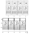
- FIG. 12 It is a figure which shows the new composite image which a cropping part cuts out and produces
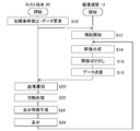
- 6 is a flowchart illustrating an example of a processing procedure in which an image display is performed in cooperation between a host terminal and an imaging apparatus in the present embodiment.
- FIG. 1 shows a configuration example of an information processing system to which this embodiment can be applied.
- the information processing system 10 includes an imaging device 12 equipped with two cameras that capture an object such as the user 1, a host terminal 20 that performs information processing according to a user's request based on the captured image, and a processing performed by the host terminal 20
- a display device 16 is provided for outputting the image data obtained as a result.
- the host terminal 20 can be connected to a network 18 such as the Internet.
- the host terminal 20, the imaging device 12, the display device 16, and the network 18 may be connected by a wired cable, or may be wirelessly connected by a wireless LAN (Local Area Network) or the like. Any two or all of the imaging device 12, the host terminal 20, and the display device 16 may be combined and integrally provided. Further, the imaging device 12 is not necessarily installed on the display device 16. Furthermore, the user 1 may not be a person, and the number is not limited.
- the imaging device 12 includes two digital video cameras, a first camera 22a and a second camera 22b, each having an imaging element such as a CCD (Charge-Coupled Device) or a CMOS (Complementary-Metal-Oxide-Semiconductor) at known intervals. It has a configuration arranged on the left and right. Each of the two digital video cameras captures an object existing in the same space from the left and right positions at the same or different frame rates. The imaging device 12 further generates a plurality of types of image data using images obtained as a result of shooting.
- CCD Charge-Coupled Device
- CMOS Complementary-Metal-Oxide-Semiconductor
- Image data captured and generated by the imaging device 12 is transmitted to the host terminal 20 in a stream format as will be described later.
- the host terminal 20 performs necessary information processing using the transmitted image data and generates an output image.
- the content of the processing performed by the host terminal 20 is not particularly limited, and is appropriately set according to the function required by the user, the content of the application, and the like.
- the host terminal 20 when performing a game in which a character that reflects the action of the user 1 as an object appears or information processing for converting the movement of the user 1 into a command input, the host terminal 20 has the same time acquired from the imaging device 12. Stereo matching is performed based on the left and right image data. A time change of the position coordinate is obtained by specifying the position coordinate of the object in the three-dimensional space of the vertical, horizontal, and depth with respect to the field of view of the camera at a predetermined rate. An output image is generated by performing processing or reflecting the image on a prepared image.
- the image of the user 1 is transmitted to the chat partner in real time via the network 18.
- the host terminal 20 may perform a face detection process and perform processing such as representing only the face area of the user 1 obtained as a result with high resolution.
- the host terminal 20 may synthesize object images such as menus and cursors for executing various applications.
- the display device 16 displays the result of the processing performed by the host terminal 20 as an image as necessary.
- the display device 16 may be a television having a display for outputting an image and a speaker for outputting sound, such as a liquid crystal television, a plasma television, a PC display, or the like.
- the imaging device 12 generates not only a moving image but also a plurality of types of image data using it. Then, by efficiently transmitting only the image data designated by the host terminal 20, an information processing system that realizes low-latency from shooting to image display and high-level processing is realized.
- the type of image generated by the imaging device 12 may be determined as appropriate according to the application, etc., but hereinafter, a case where image data representing each frame of a moving image at a plurality of resolutions will be described.
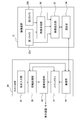
- FIG. 2 shows the configuration of the host terminal 20 and the imaging device 12.
- Each functional block shown in FIG. 2 and FIGS. 3 and 4 to be described later is configured in hardware such as a CPU (Central Processing Unit), a RAM (Random Access Memory), a ROM (Read Only Memory), and a drawing circuit.
- the software can be realized by a program that exhibits various functions such as a data input function, a data holding function, an image analysis function, and a drawing function. Therefore, it is understood by those skilled in the art that these functional blocks can be realized in various forms by hardware only, software only, or a combination thereof, and is not limited to any one.
- the host terminal 20 comprehensively controls the instruction input unit 36 that acquires an instruction input from the user, the host terminal 20 and the imaging device 12, and generates an output image, an information processing unit 38 that performs information processing according to the purpose.
- the image processing unit 40 includes a main memory 42 that stores image data from the imaging device 12, and a communication unit 44 that is an interface for requesting and acquiring image data from the imaging device 12.
- the instruction input unit 36 receives an instruction input from the user, generates a processing request signal corresponding to the instruction input, and transmits it to the information processing unit 38.
- the instruction input unit 36 is realized by the cooperation of a general input device such as a button, a keyboard, a mouse, a trackball, and a touch panel, and a processor that interprets the operation performed on the input device and generates a processing request signal. .
- the information processing unit 38 makes a request for image data to the imaging device 12 and a request for image processing to the image processing unit 40 in accordance with the processing request signal acquired from the instruction input unit 36. Further, the image data transmitted from the imaging device 12 is expanded in the main memory 42 as will be described in detail later. Further, depending on the content of the processing executed by the information processing system 10, image analysis such as stereo matching, object tracking, face detection, and gesture detection is performed using the image data transmitted from the imaging device 12.
- the image processing unit 40 uses the image developed in the main memory 42 to perform image processing in response to a request from the information processing unit 38 and generate a display image.
- the generated display image is stored in a frame memory (not shown) and is sequentially displayed on the display device 16 under the control of the information processing unit 38.
- the communication unit 44 acquires a request signal for image data to the imaging device 12 generated by the information processing unit 38 and transmits it to the imaging device 12. In response to this, the image data transmitted from the imaging device 12 is acquired and sent to the information processing unit 38.
- the imaging device 12 captures moving images and generates a plurality of types of image data, the first camera 22a and the second camera 22b, an image composition unit 30 that integrates a plurality of types of image data, and image data requested by the host terminal 20. It includes an image sending unit 32 that extracts and packetizes, and a communication unit 34 that is an interface for receiving an image data request signal from the host terminal 20 and transmitting image data.
- the first camera 22a and the second camera 22b shoot moving images of the same object from the left and right viewpoints.
- a plurality of pieces of image data having different resolutions are generated by reducing the captured frame image in stages.
- the image composition unit 30 integrates image data generated by the first camera 22a and the second camera 22b, and generates a virtual composite image as described later.
- the image sending unit 32 extracts the image data requested by the host terminal 20 from the RAW images taken by the first camera 22a and the second camera 22b and the virtual synthesized image generated by the image synthesizing unit 30 and packets. Turn into. At this time, when image data included in the virtual composite image is requested, the image is cut out by the cropping process.
- the communication unit 34 receives a request signal for image data from the host terminal 20, notifies the image transmission unit 32, acquires the packet of image data generated by the image transmission unit 32, and transmits it to the host terminal 20.
- the communication unit 34 sends the packet to the host terminal 20 according to a predetermined protocol such as USB 1.0 / 2.0 / 3.0.
- Communication with the host terminal 20 is not limited to wired communication but may be wireless communication such as wireless LAN communication such as IEEE802.11a / b / g, infrared communication such as IrDA, and the like.
- the processing performed by the imaging device 12 in the present embodiment is basically performed in units of pixels for one horizontal row of an image, and is supplied to the next functional block in that unit.
- each functional block of the image pickup apparatus 12 has only a minimum line buffer, and it is possible to perform a low delay from photographing to transmission of image data to the host terminal 20.
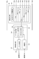
- FIG. 3 shows the configuration of the first camera 22a of the imaging device 12 in detail.
- the second camera 22b has the same configuration.
- the first camera 22a includes an image acquisition unit 102a, a demosaic unit 104a, and a pyramid filter unit 135a.
- the image acquisition unit 102a reads an image exposed by an image sensor such as a CCD or a CMOS at a predetermined frame rate. In the following description, it is assumed that this image has a width corresponding to W pixels in the horizontal direction and H pixels in the vertical direction. This image is a so-called RAW image.
- the image acquisition unit 102a sends this to the demosaic unit 104a and the image sending unit 32 every time exposure of one horizontal row of the RAW image is completed.
- the demosaic unit 104 a includes a FIFO (First In First Out) buffer 105 having a capacity for W pixels and a simple demosaic processing unit 106.
- the FIFO buffer 105 receives pixel information for one horizontal row of the RAW image, and holds it until the next horizontal row of pixels is input to the demosaic unit 104a.
- the simple demosaic processing unit 106 receives pixels for two horizontal rows, the simple demosaic processing unit 106 performs a demosaic (de-mosaic) process for generating a full-color image by complementing color information based on the peripheral pixels for each pixel. Execute.
- demosaic process As is well known to those skilled in the art, there are many methods for this demosaic process, but here, a simple demosaic process using only two horizontal rows of pixels is sufficient.
- the pixel for which the corresponding YCbCr value is to be calculated has only the G value
- the R value averages the R values adjacent to the left and right
- the G value uses the G value as it is
- the B value is the upper value.
- the B value located below is used as an RGB value, and this is substituted into a predetermined conversion formula to calculate the YCbCr value. Since such demosaic processing is well known, further detailed description is omitted. Note that the color space of the demosaic unit 104a and the image data generated in the subsequent processing is not limited to YCbCr.
- the simple demosaic processing unit 106 converts, for example, four horizontal 2 ⁇ vertical RGB pixels into a YCbCr color signal as illustrated. Then, the block composed of the four pixels is transferred to the image composition unit 30 as a 1/1 demosaiced image and also sent to the pyramid filter unit 135a.
- the pyramid filter unit 135a has a function of layering a certain image into a plurality of resolutions and outputting it.
- the pyramid filter generally includes a number of 1/4 reduction filters corresponding to the required level of resolution.
- the pyramid filter has three layers of filters of the first filter 110a to the third filter 130a. Each filter performs a process of calculating an average pixel value of four pixels by bilinear interpolation of four pixels adjacent to each other. Therefore, the image size after processing is 1 ⁇ 4 of the image before processing. It should be readily understood by those skilled in the art that the present embodiment can be similarly realized even with the number of filters other than three layers.
- one FIFO buffer 112 for W pixels is arranged corresponding to each signal of Y, Cb, and Cr.
- These FIFO buffers 112 have a role of holding YCbCr pixels for one horizontal row until the pixels for the next horizontal row are output from the simple demosaic processing unit 106.
- the pixel holding time is determined according to the line scan speed of the image sensor.
- the first filter 110a averages the pixel values of Y, Cb, and Cr for four pixels of 2 ⁇ 2 horizontal.
- the 1/1 demosaiced image becomes 1/2 in length and width, and is converted into a 1/4 size as a whole.
- the converted 1/4 demosaiced image is sent to the image synthesizing unit 30 and also passed to the second filter 120a at the next stage.
- one FIFO buffer 122 for W / 2 pixels is arranged corresponding to each of Y, Cb, and Cr signals. These FIFO buffers 122 also have a role of holding YCbCr pixels for one horizontal row until the pixels for the next horizontal row are output from the first filter 110a.
- the second filter 120a averages the pixel values of Y, Cb, and Cr for four pixels of 2 ⁇ 2 horizontal.
- the 1/4 demosaiced image becomes 1/2 in length and width, and is converted into a size of 1/16 as a whole.
- the converted 1/16 demosaiced image is sent to the image synthesizing unit 30 and also passed to the third filter 130a at the next stage.
- the same processing as described above is repeated except that W / 4 FIFO buffers 132 are arranged in the previous stage. Then, the demodulated image of 1/64 size is output to the image composition unit 30. Since the pyramid filter as described above is well known as described in Patent Document 1, further detailed explanation is omitted in this specification.
- an image output reduced by 1 ⁇ 4 is input to the image composition unit 30.
- the size of the FIFO buffer required in the preceding stage of each filter becomes smaller as it passes through the filter in the pyramid filter unit 135a.
- the number of filters is not limited to three, and may be determined as appropriate according to the required resolution width.
- the second camera 22b of the imaging device 12 has the same structure as the first camera 22a and is not illustrated, in the following description, an image acquisition unit, demosaic unit, pyramid filter unit, and first filter of the second camera 22b
- the second filter and the third filter are described with the reference numerals of the image acquisition unit 102b, the demosaic unit 104b, the pyramid filter unit 135b, the first filter 110b, the second filter 120b, and the third filter 130b, respectively.
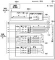
- FIG. 4 shows the configuration of the image composition unit 30 and the image transmission unit 32 in detail.
- the image composition unit 30 adjusts the output timing of the image data of each size sent from the first camera 22a and the second camera 22b to the image sending unit 32, and for adjusting the output timing.
- FIFO buffers 172a, 174a, 176a, 170b, 172b, 174b, 176b are included.
- Y, Cb, and Cr data are individually expressed and arrows for data input / output are shown for each of them. However, in order to prevent the drawing from becoming complicated, one set of these elements is shown. Represented by
- the FIFO buffers 172a, 174a, and 176a are the horizontal images of the 1/4, 1/16, and 1/64 demosaiced images sent from the first filter 110a, the second filter 120a, and the third filter 130a of the first camera 22a, respectively.
- One row of YCbCr pixel values is held.
- the FIFO buffers 172a, 174a, and 176a are buffers that hold pixel values for W / 2, W / 4, and W / 8, respectively.
- the FIFO buffers 170b, 172b, 174b, and 176b are respectively sent from the demosaic unit 104b, the first filter 110b, the second filter 120b, and the third filter 130b of the second camera 22b.
- the YCbCr pixel value for one horizontal row of the 16/64 demosaiced image is held. Accordingly, 170b, 172b, 174b, and 176b are buffers that hold pixel values for W, W / 2, W / 4, and W / 8, respectively.
- the output timing adjustment unit 140 outputs the pixel values for one horizontal row of the 1/1 demosaiced image sent from the demosaic unit 104a of the first camera 22a to the image transmission unit 32, and then stores them in the FIFO buffer 170b. The pixel values for one horizontal row of the 1/1 demosaiced image of the two cameras 22b are output.
- each of the Y, Cb, and Cr pixel values is 1 / 1, 1/4, 1/16, 1/64
- the output timing is adjusted so that a new pixel column in which the pixel columns of the demosaiced image are circulated and connected is generated.
- the processing performed by the imaging device 12 in the present embodiment is performed in raster order starting from the upper left of the image and repeating the processing from left to right in the lower direction of the image, and basically performs a horizontal row of pixels.
- the input / output of the image data from each camera to the image transmission unit 32 and the transmission of the image data to the host terminal 20 are basically performed in a stream format in which pixel values in one horizontal row of the image are connected in order from the top.
- the data output by the image compositing unit 30 is also a stream of a series of pixel values in which pixel columns of demosaiced images each representing left and right frame images at four resolutions are mixed. Therefore, strictly speaking, the result of connecting the eight demosaiced images is not generated as a two-dimensional plane image. However, as will be described in detail later, if the number of pixels in the pixel row when the connection of each demosaiced image is made a round for the stream output by the image composition unit 30 is defined as the number of pixels for one horizontal row of the image, This process is the same as that for the RAW image without the image synthesizing unit 30. As a result, the image synthesizing unit 30 substantially generates an image obtained by synthesizing the 1/1, 1/4, 1/16, 1/64 demosaiced image. Hereinafter, this virtual image is referred to as a “composite image”.
- the image sending unit 32 includes a control unit 142, a data selection unit 144, and a packetizing unit 146. Based on the request signal from the host terminal 20, the control unit 142 instructs the data selection unit 144 which of the various image data is to be transmitted as a packet.
- the control unit 142 further receives from the host terminal 20 a signal for requesting the start and end of shooting, a signal for specifying shooting conditions, and the like, and appropriately sends them to the image acquisition units 102a and 102b of the first camera 22a and the second camera 22b.
- the data selection unit 144 is a pixel sequence of the left and right RAW images input from the image acquisition unit 102a of the first camera 22a, the image acquisition unit 102b of the second camera 22b, and a pixel sequence of the composite image input from the image composition unit 30.
- the data instructed by the control unit 142 is selected, extracted, and sent to the packetizing unit 146.
- the data selection unit 144 includes a stream selection unit 148 and a cropping unit 150.
- the stream selection unit 148 selects a requested stream from the left and right RAW image and composite image streams.
- the cropping unit 150 acquires the stream of the composite image from the stream selection unit 148 and requests the requested pixel from the pixel sequence of the post-demosaic image included in the stream. Cut out columns.
- the cropping unit 150 When a plurality of demosaiced images are requested, the cropping unit 150 simultaneously cuts out pixel rows corresponding to the plurality of images. The stream is reconstructed by connecting the data of the cut out pixel strings, and is sent to the packetizing unit 146.
- the stream selection unit 148 sends the RAW image stream directly to the packetization unit 146.
- the packetizing unit 146 packetizes the stream input from the data selecting unit 144 for each size according to the protocol of the communication unit 34 and writes the packet into an internal packet buffer (not shown). For example, in the case of USB, a stream is packetized for each endpoint size.
- the communication unit 108 transfers the packet in the packet buffer to the host terminal 20 according to a predetermined communication protocol.
- FIG. 5 schematically shows the basic transition of the data format in the imaging device 12 and the host terminal 20.
- data of the entire frame image 200 having a width of W pixels in the horizontal direction and a width of H pixels in the vertical direction is transmitted from the imaging device 12 to the host terminal 20.
- generation, selection, and transmission of image data are performed in the pixel raster order, and pixel rows for one horizontal row are sequentially connected and processed in a stream format.
- the data output by the data selection unit 144 is the stream 202.
- the horizontal axis of the stream 202 represents the passage of time, and the rectangles L1, L2,..., LH constituting the stream 202 are the first column, the second column,. , H pixel data. If the data size of one pixel is d bytes, the data size of each rectangle is W ⁇ d bytes.
- the packetizing unit 146 assembles the stream 202 into packets for each predetermined size, and generates packets P1, P2, P3, P4, P5,. As a result, packets P1, P2, P3, P4, P5,... Are transmitted from the imaging device 12 to the host terminal 20 in this order.
- the host terminal 20 stores each data in the main memory 42 under the control of the information processing unit 38.
- the data of each packet is arranged in the raster order in the main memory 42 so that the horizontal number of pixels W of the original frame image 200 is set to the horizontal width, and the data is expanded to continuous addresses of W ⁇ d ⁇ H bytes.
- an image 204 obtained by restoring the frame image 200 is generated.
- the rectangle which comprises the image 204 has shown the data of each packet.
- the image processing unit 40 renders an image to be displayed on the display device 16 by processing the image 204 developed in the main memory 42 or combining it with another image under the control of the information processing unit 38.
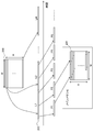
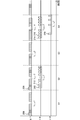
- FIG. 6 is a time chart illustrating timings at which pixel values of the 1/1 demosaiced image, the 1/4 demosaiced image, and the 1/16 demosaiced image are input from each filter of the pyramid filter unit 135a.
- time steps S1, S2, S3, S4,... are input with pixel values of the first, second, third, fourth,. Represents the period to be played.
- the highest resolution image among the images included in the composite image has the highest data generation rate in the pyramid filter unit 135a. Therefore, a period in which pixel values for one horizontal row of the image are input is set as a reference time step, and the time step is associated with a pixel row for one horizontal row of the composite image. That is, data for one horizontal row of the composite image is generated with a period in which pixel values for one horizontal row of the highest resolution image are input as a reference period.
- the upper, middle, and lower stages of the figure show the input timing of the 1/1 demosaiced image, 1/4 demosaiced image, and 1/16 demosaiced image, respectively, and one rectangle corresponds to the input for one pixel.
- a time step S1 pixel values of the first pixel row L (1/1) 1 of the 1/1 demosaiced image are sequentially input from the left pixel.
- the 1/4 demosaiced image and the 1/16 demosaiced image are not generated and thus are not input.
- step S2 pixel values of the second pixel row L (1/1) 2 of the 1/1 demosaiced image are sequentially input from the left pixel.
- the pyramid filter unit 135a uses the pixel values of the first pixel column L (1/1) 1 and the second pixel column L (1/1) 2 of the 1/1 demosaic image to 1 ⁇ 4. Since the first pixel row L (1/4) 1 of the demosaiced image is generated, the pixel value of the pixel row is also input in time step S2.
- 1/4 1 th pixel row L (1/4) of the demosaiced image pixel values input at the first leftmost period 210 is 1/1 pixel row in the first column of the demosaiced image L (1 / 1)
- the pixel value of two pixels input in the period 206 in 1 and the pixel value of two pixels input in the period 208 in the second pixel column L (1/1) 2 Generated using. Therefore, in the time step S2, the input timing of the pixel value of the pixel column L (1/4) 1 is delayed by at least two pixels from the input timing of the pixel value of the corresponding pixel of the pixel column L (1/1) 2. .
- the pixel value of the third pixel row L (1/1) 3 of the 1/1 demosaiced image is input.
- the pixel values in the second column of the 1/4 demosaiced image are not generated, and the 1/16 demosaiced image is not generated, so none of them is input.
- the next time step S4 that is, in the period in which the pixel values of the fourth pixel row L (1/1) 4 of the 1/1 demosaic image are input, as in the time step S2, 2 of the 1/4 demosaiced image.
- the pixel value of the second pixel column L (1/4) 2 is also input.
- the pyramid filter unit 135a uses the pixel values of the first pixel row L (1/4) 1 and the second pixel row L (1/4) 2 of the 1/4 demosaic image to 1/16 demosaic. Since the first pixel column L (1/16) 1 of the subsequent image is generated, the pixel value of the pixel column is also input in time step S4. For example, among the first pixel row L (1/16) 1 of the 1/16 demosaiced image, the pixel value input in the first input period 218 is the first pixel row L of the 1/4 demosaic image. (1/4) Among 1, the pixel values of two pixels input in the period 210 and the period 212 and the second pixel column L (1/4) 2 out of the period 214 and the period 216 Are generated using pixel values of two pixels.
- the input timing of the pixel column L (1/16) 1 is delayed by at least two pixels from the input timing of the pixel value of the corresponding pixel of the pixel column L (1/4) 2. Thereafter, by repeating the pixel value input for each image in the same manner, all pixel values of the 1/1 demosaiced image, the 1/4 demosaiced image, and the 1/16 demosaiced image are input to the image composition unit 30.
- the pixel values of each image are input in raster order as individual streams from the corresponding filters of the pyramid filter unit 135a of the first camera 22a and the pyramid filter unit 135b of the second camera 22b.
- the image synthesizing unit 30 connects these to form one stream and outputs the stream to the image sending unit 32.
- the synthesizing process itself is easy, but it is necessary to classify and extract data for each image in a later process, which complicates the process.
- pixel values are grouped for each image in each time step to generate a pixel row and connected in series.
- the input pixel value is only data of the 1/1 demosaiced image
- the time step S4 for example, a 1/1 demosaic image, a 1/4 demosaic image
- the data length output by the time step changes greatly, such as the data of three images of 16 demosaic images. Therefore, in the present embodiment, for an image having a time step in which data is not input, a part of the pixel value input immediately before is output using the time step, and is output at each time step. Equalize the data length.
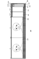
- FIG. 7 schematically shows a state in which the image composition unit 30 connects data of pixel rows of a plurality of images.
- FIG. 6 shows only the three types of demosaiced images shown in FIG. 6 connected, but actually, as will be described later, the image data from the left and right cameras are alternately displayed. It will be connected to.
- S0, S1, S2, S3,... are time steps similar to those in FIG. 6, and pixel values for one column of the 1/1 demosaiced image are input in each period.
- pixel rows output at each time step are indicated by different shaded rectangles for each image.
- the time step S1 only the pixel value of the first pixel row L (1/1) 1 of the 1/1 demosaiced image is input. It is output as it is.
- the number of pixels in the horizontal direction of the original RAW image is W
- the number of pixels for one column of the 1/1 demosaiced image is also W as shown in FIG.
- step S2 the pixel value of the second pixel row L (1/1) 2 of the 1/1 demosaiced image and the first pixel row L (1/4 ) of the 1/4 demosaiced image.
- One pixel value is input in parallel at the timing shown in FIG.
- the image compositing unit 30 temporarily stores the pixel value of the first pixel row L (1/4) 1 of the 1/4 demosaiced image in the FIFO buffer 172a, and the second row of the 1/1 demosaiced image.
- the pixel values of the pixel row L (1/1) 2 are continuously output first.
- the first pixel row L (1/4) of the 1/4 demosaiced image continues. 1 is read from the FIFO buffer 172a and output. At this time, in consideration of the amount to be output in the next time step S3, the first half portion (the left half in the image plane ) of all the pixels in the first pixel row L (1/4) 1 of the 1/4 demosaiced image Only the pixel value is output, and the rest is continuously stored in the FIFO buffer 172a.
- step S3 only the pixel value of the third pixel row L (1/1) 3 of the 1/1 demosaiced image is input.
- the image synthesizing unit 30 outputs the pixel values of the pixel columns as they are, and then continues to the second half portion that has not been output in the first pixel column L (1/4) 1 of the 1/4 demosaiced image ( The pixel value in the right half of the image plane) is read from the FIFO buffer 172a and output.
- the image synthesizing unit 30 includes pixels of the second pixel row L (1/4) 2 of the 1/4 demosaiced image and the first pixel row L (1/16) 1 of the 1/16 demosaiced image.
- the values are temporarily stored in the FIFO buffers 172a and 174a, respectively, and the pixel values of the fourth pixel column L (1/1) 4 of the 1/1 demosaiced image are continuously output first.
- the second pixel row L (1/4) of the 1/4 demosaiced image continues.
- the first half of 2 is read from the FIFO buffer 172a and output.
- the first pixel row L (1/16) 1 of the 1/16 demosaiced image is output.
- the first pixel row L (1/16) 1 of the 1/16 demosaiced image is divided into quarters, Only the pixel value of the first part is output. The rest is stored in the FIFO buffer 174a.
- step S5 only the pixel value of the fifth pixel column L (1/1) 5 of the 1/1 demosaiced image is input.
- the image compositing unit 30 outputs the pixel value of the pixel column as it is, and then continues to output the second half of the second pixel column L (1/4) 2 of the 1/4 demosaiced image that has not been output.
- the pixel value is read from the FIFO buffer 172a and output. Further, the pixel value of the second part divided by a quarter of the unoutputted data of the first pixel row L (1/16) 1 of the 1/16 demosaiced image is output.
- the pixel value of the seventh pixel row L (1/1) 7 of the 1/1 demosaiced image, the third pixel row L (1/4) of the 1/4 demosaiced image. 3 the pixel value of the last part divided by a quarter of the pixel value L (1/16) 1 of the first column of the 1/16 demosaiced image is output.
- the first pixel row L (1/4) 1 of the 1/4 demosaiced image is output in half at two time steps of time steps S2 and S3.
- the first pixel row L (1/16) 1 of the 1/16 demosaiced image is output by a quarter to the four time steps of time steps S4, S5, S6, and S7. If the number of pixels in the horizontal direction of the RAW image is W, the number of pixels for one horizontal row of the 1/4 demosaiced image and the 1/16 demosaiced image is W / 2 and W / 4, respectively.
- data of (W / 2) / 2 and (W / 4) / 4 pixels per time step is output.
- invalid data is first output as data for W pixels for which data of 1/1 demosaiced image has been output until then, and data of 1/4 demosaiced image and 1/16 demosaiced image is subsequently output.
- data for W + (W / 2) / 2 pixels which has been output data of 1/1 demosaiced image and 1/4 demosaiced image until then.
- invalid data is output, and then the data of the third part and the fourth part obtained by dividing the lowermost pixel column of the 1/16 demosaiced image by a quarter is output.
- the data output from the image composition unit 30 is an array of pixel values, but by giving the number of pixels corresponding to each time step, that is, 21 W / 16 as the number of pixels for one horizontal row, Similar to the RAW image, the image sending unit 32 handles data output at each time step as data for one column of the image.
- each time step can correspond to a vertical pixel of the image, and as a result, a composite image 220 represented by the entire rectangular area in FIG. 7 is generated.
- the 1/1 demosaiced image, the 1/4 demosaiced image, the 1/16 demosaiced image in the composite image 220 These data constitute a rectangular area. Therefore, if the locality is used, the data for each image can be easily cut out.
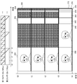
- FIG. 8 shows a composite image generated when the processing described with reference to FIG. 7 is alternately repeated for each image data output from the first camera 22a and the second camera 22b.
- the composite image 222 is a 1/1 demosaiced image 224 by the first camera 22a, a 1/1 demosaiced image 226 by the second camera 22b, a 1/4 demosaiced image 228 by the first camera 22a, and a 1 by the second camera 22b.
- 1/1 demosaiced images 224, 226 represent the face of user 1 taken from the left and right.
- Other demosaiced images that is, 1/4 demosaiced images 228 and 230, 1/16 demosaiced images 232 and 234, 1/64 demosaiced images 236 and 238, respectively, are the 1/4 demosaiced images 1 ⁇ 4. , 1/16, and 1/64, and the horizontal pixel column is divided into 1/2, 1/4, and 1/8, and the image is arranged in the vertical direction.
- the region of the pixels in the horizontal row of the 1/1 demosaiced images 224 and 226 is the horizontal area of the 1/4 demosaiced images 228 and 230. This corresponds to the region of the two columns of pixels, the region of the four columns of horizontal pixels of the 1/16 demosaiced images 232 and 234, and the region of the pixels of the horizontal column of 1/64 demosaiced images 236 and 238.
- the figure shows the width of one column of pixels wider than the actual width. For this reason, the invalid data area is widely represented. Actually, however, the invalid data area is a maximum of seven columns of pixels based on the principle described with reference to FIG. is there.
- the cropping unit 150 of the image sending unit 32 cuts out only the image data requested by the host terminal 20 from the composite image 222.
- the process performed by the cropping unit 150 is the same as a general cropping process in which a specified rectangular area in an image is cut out and an extra area is excluded.
- the processing target is not an image plane but a pixel column unit. However, if information on the number of pixels for one horizontal row of the composite image is given, the two-dimensional coordinates of the image plane correspond to the one-dimensional coordinates in the stream. It is easy to attach, and the pixels to be cut out can be specified in the same manner.
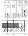
- FIG. 9 schematically shows the flow of image data in response to a request from the host terminal 20.
- the host terminal 20 transmits a data request signal for designating an area in the composite image to the imaging device 12.
- a vertical pixel range and a horizontal pixel range in the composite image 222 are designated.
- the images in the range of (Xs1, Xe1) and (Xs2, Xe2) are areas around the face of the 1/1 demosaiced image of the left and right cameras, and (Xs3, Xe3) is the 1/4 demosaic of one camera
- the entire image, (Xs4, Xe4) is the entire 1/16 demosaiced image of one camera.
- the cropping unit 150 cuts out a designated area from the composite image input by the image composition unit 30 for each horizontal pixel row. Specifically, only the pixel columns in the range of (Xs1, Xe1), (Xs2, Xe2), (Xs3, Xe3), (Xs4, Xe4) are cut out from the pixel column at the position of Ys, and are sequentially sent to the packetizing unit 146. Send it out. Next, similarly to the Ys + 1 pixel column, the Ys + 2 pixel column,..., A pixel column in the same range is cut out and sent to the packetizing unit 146. The packetizing unit 146 connects the extracted pixel rows into a stream and sequentially packetizes them.
- the image data received by the host terminal 20 becomes a stream of a new composite image 240 consisting only of the clipped area.
- the information processing unit 38 of the host terminal 20 cuts it into individual images and develops them into consecutive addresses in the main memory 42.
- the main memory 42 stores the images 242 and 244 around the face among the left and right 1/1 demosaic images, the overall image 246 of the 1/4 demosaiced image, and the overall image 248 of the 1/16 demosaiced image. Is done.
- the information processing unit 38 may develop the composite image 240 as it is in the main memory 42 and distinguish it at the stage of use for image processing or the like.
- the host terminal 20 can simultaneously request a plurality of image types and a specific area among them by designating an area in the composite image. Then, the cropping unit 150 extracts a plurality of pieces of image data at the same time by extracting pixel values in a specified range for each column of pixels, and generates a new stream including only necessary image data.
- the host terminal 20 has a common vertical range for a plurality of areas designated at the same time.
- the four specified areas all have a vertical range of (Ys, Ye).
- the host terminal 20 can easily develop the acquired stream into individual images based on the requested number of pixels in the horizontal direction of each region.
- FIG. 10 shows the transition of the composite image generated by the image compositing unit 30 when the first camera 22a and the second camera 22b equipped with a rolling shutter are photographed at frame rates of 60 fps and 15 fps, respectively.
- the thick line at the top of the figure shows the position of the scan line of each camera over time, and the second camera 22b captures one frame at the same shutter speed every time the first camera 22a captures four frames.
- This frame rate is merely an example, and any condition may be used as long as the second camera 22b captures one frame each time the first camera 22a captures a predetermined number of frames of 2 or more.
- the first imaging period (time t0 to t1), the second imaging period (time t1 to t2), and the third imaging period (time t2 to t3) in which only the first camera 22a performs imaging are shown in FIG.
- the 1/1 demosaiced image 250, the 1/4 demosaiced image 252, the 1/16 demosaiced image 254, and the 1/64 demosaiced image 256 of the frame captured by the first camera 22a are sequentially displayed in the image composition unit. 30.
- the image composition unit 30 also adds invalid data corresponding to each demosaiced image to the stream at the timing of outputting the data from the second camera 22b even during a period in which no image data is input from each filter of the second camera 22b. .
- the number of pixels in one horizontal row of the composite image does not change in any period, and the same type of image is arranged at the same position.
- there is a one-to-one correspondence between the type of image data and the area on the composite image, and the area designation of the host terminal 20 can be simplified. Such image data transmission is repeated in subsequent periods.
- FIG. 11 shows a new composite image generated by the cropping unit 150 cut out and generated under the shooting conditions shown in FIG. 10 and an image stored in the main memory 42 of the host terminal 20.
- the host terminal 20 requests image data by designating the area shown in FIG.
- Each time shown on the vertical axis represents the time at which the original frame was photographed in correspondence with FIG. 10, and the time until cut-out processing and storage in the main memory 42 is omitted.
- the host terminal 20 When the host terminal 20 receives such image data in a stream format, the host terminal 20 develops it in the main memory 42. If the portion that was invalid data at this time is discarded, the image 288 of the area around the face of the 1/1 demosaiced image of the frame captured by the first camera 22a in the main memory 42 at time t1, 1/4 demosaic. The storage of the entire image 290 of the after image and the entire image 292 of the 1/16 demosaiced image is completed. The same applies to the second imaging cycle (from time t1 to t2) and the third imaging cycle (from time t2 to t3).
- the stereo matching is performed once every four frames in the host terminal 20 to confirm the position of the target object such as the user 1, and the resolution is increased using the 1/1 demosaiced image only for the face area.
- the image after 1/4 demosaicing or the whole image of 1/16 demosaicing can be displayed on the display device 16.
- the result of the stereo matching is fed back to the area designation at the time of requesting the image data to the imaging device 12, the zoom mechanism or the pan tilter control mechanism of the imaging device 12, and the like.
- the entire image showing only the vicinity in detail can always be displayed with the minimum image data transfer.
- change the exposure time of the two cameras use an image with a long exposure time and sufficient brightness for display, and use the two cameras separately so that an image with a low brightness and a high frame rate is used for image analysis. Also good.
- FIG. 12 shows a case where, among the shooting conditions shown in FIG. 10, the shutter speed of the second camera 22b is set to 1/4, and the second camera 22b takes one frame over the time taken for the first camera 22a to take four frames. This shows the transition of the composite image.
- the data for one column of the 1/1 demosaiced image output from the second camera 22b does not change until the data for the four columns of the 1/1 demosaiced image is output from the first camera 22a.
- the data output from the second camera 22b is performed at a cycle four times the data output of the first camera 22a.
- the frame rate and the shutter speed are examples, and the frame rate and the shutter speed of the second camera 22b may be 1 / N (N is a natural number of 2 or more) of the first camera 22a.
- the 1/1 demosaiced image 302 of the frame captured by the second camera 22b is extended four times in the vertical direction in the composite image corresponding to the pixels in the vertical direction. Strictly speaking, the image has the same pixel value for every four columns of pixels.
- the first shooting period time t0 to t1
- the second shooting period time t1 to t2
- the third shooting period time t2 to t3
- the mouth part in the fourth shooting period (time t3 to t4)
- the shoulder portion is output, and the 1/4 demosaiced image, 1/16 demosaiced image, and 1/64 demosaiced image are also reduced in each shooting period. It becomes.
- FIG. 13 shows a new composite image generated by the cropping unit 150 by clipping under the shooting conditions shown in FIG. 12 and an image stored in the main memory 42 of the host terminal 20.
- the way of illustration is the same as FIG.
- / 1 part of the area around the face 306 in the demosaiced image the entire image 308 of the 1/4 demosaiced image of the frame captured by the first camera 22a, and the data of the overall image 310 of the 1/16 demosaiced image are 1 Extracted for each column.
- the host terminal 20 develops the image data in the main memory 42 as in FIG. 11, but the 1/1 demosaiced image portion of the frame captured by the second camera 22 b in the stream transmitted from the image capturing device 12. , Discarding 3 columns out of 4 columns of data holding the same pixel value.
- the development of the image 312 in the area around the face in the 1/1 demosaiced image of the frame shot by the second camera 22b is completed.
- the images in the main memory 42 in FIGS. 11, 13, and 15 are shown at the timing when only the development is completed, but the 1/1 demosaiced image of the frame captured by the second camera 22 b in FIG. 13. Is gradually stored immediately after time t0.
- Other images in the main memory 42 are the same as those in FIG.
- FIG. 14 shows the transition of the composite image when the frame rate of the second camera 22b is 60 fps, and the first camera 22a captures an angle of view smaller than the second camera 22b at a frame rate of 240 fps higher than that of the second camera 22b.
- the first camera 22a captures the eye part of the user 1 four times while the second camera 22b captures one frame.
- the 1/1 demosaiced image 314 of the frame of the first camera 22a has a vertical direction as shown in FIG.
- the image becomes a series of four.
- the 1/4 demosaiced image, 1/16 demosaiced image, and 1/64 demosaiced image of the frame of the first camera 22a are also reduced images in each shooting cycle.
- FIG. 15 shows a new composite image generated by the cropping unit 150 by cutting out under the shooting conditions shown in FIG. 14 and an image stored in the main memory 42 of the host terminal 20.
- the way of illustration is the same as FIG. However, in the case of the figure, the 1/1 demosaiced image 316 of the high frame rate eye imaged by the first camera 22a, the 1/1 demosaiced image 318 of the frame imaged by the second camera, and the 1/4 demosaic.
- the rear image 320 is cut out.
- the development of these images is completed in the main memory 42 of the host terminal 20 corresponding to the end time of each shooting cycle.
- the face and eyelid movements are accurately tracked with high temporal resolution using a 1/1 demosaiced image of the eye part to detect facial expressions and gestures, and only the face area is 1/1 demosaiced.
- the present invention can be used in a situation where the entire image of the 1/4 demosaiced image is displayed on the display device 16 with the resolution increased using the image.
- the display image can be processed according to the detected facial expression and gesture. If the image is displayed on another user's display device via a network, video chat or the like in which decoration or animation appears in the image depending on the expression can be realized.
- the eye portion is photographed at a high frame rate, but a user's hand, a marker held by the user, or the like may be photographed to be a tracking target. In this case, the movement of the hand or marker can be used as an operation input means for information processing.
- FIG. 16 is a flowchart illustrating an example of a processing procedure in which the host terminal 20 and the imaging device 12 cooperate to display an image.
- the flowchart of FIG. 16 is started when the user inputs an application activation instruction to the host terminal 20.
- each step is represented by a rectangle connected in series, but these steps are executed in parallel for each pixel column and each frame during the period of capturing a moving image.
- the host terminal 20 designates initial conditions and necessary image data set in an application program or the like, and issues a photographing start instruction and a data transmission request to the imaging device 12 (S10).
- the initial conditions are the resolution, frame rate, shutter speed, angle of view, and the like of moving images taken by the two cameras of the imaging device 12.
- the resolution and frame rate of a moving image captured by the camera may be changed by changing the condition setting for exposure by the image sensor, or by adjusting the thinning of data from the image sensor at a later stage. Good.
- Necessary image data is specified by the area of the composite image as described above, but as an initial value, a 1/1 demosaiced image of an area considered to be present by the user or an entire image of any resolution is specified.
- the first camera 22a and the second camera 22b of the imaging device 12 that have received the initial condition specification and the image data request start capturing a moving image under the initial condition (S12).
- the RAW image acquired by each camera is processed by the demosaic units 104a and 104b and the pyramid filter units 135a and 170b for each pixel column, and the demosaiced image of each layer output at each time step is synthesized by the image synthesis unit 30. (S14).
- the image sending unit 32 cuts out only the image data specified in S10 from the synthesized image, packetizes it as a stream, and sends it to the host terminal 20 (S16, S18). If RAW image data is requested, the process of S16 may be omitted.
- the information processing unit 38 of the host terminal 20 that has received the data develops the transmitted stream as an image in the main memory 42 (S20).
- the information processing unit 38 performs processing according to the application being executed using the developed image (S22).
- the image processing unit 40 is requested to perform image processing, and the image processing unit 40 reads out an image from the main memory 42 and performs processing and composition. Since the image data developed in the main memory 42 is the same as general image data, it can be read out as a texture.
- the information processing unit 38 may perform image analysis processing such as stereo matching, tracking, face detection, and gesture detection and reflect the result in the display image. In this way, a display image is generated and displayed on the display device 16 (S24, S26). Further, the information processing unit 38 may specify the region of the object by the above image analysis in S22 and change the requested image data. In this case, the cropping unit 150 of the imaging device 12 changes the cutout region according to the designation at the timing of processing a new image frame. By repeating the processing from S14 to S26, a moving image using an image captured by the imaging device 12 can be displayed on the display device 16.
- image analysis processing such as stereo matching, tracking, face detection, and gesture detection
- the captured moving image has multiple resolutions within the camera.
- Data A stream in which pixel values are connected in the raster order of pixels for each image type and resolution. Then, a part thereof is transmitted according to the request of the host terminal, and a frame image is constructed in the memory of the host terminal.
- the memory size to be provided in the camera can be minimized by sequentially performing the processing in the state of the pixel row without developing the frame image inside the camera.
- the entire system can display an image corresponding to movement with low delay.
- image data of multiple resolutions are connected to each row of pixel values and included in one stream.
- the rate at which the “pixel value for one column” is generated differs depending on the resolution
- the low-resolution image in which the data is generated at a low rate is evenly included in the stream including the period in which the data is not generated. To distribute. This makes the data size to be processed and transmitted per unit time approximately equal, making it easy to estimate the time required for output, the transmission bandwidth to be used, and the time required for transmission, and a sudden increase in data size. This reduces the possibility of squeezing the transmission band.
- each of the images to be synthesized forms a rectangular area in the synthesized image, so by specifying the area in the synthesized image, by general image processing called cropping, Data of a plurality of images mixed in one stream can be easily separated.
- a plurality of areas in the composite image are simultaneously cut out by cropping and transmitted as a stream in a state where a plurality of types of image data are mixed.
- the actual processing can be performed while maintaining the rectangular region of the composite image even if the unit is a pixel column unit. Can be easily done.
- the data size included in the stream is equalized according to the generation rate of the image data of each size, so the transfer delay due to the increased bit rate Is less likely to occur.
- a virtual composite image is generated by mixing a plurality of image data representing frames of a stereo image at different resolutions in a stream.
- the bit rate can be equalized by devising the arrangement of the images with different data generation rates in the composite image.
- the image included in the composite image is not limited to this, and a plurality of types of images generated at each time can be similarly combined, cut out, and transmitted to the host terminal.
- a pair of stereo images with one resolution may be used, or a depth image in which the position of the target in the depth direction is displayed on the image plane, an inter-frame difference image, or the like may be mixed.
- the imaging apparatus is provided with a mechanism for performing stereo matching processing and inter-frame difference processing.
- a plurality of types of images generated from a single frame image instead of a stereo image may be used.
- a plurality of types of images generated from a single frame image instead of a stereo image may be used.
- the host terminal can acquire a plurality of types of images with a low delay only by specifying a region without providing a plurality of transmission paths.
- 10 information processing system 12 imaging device, 16 display device, 20 host terminal, 22a first camera, 22b second camera, 30 image compositing unit, 32 image sending unit, 34 communication unit, 36 instruction input unit, 38 information processing unit , 40 image processing unit, 42 main memory, 44 communication unit, 102a image acquisition unit, 104a demosaic unit, 110a first filter, 120a second filter, 130a third filter, 135a pyramid filter unit, 140 output timing adjustment unit, 142 Control unit, 144 data selection unit, 146 packetization unit, 148 stream selection unit, 150 cropping unit.
- the present invention can be used for information processing apparatuses and information processing systems such as computers, game apparatuses, cameras, and image display apparatuses.
Landscapes
- Engineering & Computer Science (AREA)
- Multimedia (AREA)
- Signal Processing (AREA)
- Studio Devices (AREA)
- Image Processing (AREA)
- Testing, Inspecting, Measuring Of Stereoscopic Televisions And Televisions (AREA)
- Two-Way Televisions, Distribution Of Moving Picture Or The Like (AREA)
Abstract
Description
図1は本実施の形態を適用できる情報処理システムの構成例を示す。情報処理システム10は、ユーザ1などの対象物を撮影する2つのカメラを搭載した撮像装置12、撮影した画像に基づき、ユーザの要求に応じた情報処理を行うホスト端末20、ホスト端末20が処理した結果得られた画像データを出力する表示装置16を含む。またホスト端末20はインターネットなどのネットワーク18と接続可能とする。
Claims (13)
- 対象物を撮影して得られる動画像の各フレーム画像から複数の画像のデータを生成し、横一列の画素ごとにストリームとして順次出力する画像データ生成部と、
前記画像データ生成部から出力された前記複数の画像のデータを、画像の横一列分の画素列またはそれより小さい範囲の画素列ごとに循環して接続し、ストリームとして出力することにより、接続が一巡したときの画素列を横一列分の画素列とする、前記複数の画像を含む仮想的な合成画像を生成する画像合成部と、
接続したホスト端末から、前記仮想的な合成画像における、縦方向の範囲を同じとした複数の矩形領域を指定するデータの送信要求を受け付け、前記画像合成部が出力した前記仮想的な合成画像の画素列ごとに、指定された領域を切り出して接続し、新たなストリームとして前記ホスト端末に送信する画像送出部と、
を備えることを特徴とする動画像撮影装置。 - 前記動画像撮影装置は、対象物を既知の距離を隔てた左右の視点から撮影する2つのカメラをさらに備え、
前記画像データ生成部は、前記2つのカメラが撮影した左右のフレーム画像をそれぞれ多段階で縮小することにより、異なる解像度の複数の画像のデータを左右のフレーム画像について生成することを特徴とする請求項1に記載の動画像撮影装置。 - 前記2つのカメラのうち第2のカメラは、第1のカメラが2以上の所定の数のフレームを撮影するごとに同じシャッタースピードで1フレーム撮影し、
前記画像合成部は、前記第1のカメラが撮影したフレーム画像から生成された画像のデータのみが前記画像データ生成部から出力される期間、前記第2のカメラが撮影したフレーム画像から生成された画像のデータに代えて無効データを接続してストリームに加え、
前記画像送出部は、無効データの有無に関わらず指定された領域を切り出すことを特徴とする請求項2に記載の動画像撮影装置。 - 前記2つのカメラのうち第2のカメラは、第1のカメラのフレームレートおよびシャッタースピードの1/N(Nは2以上の自然数)のフレームレートおよびシャッタースピードで撮影し、
前記画像合成部は、前記第1のカメラが撮影したフレーム画像から生成された画像のデータの横N列の画素列のぞれぞれに対し、前記第2のカメラが撮影したフレーム画像から生成された画像のデータの横一列の画素列をN回接続することを特徴とする請求項2に記載の動画像撮影装置。 - 前記2つのカメラのうち第1のカメラは、縦方向の長さが第2のカメラの1/N(Nは2以上の自然数)の撮影範囲をN倍のフレームレートで撮影し、
前記画像合成部は、前記第2のカメラが撮影した1フレーム分の画像のデータの画素列に対し、前記第2のカメラが撮影したNフレーム分の画像のデータの画素列をそれぞれ接続することを特徴とする請求項2に記載の動画像撮影装置。 - 前記画像データ生成部は、各フレーム画像を縦横双方向に1/2ずつ縮小することにより、異なる解像度の複数の画像のデータを生成し、
前記画像合成部は、縮小率が1/2n(nは整数)の画像の横一列分の画素列を1/2n分割してなる画素列ごとに循環して接続することを特徴とする請求項1から5のいずれかに記載の動画像撮影装置。 - 前記画像データ生成部は、横一列分の画素列を処理単位として前記複数の画像のデータを並列に生成したうえ、順次、前記画像合成部に出力し、
前記画像合成部は、前記画像データ生成部から出力された画像のデータを、逐次接続してストリームとして出力することを特徴とする請求項1から5のいずれかに記載の動画像撮影装置。 - 前記画像合成部は、前記合成画像において前記複数の画像がそれぞれ矩形の領域を構成するように画像のデータを接続することを特徴とする請求項7に記載の動画撮影装置。
- 対象物を撮影して動画像のデータを生成する動画像撮影装置と、当該動画像撮影装置から動画像のデータの一部を取得し、それを利用して所定の画像処理を行ったうえ画像を表示するホスト端末と、を備えた情報処理システムであって、
前記動画像撮影装置は、
動画像の各フレーム画像から複数の画像のデータを生成し、横一列の画素ごとにストリームとして順次出力する画像データ生成部と、
前記画像データ生成部から出力された前記複数の画像のデータを、画像の横一列分の画素列またはそれより小さい範囲の画素列ごとに循環して接続し、ストリームとして出力することにより、接続が一巡したときの画素列を横一列分の画素列とする、前記複数の画像を含む仮想的な合成画像を生成する画像合成部と、
接続したホスト端末から、前記仮想的な合成画像における、縦方向の範囲を同じとした複数の矩形領域を指定するデータの送信要求を受け付け、前記画像合成部が出力した前記仮想的な合成画像の画素列ごとに、指定された領域を切り出して接続し、新たなストリームとして前記ホスト端末に送信する画像送出部と、を備え、
前記ホスト端末は、
前記動画像撮影装置において生成される複数の画像のデータのうち少なくとも2つの画像のデータに対応する、前記仮想的な合成画像における矩形領域を、縦方向の範囲を同じとして指定してデータの送信を要求するデータ要求部と、
前記動画像撮影装置から送信されたストリームを、指定した各矩形領域の横方向の長さに基づき個別の画像のデータに分別し、2次元の画像としてメモリに展開するデータ展開部と、
を備えることを特徴とする情報処理システム。 - 対象物を撮影して得られる動画像の各フレーム画像から生成した複数の画像をそれぞれ所定の矩形領域に配置した合成画像を生成する動画像撮影装置に対し、少なくとも2つの画像のデータに対応する、前記合成画像における矩形領域を、縦方向の範囲を同じとして指定してデータの送信を要求するデータ要求部と、
要求に従って前記動画像撮影装置から送信された、指定した複数の矩形領域の画素値を画素列ごとに循環して接続したストリームの状態の画像データを、指定した各矩形領域の横方向の長さに基づき個別の画像のデータに分別し、2次元の画像としてメモリに展開するデータ展開部と、
前記2次元の画像を利用して所定の画像処理を行ったうえ画像を表示するデータ処理部と、
を備えることを特徴とする情報処理装置。 - 動画像撮影装置が行う画像データ処理方法であって、
対象物を撮影して得られる動画像の各フレーム画像から複数の画像のデータを生成し、横一列の画素ごとにストリームとして順次出力するステップと、
前記出力された前記複数の画像のデータを、画像の横一列分の画素列またはそれより小さい範囲の画素列ごとに循環して接続し、ストリームとして出力することにより、接続が一巡したときの画素列を横一列分の画素列とする、前記複数の画像を含む仮想的な合成画像を生成するステップと、
接続したホスト端末から、前記仮想的な合成画像における、縦方向の範囲を同じとした複数の矩形領域を指定するデータの送信要求を受け付け、前記仮想的な合成画像の画素列ごとに、指定された領域を切り出して接続し、新たなストリームとして前記ホスト端末に送信するステップと、
を含むことを特徴とする画像データ処理方法。 - 対象物を撮影して得られた動画像の各フレーム画像から複数の画像のデータを生成し、横一列の画素ごとにストリームとして順次出力する撮像装置のコンピュータに、
前記出力された前記複数の画像のデータを、画像の横一列分の画素列またはそれより小さい範囲の画素列ごとに循環して接続し、ストリームとして出力することにより、接続が一巡したときの画素列を横一列分の画素列とする、前記複数の画像を含む仮想的な合成画像を生成する機能と、
接続したホスト端末から、前記仮想的な合成画像における、縦方向の範囲を同じとした複数の矩形領域を指定するデータの送信要求を受け付け、前記仮想的な合成画像の画素列ごとに、指定された領域を切り出して接続し、新たなストリームとして前記ホスト端末に送信する機能と、
を実現させることを特徴とするコンピュータプログラム。 - 対象物を撮影して得られた動画像の各フレーム画像から複数の画像のデータを生成し、横一列の画素ごとにストリームとして順次出力する撮像装置のコンピュータに、
前記出力された前記複数の画像のデータを、画像の横一列分の画素列またはそれより小さい範囲の画素列ごとに循環して接続し、ストリームとして出力することにより、接続が一巡したときの画素列を横一列分の画素列とする、前記複数の画像を含む仮想的な合成画像を生成する機能と、
接続したホスト端末から、前記仮想的な合成画像における、縦方向の範囲を同じとした複数の矩形領域を指定するデータの送信要求を受け付け、前記仮想的な合成画像の画素列ごとに、指定された領域を切り出して接続し、新たなストリームとして前記ホスト端末に送信する機能と、
を実現させることを特徴とするコンピュータプログラムを記録した記録媒体。
Priority Applications (5)
| Application Number | Priority Date | Filing Date | Title |
|---|---|---|---|
| EP12818415.7A EP2739046B1 (en) | 2011-07-25 | 2012-05-31 | Moving image capture device, information processing system, information processing device, and image data processing method |
| CN201280045359.XA CN103797790B (zh) | 2011-07-25 | 2012-05-31 | 移动图像捕获设备、信息处理系统、信息处理设备、以及图像数据处理方法 |
| AU2012288349A AU2012288349B2 (en) | 2011-07-25 | 2012-05-31 | Moving image capture device, information processing system, information processing device, and image data processing method |
| CA2842301A CA2842301C (en) | 2011-07-25 | 2012-05-31 | Moving image capturing device, information processing system, information processing device, and image data processing method |
| US14/232,985 US9736458B2 (en) | 2011-07-25 | 2012-05-31 | Moving image capturing device, information processing system, information processing device, and image data processing method |
Applications Claiming Priority (2)
| Application Number | Priority Date | Filing Date | Title |
|---|---|---|---|
| JP2011162334A JP5701707B2 (ja) | 2011-07-25 | 2011-07-25 | 動画像撮影装置、情報処理システム、情報処理装置、および画像データ処理方法 |
| JP2011-162334 | 2011-07-25 |
Publications (1)
| Publication Number | Publication Date |
|---|---|
| WO2013014844A1 true WO2013014844A1 (ja) | 2013-01-31 |
Family
ID=47600722
Family Applications (1)
| Application Number | Title | Priority Date | Filing Date |
|---|---|---|---|
| PCT/JP2012/003575 Ceased WO2013014844A1 (ja) | 2011-07-25 | 2012-05-31 | 動画像撮影装置、情報処理システム、情報処理装置、および画像データ処理方法 |
Country Status (8)
| Country | Link |
|---|---|
| US (1) | US9736458B2 (ja) |
| EP (1) | EP2739046B1 (ja) |
| JP (1) | JP5701707B2 (ja) |
| CN (1) | CN103797790B (ja) |
| AU (1) | AU2012288349B2 (ja) |
| CA (1) | CA2842301C (ja) |
| TW (1) | TWI495346B (ja) |
| WO (1) | WO2013014844A1 (ja) |
Cited By (1)
| Publication number | Priority date | Publication date | Assignee | Title |
|---|---|---|---|---|
| CN104125450A (zh) * | 2013-04-26 | 2014-10-29 | 索尼电脑娱乐公司 | 图像拾取装置、信息处理系统和图像数据处理方法 |
Families Citing this family (29)
| Publication number | Priority date | Publication date | Assignee | Title |
|---|---|---|---|---|
| US9537706B2 (en) | 2012-08-20 | 2017-01-03 | Plentyoffish Media Ulc | Apparatus, method and article to facilitate matching of clients in a networked environment |
| US11568008B2 (en) | 2013-03-13 | 2023-01-31 | Plentyoffish Media Ulc | Apparatus, method and article to identify discrepancies between clients and in response prompt clients in a networked environment |
| US9672289B1 (en) | 2013-07-23 | 2017-06-06 | Plentyoffish Media Ulc | Apparatus, method and article to facilitate matching of clients in a networked environment |
| US9300869B2 (en) * | 2013-10-24 | 2016-03-29 | Fujitsu Limited | Reduction of spatial resolution for temporal resolution |
| US9870465B1 (en) | 2013-12-04 | 2018-01-16 | Plentyoffish Media Ulc | Apparatus, method and article to facilitate automatic detection and removal of fraudulent user information in a network environment |
| TWI502162B (zh) * | 2014-03-21 | 2015-10-01 | Univ Feng Chia | 雙影像導引追瞄之射擊系統與方法 |
| US9706114B2 (en) * | 2014-09-12 | 2017-07-11 | Sony Corporation | Image pickup apparatus, information processing apparatus, display apparatus, information processing system, image data sending method, image displaying method, and computer program |
| US9686338B1 (en) | 2014-10-24 | 2017-06-20 | Amazon Technologies, Inc. | Streaming content adjustment based on camera feedback |
| US10212319B1 (en) * | 2014-11-04 | 2019-02-19 | Amazon Technologies, Inc. | Camera positioning fixture |
| US20160140733A1 (en) * | 2014-11-13 | 2016-05-19 | Futurewei Technologies, Inc. | Method and systems for multi-view high-speed motion capture |
| US10460464B1 (en) | 2014-12-19 | 2019-10-29 | Amazon Technologies, Inc. | Device, method, and medium for packing recommendations based on container volume and contextual information |
| KR101686143B1 (ko) * | 2014-12-30 | 2016-12-13 | 채수한 | 영상 처리 장치 및 영상 처리 방법 |
| KR20170013083A (ko) * | 2015-07-27 | 2017-02-06 | 엘지전자 주식회사 | 이동단말기 및 그 제어방법 |
| US20170094171A1 (en) * | 2015-09-28 | 2017-03-30 | Google Inc. | Integrated Solutions For Smart Imaging |
| JP6218787B2 (ja) * | 2015-09-29 | 2017-10-25 | 株式会社ソニー・インタラクティブエンタテインメント | 撮像装置、情報処理装置、表示装置、情報処理システム、画像データ送出方法、および画像表示方法 |
| US10757344B2 (en) | 2016-07-01 | 2020-08-25 | Maxell, Ltd. | Imaging apparatus, imaging method and imaging program |
| JP6743604B2 (ja) * | 2016-09-12 | 2020-08-19 | ソニー株式会社 | マルチカメラシステム、カメラ、カメラの処理方法、確認装置および確認装置の処理方法 |
| US10078708B2 (en) * | 2016-11-15 | 2018-09-18 | Tealium Inc. | Shared content delivery streams in data networks |
| CN109190533B (zh) * | 2018-08-22 | 2021-07-09 | Oppo广东移动通信有限公司 | 图像处理方法和装置、电子设备、计算机可读存储介质 |
| WO2020061104A1 (en) | 2018-09-18 | 2020-03-26 | Intuitive Surgical Operations, Inc. | Method and system for enhanced image sensor timing |
| JP6705534B2 (ja) * | 2018-10-19 | 2020-06-03 | ソニー株式会社 | センサ装置、信号処理方法 |
| CN113475054A (zh) | 2019-02-27 | 2021-10-01 | 富士胶片株式会社 | 摄像装置、摄像装置的图像数据处理方法及程序 |
| CN110475065B (zh) * | 2019-08-19 | 2021-03-16 | 北京字节跳动网络技术有限公司 | 图像处理的方法、装置、电子设备及存储介质 |
| CN111013150B (zh) * | 2019-12-09 | 2020-12-18 | 腾讯科技(深圳)有限公司 | 一种游戏视频剪辑方法、装置、设备及存储介质 |
| CN112218160A (zh) * | 2020-10-12 | 2021-01-12 | 北京达佳互联信息技术有限公司 | 视频转换方法及装置和视频转换设备及存储介质 |
| JP2022072908A (ja) * | 2020-10-30 | 2022-05-17 | パナソニックIpマネジメント株式会社 | 生体情報取得装置、生体認証装置および生体情報取得方法 |
| JP7468391B2 (ja) * | 2021-02-09 | 2024-04-16 | 株式会社Jvcケンウッド | 撮像装置および撮像処理方法 |
| US11823430B2 (en) * | 2021-07-16 | 2023-11-21 | Arm Limited | Video data processing |
| WO2025047420A1 (ja) * | 2023-08-30 | 2025-03-06 | ソニーセミコンダクタソリューションズ株式会社 | 撮像装置、および撮像方法 |
Citations (4)
| Publication number | Priority date | Publication date | Assignee | Title |
|---|---|---|---|---|
| JPH11234654A (ja) * | 1998-02-19 | 1999-08-27 | Fujitsu Ltd | 多画面合成方法及び多画面合成装置 |
| EP0999518A1 (en) | 1998-05-19 | 2000-05-10 | Sony Computer Entertainment Inc. | Image processing apparatus and method, and providing medium |
| JP2006013875A (ja) * | 2004-06-25 | 2006-01-12 | Victor Co Of Japan Ltd | 画像表示システム |
| JP2007053491A (ja) * | 2005-08-16 | 2007-03-01 | Canon Inc | データ処理装置及びデータ処理方法 |
Family Cites Families (7)
| Publication number | Priority date | Publication date | Assignee | Title |
|---|---|---|---|---|
| JP4360930B2 (ja) * | 2004-02-17 | 2009-11-11 | 三菱電機株式会社 | 画像表示装置 |
| US20070102622A1 (en) * | 2005-07-01 | 2007-05-10 | Olsen Richard I | Apparatus for multiple camera devices and method of operating same |
| JP5145179B2 (ja) | 2008-09-16 | 2013-02-13 | 株式会社日立ソリューションズ | 光学式読取りコードを用いた本人確認システム |
| JP5325745B2 (ja) | 2009-11-02 | 2013-10-23 | 株式会社ソニー・コンピュータエンタテインメント | 動画像処理プログラム、装置および方法、動画像処理装置を搭載した撮像装置 |
| US8339470B2 (en) * | 2009-11-30 | 2012-12-25 | Indian Institute Of Technology Madras | Method and system for generating a high resolution image |
| JP2011135246A (ja) * | 2009-12-24 | 2011-07-07 | Sony Corp | 画像処理装置、撮像装置、および画像処理方法、並びにプログラム |
| JP5629642B2 (ja) * | 2011-05-19 | 2014-11-26 | 株式会社ソニー・コンピュータエンタテインメント | 動画像撮影装置、情報処理システム、情報処理装置、および画像データ処理方法 |
-
2011
- 2011-07-25 JP JP2011162334A patent/JP5701707B2/ja active Active
-
2012
- 2012-05-31 US US14/232,985 patent/US9736458B2/en active Active
- 2012-05-31 CA CA2842301A patent/CA2842301C/en active Active
- 2012-05-31 EP EP12818415.7A patent/EP2739046B1/en active Active
- 2012-05-31 AU AU2012288349A patent/AU2012288349B2/en active Active
- 2012-05-31 WO PCT/JP2012/003575 patent/WO2013014844A1/ja not_active Ceased
- 2012-05-31 CN CN201280045359.XA patent/CN103797790B/zh active Active
- 2012-07-25 TW TW101126855A patent/TWI495346B/zh active
Patent Citations (4)
| Publication number | Priority date | Publication date | Assignee | Title |
|---|---|---|---|---|
| JPH11234654A (ja) * | 1998-02-19 | 1999-08-27 | Fujitsu Ltd | 多画面合成方法及び多画面合成装置 |
| EP0999518A1 (en) | 1998-05-19 | 2000-05-10 | Sony Computer Entertainment Inc. | Image processing apparatus and method, and providing medium |
| JP2006013875A (ja) * | 2004-06-25 | 2006-01-12 | Victor Co Of Japan Ltd | 画像表示システム |
| JP2007053491A (ja) * | 2005-08-16 | 2007-03-01 | Canon Inc | データ処理装置及びデータ処理方法 |
Non-Patent Citations (1)
| Title |
|---|
| See also references of EP2739046A4 |
Cited By (1)
| Publication number | Priority date | Publication date | Assignee | Title |
|---|---|---|---|---|
| CN104125450A (zh) * | 2013-04-26 | 2014-10-29 | 索尼电脑娱乐公司 | 图像拾取装置、信息处理系统和图像数据处理方法 |
Also Published As
| Publication number | Publication date |
|---|---|
| EP2739046A4 (en) | 2015-04-01 |
| AU2012288349A1 (en) | 2014-02-27 |
| EP2739046B1 (en) | 2020-06-10 |
| CN103797790B (zh) | 2016-08-17 |
| EP2739046A1 (en) | 2014-06-04 |
| TWI495346B (zh) | 2015-08-01 |
| AU2012288349B2 (en) | 2015-11-26 |
| CA2842301A1 (en) | 2013-01-31 |
| US9736458B2 (en) | 2017-08-15 |
| CN103797790A (zh) | 2014-05-14 |
| TW201320748A (zh) | 2013-05-16 |
| US20140152773A1 (en) | 2014-06-05 |
| JP5701707B2 (ja) | 2015-04-15 |
| JP2013026978A (ja) | 2013-02-04 |
| CA2842301C (en) | 2016-05-10 |
Similar Documents
| Publication | Publication Date | Title |
|---|---|---|
| JP5701707B2 (ja) | 動画像撮影装置、情報処理システム、情報処理装置、および画像データ処理方法 | |
| JP5629642B2 (ja) | 動画像撮影装置、情報処理システム、情報処理装置、および画像データ処理方法 | |
| JP6121787B2 (ja) | 撮像装置、情報処理システム、および画像データ処理方法 | |
| JP6062512B2 (ja) | 撮像装置、情報処理システム、および画像データ送出方法 | |
| JP6129119B2 (ja) | 画像処理装置、画像処理システム、撮像装置、および画像処理方法 | |
| JP5325745B2 (ja) | 動画像処理プログラム、装置および方法、動画像処理装置を搭載した撮像装置 | |
| JP6218787B2 (ja) | 撮像装置、情報処理装置、表示装置、情報処理システム、画像データ送出方法、および画像表示方法 |
Legal Events
| Date | Code | Title | Description |
|---|---|---|---|
| 121 | Ep: the epo has been informed by wipo that ep was designated in this application |
Ref document number: 12818415 Country of ref document: EP Kind code of ref document: A1 |
|
| WWE | Wipo information: entry into national phase |
Ref document number: 14232985 Country of ref document: US |
|
| ENP | Entry into the national phase |
Ref document number: 2842301 Country of ref document: CA |
|
| NENP | Non-entry into the national phase |
Ref country code: DE |
|
| ENP | Entry into the national phase |
Ref document number: 2012288349 Country of ref document: AU Date of ref document: 20120531 Kind code of ref document: A |