WO2013014905A1 - 流体取扱装置および流体取扱方法 - Google Patents
流体取扱装置および流体取扱方法 Download PDFInfo
- Publication number
- WO2013014905A1 WO2013014905A1 PCT/JP2012/004651 JP2012004651W WO2013014905A1 WO 2013014905 A1 WO2013014905 A1 WO 2013014905A1 JP 2012004651 W JP2012004651 W JP 2012004651W WO 2013014905 A1 WO2013014905 A1 WO 2013014905A1
- Authority
- WO
- WIPO (PCT)
- Prior art keywords
- flow path
- substrate
- fluid
- opening
- resin film
- Prior art date
- Legal status (The legal status is an assumption and is not a legal conclusion. Google has not performed a legal analysis and makes no representation as to the accuracy of the status listed.)
- Ceased
Links
Images







Classifications
-
- B—PERFORMING OPERATIONS; TRANSPORTING
- B01—PHYSICAL OR CHEMICAL PROCESSES OR APPARATUS IN GENERAL
- B01L—CHEMICAL OR PHYSICAL LABORATORY APPARATUS FOR GENERAL USE
- B01L3/00—Containers or dishes for laboratory use, e.g. laboratory glassware; Droppers
- B01L3/50—Containers for the purpose of retaining a material to be analysed, e.g. test tubes
- B01L3/502—Containers for the purpose of retaining a material to be analysed, e.g. test tubes with fluid transport, e.g. in multi-compartment structures
- B01L3/5027—Containers for the purpose of retaining a material to be analysed, e.g. test tubes with fluid transport, e.g. in multi-compartment structures by integrated microfluidic structures, i.e. dimensions of channels and chambers are such that surface tension forces are important, e.g. lab-on-a-chip
- B01L3/502738—Containers for the purpose of retaining a material to be analysed, e.g. test tubes with fluid transport, e.g. in multi-compartment structures by integrated microfluidic structures, i.e. dimensions of channels and chambers are such that surface tension forces are important, e.g. lab-on-a-chip characterised by integrated valves
-
- B—PERFORMING OPERATIONS; TRANSPORTING
- B01—PHYSICAL OR CHEMICAL PROCESSES OR APPARATUS IN GENERAL
- B01J—CHEMICAL OR PHYSICAL PROCESSES, e.g. CATALYSIS OR COLLOID CHEMISTRY; THEIR RELEVANT APPARATUS
- B01J19/00—Chemical, physical or physico-chemical processes in general; Their relevant apparatus
-
- B—PERFORMING OPERATIONS; TRANSPORTING
- B01—PHYSICAL OR CHEMICAL PROCESSES OR APPARATUS IN GENERAL
- B01L—CHEMICAL OR PHYSICAL LABORATORY APPARATUS FOR GENERAL USE
- B01L3/00—Containers or dishes for laboratory use, e.g. laboratory glassware; Droppers
- B01L3/50—Containers for the purpose of retaining a material to be analysed, e.g. test tubes
- B01L3/502—Containers for the purpose of retaining a material to be analysed, e.g. test tubes with fluid transport, e.g. in multi-compartment structures
- B01L3/5027—Containers for the purpose of retaining a material to be analysed, e.g. test tubes with fluid transport, e.g. in multi-compartment structures by integrated microfluidic structures, i.e. dimensions of channels and chambers are such that surface tension forces are important, e.g. lab-on-a-chip
- B01L3/502707—Containers for the purpose of retaining a material to be analysed, e.g. test tubes with fluid transport, e.g. in multi-compartment structures by integrated microfluidic structures, i.e. dimensions of channels and chambers are such that surface tension forces are important, e.g. lab-on-a-chip characterised by the manufacture of the container or its components
-
- F—MECHANICAL ENGINEERING; LIGHTING; HEATING; WEAPONS; BLASTING
- F16—ENGINEERING ELEMENTS AND UNITS; GENERAL MEASURES FOR PRODUCING AND MAINTAINING EFFECTIVE FUNCTIONING OF MACHINES OR INSTALLATIONS; THERMAL INSULATION IN GENERAL
- F16K—VALVES; TAPS; COCKS; ACTUATING-FLOATS; DEVICES FOR VENTING OR AERATING
- F16K7/00—Diaphragm valves or cut-off apparatus, e.g. with a member deformed, but not moved bodily, to close the passage ; Pinch valves
- F16K7/12—Diaphragm valves or cut-off apparatus, e.g. with a member deformed, but not moved bodily, to close the passage ; Pinch valves with flat, dished, or bowl-shaped diaphragm
- F16K7/14—Diaphragm valves or cut-off apparatus, e.g. with a member deformed, but not moved bodily, to close the passage ; Pinch valves with flat, dished, or bowl-shaped diaphragm arranged to be deformed against a flat seat
- F16K7/17—Diaphragm valves or cut-off apparatus, e.g. with a member deformed, but not moved bodily, to close the passage ; Pinch valves with flat, dished, or bowl-shaped diaphragm arranged to be deformed against a flat seat the diaphragm being actuated by fluid pressure
-
- F—MECHANICAL ENGINEERING; LIGHTING; HEATING; WEAPONS; BLASTING
- F16—ENGINEERING ELEMENTS AND UNITS; GENERAL MEASURES FOR PRODUCING AND MAINTAINING EFFECTIVE FUNCTIONING OF MACHINES OR INSTALLATIONS; THERMAL INSULATION IN GENERAL
- F16K—VALVES; TAPS; COCKS; ACTUATING-FLOATS; DEVICES FOR VENTING OR AERATING
- F16K99/00—Subject matter not provided for in other groups of this subclass
- F16K99/0001—Microvalves
- F16K99/0003—Constructional types of microvalves; Details of the cutting-off member
- F16K99/0015—Diaphragm or membrane valves
-
- F—MECHANICAL ENGINEERING; LIGHTING; HEATING; WEAPONS; BLASTING
- F16—ENGINEERING ELEMENTS AND UNITS; GENERAL MEASURES FOR PRODUCING AND MAINTAINING EFFECTIVE FUNCTIONING OF MACHINES OR INSTALLATIONS; THERMAL INSULATION IN GENERAL
- F16K—VALVES; TAPS; COCKS; ACTUATING-FLOATS; DEVICES FOR VENTING OR AERATING
- F16K99/00—Subject matter not provided for in other groups of this subclass
- F16K99/0001—Microvalves
- F16K99/0034—Operating means specially adapted for microvalves
- F16K99/0055—Operating means specially adapted for microvalves actuated by fluids
- F16K99/0059—Operating means specially adapted for microvalves actuated by fluids actuated by a pilot fluid
-
- G—PHYSICS
- G01—MEASURING; TESTING
- G01N—INVESTIGATING OR ANALYSING MATERIALS BY DETERMINING THEIR CHEMICAL OR PHYSICAL PROPERTIES
- G01N1/00—Sampling; Preparing specimens for investigation
- G01N1/02—Devices for withdrawing samples
- G01N1/10—Devices for withdrawing samples in the liquid or fluent state
-
- B—PERFORMING OPERATIONS; TRANSPORTING
- B01—PHYSICAL OR CHEMICAL PROCESSES OR APPARATUS IN GENERAL
- B01L—CHEMICAL OR PHYSICAL LABORATORY APPARATUS FOR GENERAL USE
- B01L2300/00—Additional constructional details
- B01L2300/08—Geometry, shape and general structure
- B01L2300/0809—Geometry, shape and general structure rectangular shaped
- B01L2300/0816—Cards, e.g. flat sample carriers usually with flow in two horizontal directions
-
- B—PERFORMING OPERATIONS; TRANSPORTING
- B01—PHYSICAL OR CHEMICAL PROCESSES OR APPARATUS IN GENERAL
- B01L—CHEMICAL OR PHYSICAL LABORATORY APPARATUS FOR GENERAL USE
- B01L2300/00—Additional constructional details
- B01L2300/08—Geometry, shape and general structure
- B01L2300/0848—Specific forms of parts of containers
- B01L2300/0858—Side walls
-
- B—PERFORMING OPERATIONS; TRANSPORTING
- B01—PHYSICAL OR CHEMICAL PROCESSES OR APPARATUS IN GENERAL
- B01L—CHEMICAL OR PHYSICAL LABORATORY APPARATUS FOR GENERAL USE
- B01L2300/00—Additional constructional details
- B01L2300/08—Geometry, shape and general structure
- B01L2300/0861—Configuration of multiple channels and/or chambers in a single devices
-
- B—PERFORMING OPERATIONS; TRANSPORTING
- B01—PHYSICAL OR CHEMICAL PROCESSES OR APPARATUS IN GENERAL
- B01L—CHEMICAL OR PHYSICAL LABORATORY APPARATUS FOR GENERAL USE
- B01L2300/00—Additional constructional details
- B01L2300/12—Specific details about materials
-
- B—PERFORMING OPERATIONS; TRANSPORTING
- B01—PHYSICAL OR CHEMICAL PROCESSES OR APPARATUS IN GENERAL
- B01L—CHEMICAL OR PHYSICAL LABORATORY APPARATUS FOR GENERAL USE
- B01L2300/00—Additional constructional details
- B01L2300/12—Specific details about materials
- B01L2300/123—Flexible; Elastomeric
-
- B—PERFORMING OPERATIONS; TRANSPORTING
- B01—PHYSICAL OR CHEMICAL PROCESSES OR APPARATUS IN GENERAL
- B01L—CHEMICAL OR PHYSICAL LABORATORY APPARATUS FOR GENERAL USE
- B01L2400/00—Moving or stopping fluids
- B01L2400/04—Moving fluids with specific forces or mechanical means
- B01L2400/0475—Moving fluids with specific forces or mechanical means specific mechanical means and fluid pressure
- B01L2400/0487—Moving fluids with specific forces or mechanical means specific mechanical means and fluid pressure fluid pressure, pneumatics
-
- B—PERFORMING OPERATIONS; TRANSPORTING
- B01—PHYSICAL OR CHEMICAL PROCESSES OR APPARATUS IN GENERAL
- B01L—CHEMICAL OR PHYSICAL LABORATORY APPARATUS FOR GENERAL USE
- B01L2400/00—Moving or stopping fluids
- B01L2400/06—Valves, specific forms thereof
- B01L2400/0633—Valves, specific forms thereof with moving parts
- B01L2400/0655—Valves, specific forms thereof with moving parts pinch valves
-
- F—MECHANICAL ENGINEERING; LIGHTING; HEATING; WEAPONS; BLASTING
- F16—ENGINEERING ELEMENTS AND UNITS; GENERAL MEASURES FOR PRODUCING AND MAINTAINING EFFECTIVE FUNCTIONING OF MACHINES OR INSTALLATIONS; THERMAL INSULATION IN GENERAL
- F16K—VALVES; TAPS; COCKS; ACTUATING-FLOATS; DEVICES FOR VENTING OR AERATING
- F16K99/00—Subject matter not provided for in other groups of this subclass
- F16K2099/0073—Fabrication methods specifically adapted for microvalves
- F16K2099/008—Multi-layer fabrications
Definitions
- the present invention relates to a fluid handling apparatus and a fluid handling method used for analysis and processing of a liquid sample.
- microchannel chips have been used in order to perform analysis of trace substances such as proteins and nucleic acids with high accuracy and high speed.
- the microchannel chip has an advantage that the amount of the reagent and the sample may be small, and is expected to be used in various applications such as clinical tests, food tests, and environmental tests.
- Patent Document 1 discloses a microchannel chip having a microvalve having a diaphragm valve structure that opens and closes a channel by changing the shape of the side wall of the channel.
- a second channel is formed in the vicinity of the first channel.
- the wall (diaphragm) of the first flow path located between the first flow path and the second flow path closes the first flow path. Deform. Therefore, the flow of the fluid in the first channel can be controlled by adjusting the pressure of the fluid in the second channel.
- the microchannel chip described in Patent Document 1 has a problem that the manufacturing cost is high. That is, in the technique described in Patent Document 1, the entire microchannel chip is made of an expensive elastomer (for example, polydimethylsiloxane (PDMS)) in order to give elasticity to the wall (diaphragm) of the first channel. is doing. For this reason, with the technique described in Patent Document 1, it is difficult to manufacture a microchannel chip at low cost.
- PDMS polydimethylsiloxane
- An object of the present invention is to provide a fluid handling device that is inexpensive to manufacture and that can easily control the flow of fluid in a flow path, and a fluid handling method using the fluid handling device. .
- the fluid handling device of the present invention includes a first flow path, a valve body facing region formed at one end of the first flow path and having a substantially arcuate opening, and a second flow path.
- a first substrate including a partition formed between the valve element facing region and one end of the second flow path, a third flow path, and one of the third flow paths
- a second substrate including a pressure chamber formed at an end portion and having an opening, and a resin film disposed between the first substrate and the second substrate and including a substantially spherical crown-shaped diaphragm portion
- the first substrate and the second substrate are integrated via the resin film, and the diaphragm portion includes an opening in the valve element facing region, the second flow It is located between one end of the passage and the partition wall and the opening of the pressure chamber, and is opposed to the valve element when viewed in plan.
- the center of the arc included in the edge of the opening of the area coincides with the center of the outer edge of the diaphragm, and the diaphragm comes into contact with the partition due to the pressure in the pressure chamber, so that the partition from the valve element facing region And the diaphragm portion, the flow of fluid toward the second flow path is stopped.
- the fluid handling device of the present invention includes a first flow path, a valve body facing region formed at one end of the first flow path and having a substantially circular opening, and a second flow path.
- a first substrate including a partition formed between the valve element facing region and one end of the second flow path, a third flow path, and one of the third flow paths
- a second substrate including a pressure chamber formed at an end portion and having an opening, and a resin film disposed between the first substrate and the second substrate and including a substantially spherical crown-shaped diaphragm portion
- the first substrate and the second substrate are integrated via the resin film, and the diaphragm portion includes an opening in the valve element facing region, the second flow
- the diaphragm is located between one end of the passage and the partition wall and the opening of the pressure chamber.
- the outer edge of the diaphragm portion of the resin film and the outer edge of the diaphragm portion of the resin film are concentric.
- a fluid handling method is a method of handling a fluid using the fluid handling device described above, wherein a first fluid is introduced into the first channel, and the fluid is handled from the first channel. Moving the first fluid into the second channel through the partition and the diaphragm, and introducing the second fluid into the pressure chamber through the third channel; Stopping the flow of the first fluid by bringing the diaphragm portion into contact with the partition wall by the pressure of the second fluid.
- the present invention it is possible to provide a fluid handling device that is inexpensive to manufacture and that can easily control the flow of fluid in the flow path, and a fluid handling method using the fluid handling device. .
- FIG. 1A is a plan view of the microchannel chip according to Embodiment 1
- FIG. 1B is a cross-sectional view taken along line BB shown in FIG. 1A
- FIG. 1C is a cross-sectional view taken along line CC shown in FIG. 1A.
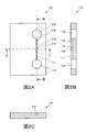
- 2A is a plan view of the first substrate
- FIG. 2B is a cross-sectional view taken along the line BB shown in FIG. 2A
- FIG. 2C is a cross-sectional view taken along the line CC shown in FIG. 2A.
- 3A is a plan view of the second substrate
- FIG. 3B is a cross-sectional view taken along the line BB shown in FIG. 3A
- FIG. 3C is a cross-sectional view taken along the line CC shown in FIG. 3A. is there. 4A is a plan view of the resin film, FIG. 4B is a cross-sectional view taken along the line BB shown in FIG. 4A, and FIG. 4C is a cross-sectional view taken along the line CC shown in FIG. 4A.
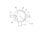
- 4 is a partially enlarged plan view of the microchannel chip according to Embodiment 1.
- FIG. 4 is a partially enlarged plan view of the microchannel chip according to Embodiment 1.
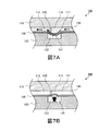
- FIG. 7A and 7B are partially enlarged cross-sectional views of the microchannel chip for explaining the usage mode of the microchannel chip of the first embodiment.
- FIG. 6 is a partially enlarged plan view showing another example of the microchannel chip according to the first embodiment.
- 6 is a plan view of a microchannel chip according to a second embodiment.
- FIG. 10A is a plan view of the first substrate
- FIG. 10B is a plan view of the second substrate
- FIG. 10C is a plan view of the resin film.
- 6 is a partially enlarged plan view of a microchannel chip according to a second embodiment.
- FIG. 12A and 12B are partially enlarged cross-sectional views of the microchannel chip for explaining a usage mode of the microchannel chip of the second embodiment.
- 6 is a partially enlarged plan view showing another example of the microchannel chip of Embodiment 2.
- FIG. 10A is a plan view of the first substrate
- FIG. 10B is a plan view of the second substrate
- FIG. 10C is a plan view of the resin film.
- 6 is a partially enlarged plan view of a microchannel chip according to a second embodiment.
- microchannel chip will be described as a representative example of the fluid handling device of the present invention.
- FIG. 1 is a diagram illustrating a configuration of the microchannel chip 100 according to the first embodiment.
- 1A is a plan view of the microchannel chip 100
- FIG. 1B is a cross-sectional view taken along line BB shown in FIG. 1A
- FIG. 1C is a cross-sectional view taken along line CC shown in FIG. 1A. It is.
- the microchannel chip 100 includes a first substrate 110, a second substrate 120, and a resin disposed between the first substrate 110 and the second substrate 120.
- Film 130 In the first substrate 110, a flow path for flowing a fluid such as a reagent or a liquid sample is formed.
- the resin film 130 functions as a diaphragm (valve element) of a microvalve that controls the flow of fluid flowing in the first flow path.
- the second substrate 120 is formed with a pressure chamber for controlling the operation of the diaphragm.
- the first substrate 110 and the second substrate 120 are integrated via a resin film 130.
- FIG. 2 is a diagram illustrating a configuration of the first substrate 110.
- 2A is a plan view of the first substrate 110
- FIG. 2B is a cross-sectional view taken along line BB shown in FIG. 2A
- FIG. 2C is a cross-sectional view taken along line CC shown in FIG. 2A. It is.
- the first substrate 110 is a transparent, substantially rectangular resin substrate.
- the thickness of the first substrate 110 is not particularly limited, but is, for example, 1 mm to 10 mm.
- the type of resin that constitutes the first substrate 110 is not particularly limited, and may be appropriately selected from known resins. Examples of the resin constituting the first substrate 110 include polyethylene terephthalate, polycarbonate, polymethyl methacrylate, vinyl chloride, polypropylene, polyether, polyethylene, and the like.
- the first substrate 110 includes a first flow path 111, a second flow path 112, a first fluid introduction port 113, a valve body facing area 114, a partition wall 115, and A fluid outlet 116 is formed.
- the first flow path 111, the valve element facing region 114, and the second flow path 112 function as one flow path, and the fluid introduced from the first fluid introduction port 113 is a fluid It can flow to the outlet 116.
- the first flow path 111 and the second flow path 112 are flow paths through which a fluid (for example, a reagent or a liquid sample) introduced from the first fluid introduction port 113 flows.
- the first flow path 111 and the second flow path 112 are grooves formed in the first substrate 110. The openings of these grooves are blocked by the resin film 130 (see FIG. 1B).
- the cross-sectional areas and cross-sectional shapes of the first flow path 111 and the second flow path 112 are not particularly limited.
- the first flow path 111 and the second flow path 112 are flow paths through which fluid can move by capillary action.
- the cross-sectional shapes of the first flow path 111 and the second flow path 112 are, for example, substantially rectangular with one side having a length (width and depth) of about several tens of ⁇ m.
- the “cross section of the flow path” means a cross section of the flow path perpendicular to the direction in which the fluid flows.
- the first fluid inlet 113 and the fluid outlet 116 are through holes formed in the first substrate 110.
- the first fluid inlet 113 is formed at the first end (upstream end) of the first flow path 111.
- the fluid outlet 116 is formed at the second end (downstream end) of the second flow path 112. One opening of these through holes is closed by the resin film 130 (see FIG. 1B).
- the shapes of the first fluid inlet 113 and the fluid outlet 116 are not particularly limited, but are, for example, substantially cylindrical.
- the diameters of the first fluid inlet 113 and the fluid outlet 116 are not particularly limited, but are about 2 mm, for example.
- the valve element facing region 114 is a recess formed in the first substrate 110.
- the valve element facing region 114 is formed at the second end (downstream end) of the first flow path 111.
- the opening of the recess faces the resin film 130 (diaphragm portion 131) (see FIG. 1B).
- the shape of the opening on the resin film 130 side of the valve element facing region 114 is substantially circular (see FIGS. 2A and 5).
- the shape of the valve element facing region 114 is not particularly limited as long as the shape of the opening is substantially circular, but is, for example, a cylindrical shape.
- region 114 is not specifically limited, For example, it is about 0.5 mm.
- the partition wall 115 is a wall formed between the first channel 111 and the first end (upstream end) of the second channel 112. As will be described later, the partition wall 115 functions as a valve seat for the microvalve.
- FIG. 3 is a diagram illustrating a configuration of the second substrate 120.
- 3A is a plan view of the second substrate 120
- FIG. 3B is a cross-sectional view taken along line BB shown in FIG. 3A
- FIG. 3C is a cross-sectional view taken along line CC shown in FIG. 3A. It is.
- the second substrate 120 is a transparent, substantially rectangular resin substrate.
- the thickness of the second substrate 120 is not particularly limited, but is, for example, 1 mm to 10 mm.
- the kind of resin that constitutes the second substrate 120 is not particularly limited, and may be appropriately selected from known resins.
- An example of the resin that constitutes the second substrate 120 is the same as the example of the resin that constitutes the first substrate 110.
- the second substrate 120 is provided with a third flow path 121, a second fluid inlet 122, and a pressure chamber 123.
- the third channel 121 is a channel through which a fluid (for example, air) introduced from the second fluid inlet 122 flows.
- the third channel 121 is a groove formed in the second substrate 120. The opening of the groove is closed by the resin film 130 (see FIG. 1C).
- the cross-sectional area and the cross-sectional shape of the third channel 121 are not particularly limited.
- the cross-sectional shape of the third flow path 121 is a substantially rectangular shape having a side length (width and depth) of about several tens of micrometers, for example.
- the second fluid introduction port 122 is a through hole formed in the second substrate 120.
- the second fluid introduction port 122 is formed at the first end (upstream end) of the third flow path 121.
- One opening of the through hole is closed by the resin film 130 (see FIG. 1C).
- the shape of the 2nd fluid introduction port 122 is not specifically limited, For example, it is a substantially cylindrical shape.
- the diameter of the 2nd fluid introduction port 122 is not specifically limited, For example, it is about 2 mm.
- the pressure chamber 123 is a recess formed in the second substrate 120.
- the pressure chamber 123 is formed at the second end (downstream end) of the third flow path 121.
- the opening of the recess is closed by the resin film 130 (see FIG. 1C).
- the shape of the opening on the resin film 130 side of the pressure chamber 123 is not particularly limited as long as it is the same size as or larger than the diaphragm 131 of the resin film 130, and is substantially circular, for example (see FIGS. 3A and 5).
- the shape of the pressure chamber 123 is not specifically limited, For example, it is a column shape.
- the diameter of the opening part of the pressure chamber 123 is not specifically limited, For example, it is about 1 mm.
- FIG. 4 is a diagram illustrating the configuration of the resin film 130.
- 4A is a plan view of the resin film 130
- FIG. 4B is a cross-sectional view taken along the line BB shown in FIG. 4A
- FIG. 4C is a cross-sectional view taken along the line CC shown in FIG. 4A. .
- the resin film 130 is a transparent substantially rectangular resin film.
- the resin film 130 functions as a valve body (diaphragm) of a microvalve having a diaphragm structure.
- the first surface of the resin film 130 is bonded to the surface of the first substrate 110 where the first flow path 111 and the like are formed. Further, the second surface of the resin film 130 is bonded to the surface of the second substrate 120 on which the third flow path 121 and the like are formed (see FIGS. 1A to 1C). As described above, the resin film 130 includes the first flow path 111, the second flow path 112, the opening of the first fluid inlet 113 and the fluid outlet 116 formed in the first substrate 110, and the first flow path. The third flow path 121, the second fluid inlet 122 and the pressure chamber 123 formed in the second substrate 120 are closed.
- the kind of resin constituting the resin film 130 is not particularly limited as long as the resin film 130 can function as a valve body (diaphragm), and can be appropriately selected from known resins.
- An example of the resin constituting the resin film 130 is the same as the example of the resin constituting the first substrate 110.
- the resin constituting the resin film 130 is a resin constituting the first substrate 110 and the second substrate 120. Are preferably the same.
- the thickness of the resin film 130 is not particularly limited as long as the resin film 130 can function as a valve body (diaphragm), and can be appropriately set according to the type (rigidity) of the resin.
- the thickness of the resin film 130 is about 20 ⁇ m.
- the resin film 130 includes a substantially spherical crown-shaped diaphragm portion 131.
- the valve element facing region 114 of the first substrate 110, the partition 115, the first end (upstream end) of the second flow path 112, and the second substrate 120 The pressure chamber 123 faces each other with the resin film 130 interposed therebetween.
- the portion is a diaphragm portion 131.
- Diaphragm portion 131 has a substantially spherical crown shape and is not bonded to first substrate 110 and second substrate 120.
- the diaphragm 131 is deformed so as to be convex toward the pressure chamber 123. For this reason, when the pressure in the pressure chamber 123 is not increased, the diaphragm portion 131 does not contact the partition 115 of the first substrate 110.
- the height of the diaphragm portion 131 in the normal state is not particularly limited as long as the fluid can flow through the gap formed between the diaphragm portion 131 and the partition wall 115. For example, the height of the diaphragm 131 is about several tens of ⁇ m.
- FIG. 5 is a partially enlarged plan view of the microchannel chip 100.
- the components formed on the first substrate 110 are indicated by solid lines
- the components formed on the second substrate 120 are indicated by broken lines
- the components formed on the resin film 130 are indicated by dashed lines. ing.
- the shape of the opening on the resin film 130 side of the valve element facing region 114 formed in the first substrate 110 is substantially circular.
- the shape of the diaphragm part 131 of the resin film 130 is substantially spherical.
- the diaphragm 131 faces not only the valve element facing region 114 but also the partition 115 and the first end portion (upstream end portion) of the second flow path 112, and therefore the substantially circular shape of the valve element facing region 114. Larger than the opening.
- the diaphragm 131 is the same size as or smaller than the opening of the pressure chamber 123.
- the center C1 of the substantially circular opening of the valve element facing region 114 coincides with the center C2 of the outer edge of the substantially spherical crown-shaped diaphragm 131. . That is, the edge of the opening of the valve element facing region 114 and the outer edge of the diaphragm 131 of the resin film 130 are concentric circles.
- the distance L from the center C2 of the diaphragm 131 to the partition wall 115 is a constant distance (the same distance as the radius of the valve element facing region 114).
- the opening portions of the diaphragm portion 131 and the pressure chamber 123 are substantially the same.
- the present invention is not limited to this. If the diaphragm portion 131 is located in the opening of the pressure chamber 123 and is formed so as to function as a diaphragm for opening and closing the communication portion between the first flow path 111 and the second flow path 112, the diaphragm
- the size of the part 131 is not particularly limited. That is, the size of the diaphragm 131 may be the same as or smaller than the opening of the pressure chamber 123.
- the microchannel chip 100 of the present embodiment includes, for example, a first substrate 110 shown in FIGS. 2A to 2C, a second substrate 120 shown in FIGS. 3A to 3C, and FIGS. 4A to 4C. It can be manufactured by bonding the resin film 130 (or flat resin film 130) shown. For example, the resin film 130 is bonded to the first substrate 110 and the second substrate 120 by adjusting various conditions and thermocompression bonding.
- FIG. 7A and 7B are partially enlarged cross-sectional views of the microchannel chip 100 for explaining the usage mode of the microchannel chip 100 (corresponding to FIG. 1B).
- the liquid 140 is introduced into the first flow path 111 by providing a liquid 140 such as a reagent or a liquid sample to the first fluid introduction port 113.
- a liquid 140 such as a reagent or a liquid sample
- the pressure in the pressure chamber 123 is not increased, and a gap is formed between the resin film 130 (diaphragm portion 131) and the partition 115 (valve open state).
- the liquid 140 travels through the first flow path 111, the partition wall 115 and the resin film 130 (diaphragm portion 131), and the second flow path 112 by capillary action or external pressure, and reaches the fluid outlet 116.
- the fluid (first fluid) introduced from the first fluid introduction port 113 does not have to be a liquid but may be a gas.
- the shape of the diaphragm 131 is substantially circular, so that the height of each point of the diaphragm 131 changes concentrically. That is, if the distance from the center of the diaphragm 131 is the same, the height is also the same.
- the distance L from the center of the diaphragm 131 to the partition wall 115 is a fixed distance (the same distance as the radius of the valve element facing region 114) ( (See FIG. 6).
- the diaphragm part 131 has a convex shape toward the valve element facing region 114, the diaphragm part 131 uniformly contacts the partition wall 115.
- the flow of the liquid 140 in the first channel 111 can be reliably stopped without excessively increasing the pressure in the pressure chamber 123.
- the microchannel chip 100 adjusts the pressure of the fluid (second fluid) in the pressure chamber 123 to adjust the fluid flowing from the first channel 111 to the second channel 112 (first 1 fluid) can be easily controlled. Moreover, since the microchannel chip 100 of this Embodiment can be manufactured using resin instead of an elastomer, manufacturing cost can be suppressed. Thus, the microchannel chip 100 of the present embodiment is inexpensive in manufacturing cost and can easily control the flow of fluid in the channel.
- microchannel chip 100 in which one microvalve structure including the valve element facing region 114, the partition wall 115, and the pressure chamber 123 is formed has been described.
- the microvalve in the microchannel chip 100 is described.
- the number of structures is not limited to this.
- a plurality of microvalve structures may be formed in one microchannel chip 100.
- FIG. 9 is a plan view showing the configuration of the microchannel chip 200 of the second embodiment.
- Microchannel chip 200 is arranged between first substrate 210, second substrate 120, first substrate 210, and second substrate 120, similarly to microchannel chip 100 of the first embodiment.
- Resin film 130 (see FIG. 12).
- FIG. 10A is a plan view of the first substrate 210
- FIG. 10B is a plan view of the second substrate 120
- FIG. 10C is a plan view of the resin film 130. Similar to the microchannel chip 100 of the first embodiment, the first substrate 210 and the second substrate 120 are integrated via a resin film 130 (see FIG. 12).
- the shape of the valve element facing region 214 and the partition wall 215 of the first substrate 210 is different from that of the microchannel chip 100 of the first embodiment. Therefore, in this embodiment mode, only the first substrate 210 will be described.
- symbol is attached
- the first substrate 210 includes a first channel 111, a second channel 112, a first fluid inlet 113, a valve body facing region 214, a partition wall 215, and a fluid outlet. 116 is formed.
- the first flow path 111, the valve element facing region 214, and the second flow path 112 function as one flow path, and the fluid introduced from the first fluid introduction port 113 is a fluid It can flow to the outlet 116.
- the valve element facing region 214 is a recess formed in the first substrate 210.
- the valve element facing region 214 is formed at the second end (downstream end) of the first flow path 111.
- the opening of the recess faces the resin film 130 (diaphragm portion 131) (see FIG. 12).
- the shape of the opening on the resin film 130 side of the valve element facing region 214 is substantially arcuate (see FIG. 10A).
- the “bow shape” refers to a shape formed when a circle is divided into two parts by one string.
- the arcuate shape includes one arc and one string connecting both ends of the arc.
- the shape of the valve element facing region 214 is not particularly limited as long as the shape of the opening is substantially arcuate, but is, for example, an arcuate column.
- the partition wall 215 is a wall formed between the valve element facing region 214 (bowed chord portion) and the first end (upstream end) of the second flow path 112.
- the partition wall 215 functions as a valve seat for the microvalve.
- FIG. 11 is a partially enlarged plan view of the microchannel chip 200.
- the components formed on the first substrate 210 are indicated by solid lines
- the components formed on the second substrate 120 are indicated by broken lines
- the components formed on the resin film 130 are indicated by dashed lines. ing.
- the shape of the opening on the resin film 130 side of the valve element facing region 214 formed in the first substrate 210 is substantially arcuate.
- the shape of the diaphragm part 131 of the resin film 130 is substantially spherical.
- the center C1 of the arc included in the edge of the substantially arcuate opening of the valve element facing region 214 is the outer edge of the substantially spherical crown diaphragm portion 131. Coincides with the center C2.
- the radius of the outer edge of the diaphragm 131 is smaller than the radius of the arc of the valve element facing region 214 (the distance between the center C1 and the arc). By doing so, as shown in FIG. 11, the distance from the edge of the opening (arc portion) of the valve element facing region 214 to the outer edge of the diaphragm 131 is constant.
- the radius of the outer edge of the diaphragm section 131 is the radius of the arc of the valve element facing area 214 ( It may be equal to or slightly larger than the distance between the center C1 and the arc.
- the resin film 130 between the edge (arc portion) of the opening of the valve element facing region 214 and the outer edge of the diaphragm 131 has a flat plate shape (see FIG. 12).
- the shape of the opening of the valve element facing region 214 is substantially arcuate. Not only the region 214 but also the partition 215 and the first end (upstream end) of the second flow path 112 can be opposed to each other.
- the first substrate 210 shown in FIG. 10A, the second substrate 120 shown in FIG. 10B, and the resin film 130 shown in FIG. 10C are joined.
- the resin film 130 is bonded to the first substrate 210 and the second substrate 120 by adjusting various conditions and thermocompression bonding.
- FIG. 12A and 12B are partially enlarged cross-sectional views of the microchannel chip 200 for explaining the usage mode of the microchannel chip 200.
- FIG. 12A and 12B are partially enlarged cross-sectional views of the microchannel chip 200 for explaining the usage mode of the microchannel chip 200.
- the liquid 140 is introduced into the first flow path 111 by providing a liquid 140 such as a reagent or a liquid sample to the first fluid introduction port 113.
- a liquid 140 such as a reagent or a liquid sample
- the pressure in the pressure chamber 123 is not increased, and a gap is formed between the resin film 130 (diaphragm portion 131) and the partition wall 215 (valve open state).
- the liquid 140 travels through the first flow path 111, the partition wall 215 and the resin film 130 (diaphragm portion 131) and the second flow path 112 by capillary action or external pressure, and reaches the fluid outlet 116.
- the fluid (first fluid) introduced from the first fluid introduction port 113 does not have to be a liquid but may be a gas.
- the radius of the outer edge of the diaphragm 131 is smaller than the radius of the arc of the valve element facing region 214, a gap is not easily formed between the diaphragm 131 and the partition 215 ( Compare FIG. 7B and FIG. 12B). Therefore, when the diaphragm 131 has a convex shape toward the valve element facing region 214, the diaphragm 131 comes into uniform contact with the partition wall 215. As a result, in the microchannel chip 200 of the present embodiment, the flow of the liquid 140 in the first channel 111 can be reliably stopped without excessively increasing the pressure in the pressure chamber 123.
- the microchannel chip 200 of the present embodiment has the effect that bubbles are less likely to enter between the diaphragm portion 131 and the partition wall 215 and is easier to handle.
- two or more ridges or ridges 214 a and 214 b extending in the direction perpendicular to the resin film 130 may be formed on the side wall constituting the valve element facing region 214.
- the two or more ridges or ridges 214 a and 214 b are preferably arranged symmetrically with respect to the opening of the first flow path 111. By doing so, it is possible to preferentially flow the liquid 140 passing through the center portion in the valve element facing region 214, and bubbles are less likely to enter between the diaphragm portion 131 and the partition wall 215.
- the fluid handling device of the present invention is useful as, for example, a microchip or a microchannel chip used in the scientific field or the medical field.
Landscapes
- Chemical & Material Sciences (AREA)
- Engineering & Computer Science (AREA)
- General Engineering & Computer Science (AREA)
- Health & Medical Sciences (AREA)
- Dispersion Chemistry (AREA)
- General Health & Medical Sciences (AREA)
- Analytical Chemistry (AREA)
- Chemical Kinetics & Catalysis (AREA)
- Mechanical Engineering (AREA)
- Clinical Laboratory Science (AREA)
- Hematology (AREA)
- Life Sciences & Earth Sciences (AREA)
- Physics & Mathematics (AREA)
- Immunology (AREA)
- Hydrology & Water Resources (AREA)
- Biochemistry (AREA)
- General Physics & Mathematics (AREA)
- Pathology (AREA)
- Organic Chemistry (AREA)
- Fluid Mechanics (AREA)
- Micromachines (AREA)
- Automatic Analysis And Handling Materials Therefor (AREA)
Abstract
流体取扱装置(100)は、第1の基板(210)と、第2の基板(120)と、第1の基板(210)および第2の基板(120)の間に配置された樹脂フィルム(130)とを有する。第1の基板(210)には、第1の流路(111)と、第1の流路(111)の端部に形成された弁体対向領域(214)と、第2の流路(112)と、弁体対向領域(214)と第2の流路(112)の端部との間に位置する隔壁(215)とが形成されている。第2の基板(120)には、圧力室(123)が形成されている。弁体対向領域(214)および隔壁(215)と、圧力室(123)とは、樹脂フィルム(130)のダイヤフラム部(131)を挟んで互いに対向している。
Description
本発明は、液体試料の分析や処理などに用いられる流体取扱装置および流体取扱方法に関する。
近年、タンパク質や核酸などの微量な物質の分析を高精度かつ高速に行うために、マイクロ流路チップが使用されている。マイクロ流路チップは、試薬および試料の量が少なくてよいという利点を有しており、臨床検査や食物検査、環境検査などの様々な用途での使用が期待されている。
マイクロ流路チップを用いた処理を自動化するために、マイクロ流路チップ内にバルブ構造を設けることが提案されている(例えば、特許文献1参照)。
特許文献1には、流路の側壁の形状を変化させることで流路を開閉するダイヤフラム弁構造のマイクロバルブを有するマイクロ流路チップが開示されている。このマイクロ流路チップでは、第1の流路の近傍に第2の流路が形成されている。第2の流路内の流体の圧力が高まると、第1の流路および第2の流路の間に位置する第1の流路の壁(ダイヤフラム)が第1の流路を塞ぐように変形する。したがって、第2の流路内の流体の圧力を調整することで、第1の流路内の流体の流れを制御することができる。
しかしながら、特許文献1に記載のマイクロ流路チップには、製造コストが高いという問題がある。すなわち、特許文献1に記載の技術では、第1の流路の壁(ダイヤフラム)に弾性を持たせるために、マイクロ流路チップ全体を高価なエラストマー(例えば、ポリジメチルシロキサン(PDMS))で作製している。このため、特許文献1に記載の技術では、マイクロ流路チップを安価に製造することが困難である。
製造コストを抑制する手段としては、樹脂を用いてマイクロ流路チップを作製することが考えられる。しかしながら、ある程度の厚みを有する樹脂フィルムを用いてダイヤフラムを作製した場合、樹脂はエラストマーに比べて剛性が高いため、樹脂フィルム(ダイヤフラム)により流路を完全に塞ぐことは困難である。すなわち、樹脂フィルム(ダイヤフラム)の一部が流路に接触してしまった後、ダイヤフラムの残部を流路に接触させるためには、非常に大きな圧力をかけなければならないのである。
本発明の目的は、製造コストが安価であり、かつ流路内の流体の流れを容易に制御することができる流体取扱装置、および前記流体取扱装置を用いた流体取扱方法を提供することである。
本発明の流体取扱装置は、第1の流路と、前記第1の流路の一方の端部に形成され、かつ略弓形の開口部を有する弁体対向領域と、第2の流路と、前記弁体対向領域および前記第2の流路の一方の端部の間に形成された隔壁とを含む第1の基板と、第3の流路と、前記第3の流路の一方の端部に形成され、かつ開口部を有する圧力室とを含む第2の基板と、前記第1の基板と前記第2の基板との間に配置され、略球冠状のダイヤフラム部を含む樹脂フィルムと、を有し、前記第1の基板および前記第2の基板は、前記樹脂フィルムを介して一体化されており、前記ダイヤフラム部は、前記弁体対向領域の開口部、前記第2の流路の一方の端部および前記隔壁と、前記圧力室の開口部との間に位置しており、平面視したときに、前記弁体対向領域の開口部の縁に含まれる円弧の中心および前記ダイヤフラム部の外縁の中心は一致し、前記圧力室内の圧力により前記ダイヤフラム部が前記隔壁に接触することで、前記弁体対向領域から前記隔壁と前記ダイヤフラム部との間を通って前記第2の流路へ向かう流体の流れが止まる、構成を採る。
本発明の流体取扱装置は、第1の流路と、前記第1の流路の一方の端部に形成され、かつ略円形の開口部を有する弁体対向領域と、第2の流路と、前記弁体対向領域および前記第2の流路の一方の端部の間に形成された隔壁とを含む第1の基板と、第3の流路と、前記第3の流路の一方の端部に形成され、かつ開口部を有する圧力室とを含む第2の基板と、前記第1の基板と前記第2の基板との間に配置され、略球冠状のダイヤフラム部を含む樹脂フィルムと、を有し、前記第1の基板および前記第2の基板は、前記樹脂フィルムを介して一体化されており、前記ダイヤフラム部は、前記弁体対向領域の開口部、前記第2の流路の一方の端部および前記隔壁と、前記圧力室の開口部との間に位置しており、平面視したときに、前記ダイヤフラム部は、前記弁体対向領域の開口部よりも大きく、かつ前記弁体対向領域の開口部の縁および前記樹脂フィルムの前記ダイヤフラム部の外縁は、同心円であり、前記圧力室内の圧力により前記ダイヤフラム部が前記隔壁に接触することで、前記弁体対向領域から前記隔壁と前記ダイヤフラム部との間を通って前記第2の流路へ向かう流体の流れが止まる、構成を採る。
本発明の流体取扱方法は、上記の流体取扱装置を使用して流体を取り扱う方法であって、前記第1の流路に第1の流体を導入して、前記第1の流路から、前記隔壁および前記ダイヤフラム部の間を通して前記第2の流路に前記第1の流体を移動させるステップと、前記第3の流路を通して前記圧力室に第2の流体を導入することで、前記圧力室内の前記第2の流体の圧力により前記ダイヤフラム部を前記隔壁に接触させて、前記第1の流体の流れを止めるステップと、を含む。
本発明によれば、製造コストが安価であり、かつ流路内の流体の流れを容易に制御することができる流体取扱装置、および前記流体取扱装置を用いた流体取扱方法を提供することができる。
以下、本発明の実施の形態について、図面を参照して詳細に説明する。以下の説明では、本発明の流体取扱装置の代表例として、マイクロ流路チップについて説明する。
<実施の形態1>
[マイクロ流路チップの構成]
図1は、実施の形態1のマイクロ流路チップ100の構成を示す図である。図1Aは、マイクロ流路チップ100の平面図であり、図1Bは、図1Aに示されるB-B線の断面図であり、図1Cは、図1Aに示されるC-C線の断面図である。
[マイクロ流路チップの構成]
図1は、実施の形態1のマイクロ流路チップ100の構成を示す図である。図1Aは、マイクロ流路チップ100の平面図であり、図1Bは、図1Aに示されるB-B線の断面図であり、図1Cは、図1Aに示されるC-C線の断面図である。
図1A~図1Cに示されるように、マイクロ流路チップ100は、第1の基板110と、第2の基板120と、第1の基板110および第2の基板120の間に配置された樹脂フィルム130とを有する。第1の基板110には、試薬や液体試料などの流体を流すための流路が形成されている。一方、樹脂フィルム130は、第1の流路内を流れる流体の流れを制御するマイクロバルブのダイヤフラム(弁体)として機能する。第2の基板120には、ダイヤフラムの動作を制御するための圧力室が形成されている。第1の基板110および第2の基板120は、樹脂フィルム130を介して一体化されている。
以下、マイクロ流路チップ100の各構成要素について説明する。
(第1の基板)
図2は、第1の基板110の構成を示す図である。図2Aは、第1の基板110の平面図であり、図2Bは、図2Aに示されるB-B線の断面図であり、図2Cは、図2Aに示されるC-C線の断面図である。
図2は、第1の基板110の構成を示す図である。図2Aは、第1の基板110の平面図であり、図2Bは、図2Aに示されるB-B線の断面図であり、図2Cは、図2Aに示されるC-C線の断面図である。
第1の基板110は、透明な略矩形の樹脂基板である。第1の基板110の厚さは、特に限定されないが、例えば1mm~10mmである。第1の基板110を構成する樹脂の種類は、特に限定されず、公知の樹脂から適宜選択されうる。第1の基板110を構成する樹脂の例には、ポリエチレンテレフタレート、ポリカーボネート、ポリメタクリル酸メチル、塩化ビニール、ポリプロピレン、ポリエーテル、ポリエチレンなどが含まれる。
図2A~図2Cに示されるように、第1の基板110には、第1の流路111、第2の流路112、第1の流体導入口113、弁体対向領域114、隔壁115および流体取出口116が形成されている。マイクロバルブの開放時には、第1の流路111、弁体対向領域114および第2の流路112は、一つの流路として機能し、第1の流体導入口113から導入された流体は、流体取出口116まで流れることができる。
第1の流路111および第2の流路112は、第1の流体導入口113から導入された流体(例えば、試薬や液体試料など)が流れる流路である。第1の流路111および第2の流路112は、第1の基板110に形成された溝である。これらの溝の開口部は、樹脂フィルム130により塞がれる(図1B参照)。第1の流路111および第2の流路112の断面積および断面形状は、特に限定されない。たとえば、第1の流路111および第2の流路112は、毛管現象により流体が移動可能な流路である。この場合、第1の流路111および第2の流路112の断面形状は、例えば一辺の長さ(幅および深さ)が数十μm程度の略矩形である。なお、本明細書において、「流路の断面」とは、流体が流れる方向に直交する流路の断面を意味する。
第1の流体導入口113および流体取出口116は、第1の基板110に形成された貫通孔である。第1の流体導入口113は、第1の流路111の第1の端部(上流側の端部)に形成されている。また、流体取出口116は、第2の流路112の第2の端部(下流側の端部)に形成されている。これらの貫通孔の一方の開口部は、樹脂フィルム130により塞がれる(図1B参照)。第1の流体導入口113および流体取出口116の形状は、特に限定されないが、例えば略円柱状である。第1の流体導入口113および流体取出口116の直径は、特に限定されないが、例えば2mm程度である。
弁体対向領域114は、第1の基板110に形成された凹部である。弁体対向領域114は、第1の流路111の第2の端部(下流側の端部)に形成されている。凹部の開口部は、樹脂フィルム130(ダイヤフラム部131)と対向している(図1B参照)。弁体対向領域114の樹脂フィルム130側の開口部の形状は、略円形である(図2Aおよび図5参照)。弁体対向領域114の形状は、開口部の形状が略円形であれば特に限定されないが、例えば円柱状である。弁体対向領域114の開口部の直径は、特に限定されないが、例えば0.5mm程度である。
隔壁115は、第1の流路111と第2の流路112の第1の端部(上流側の端部)との間に形成された壁である。後述するように、隔壁115は、マイクロバルブの弁座として機能する。
(第2の基板)
図3は、第2の基板120の構成を示す図である。図3Aは、第2の基板120の平面図であり、図3Bは、図3Aに示されるB-B線の断面図であり、図3Cは、図3Aに示されるC-C線の断面図である。
図3は、第2の基板120の構成を示す図である。図3Aは、第2の基板120の平面図であり、図3Bは、図3Aに示されるB-B線の断面図であり、図3Cは、図3Aに示されるC-C線の断面図である。
第2の基板120は、透明な略矩形の樹脂基板である。第2の基板120の厚さは、特に限定されないが、例えば1mm~10mmである。第2の基板120を構成する樹脂の種類は、特に限定されず、公知の樹脂から適宜選択されうる。第2の基板120を構成する樹脂の例は、第1の基板110を構成する樹脂の例と同じである。
図3A~図3Cに示されるように、第2の基板120には、第3の流路121、第2の流体導入口122および圧力室123が形成されている。
第3の流路121は、第2の流体導入口122から導入された流体(例えば、空気など)が流れる流路である。第3の流路121は、第2の基板120に形成された溝である。溝の開口部は、樹脂フィルム130により塞がれる(図1C参照)。第3の流路121の断面積および断面形状は、特に限定されない。たとえば、第3の流路121の断面形状は、例えば一辺の長さ(幅および深さ)が数十μm程度の略矩形である。
第2の流体導入口122は、第2の基板120に形成された貫通孔である。第2の流体導入口122は、第3の流路121の第1の端部(上流側の端部)に形成されている。貫通孔の一方の開口部は、樹脂フィルム130により塞がれる(図1C参照)。第2の流体導入口122の形状は、特に限定されないが、例えば略円柱状である。第2の流体導入口122の直径は、特に限定されないが、例えば2mm程度である。
圧力室123は、第2の基板120に形成された凹部である。圧力室123は、第3の流路121の第2の端部(下流側の端部)に形成されている。凹部の開口部は、樹脂フィルム130により塞がれる(図1C参照)。圧力室123の樹脂フィルム130側の開口部の形状は、樹脂フィルム130のダイヤフラム部131と同じ大きさか、またはそれより大きければ特に限定されず、例えば略円形である(図3Aおよび図5参照)。圧力室123の形状は、特に限定されないが、例えば円柱状である。圧力室123の開口部の直径は、特に限定されないが、例えば1mm程度である。
(樹脂フィルム)
図4は、樹脂フィルム130の構成を示す図である。図4Aは、樹脂フィルム130の平面図であり、図4Bは、図4Aに示されるB-B線の断面図であり、図4Cは、図4Aに示されるC-C線の断面図である。
図4は、樹脂フィルム130の構成を示す図である。図4Aは、樹脂フィルム130の平面図であり、図4Bは、図4Aに示されるB-B線の断面図であり、図4Cは、図4Aに示されるC-C線の断面図である。
樹脂フィルム130は、透明な略矩形の樹脂フィルムである。樹脂フィルム130は、ダイヤフラム構造のマイクロバルブの弁体(ダイヤフラム)として機能する。
樹脂フィルム130の第1の面は、第1の基板110の第1の流路111などが形成された面に接合されている。また、樹脂フィルム130の第2の面は、第2の基板120の第3の流路121などが形成された面に接合されている(図1A~図1C参照)。前述の通り、樹脂フィルム130は、第1の基板110に形成された第1の流路111、第2の流路112、第1の流体導入口113および流体取出口116の開口部、ならびに第2の基板120に形成された第3の流路121、第2の流体導入口122および圧力室123の開口部を閉塞している。
樹脂フィルム130を構成する樹脂の種類は、樹脂フィルム130が弁体(ダイヤフラム)として機能できれば特に限定されず、公知の樹脂から適宜選択されうる。樹脂フィルム130を構成する樹脂の例は、第1の基板110を構成する樹脂の例と同じである。樹脂フィルム130と第1の基板110および第2の基板120との密着性を向上させる観点からは、樹脂フィルム130を構成する樹脂は、第1の基板110および第2の基板120を構成する樹脂と同一であることが好ましい。
樹脂フィルム130の厚さは、樹脂フィルム130が弁体(ダイヤフラム)として機能できれば特に限定されず、樹脂の種類(剛性)に応じて適宜設定されうる。たとえば、樹脂フィルム130の厚さは、20μm程度である。
図4A~図4Cに示されるように、樹脂フィルム130は、略球冠状のダイヤフラム部131を含む。図1Bに示されるように、第1の基板110の弁体対向領域114、隔壁115および第2の流路112の第1の端部(上流側の端部)と、第2の基板120の圧力室123とは、樹脂フィルム130を挟んで互いに対向している。樹脂フィルム130のうち、弁体対向領域114の開口部、隔壁115および第2の流路112の第1の端部(上流側の端部)と圧力室123の開口部との間に位置する部分がダイヤフラム部131である。ダイヤフラム部131は、略球冠状であり、第1の基板110および第2の基板120に接合されていない。
図4Bおよび図4Cに示されるように、ダイヤフラム部131は、圧力室123に向かって凸形状となるように変形している。このため、圧力室123内の圧力が高まっていない場合は、ダイヤフラム部131は、第1の基板110の隔壁115とは接触しない。通常状態のダイヤフラム部131の高さは、ダイヤフラム部131と隔壁115との間に形成される隙間を流体が流れることができれば特に限定されない。たとえば、ダイヤフラム部131の高さは、数十μm程度である。
図5は、マイクロ流路チップ100の部分拡大平面図である。この図では、第1の基板110に形成された構成要素を実線で示し、第2の基板120に形成された構成要素を破線で示し、樹脂フィルム130に形成された構成要素を一点鎖線で示している。前述の通り、第1の基板110に形成された弁体対向領域114の樹脂フィルム130側の開口部の形状は、略円形である。また、樹脂フィルム130のダイヤフラム部131の形状は、略球冠状である。ダイヤフラム部131は、弁体対向領域114だけでなく、隔壁115および第2の流路112の第1の端部(上流側の端部)とも対向するため、弁体対向領域114の略円形の開口部よりも大きい。一方で、ダイヤフラム部131は、圧力室123の開口部とは同じ大きさか、それよりも小さい。
図5に示されるように、マイクロ流路チップ100を平面視した場合、弁体対向領域114の略円形の開口部の中心C1は、略球冠状のダイヤフラム部131の外縁の中心C2と一致する。すなわち、弁体対向領域114の開口部の縁および樹脂フィルム130のダイヤフラム部131の外縁は、同心円である。このようにすることで、図6に示されるように、ダイヤフラム部131の中心C2から隔壁115までの距離Lが、一定の距離(弁体対向領域114の半径と同じ距離)となる。
なお、図1、図5および図6に示される例では、ダイヤフラム部131および圧力室123の開口部の大きさがほぼ一致している態様を示しているが、本発明はこれに限定されず、ダイヤフラム部131が圧力室123の開口部内に位置し、第1の流路111と第2の流路112との連通部を開閉させるためのダイヤフラムとして機能するように形成されていれば、ダイヤフラム部131の大きさは特に限定されない。すなわち、ダイヤフラム部131の大きさは、圧力室123の開口部と同じ大きさか、それよりも小さくてもよい。
本実施の形態のマイクロ流路チップ100は、例えば、図2A~図2Cに示される第1の基板110と、図3A~図3Cに示される第2の基板120と、図4A~図4Cに示される樹脂フィルム130(または平らな樹脂フィルム130)とを接合することで製造されうる。たとえば、樹脂フィルム130は、諸条件を調整して熱圧着により第1の基板110および第2の基板120に接合される。
[マイクロ流路チップの使用方法]
次に、本実施の形態のマイクロ流路チップ100の使用方法について、図7を参照して説明する。図7Aおよび図7Bは、マイクロ流路チップ100の使用態様を説明するためのマイクロ流路チップ100の部分拡大断面図である(図1Bに対応)。
次に、本実施の形態のマイクロ流路チップ100の使用方法について、図7を参照して説明する。図7Aおよび図7Bは、マイクロ流路チップ100の使用態様を説明するためのマイクロ流路チップ100の部分拡大断面図である(図1Bに対応)。
まず、図7Aに示されるように、第1の流体導入口113に試薬や液体試料などの液体140を提供することで、第1の流路111に液体140を導入する。このとき、圧力室123内の圧力は高められておらず、樹脂フィルム130(ダイヤフラム部131)と隔壁115との間には隙間が形成されている(バルブ開放状態)。液体140は、毛管現象または外部からの圧力により第1の流路111、隔壁115と樹脂フィルム130(ダイヤフラム部131)との間、および第2の流路112を進み、流体取出口116に到達する。なお、第1の流体導入口113から導入される流体(第1の流体)は、液体である必要はなく、気体であってもよい。
次いで、図7Bに示されるように、第2の流体導入口122から第3の流路121を通して圧力室123に空気を導入する。その結果、圧力室123内の圧力が高まり、樹脂フィルム130(ダイヤフラム部131)の形状が変化する。具体的には、ダイヤフラム部131は、弁体対向領域114側に凸の形状となる。これにより、樹脂フィルム130(ダイヤフラム部131)は隔壁115に接触する(バルブ閉鎖状態)。液体140は、隔壁115と樹脂フィルム130(ダイヤフラム部131)との間を進むことができなくなり、液体140の流れは止まる。なお、第2の流体導入口122から導入される流体(第2の流体)は、空気である必要はなく、液体または空気以外の気体であってもよい。
ダイヤフラム部131が弁体対向領域114側に凸の形状となった場合、ダイヤフラム部131の形状は略円形であるため、ダイヤフラム部131の各地点の高さは、同心円状に変化する。すなわち、ダイヤフラム部131の中心からの距離が同じであれば、高さも同じである。前述の通り、本実施の形態のマイクロ流路チップ100では、ダイヤフラム部131の中心から隔壁115までの距離Lが、一定の距離(弁体対向領域114の半径と同じ距離)となっている(図6参照)。したがって、ダイヤフラム部131が弁体対向領域114側に凸の形状となった場合、ダイヤフラム部131は、隔壁115に均一に接触する。結果として、本実施の形態のマイクロ流路チップ100では、圧力室123内の圧力を過剰に高めなくても、第1の流路111内の液体140の流れを確実に止めることができる。
以上の手順により、液体140を第1の流路110から第2の流路112に流すこと、および第1の流路110から第2の流路112への液体140の流れを止めること、を任意のタイミングで行うことができる。たとえば、第1の流体導入口113内において液体140を特定の試薬と一定時間反応させた後に、第1の流体導入口113内の液体140を流体取出口116内に移動させて、流体取出口116内において液体140を別の試薬と反応させることが可能である。
[効果]
本実施の形態のマイクロ流路チップ100は、圧力室123内の流体(第2の流体)の圧力を調整することで、第1の流路111から第2の流路112に流れる流体(第1の流体)の流れを容易に制御することができる。また、本実施の形態のマイクロ流路チップ100は、エラストマーではなく樹脂を用いて製造されうるため、製造コストを抑制することができる。このように、本実施の形態のマイクロ流路チップ100は、製造コストが安価であり、かつ流路内の流体の流れを容易に制御することができる。
本実施の形態のマイクロ流路チップ100は、圧力室123内の流体(第2の流体)の圧力を調整することで、第1の流路111から第2の流路112に流れる流体(第1の流体)の流れを容易に制御することができる。また、本実施の形態のマイクロ流路チップ100は、エラストマーではなく樹脂を用いて製造されうるため、製造コストを抑制することができる。このように、本実施の形態のマイクロ流路チップ100は、製造コストが安価であり、かつ流路内の流体の流れを容易に制御することができる。
なお、これまでの説明では、弁体対向領域114、隔壁115および圧力室123を含むマイクロバルブ構造が1つ形成されたマイクロ流路チップ100について説明したが、マイクロ流路チップ100内のマイクロバルブ構造の数はこれに限定されない。たとえば、図8に示されるように、1つのマイクロ流路チップ100内に複数のマイクロバルブ構造が形成されていてもよい。
<実施の形態2>
[マイクロ流路チップの構成]
図9は、実施の形態2のマイクロ流路チップ200の構成を示す平面図である。マイクロ流路チップ200は、実施の形態1のマイクロ流路チップ100と同様に、第1の基板210と、第2の基板120と、第1の基板210および第2の基板120の間に配置された樹脂フィルム130とを有する(図12参照)。
[マイクロ流路チップの構成]
図9は、実施の形態2のマイクロ流路チップ200の構成を示す平面図である。マイクロ流路チップ200は、実施の形態1のマイクロ流路チップ100と同様に、第1の基板210と、第2の基板120と、第1の基板210および第2の基板120の間に配置された樹脂フィルム130とを有する(図12参照)。
図10Aは、第1の基板210の平面図であり、図10Bは、第2の基板120の平面図であり、図10Cは、樹脂フィルム130の平面図である。実施の形態1のマイクロ流路チップ100と同様に、第1の基板210および第2の基板120は、樹脂フィルム130を介して一体化されている(図12参照)。
実施の形態2のマイクロ流路チップ200では、第1の基板210が有する弁体対向領域214、隔壁215の形状が実施の形態1のマイクロ流路チップ100と異なる。そこで、本実施の形態では、第1の基板210についてのみ説明する。なお、実施の形態1のマイクロ流路チップ100と同一の構成要素については、同一の符号を付してその説明を省略する。
図10Aに示されるように、第1の基板210には、第1の流路111、第2の流路112、第1の流体導入口113、弁体対向領域214、隔壁215および流体取出口116が形成されている。マイクロバルブの開放時には、第1の流路111、弁体対向領域214および第2の流路112は、一つの流路として機能し、第1の流体導入口113から導入された流体は、流体取出口116まで流れることができる。
弁体対向領域214は、第1の基板210に形成された凹部である。弁体対向領域214は、第1の流路111の第2の端部(下流側の端部)に形成されている。凹部の開口部は、樹脂フィルム130(ダイヤフラム部131)と対向している(図12参照)。弁体対向領域214の樹脂フィルム130側の開口部の形状は、略弓形である(図10A参照)。ここで「弓形」とは、円を1つの弦で2つに分けたときにできる形状をいう。弓形は、1つの円弧と、前記円弧の両端を結ぶ1つの弦とを含む。弁体対向領域214の形状は、開口部の形状が略弓形であれば特に限定されないが、例えば弓形柱状である。
隔壁215は、弁体対向領域214(弓形の弦の部分)と、第2の流路112の第1の端部(上流側の端部)との間に形成された壁である。隔壁215は、マイクロバルブの弁座として機能する。
図11は、マイクロ流路チップ200の部分拡大平面図である。この図では、第1の基板210に形成された構成要素を実線で示し、第2の基板120に形成された構成要素を破線で示し、樹脂フィルム130に形成された構成要素を一点鎖線で示している。前述の通り、第1の基板210に形成された弁体対向領域214の樹脂フィルム130側の開口部の形状は、略弓形である。また、樹脂フィルム130のダイヤフラム部131の形状は、略球冠状である。
図11に示されるように、マイクロ流路チップ200を平面視した場合、弁体対向領域214の略弓形の開口部の縁に含まれる円弧の中心C1は、略球冠状のダイヤフラム部131の外縁の中心C2と一致する。また、ダイヤフラム部131の外縁の半径は、弁体対向領域214の前記円弧の半径(中心C1と円弧との距離)よりも小さい。このようにすることで、図11に示されるように、弁体対向領域214の開口部の縁(円弧の部分)からダイヤフラム部131の外縁までの距離が一定となる。なお、弁体対向領域214の開口部の縁(円弧の部分)からダイヤフラム部131の外縁までの距離が一定であれば、ダイヤフラム部131の外縁の半径が弁体対向領域214の円弧の半径(中心C1と円弧との距離)と同等かまたはわずかに大きくてもよい。弁体対向領域214の開口部の縁(円弧の部分)とダイヤフラム部131の外縁との間の樹脂フィルム130は、平板状である(図12参照)。
なお、ダイヤフラム部131の外縁の半径が弁体対向領域214の円弧の半径よりも小さい場合でも、弁体対向領域214の開口部の形状が略弓形であるため、ダイヤフラム部131は、弁体対向領域214だけでなく、隔壁215および第2の流路112の第1の端部(上流側の端部)とも対向することができる。
本実施の形態のマイクロ流路チップ200は、例えば、図10Aに示される第1の基板210と、図10Bに示される第2の基板120と、図10Cに示される樹脂フィルム130とを接合することで製造されうる。たとえば、樹脂フィルム130は、諸条件を調整して熱圧着により第1の基板210および第2の基板120に接合される。
[マイクロ流路チップの使用方法]
次に、本実施の形態のマイクロ流路チップ200の使用方法について、図12を参照して説明する。図12Aおよび図12Bは、マイクロ流路チップ200の使用態様を説明するためのマイクロ流路チップ200の部分拡大断面図である。
次に、本実施の形態のマイクロ流路チップ200の使用方法について、図12を参照して説明する。図12Aおよび図12Bは、マイクロ流路チップ200の使用態様を説明するためのマイクロ流路チップ200の部分拡大断面図である。
まず、図12Aに示されるように、第1の流体導入口113に試薬や液体試料などの液体140を提供することで、第1の流路111に液体140を導入する。このとき、圧力室123内の圧力は高められておらず、樹脂フィルム130(ダイヤフラム部131)と隔壁215との間には隙間が形成されている(バルブ開放状態)。液体140は、毛管現象または外部からの圧力により第1の流路111、隔壁215と樹脂フィルム130(ダイヤフラム部131)との間、および第2の流路112を進み、流体取出口116に到達する。なお、第1の流体導入口113から導入される流体(第1の流体)は、液体である必要はなく、気体であってもよい。
次いで、図12Bに示されるように、第2の流体導入口122から第3の流路121を通して圧力室123に空気を導入する。その結果、圧力室123内の圧力が高まり、樹脂フィルム130(ダイヤフラム部131)の形状が変化する。具体的には、ダイヤフラム部131は、弁体対向領域214側に凸の形状となる。これにより、樹脂フィルム130(ダイヤフラム部131)は隔壁215に接触する(バルブ閉鎖状態)。液体140は、隔壁215と樹脂フィルム130(ダイヤフラム部131)との間を進むことができなくなり、液体140の流れは止まる。なお、第2の流体導入口122から導入される流体(第2の流体)は、空気である必要はなく、液体または空気以外の気体であってもよい。
本実施の形態のマイクロ流路チップ200では、ダイヤフラム部131の外縁の半径が弁体対向領域214の円弧の半径よりも小さいため、ダイヤフラム部131と隔壁215との間に隙間が形成されにくい(図7Bと図12Bを比較参照)。したがって、ダイヤフラム部131が弁体対向領域214側に凸の形状となった場合、ダイヤフラム部131は、隔壁215に均一に接触する。結果として、本実施の形態のマイクロ流路チップ200では、圧力室123内の圧力を過剰に高めなくても、第1の流路111内の液体140の流れを確実に止めることができる。
以上の手順により、液体140を第1の流路110から第2の流路112に流すこと、および第1の流路110から第2の流路112への液体140の流れを止めること、を任意のタイミングで行うことができる。
[効果]
本実施の形態のマイクロ流路チップ200は、実施の形態1のマイクロ流路チップ100と同様の効果に加えて、ダイヤフラム部131と隔壁215との間に気泡が入りにくく、より扱いやすいという効果を有する。
本実施の形態のマイクロ流路チップ200は、実施の形態1のマイクロ流路チップ100と同様の効果に加えて、ダイヤフラム部131と隔壁215との間に気泡が入りにくく、より扱いやすいという効果を有する。
なお、図13に示されるように、弁体対向領域214を構成する側壁に、樹脂フィルム130に対して垂直方向に伸びる2以上の凸条または凹条214a,214bが形成されていてもよい。この場合、2以上の凸条または凹条214a,214bは、第1の流路111の開口部に対して対称に配置されていることが好ましい。このようにすることで、弁体対向領域214内において中央部を通る液体140を優先的に流すことが可能となり、ダイヤフラム部131と隔壁215との間に気泡がより入りにくくなる。
本出願は、2011年7月25日出願の特願2011-161914および2012年7月19日出願の特願2012-160407に基づく優先権を主張する。当該出願明細書および図面に記載された内容は、すべて本願明細書に援用される。
本発明の流体取扱装置は、例えば、科学分野や医学分野などにおいて使用されるマイクロチップまたはマイクロ流路チップとして有用である。
100,200 マイクロ流路チップ
110,210 第1の基板
111 第1の流路
112 第2の流路
113 第1の流体導入口
114,214 弁体対向領域
115,215 隔壁
116 流体取出口
120 第2の基板
121 第3の流路
122 第2の流体導入口
123 圧力室
130 樹脂フィルム
131 ダイヤフラム部
140 液体
214a,214b 凹条
110,210 第1の基板
111 第1の流路
112 第2の流路
113 第1の流体導入口
114,214 弁体対向領域
115,215 隔壁
116 流体取出口
120 第2の基板
121 第3の流路
122 第2の流体導入口
123 圧力室
130 樹脂フィルム
131 ダイヤフラム部
140 液体
214a,214b 凹条
Claims (5)
- 第1の流路と、前記第1の流路の一方の端部に形成され、かつ略弓形の開口部を有する弁体対向領域と、第2の流路と、前記弁体対向領域および前記第2の流路の一方の端部の間に形成された隔壁とを含む第1の基板と、
第3の流路と、前記第3の流路の一方の端部に形成され、かつ開口部を有する圧力室とを含む第2の基板と、
前記第1の基板と前記第2の基板との間に配置され、略球冠状のダイヤフラム部を含む樹脂フィルムと、を有し、
前記第1の基板および前記第2の基板は、前記樹脂フィルムを介して一体化されており、
前記ダイヤフラム部は、前記弁体対向領域の開口部、前記第2の流路の一方の端部および前記隔壁と、前記圧力室の開口部との間に位置しており、
平面視したときに、前記弁体対向領域の開口部の縁に含まれる円弧の中心および前記ダイヤフラム部の外縁の中心は一致し、
前記圧力室内の圧力により前記ダイヤフラム部が前記隔壁に接触することで、前記弁体対向領域から前記隔壁と前記ダイヤフラム部との間を通って前記第2の流路へ向かう流体の流れが止まる、
流体取扱装置。 - 前記ダイヤフラム部の外縁の半径は、前記弁体対向領域の前記円弧の半径よりも小さい、請求項1に記載の流体取扱装置。
- 第1の流路と、前記第1の流路の一方の端部に形成され、かつ略円形の開口部を有する弁体対向領域と、第2の流路と、前記弁体対向領域および前記第2の流路の一方の端部の間に形成された隔壁とを含む第1の基板と、
第3の流路と、前記第3の流路の一方の端部に形成され、かつ開口部を有する圧力室とを含む第2の基板と、
前記第1の基板と前記第2の基板との間に配置され、略球冠状のダイヤフラム部を含む樹脂フィルムと、を有し、
前記第1の基板および前記第2の基板は、前記樹脂フィルムを介して一体化されており、
前記ダイヤフラム部は、前記弁体対向領域の開口部、前記第2の流路の一方の端部および前記隔壁と、前記圧力室の開口部との間に位置しており、
平面視したときに、前記ダイヤフラム部は、前記弁体対向領域の開口部よりも大きく、かつ前記弁体対向領域の開口部の縁および前記樹脂フィルムの前記ダイヤフラム部の外縁は、同心円であり、
前記圧力室内の圧力により前記ダイヤフラム部が前記隔壁に接触することで、前記弁体対向領域から前記隔壁と前記ダイヤフラム部との間を通って前記第2の流路へ向かう流体の流れが止まる、
流体取扱装置。 - 前記弁体対向領域を構成する側壁に、前記樹脂フィルムに対して垂直方向に伸びる2以上の凸条または凹条が形成されており、
前記2以上の凸条または凹条は、前記第1の流路の開口部に対して対称に配置されている、
請求項1~3のいずれか一項に記載の流体取扱装置。 - 請求項1~4のいずれか一項に記載の流体取扱装置を使用して流体を取り扱う方法であって、
前記第1の流路に第1の流体を導入して、前記第1の流路から、前記隔壁および前記ダイヤフラム部の間を通して前記第2の流路に前記第1の流体を移動させるステップと、
前記第3の流路を通して前記圧力室に第2の流体を導入することで、前記圧力室内の前記第2の流体の圧力により前記ダイヤフラム部を前記隔壁に接触させて、前記第1の流体の流れを止めるステップと、
を含む、流体取扱方法。
Priority Applications (3)
| Application Number | Priority Date | Filing Date | Title |
|---|---|---|---|
| EP20120816989 EP2738431A4 (en) | 2011-07-25 | 2012-07-23 | FLUID TREATMENT APPARATUS AND METHOD FOR TREATING A FLUID |
| US14/234,686 US9261436B2 (en) | 2011-07-25 | 2012-07-23 | Fluid treatment device and method for treating fluid |
| US14/990,826 US9463459B2 (en) | 2011-07-25 | 2016-01-08 | Fluid handling device and method of handling fluid |
Applications Claiming Priority (4)
| Application Number | Priority Date | Filing Date | Title |
|---|---|---|---|
| JP2011-161914 | 2011-07-25 | ||
| JP2011161914 | 2011-07-25 | ||
| JP2012-160407 | 2012-07-19 | ||
| JP2012160407A JP6068850B2 (ja) | 2011-07-25 | 2012-07-19 | 流体取扱装置および流体取扱方法 |
Related Child Applications (2)
| Application Number | Title | Priority Date | Filing Date |
|---|---|---|---|
| US14/234,686 A-371-Of-International US9261436B2 (en) | 2011-07-25 | 2012-07-23 | Fluid treatment device and method for treating fluid |
| US14/990,826 Continuation US9463459B2 (en) | 2011-07-25 | 2016-01-08 | Fluid handling device and method of handling fluid |
Publications (1)
| Publication Number | Publication Date |
|---|---|
| WO2013014905A1 true WO2013014905A1 (ja) | 2013-01-31 |
Family
ID=47600774
Family Applications (1)
| Application Number | Title | Priority Date | Filing Date |
|---|---|---|---|
| PCT/JP2012/004651 Ceased WO2013014905A1 (ja) | 2011-07-25 | 2012-07-23 | 流体取扱装置および流体取扱方法 |
Country Status (4)
| Country | Link |
|---|---|
| US (2) | US9261436B2 (ja) |
| EP (1) | EP2738431A4 (ja) |
| JP (1) | JP6068850B2 (ja) |
| WO (1) | WO2013014905A1 (ja) |
Cited By (5)
| Publication number | Priority date | Publication date | Assignee | Title |
|---|---|---|---|---|
| WO2015119290A1 (ja) * | 2014-02-10 | 2015-08-13 | 株式会社エンプラス | 液体取扱装置 |
| JP2017072259A (ja) * | 2011-07-25 | 2017-04-13 | 株式会社エンプラス | 流体取扱装置および流体取扱方法 |
| CN107850616A (zh) * | 2015-08-04 | 2018-03-27 | 株式会社日立高新技术 | 分注装置 |
| JP2019203816A (ja) * | 2018-05-24 | 2019-11-28 | 積水化学工業株式会社 | 検査用具 |
| WO2022201469A1 (ja) * | 2021-03-25 | 2022-09-29 | 株式会社エンプラス | 液体取扱装置、液体取扱システムおよび液体取扱方法 |
Families Citing this family (11)
| Publication number | Priority date | Publication date | Assignee | Title |
|---|---|---|---|---|
| JP6068850B2 (ja) | 2011-07-25 | 2017-01-25 | 株式会社エンプラス | 流体取扱装置および流体取扱方法 |
| US20150300985A1 (en) * | 2012-08-13 | 2015-10-22 | Enplas Corporation | Fluid handling device and fluid handling method |
| EP3168512B1 (en) * | 2014-07-07 | 2019-09-04 | The University of Tokyo | Fluid device and method for manufacturing valve |
| JP6343553B2 (ja) * | 2014-11-14 | 2018-06-13 | 株式会社エンプラス | 液体取扱装置 |
| FR3040141B1 (fr) * | 2015-08-20 | 2020-02-14 | Commissariat A L'energie Atomique Et Aux Energies Alternatives | Carte fluidique comportant au moins une vanne fluidique |
| GB201615452D0 (en) * | 2016-09-12 | 2016-10-26 | Fluidic Analytics Ltd | Improvements in or relating to valves for microfluidics devices |
| GB2555816A (en) * | 2016-11-10 | 2018-05-16 | Natural Environment Res Council | Analyser |
| CN109012768B (zh) * | 2017-06-09 | 2021-11-19 | 国家纳米科学中心 | 微流控液体单向流动控制结构、芯片及方法 |
| WO2019088983A1 (en) * | 2017-10-30 | 2019-05-09 | Hewlett-Packard Development Company, L.P. | Microfluidic devices |
| US12345618B2 (en) * | 2020-03-24 | 2025-07-01 | Kyocera Corporation | Flow path device for separating target particles in a fluid |
| DE102023206884A1 (de) | 2023-07-20 | 2025-01-23 | Robert Bosch Gesellschaft mit beschränkter Haftung | Mikrofluidische Vorrichtung und Verfahren zum Betreiben einer mikrofluidischen Vorrichtung |
Citations (7)
| Publication number | Priority date | Publication date | Assignee | Title |
|---|---|---|---|---|
| JP2002228033A (ja) * | 2001-02-05 | 2002-08-14 | Olympus Optical Co Ltd | 分離型マイクロバルブ |
| JP3418727B2 (ja) * | 2000-04-27 | 2003-06-23 | 独立行政法人産業技術総合研究所 | マイクロバルブ装置及びその製作方法 |
| JP2004033919A (ja) * | 2002-07-03 | 2004-02-05 | Inst Of Physical & Chemical Res | マイクロ流体制御機構およびマイクロチップ |
| US20050019794A1 (en) | 2003-04-17 | 2005-01-27 | Fluidigm Corporation | Crystal growth devices and systems, and methods for using same |
| JP2009510337A (ja) * | 2005-10-03 | 2009-03-12 | キオニックス インコーポレイテッド | マイクロ流体ポンプおよびバルブ構造体ならびにその製造方法 |
| JP2009236555A (ja) * | 2008-03-26 | 2009-10-15 | Shimadzu Corp | 流体デバイス及びその製造方法 |
| JP2010107050A (ja) * | 2003-10-31 | 2010-05-13 | Seiko Instruments Inc | マイクロバルブ機構 |
Family Cites Families (14)
| Publication number | Priority date | Publication date | Assignee | Title |
|---|---|---|---|---|
| US3318329A (en) * | 1964-07-24 | 1967-05-09 | Ibm | Fluid-operated logic devices |
| US3433257A (en) | 1966-02-01 | 1969-03-18 | Ibm | Diaphragm type fluid logic latch |
| US3610274A (en) * | 1969-10-08 | 1971-10-05 | Brown & Sharpe Mfg | Fluid logic circuit |
| FR2235301A1 (en) | 1973-06-26 | 1975-01-24 | Gachot Jean | Fluidic pressure comparator - press. rise of second supply stretches membrane and uncovers monitoring port |
| US4858883A (en) * | 1987-12-11 | 1989-08-22 | Integrated Fluidics, Inc. | Valve with flexible sheet member |
| GB0028647D0 (en) | 2000-11-24 | 2001-01-10 | Nextgen Sciences Ltd | Apparatus for chemical assays |
| US7445926B2 (en) * | 2002-12-30 | 2008-11-04 | The Regents Of The University Of California | Fluid control structures in microfluidic devices |
| US7608160B2 (en) | 2004-10-13 | 2009-10-27 | Rheonix, Inc. | Laminated microfluidic structures and method for making |
| US7837821B2 (en) | 2004-10-13 | 2010-11-23 | Rheonix, Inc. | Laminated microfluidic structures and method for making |
| US20110039303A1 (en) * | 2007-02-05 | 2011-02-17 | Stevan Bogdan Jovanovich | Microfluidic and nanofluidic devices, systems, and applications |
| DE102007035721B4 (de) * | 2007-07-30 | 2019-02-07 | Robert Bosch Gmbh | Mikroventil, Verfahren zum Herstellen eines Mikroventils sowie Mikropumpe |
| US8584703B2 (en) * | 2009-12-01 | 2013-11-19 | Integenx Inc. | Device with diaphragm valve |
| KR20120015593A (ko) * | 2010-08-12 | 2012-02-22 | 삼성전자주식회사 | 마이크로 밸브를 갖는 미세 유체 소자 |
| JP6068850B2 (ja) | 2011-07-25 | 2017-01-25 | 株式会社エンプラス | 流体取扱装置および流体取扱方法 |
-
2012
- 2012-07-19 JP JP2012160407A patent/JP6068850B2/ja not_active Expired - Fee Related
- 2012-07-23 EP EP20120816989 patent/EP2738431A4/en not_active Withdrawn
- 2012-07-23 US US14/234,686 patent/US9261436B2/en not_active Expired - Fee Related
- 2012-07-23 WO PCT/JP2012/004651 patent/WO2013014905A1/ja not_active Ceased
-
2016
- 2016-01-08 US US14/990,826 patent/US9463459B2/en active Active
Patent Citations (7)
| Publication number | Priority date | Publication date | Assignee | Title |
|---|---|---|---|---|
| JP3418727B2 (ja) * | 2000-04-27 | 2003-06-23 | 独立行政法人産業技術総合研究所 | マイクロバルブ装置及びその製作方法 |
| JP2002228033A (ja) * | 2001-02-05 | 2002-08-14 | Olympus Optical Co Ltd | 分離型マイクロバルブ |
| JP2004033919A (ja) * | 2002-07-03 | 2004-02-05 | Inst Of Physical & Chemical Res | マイクロ流体制御機構およびマイクロチップ |
| US20050019794A1 (en) | 2003-04-17 | 2005-01-27 | Fluidigm Corporation | Crystal growth devices and systems, and methods for using same |
| JP2010107050A (ja) * | 2003-10-31 | 2010-05-13 | Seiko Instruments Inc | マイクロバルブ機構 |
| JP2009510337A (ja) * | 2005-10-03 | 2009-03-12 | キオニックス インコーポレイテッド | マイクロ流体ポンプおよびバルブ構造体ならびにその製造方法 |
| JP2009236555A (ja) * | 2008-03-26 | 2009-10-15 | Shimadzu Corp | 流体デバイス及びその製造方法 |
Non-Patent Citations (1)
| Title |
|---|
| See also references of EP2738431A4 * |
Cited By (10)
| Publication number | Priority date | Publication date | Assignee | Title |
|---|---|---|---|---|
| JP2017072259A (ja) * | 2011-07-25 | 2017-04-13 | 株式会社エンプラス | 流体取扱装置および流体取扱方法 |
| WO2015119290A1 (ja) * | 2014-02-10 | 2015-08-13 | 株式会社エンプラス | 液体取扱装置 |
| JP2015152317A (ja) * | 2014-02-10 | 2015-08-24 | 株式会社エンプラス | 液体取扱装置 |
| US10029255B2 (en) | 2014-02-10 | 2018-07-24 | Enplas Corporation | Liquid handling device |
| CN107850616A (zh) * | 2015-08-04 | 2018-03-27 | 株式会社日立高新技术 | 分注装置 |
| US10725062B2 (en) | 2015-08-04 | 2020-07-28 | Hitachi High-Tech Corporation | Dispensing device |
| CN107850616B (zh) * | 2015-08-04 | 2020-08-04 | 株式会社日立高新技术 | 分注装置 |
| JP2019203816A (ja) * | 2018-05-24 | 2019-11-28 | 積水化学工業株式会社 | 検査用具 |
| JP7036667B2 (ja) | 2018-05-24 | 2022-03-15 | 積水化学工業株式会社 | 検査用具 |
| WO2022201469A1 (ja) * | 2021-03-25 | 2022-09-29 | 株式会社エンプラス | 液体取扱装置、液体取扱システムおよび液体取扱方法 |
Also Published As
| Publication number | Publication date |
|---|---|
| EP2738431A4 (en) | 2015-05-06 |
| JP6068850B2 (ja) | 2017-01-25 |
| EP2738431A1 (en) | 2014-06-04 |
| US9261436B2 (en) | 2016-02-16 |
| US20160114324A1 (en) | 2016-04-28 |
| US20140174161A1 (en) | 2014-06-26 |
| US9463459B2 (en) | 2016-10-11 |
| JP2013047672A (ja) | 2013-03-07 |
Similar Documents
| Publication | Publication Date | Title |
|---|---|---|
| JP6068850B2 (ja) | 流体取扱装置および流体取扱方法 | |
| JP6111161B2 (ja) | 流体取扱装置および流体取扱方法 | |
| WO2002081934A9 (en) | Pneumatic valve interface for use in microfluidic structures | |
| JP6506907B2 (ja) | 液体取扱装置 | |
| JP6636686B2 (ja) | 流体取扱装置の取扱方法 | |
| JP6357217B2 (ja) | 流体取扱装置および流体取扱方法 | |
| JP2013205305A (ja) | 流体取扱装置、流体取扱方法および流体取扱システム | |
| US20120258529A1 (en) | Apparatus for separating target molecules and method of separating target molecules by using the same | |
| JP4819945B2 (ja) | チャンバを含む流路部位を有する基板、およびそれを用いて液体を移送する方法 | |
| US11712695B2 (en) | Fluid handling device and fluid handling system | |
| JPWO2008007532A1 (ja) | 送液装置及び送液方法 | |
| JP6166822B2 (ja) | 流体取扱装置、流体取扱方法および流体取扱システム | |
| US11592114B2 (en) | Fluid handling device and fluid handling system | |
| JP6031031B2 (ja) | 流体取扱装置、流体取扱方法および流体取扱システム | |
| KR101475440B1 (ko) | 미세유체회로소자 | |
| US20210299652A1 (en) | Liquid handling device and liquid handling method | |
| WO2016157893A1 (ja) | 混合流路及びこの混合流路を備えたマイクロ流体デバイス | |
| JP2010217145A (ja) | マイクロチップ及びマイクロチップセット | |
| WO2019163687A1 (ja) | 流体取扱装置 | |
| US11541389B2 (en) | Fluid handling device and fluid handling system | |
| TWI414349B (zh) | Centrifugal microfluidic device | |
| JP2022049382A (ja) | 流体取扱装置および流体取扱装置の製造方法 |
Legal Events
| Date | Code | Title | Description |
|---|---|---|---|
| 121 | Ep: the epo has been informed by wipo that ep was designated in this application |
Ref document number: 12816989 Country of ref document: EP Kind code of ref document: A1 |
|
| WWE | Wipo information: entry into national phase |
Ref document number: 14234686 Country of ref document: US Ref document number: 2012816989 Country of ref document: EP |
|
| NENP | Non-entry into the national phase |
Ref country code: DE |