WO2013014953A1 - X線発生装置及びx線発生装置の制御方法 - Google Patents
X線発生装置及びx線発生装置の制御方法 Download PDFInfo
- Publication number
- WO2013014953A1 WO2013014953A1 PCT/JP2012/051436 JP2012051436W WO2013014953A1 WO 2013014953 A1 WO2013014953 A1 WO 2013014953A1 JP 2012051436 W JP2012051436 W JP 2012051436W WO 2013014953 A1 WO2013014953 A1 WO 2013014953A1
- Authority
- WO
- WIPO (PCT)
- Prior art keywords
- microwave
- electron beam
- linear accelerator
- ray
- power
- Prior art date
- Legal status (The legal status is an assumption and is not a legal conclusion. Google has not performed a legal analysis and makes no representation as to the accuracy of the status listed.)
- Ceased
Links
Images


Classifications
-
- H—ELECTRICITY
- H01—ELECTRIC ELEMENTS
- H01J—ELECTRIC DISCHARGE TUBES OR DISCHARGE LAMPS
- H01J35/00—X-ray tubes
- H01J35/02—Details
- H01J35/025—X-ray tubes with structurally associated circuit elements
-
- H—ELECTRICITY
- H05—ELECTRIC TECHNIQUES NOT OTHERWISE PROVIDED FOR
- H05H—PLASMA TECHNIQUE; PRODUCTION OF ACCELERATED ELECTRICALLY-CHARGED PARTICLES OR OF NEUTRONS; PRODUCTION OR ACCELERATION OF NEUTRAL MOLECULAR OR ATOMIC BEAMS
- H05H9/00—Linear accelerators
- H05H9/04—Standing-wave linear accelerators
- H05H9/041—Hadron LINACS
- H05H9/044—Coupling cavity LINACS, e.g. side coupled
-
- H—ELECTRICITY
- H01—ELECTRIC ELEMENTS
- H01J—ELECTRIC DISCHARGE TUBES OR DISCHARGE LAMPS
- H01J35/00—X-ray tubes
- H01J35/02—Details
- H01J35/04—Electrodes ; Mutual position thereof; Constructional adaptations therefor
- H01J35/08—Anodes; Anti cathodes
- H01J35/112—Non-rotating anodes
- H01J35/116—Transmissive anodes
Definitions
- the present invention relates to an X-ray generator and a method for controlling the X-ray generator.
- non-destructive inspection equipment that uses X-rays (hereinafter referred to as “X-rays”) used for baggage inspection at airports, etc., is equipped with an X-ray tube that is driven by a tube voltage of about several tens to several hundred kilovolts. There is something that has been.
- X-rays X-rays
- Such a nondestructive inspection apparatus irradiates an inspection object such as baggage with X-rays output from an X-ray tube, and determines the bulk density of the inspection object from the spatial distribution of the X-ray dose transmitted through the inspection object ( The density of the specific gravity and density of the substance is formed as an image.
- the nondestructive inspection apparatus specifies the atomic number (element identification) of the inspection object by utilizing the X-ray energy dependence of the X-ray attenuation (source weak coefficient) depending on each element. There is a case.
- the nondestructive inspection apparatus irradiates X-rays by changing the tube voltage of the X-ray tube, or performs X-ray irradiation with different tube voltages by a plurality of X-ray tubes,
- the atomic number of the object to be inspected is specified by obtaining fluoroscopic images using two different tube voltages, that is, two different X-ray energies.
- an accelerator called a linear accelerator (Linear Accelerator: LINAC) is mainly used. Electrons accelerated to high energy (about 3 MeV to about 9 MeV) by the linear accelerator are used as target materials. , The high energy X-rays are generated from the target material by the bremsstrahlung.
- a linear accelerator can obtain X-rays having higher energy than X-rays generated by an X-ray tube, an inspection object having a relatively large bulk density such as a container. X-rays can also be transmitted to obtain a fluoroscopic image.
- An X-ray generator using a linear accelerator includes an electron gun, a buncher, an accelerator tube, an X-ray target, a pulse modulator, and a microwave generator.
- the electron beam generated by the electron gun is accelerated by the buncher and the accelerator tube. Then, the X-ray target is irradiated.
- the pulse modulator generates a high voltage pulse, and the generated high voltage pulse is applied to the electron gun and the microwave generator.
- the electron gun When a high voltage pulse is applied from the pulse modulator, the electron gun generates an electron beam and causes the generated electron beam to enter the buncher. Note that the electron density of the electron beam incident on the buncher is uniform in time over the high voltage pulse width.
- the microwave generator when a high voltage pulse is applied from a pulse modulator, the microwave generator generates a microwave with a high power of several megawatts (MW). Note that the pulse width of the high voltage pulse is sufficiently longer than the period of the microwave generated by the microwave generator.
- the microwave generated by the microwave generator is incident on an acceleration tube formed by connecting a plurality of resonant cavities.
- the resonant cavity that constitutes the acceleration tube is called an acceleration cavity.
- the microwave incident on the accelerating tube is resonated by each accelerating cavity, and in each accelerating cavity, an accelerating electric field for accelerating the electron beam directed in the central axis direction oscillated by the frequency of the microwave is excited.
- the phase difference from the acceleration electric field excited in the adjacent acceleration cavity is 180 degrees.
- the buncher is also composed of a resonant cavity, and the microwave incident on the accelerating tube travels through the accelerating tube to excite the accelerating electric field in the buncher.
- the electron beam incident on the buncher from the electron gun is subjected to velocity modulation by the accelerating electric field excited by the buncher. That is, the electron beam incident on the buncher is accelerated when the accelerating electric field of the buncher becomes positive, while the electron beam incident on the buncher is decelerated when the accelerating electric field becomes negative. For this reason, the electron density of the electron beam, which was uniform in time within the high voltage pulse width at the time of incidence on the buncher, is gradually gathered (bunched) under the influence of the velocity modulation, and the microwave It becomes dense with a time period determined by the frequency.
- the shape of the resonant cavity in the buncher is designed to synchronize the timing when the high electron density part of the bunched electron beam is incident on the accelerator tube and the timing when the acceleration field of the first acceleration cavity of the accelerator tube is positive By synchronizing in this way, electrons can be efficiently accelerated with a positive accelerating electric field, and electrons accelerated by going back to the electron gun side by a negative accelerating electric field can be reduced. .
- a linear accelerator generates a target high-energy electron beam by accelerating electrons in a plurality of accelerating cavities in synchronization with the timing at which the accelerating electric field becomes positive.
- X-rays having different energies can be easily obtained by changing the tube voltage of the X-ray tube.
- X-ray tubes are relatively inexpensive, it can be economically established to mount two X-ray tubes on a nondestructive inspection apparatus.
- a linear accelerator is more expensive than an X-ray tube, and mounting two different linear accelerators in a non-destructive inspection apparatus to obtain two different electron energies causes a significant increase in cost.
- microwave power (hereinafter referred to as “microwave power”) incident on the acceleration tube is P
- the current value of the electron beam is I
- the energy of the electron beam is E
- the linear accelerator lowers the microwave power output from the microwave amplifier by lowering the voltage peak value of the high voltage pulse with respect to the rated value using the relationship shown in the equation (1), and the grid of the electron gun By increasing the voltage with respect to the rated value to increase the current value of the electron beam generated by the electron gun, it is possible to output an electron beam with acceleration energy lower than the rated value. And a linear accelerator can generate an electron beam of two different acceleration energies by switching such control for every pulse of a high voltage pulse of a pulse modulator.
- the timing at which electrons reach the next acceleration cavity is slower than during rated operation. Since this timing is late, the phase of the accelerating electric field of the next accelerating cavity tends to change from positive to negative when the electrons reach the next resonance drive. In other words, when the timing to reach the next acceleration cavity is delayed, electrons are not accelerated by a proper positive acceleration electric field, and the current of the electron beam that is appropriately accelerated by the accelerator tube and reaches the X-ray target is reduced. End up.
- the problem that the electrons cannot get on the positive phase of the accelerating electric field when the microwave power is reduced becomes significant in the first accelerating cavity where the electrons are incident on the accelerating tube. Due to this problem, the current value of the electron beam accelerated by the accelerating tube and applied to the X-ray target is reduced, and as a result, the generated X-ray dose is also reduced.
- the dose of X-rays generated by bremsstrahlung when an X-ray target is irradiated with an electron beam decreases as the energy of the electron beam decreases. For this reason, the lower the energy of the electron beam, the smaller the dose of X-rays that pass through the object to be inspected. In the case of generating low-energy X-rays, an S / N ratio for obtaining a sufficient image can be obtained. In addition, it is necessary to secure a wide sensitivity range of the X-ray detector.
- the present invention has been made in view of such circumstances, and an X-ray generator that can suppress fluctuations in the dose of X-rays to be generated even if the energy of an electron beam emitted from a linear accelerator is varied.
- An object of the present invention is to provide a method for controlling an X-ray generator.
- the X-ray generator and the control method of the X-ray generator of the present invention employ the following means.
- An X-ray generator includes an electron beam generating means for generating an electron beam, a plurality of buncher cavities and a plurality of acceleration cavities, and the electron beam generated by the electron beam generating means
- Control means for controlling the microwave generation means so that the power of the microwave changes.
- an electron beam is generated by the electron beam generating means, and the electron beam generated by the electron beam generating means is accelerated by the microwave by the linear accelerator having a plurality of buncher cavities and a plurality of accelerating cavities.
- X-rays are generated by irradiating the target with an electron beam accelerated by an accelerator.
- the non-destructive inspection is performed by irradiating the inspection target with the X-rays generated in this way.
- the microwave generating means is controlled by the control means so that the power of the microwave introduced into the linear accelerator changes. Since the energy of the electron beam accelerated by the linear accelerator is changed by changing the power of the microwave, the energy of the X-ray generated from the target can also be changed, and the inspection object using X-rays of different energy Element identification of objects becomes possible.
- the speed of the electron beam will be slowed down, so the timing of reaching the acceleration cavity will be slower than during rated operation, and it will deviate from the acceleration phase. Electrons cannot be accelerated by the accelerating electric field. Therefore, the intensity of the electron beam emitted from the linear accelerator is greatly reduced as compared with the case where acceleration is performed at rated operation.
- the linear accelerator has a plurality of buncher cavities, even if the electron beam deviates from the acceleration phase, it is accelerated in the acceleration phase of the next time period. Since the electron beams that have passed through the plurality of bunchers are accelerated to approximately the speed of light, they can pass through the acceleration cavities positioned downstream of the buncher cavities in substantially the same time as the rated operation.
- the linear accelerator since the linear accelerator has a plurality of bunchers, even if electrons deviated from the acceleration phase are generated by reducing the power of the microwave, it is accelerated in the acceleration phase of the next time period. The Therefore, even if the power of the microwave is reduced, a decrease in the intensity of the emitted electron beam is suppressed. Therefore, even if the energy of the electron beam emitted from the linear accelerator is changed, the generated X-ray dose can be changed. Can be suppressed.
- control unit changes a frequency at which the microwave is repeatedly introduced in a pulse shape in accordance with the magnitude of the microwave power introduced from the microwave generation unit to the linear accelerator. It is preferable.
- the frequency at which the microwave is repeatedly introduced in a pulse shape in accordance with the magnitude of the microwave power to be introduced into the linear accelerator.
- the amount of electron beam current can be increased or decreased according to the power. Therefore, the X-ray dose to irradiate the object to be inspected can be made equal when high-energy X-rays are generated and when low-energy X-rays are generated. Disappears.
- control means generates high energy X-rays by introducing microwave power in rated operation from the microwave generation means to the linear accelerator, and microwaves in the rated operation. It is preferable to generate low-energy X-rays by introducing microwave power lower than that of the power from the microwave generating means to the linear accelerator.
- high energy X-rays and low energy X-rays are generated based on the microwave power in rated operation, so that X-rays having different energies can be easily generated.
- the X-ray generator includes an electron beam generating means for generating an electron beam, a linear accelerator for accelerating the electron beam generated by the electron beam generating means with a microwave, and the linear accelerator.
- an electron beam generating means for generating an electron beam
- a linear accelerator for accelerating the electron beam generated by the electron beam generating means with a microwave
- the linear accelerator When the accelerated electron beam is irradiated, the target for generating X-rays, the microwave generating means for generating the microwave to be introduced into the linear accelerator, and the microwave generation so that the power of the microwave is changed.
- Control means for controlling the means, and the control means repeatedly introduces the microwave in pulses according to the magnitude of the power of the microwave introduced from the microwave generation means to the linear accelerator. To change.
- the X-ray generator control method includes an electron beam generating means for generating an electron beam, a plurality of buncher cavities and a plurality of acceleration cavities, and the electrons generated by the electron beam generating means.
- a control method for an X-ray generation apparatus comprising control means for controlling the microwave generation means so that the microwave power changes, wherein the microwave power of a first magnitude is transmitted from the microwave generation means.
- the linear accelerator accelerates the electron beam generated by the electron beam generating means, and irradiates the target A first step of generating X-rays, and introducing a microwave having a power different from the power of the microwave having the first magnitude from the microwave generating means to the linear accelerator, A second step of accelerating the electron beam generated by the generating means and irradiating the target to generate X-rays.
- the present invention even if the energy of the electron beam emitted from the linear accelerator is varied, it has an excellent effect that fluctuation of the generated X-ray dose can be suppressed.
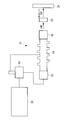
- FIG. 1 is a configuration diagram of an X-ray generator 10 according to the first embodiment.
- the X-ray generator 10 includes an electron gun 12, a linear accelerator 14, an X-ray target 16, a microwave generator 18, and a pulse modulator 20.
- the electron gun 12 generates an electron beam, and the generated electron beam is accelerated by the linear accelerator 14 and irradiated to the X-ray target 16.
- the X-ray target 16 generates X-rays corresponding to the energy of the electron beam by bremsstrahlung, and the X-ray is irradiated onto the inspection object 22.
- transmitted the test target object 22 is detected by the X-ray detector 24, and an X-ray fluoroscopic image will be obtained.
- the pulse modulator 20 generates a high voltage pulse, and the generated high voltage pulse is applied to the electron gun 12 and the microwave generator 18.
- the pulse modulator 20 changes the microwave power generated from the microwave generator 18 by changing the magnitude of the high voltage pulse.
- the electron gun 12 When the high voltage pulse is applied from the pulse modulator 20, the electron gun 12 generates an electron beam and makes it incident on the linear accelerator 14.
- the microwave generator 18 when a high voltage pulse is applied from the pulse modulator 20, the microwave generator 18 generates a microwave with large power (several megawatts (MW)) corresponding to the high voltage pulse and introduces it into the linear accelerator 14. .
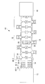
- FIG. 2 is a cross-sectional view of the linear accelerator 14 according to the first embodiment.
- the linear accelerator 14 includes a microwave introduction window 30, an acceleration tube 32, and a buncher unit 34.
- the acceleration tube 32 is configured by connecting a plurality of acceleration cavities 36 and has a plurality of side-coupled cavities 38.
- the buncher section 34 has a plurality of buncher cavities 40-1 to 40-5. In the following description, when distinguishing each buncher cavity 40, any one of 1 to 5 is added to the end of the reference numeral, and when not distinguishing each buncher cavity 40, 1 to 5 is omitted.
- the electron beam is accelerated to about 1 MeV by the buncher unit 34, that is, approximately to the speed of light, and further accelerated by the acceleration tube 32.
- the microwave generated by the microwave generator 18 is introduced from the microwave introduction window 30 to the acceleration tube 32.
- the microwave introduced from the microwave introduction window 30 passes through the acceleration cavity 36 and the side-coupled cavity 38 and excites an acceleration electric field in all the acceleration cavities 36.
- the microwave transmitted to the upstream acceleration cavity 36 closest to the electron gun 12 excites an acceleration electric field in the buncher cavity 40-5 via the side-coupled cavity 38.
- the microwaves transmitted to the buncher cavity 40-5 are further transmitted in the order of the buncher cavity 40-4, the buncher cavity 40-3, the buncher cavity 40-2, and the buncher cavity 40-1 via the beam hole. 40 accelerates an accelerating electric field.
- FIG. 3 is a graph showing an example of the acceleration electric field distribution of the linear accelerator 14 according to the first embodiment, where the horizontal axis indicates the position (z) on the central axis of the acceleration tube 32 and the vertical axis indicates the acceleration electric field. Intensity (Ez) is indicated.
- Each acceleration electric field A in FIG. 3 represents an acceleration electric field excited in the acceleration cavity 36
- an acceleration electric field B-5 represents an acceleration electric field excited in the buncher cavity 40-5
- an acceleration electric field B-3 represents the buncher cavity 40.
- ⁇ 3 indicates an acceleration electric field excited
- an acceleration electric field B-1 indicates an acceleration electric field excited in the buncher cavity 40-1. Note that the accelerating electric field oscillates in time according to the frequency of the microwave.
- the acceleration electric field A excited in the acceleration cavity 36 is 180 degrees out of phase with the adjacent acceleration cavity 36.
- the buncher cavity 40 according to the first embodiment is excited by a standing wave of ⁇ / 2 ( ⁇ / 2) mode, an accelerating electric field is generated in the buncher cavities 40-1, 40-3, and 40-5.
- the accelerating electric field is not excited in the buncher cavities 40-2 and 40-4.
- the electron beam generated by the electron gun 12 is incident on the buncher cavity 40-1 of the buncher unit 34 with the accelerating electric field excited in the buncher unit 34 and the accelerating tube 32.
- the electron beam incident on the buncher cavity 40-1 is gathered by the accelerating electric field while passing through the buncher cavity 40-2 to the buncher cavity 40-5, accelerated to almost the speed of light, and incident on the acceleration cavity 36. .
- the electron beam incident on the acceleration cavity 36 is synchronized with the acceleration phase of the acceleration electric field of the acceleration cavity 36 and further accelerated to high energy.
- the electron beam emitted from the acceleration cavity 36 is irradiated onto the X-ray target 16, and X-rays are generated from the X-ray target 16.
- the buncher unit 34 is composed of a plurality of buncher cavities 40, so that the microwave power to be introduced can be reduced without greatly reducing the intensity of the low energy electron beam compared to the rated operation. Obtainable. The reason for this is as follows.
- the electron beam incident on the buncher unit 34 from the electron gun 12 is gathered by the accelerating electric fields B-1, B-3, and B-5 excited in the buncher cavity 40, and is approximately at the speed of light. After being accelerated, the light is incident on the acceleration cavity 36.
- the buncher part 34 of the acceleration tube 32 decreases the microwave power introduced into the acceleration tube 32, the energy of electrons accelerated by the buncher part 34 decreases. The electron velocity decreases, and electrons are generated that fall behind the acceleration phase of the acceleration electric field B-3 or the acceleration electric field B-5.
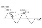
- electrons that have missed the acceleration electric field B-3 (n) (where n is the period of the introduced microwave) stay in the vicinity of the buncher cavity 40-3 or go backward in the direction of the buncher cavity 40-1.
- the electrons staying in the vicinity of the buncher cavity 40-3 are accelerated again (recaptured) at the acceleration phase (n + 1) of the next time period of the acceleration electric field B-3, and at the speed of light. It is possible to join the group of electrons that are gathered.
- electrons traveling backward in the direction of the buncher cavity 40-1 are again accelerated (recaptured) at the acceleration phase of the accelerating electric field B-1 excited in the buncher cavity 40-1, and are added to the group of electrons gathered at the speed of light. Can do. The same applies to electrons that have missed the acceleration phase of the acceleration electric field B-5.
- the buncher unit 34 is configured by the plurality of buncher cavities 40, so that even if the microwave power introduced into the linear accelerator 14 is reduced from the rated value (the microwave power during the rated operation), the buncher part 34 can be efficiently processed. Electrons can be gathered and accelerated to approximately the speed of light so that the electrons can enter the acceleration cavity 36.
- the linear accelerator 14 can accelerate the electron beam without greatly deviating from the acceleration phase of the acceleration electric field A even if the introduced microwave power is reduced.
- the linear accelerator 14 can re-enter the acceleration phase even if the electron beam incident from the electron gun 12 deviates from the acceleration phase of the buncher unit 34. Only by changing a certain microwave power, an electron beam having different energy can be emitted from one accelerator tube 32 without reducing the intensity (electron beam current) of the electron beam emitted from the linear accelerator 14. it can. Further, since the X-ray generator 10 according to the first embodiment does not need to optimize the energy of the electron beam generated by the electron gun 12 according to the energy of the electron beam emitted from the linear accelerator 14, The energy of the electron beam can be changed by simple control.
- the X-ray generator 10 can avoid a decrease in the electron beam current even when the energy of the electron beam emitted from the linear accelerator 14 is changed. Therefore, it is not necessary to increase the sensitivity range of the X-ray detector.
- the microwave power to be introduced when the microwave power to be introduced is reduced as compared with that during rated operation, the electrons that are out of the acceleration phase are recaptured by the plurality of buncher cavities 40, and therefore, the electron group in the acceleration axis direction
- the spread (phase spread) is larger than that during rated operation.
- the energy spectrum of an electron beam accelerated by microwave power lower than that during rated operation is broader than that during rated operation and contains many components on the low energy side.
- the electron beam has an effective energy lower than that of 1/2 power (1/2 power).
- the energy spectrum of X-rays (low-energy X-rays with a plurality of bunchers) generated by an electron beam accelerated with a microwave power lower than that during rated operation is obtained during rated operation.
- the energy is lower than the generated high energy X-rays.
- the effective energy of X-rays is also lower (less sharp) than the energy spectrum of conventional low-energy X-rays (without multiple bunchers). For this reason, the effective difference between the two energies of the high energy X-ray and the low energy X-ray obtained by the X-ray generator 10 according to the present embodiment is larger than that in the past.
- the conventional X-ray generator that generates low-energy X-rays referred to here reduces, for example, the microwave power introduced to a linear accelerator having a single buncher cavity from that during rated operation. It is a device that generates low energy X-rays.
- the X-ray generation apparatus 10 can obtain an X-ray transmission image with higher contrast that is useful for element identification that specifies the atomic number of the inspection object 22. Therefore, when the X-ray generator 10 is used for a nondestructive inspection apparatus such as a container and an element identification inspection is performed, both performance and cost reduction as a nondestructive inspection apparatus can be achieved.
- the X-ray generation apparatus 10 performs nondestructive inspection by the following method using, for example, a large bulk density such as a container as the inspection object 22.
- the X-ray generator 10 introduces microwave power during rated operation from the microwave generator 18 to the linear accelerator 14, accelerates the electron beam generated by the electron gun 12, and irradiates the X-ray target 16 to increase the power. Generate energy X-rays. The generated high-energy X-ray is irradiated onto the inspection object 22, and the X-ray transmitted through the inspection object 22 is detected by the X-ray detector 24 and processed as a transmission image. Thereafter, the X-ray generator 10 introduces a microwave having a power lower than that of the microwave at the rated operation from the microwave generator 18 to the linear accelerator 14 and is generated by the electron gun 12. The electron beam is accelerated and irradiated to the X-ray target 16 to generate X-rays.
- the generated low-energy X-ray is irradiated onto the inspection object 22, and the X-ray transmitted through the inspection object 22 is detected by the X-ray detector 24 and processed as a transmission image. Then, element identification of the inspection object 22 is performed based on two different types of X-ray transmission images detected by the X-ray detector 24.
- the X-ray generator 10 includes the electron gun 12 that generates an electron beam, the linear accelerator 14 that accelerates the electron beam generated by the electron gun 12 using microwaves, and the linear accelerator.
- the electron beam accelerated by 14 is irradiated, the X-ray target 16 that generates X-rays, the microwave generator 18 that generates microwaves to be introduced into the linear accelerator 14, and the power of the microwaves change.
- a pulse modulator 20 for controlling the microwave generator 18 is provided.
- the linear accelerator 14 has the some buncher cavity 40, even if the electron which shifted
- X-ray generator 10 which concerns on this 1st Embodiment produces
- X-rays are generated, and low-power X-rays are generated by introducing microwave power lower than the microwave power in the rated operation from the microwave generator 18 to the linear accelerator 14. That is, the X-ray generator 10 according to the first embodiment generates high-energy X-rays and low-energy X-rays based on the microwave power in rated operation, and thus easily generates X-rays having different energies. Can be made.
- the configuration of the X-ray generator 10 according to the second embodiment is the same as the configuration of the X-ray generator 10 according to the first embodiment shown in FIG.
- the linear accelerator 14 according to the second embodiment may not have the plurality of buncher cavities 40.
- the pulse modulator 20 according to the second embodiment can change the frequency (period) at which the microwave is repeatedly introduced in a pulse shape in accordance with the magnitude of the power of the microwave introduced into the linear accelerator 14. This is made possible by controlling the high voltage pulse output to the microwave generator 18.
- the X-ray generator 10 that obtains X-rays having different energies by lowering the microwave power to the linear accelerator 14 from the rated value varies depending on the energy of the electron beam emitted from the linear accelerator 14 and has a high energy.
- the low energy X-ray dose may be smaller than the X-ray dose. In such a case, since the X-ray dose incident on the X-ray detector 24 is different between high energy and low energy, it is necessary to increase the sensitivity range of the X-ray detector 24 for X-ray detection. .
- the frequency at which the microwave is repeatedly introduced in a pulse shape can be changed according to the magnitude of the microwave power introduced into the linear accelerator 14. Therefore, the amount of electron beam current can be increased or decreased according to the magnitude of the microwave power. Therefore, the X-ray generation apparatus 10 can make the X-ray dose irradiated to the inspection target 22 equal when generating high-energy X-rays and when generating low-energy X-rays.
- the low energy X-ray dose is 1/6 (1/6) of the high energy X-ray dose
- the low microwave power pulse is set to 120 Hz
- the high microwave power pulse is set to 20 Hz.
- the accelerating tube 32 and the buncher cavity 40 have been described with respect to the form in which a standing wave of ⁇ / 2 mode is excited.
- the present invention is not limited to this, and the buncher The cavity 40 may be configured such that an acceleration electric field is excited in all buncher cavities 40 by the ⁇ mode, or an acceleration electric field is excited in the buncher cavities 40 by other modes.
- the present invention is not limited to this and is emitted from the linear accelerator 14.
- the energy of the electron beam may be three or more.
Landscapes
- Physics & Mathematics (AREA)
- Engineering & Computer Science (AREA)
- Plasma & Fusion (AREA)
- Spectroscopy & Molecular Physics (AREA)
- X-Ray Techniques (AREA)
- Particle Accelerators (AREA)
Abstract
X線発生装置(10)は、電子ビームを発生させる電子銃(12)、電子銃(12)によって発生された電子ビームをマイクロ波によって加速させる線形加速器(14)、線形加速器(14)によって加速された電子ビームが照射されることによって、X線を発生するX線ターゲット(16)、線形加速器(14)に導入させるマイクロ波を発生するマイクロ波発生装置、マイクロ波の電力が変化するようにマイクロ波発生装置を制御するパルスモジュレータを備える。線形加速器(14)は、複数のバンチャ空洞(40)を有しているため、マイクロ波の電力を低下させることで加速位相からずれた電子が生じても、該電子を次の時間周期の加速位相にて加速させることができるので、マイクロ波の電力を低下させても出射される電子ビームの強度の低下が抑制される。
Description
本発明は、X線発生装置及びX線発生装置の制御方法に関するものである。
例えば、空港での手荷物検査等に用いられるエックス線(以下、「X線」という。)を利用した非破壊検査装置には、数十から数百キロボルト程度の管電圧で駆動するX線管が搭載されているものがある。このような非破壊検査装置は、X線管から出力されたX線を手荷物等の検査対象物に照射し、検査対象物を透過したX線の線量の空間分布から検査対象物の嵩密度(物質の比重と密度との積)の濃淡を画像として構成している。
また、上記非破壊検査装置は、各元素によってX線の減衰(線源弱係数)のX線エネルギ依存性が異なることを利用して、検査対象物の原子番号の特定(元素同定)を行う場合がある。このような元素同定を目的として、上記非破壊検査装置は、X線管の管電圧を変化させてX線を照射する、又は複数のX線管により異なる管電圧によるX線の照射を行い、例えば2つの異なる管電圧、すなわち2つの異なるX線のエネルギによる透視画像を得ることによって、検査対象物の原子番号を特定する。
また、上記非破壊検査装置は、各元素によってX線の減衰(線源弱係数)のX線エネルギ依存性が異なることを利用して、検査対象物の原子番号の特定(元素同定)を行う場合がある。このような元素同定を目的として、上記非破壊検査装置は、X線管の管電圧を変化させてX線を照射する、又は複数のX線管により異なる管電圧によるX線の照射を行い、例えば2つの異なる管電圧、すなわち2つの異なるX線のエネルギによる透視画像を得ることによって、検査対象物の原子番号を特定する。
一方、港湾や国境におけるコンテナ等の嵩密度の大きい荷物に対するX線を利用した非破壊検査では、数百キロボルト程度の管電圧で駆動するX線管から発生するX線では透過能力が不十分であり、より高エネルギのX線を用いた非破壊検査が行われている。
高エネルギのX線を得るためには、線形加速器(Linear Accelerator:LINAC)と呼ばれる加速器が主に用いられており、線形加速器によって高エネルギ(3MeVから9MeV程度)に加速させた電子が、ターゲット材料に照射されることにより、制動放射によってターゲット材料から高エネルギのX線が発生する。このように、線形加速器を用いた非破壊検査装置は、X線管で発生されるX線よりも高エネルギのX線を得ることができるため、コンテナ等の比較的嵩密度が大きい検査対象物に対してもX線を透過させ、透視画像を得ることができる。
ここで、線形加速器を用いたX線発生装置について説明する。
線形加速器を用いたX線発生装置は、電子銃、バンチャ、加速管、X線ターゲット、パルスモジュレータ、及びマイクロ波発生装置を備え、電子銃によって発生された電子ビームは、バンチャ及び加速管によって加速され、X線ターゲットに照射される。
より具体的には、パルスモジュレータは、高電圧パルスを発生させ、発生された高電圧パルスは、電子銃とマイクロ波発生装置に印加される。
電子銃は、パルスモジュレータから高電圧パルスが印加されると、電子ビームを発生させ、発生させた電子ビームをバンチャへ入射させる。なお、バンチャへ入射される電子ビームの電子密度は、高電圧パルス幅にわたって時間的に一様である。
一方、マイクロ波発生装置は、パルスモジュレータから高電圧パルスが印加されると、数メガワット(MW)の大電力のマイクロ波を発生させる。なお、高電圧パルスのパルス幅は、マイクロ波発生装置によって発生されるマイクロ波の周期よりも十分長い。
電子銃は、パルスモジュレータから高電圧パルスが印加されると、電子ビームを発生させ、発生させた電子ビームをバンチャへ入射させる。なお、バンチャへ入射される電子ビームの電子密度は、高電圧パルス幅にわたって時間的に一様である。
一方、マイクロ波発生装置は、パルスモジュレータから高電圧パルスが印加されると、数メガワット(MW)の大電力のマイクロ波を発生させる。なお、高電圧パルスのパルス幅は、マイクロ波発生装置によって発生されるマイクロ波の周期よりも十分長い。
そして、マイクロ波発生装置によって発生されたマイクロ波は、共振空洞が複数連結して構成された加速管へ入射される。なお、加速管を構成する共振空洞を加速空洞という。加速管へ入射されたマイクロ波は、各加速空洞によって共振され、各加速空洞において、マイクロ波の周波数によって振動する中心軸方向を向いた、電子ビームを加速させるための加速電界を励起させる。なお、隣接する加速空洞に励起される加速電界との位相差は、180度とされる。
また、バンチャも、共振空洞により構成されており、加速管へ入射されたマイクロ波は、加速管内部を伝わってバンチャにも加速電界を励起させる。そして、電子銃からバンチャへ入射された電子ビームは、バンチャで励起された加速電界により速度変調を受ける。すなわち、バンチャの加速電界が正となったタイミングでバンチャへ入射された電子ビームは増速する一方、加速電界が負となったタイミングでバンチャへ入射された電子ビームは減速する。
このため、バンチャへ入射した時点では高電圧パルス幅内で時間的に一様であった電子ビームの電子密度は、上記速度変調の影響を受けて、除々に集群(バンチング)され、マイクロ波の周波数で決定される時間周期で粗密を有するようになる。
このため、バンチャへ入射した時点では高電圧パルス幅内で時間的に一様であった電子ビームの電子密度は、上記速度変調の影響を受けて、除々に集群(バンチング)され、マイクロ波の周波数で決定される時間周期で粗密を有するようになる。
バンチャにおける共振空洞の形状は、バンチングされた電子ビームの電子密度の高い部分が加速管に入射されるタイミングと、加速管の最初の加速空洞の加速電界が正であるタイミングを同期させるように設計されており、このように同期させることによって、電子を正の加速電界で効率的に加速させることができ、かつ負の加速電界によって電子銃側へ逆行して加速される電子を減らすことができる。
なお、加速管において各々隣接する加速空洞の加速電界の位相差が180度とされているが、加速空洞の形状は、加速管の最初の加速空洞により加速された電子が隣接する加速空洞に到達するタイミングと、隣接する加速空洞の加速電界が正となるタイミングとを同期させるように設計されており、このように同期させることにより、電子はさらに加速される。線形加速器は、同様にして複数の加速空洞においても、加速電界が正となるタイミングで同期させながら電子を加速させることにより、目的とする高エネルギの電子ビームを発生させる。
そして、加速された高エネルギの電子ビームが、X線ターゲットに照射されることにより、高エネルギの制動放射X線が得られる。
さらに、線形加速器を用いた非破壊検査装置において元素同定を行う場合には、X線管の場合と同様に2つの異なる電子ビームのエネルギを持つ線形加速器が必要とされる。
例えば、手荷物検査を行うための非破壊検査装置で用いられるX線管の場合には、X線管の管電圧を変化させることにより容易に異なるエネルギのX線を得ることができる。またX線管は比較的安価であるため、2つのX線管を非破壊検査装置に搭載することが経済的に成立しえる。
しかしながら、線形加速器は、X線管に比べ高価であり、2つの異なる電子エネルギを得るために2つの異なる線形加速器を非破壊検査装置に搭載することは大きなコスト増の原因となる。
ここで、特許文献1には、加速管に入射するマイクロ波の電力(以下、「マイクロ波電力」という。)をP、電子ビームの電流値をI、電子ビームのエネルギをEとすると、下記(1)式に示される関係式が成り立つことが記載されている。なお、AとBは、定数である。

従って、加速管へ導入するマイクロ波電力を下げ、かつ電子ビームの電流を上げると、電子ビームのエネルギは低下する。
線形加速器は、(1)式に示される関係を利用して、高電圧パルスの電圧波高値を定格値に対して下げることによってマイクロ波増幅器から出力されるマイクロ波電力を下げ、電子銃のグリッド電圧を定格値に対して上げることによって電子銃で発生される電子ビームの電流値を上げることで、定格値よりも低い加速エネルギの電子ビームを出力することができる。そして、線形加速器は、このような制御をパルスモジュレータの高電圧パルスのパルス毎に切り換えることで、2つの異なる加速エネルギの電子ビームを発生させることができる。
しかしながら、特許文献1に記載されている制御方法によって、加速管へ導入するマイクロ波電力を低下させると以下のような問題が生じる。
加速管に入射するマイクロ波電力を定格値よりも低下させると加速空洞に励起される加速電界は小さくなる。すると加速される電子の速度が、定格のマイクロ波電力によって運転する定格運転時に比べて遅くなるため、1つの加速空洞を通過するのに要する時間が定格運転時に比べ長くなる。
加速管に入射するマイクロ波電力を定格値よりも低下させると加速空洞に励起される加速電界は小さくなる。すると加速される電子の速度が、定格のマイクロ波電力によって運転する定格運転時に比べて遅くなるため、1つの加速空洞を通過するのに要する時間が定格運転時に比べ長くなる。
このため電子が次の加速空洞に到達するタイミングが、定格運転時に比べて遅くなる。このタイミングが遅いため、次の共振駆動に電子が到達した時点では、次の加速空洞の加速電界の位相は正から負に変わろうとしてしまう。つまり、次の加速空洞に到達するタイミングが遅くなると、適正な正の加速電界により電子が加速されないこととなり、加速管で適正に加速されてX線ターゲットに到達する電子ビームの電流は小さくなってしまう。
上記のような電子が加速電界の正の位相に乗れないという問題は、加速管に電子が入射された最初の加速空洞で特に問題となる。この理由は以下の通りである。
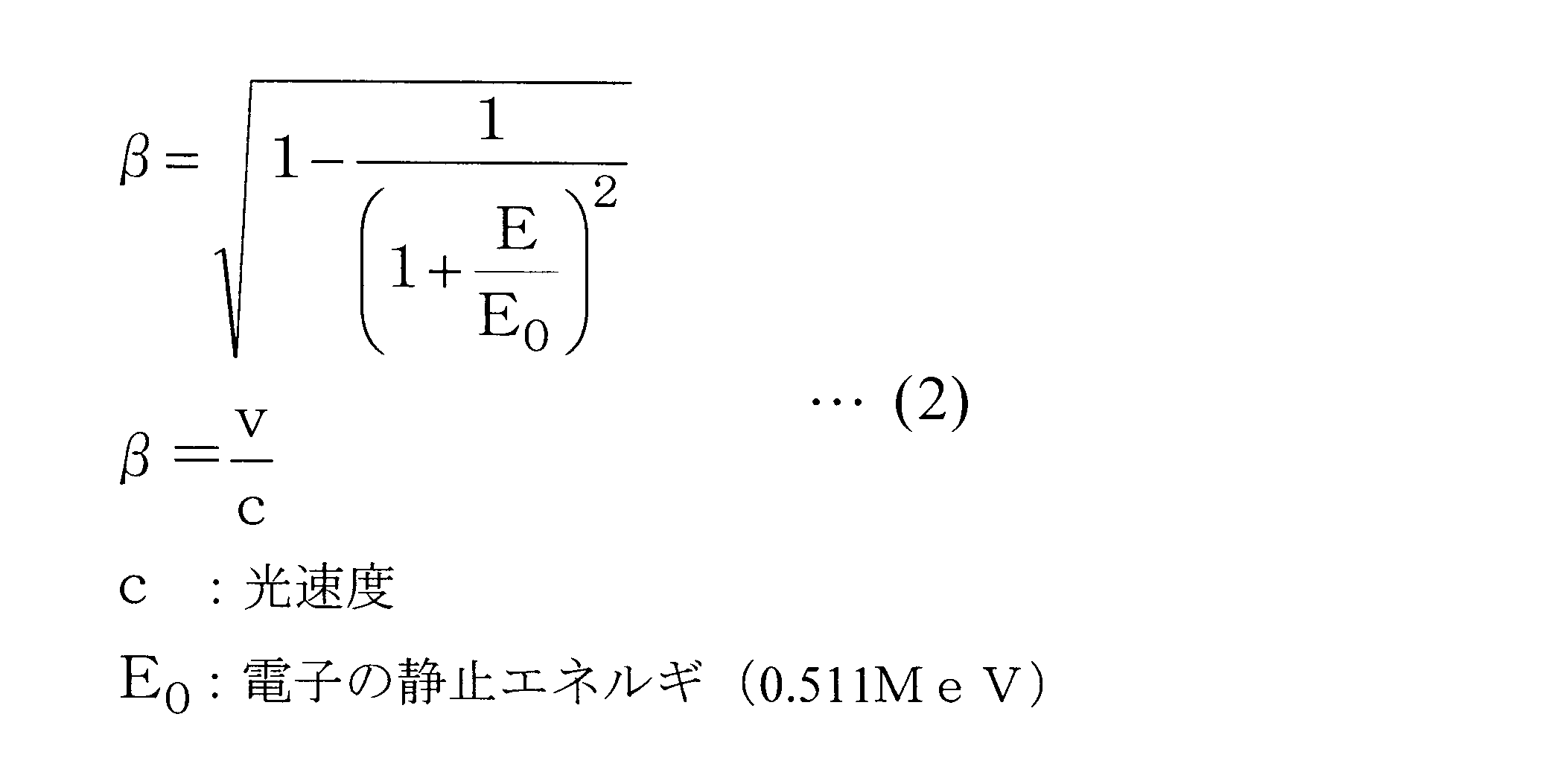
一般に高エネルギの電子の速度vと加速エネルギEは、下記(2)式で示すような関係が成り立つ。
一般に高エネルギの電子の速度vと加速エネルギEは、下記(2)式で示すような関係が成り立つ。
(2)式によると電子が静止状態から1MeVに加速されると、電子は、光速の94%の速度まで到達する。そして、電子は、エネルギが1MeV程度を超えると、加速されるほど速度の上限である光速に近づく。従って電子速度の変化(上昇)の大部分は1MeV程度に加速されるまでに起こり、1MeV程度を超えると速度変化は緩やかになる。
このため、マイクロ波電力の低下時に、電子が加速電界の正の位相に乗れないという問題は、加速管に電子が入射された最初の加速空洞で顕著となる。そして、この問題により、加速管で加速され、X線ターゲットに照射される電子ビームの電流値は小さくなり、その結果、発生するX線の線量も小さくなる。
また、一般に電子ビームがX線ターゲットに照射されて制動放射により発生するX線の線量は、電子ビームのエネルギが低くなるほど小さくなる。このため、電子ビームのエネルギが低くなるほど検査対象物を透過するX線の線量も小さくなり、低エネルギのX線を発生させる場合には、十分な画像を得るためのS/N比が得られず、又、X線検出器の感度域を広く確保する必要が生じる。
本発明は、このような事情に鑑みてなされたものであって、線形加速器から出射させる電子ビームのエネルギを異ならせても、発生させるX線の線量の変動を抑制できる、X線発生装置及びX線発生装置の制御方法を提供することを目的とする。
上記課題を解決するために、本発明のX線発生装置及びX線発生装置の制御方法は以下の手段を採用する。
本発明の第一態様に係るX線発生装置は、電子ビームを発生させる電子ビーム発生手段と、複数のバンチャ空洞と複数の加速空洞を有し、前記電子ビーム発生手段によって発生された電子ビームをマイクロ波によって加速させる線形加速器と、前記線形加速器によって加速された電子ビームが照射されることによって、X線を発生するターゲットと、前記線形加速器に導入させるマイクロ波を発生するマイクロ波発生手段と、マイクロ波の電力が変化するように前記マイクロ波発生手段を制御する制御手段と、を備える。
上記構成によれば、電子ビーム発生手段によって電子ビームを発生させ、複数のバンチャ空洞と複数の加速空洞を有する線形加速器によって、電子ビーム発生手段で発生された電子ビームをマイクロ波によって加速させ、線形加速器で加速された電子ビームをターゲットに照射することで、X線を発生させる。このようにして発生されたX線は、検査対象物に照射されることによって非破壊検査が行われる。
また、マイクロ波発生手段は、制御手段によって線形加速器へ導入されるマイクロ波の電力が変化するように制御される。マイクロ波の電力を変化させることによって、線形加速器で加速される電子ビームのエネルギが変化するので、ターゲットから発生するX線のエネルギも変化させることができ、異なるエネルギのX線を用いた検査対象物の元素同定が可能となる。
また、マイクロ波発生手段は、制御手段によって線形加速器へ導入されるマイクロ波の電力が変化するように制御される。マイクロ波の電力を変化させることによって、線形加速器で加速される電子ビームのエネルギが変化するので、ターゲットから発生するX線のエネルギも変化させることができ、異なるエネルギのX線を用いた検査対象物の元素同定が可能となる。
ここで、マイクロ波の電力を定格運転時よりも低下させると、電子ビームの速度が遅くなるため、加速空洞に到達するタイミングが定格運転時に比べて遅くなり、加速位相からずれ、適正な正の加速電界により電子を加速することができない。そのため、線形加速器から出射される電子ビームの強度は、定格運転で加速させた場合に比較して大幅に低下する。
しかしながら、線形加速器が複数のバンチャ空洞を有すると、電子ビームが加速位相からずれても、次の時間周期の加速位相にて加速されることとなる。そして、複数のバンチャを通過した電子ビームは、略光速まで加速されることとなるため、バンチャ空洞よりも下流側に位置する加速空洞を定格運転とほぼ同じ時間で通過することができる。
このように、本発明は、線形加速器が複数のバンチャを有することで、マイクロ波の電力を低下させることで加速位相からずれた電子が生じても、次の時間周期の加速位相にて加速される。従って、マイクロ波の電力を低下させても出射される電子ビームの強度の低下が抑制されるので、線形加速器から出射させる電子ビームのエネルギを異ならせても、発生させるX線の線量の変動を抑制できる。
また、上記第一態様では、前記制御手段が、前記マイクロ波発生手段から前記線形加速器へ導入させるマイクロ波の電力の大きさに応じて、該マイクロ波をパルス状に繰り返し導入する周波数を変化させることが好ましい。
線形加速装置から出射される電子ビームの強度が電子ビームのエネルギに応じて変化し、高エネルギのX線の線量に比べ、低エネルギのX線線量の方が小さくなると、感度域の広いX線検出器を用いる必要が生じる。
そこで、上記構成によれば、線形加速器へ導入するマイクロ波の電力の大きさに応じて、該マイクロ波をパルス状に繰り返し導入する周波数を変化させることが可能とされているので、マイクロ波の電力に応じて電子ビームの電流量を増減させることができる。従って、高エネルギのX線を発生させる場合と低エネルギのX線を発生させる場合とで、検査対象物へ照射させるX線線量を同等とできるため、X線検出器の感度域を広く取る必要がなくなる。
また、上記第一態様では、前記制御手段が、定格運転におけるマイクロ波の電力を前記マイクロ波発生手段から前記線形加速器へ導入させることで高エネルギのX線を発生させ、前記定格運転におけるマイクロ波の電力よりも低いマイクロ波の電力を前記マイクロ波発生手段から前記線形加速器へ導入させることで低エネルギのX線を発生させることが好ましい。
上記構成によれば、定格運転におけるマイクロ波の電力を基準として高エネルギのX線及び低エネルギのX線を発生させるので、容易に異なるエネルギのX線を発生させることができる。
本発明の第二態様に係るX線発生装置は、電子ビームを発生させる電子ビーム発生手段と、前記電子ビーム発生手段によって発生された電子ビームをマイクロ波によって加速させる線形加速器と、前記線形加速器によって加速された電子ビームが照射されることによって、X線を発生するターゲットと、前記線形加速器に導入させるマイクロ波を発生するマイクロ波発生手段と、マイクロ波の電力が変化するように前記マイクロ波発生手段を制御する制御手段と、を備え、前記制御手段は、前記マイクロ波発生手段から前記線形加速器へ導入させるマイクロ波の電力の大きさに応じて、該マイクロ波をパルス状に繰り返し導入する周波数を変化させる。
本発明の第三態様に係るX線発生装置の制御方法は、電子ビームを発生させる電子ビーム発生手段、複数のバンチャ空洞と複数の加速空洞を有し、前記電子ビーム発生手段によって発生された電子ビームをマイクロ波によって加速させる線形加速器、前記線形加速器によって加速された電子ビームが照射されることによって、X線を発生するターゲット、前記線形加速器に導入させるマイクロ波を発生するマイクロ波発生手段、及びマイクロ波の電力が変化するように前記マイクロ波発生手段を制御する制御手段を備えたX線発生装置の制御方法であって、第1の大きさのマイクロ波の電力を前記マイクロ波発生手段から前記線形加速器へ導入し、前記電子ビーム発生手段によって発生された電子ビームを加速させ、前記ターゲットに照射させてX線を発生させる第1工程と、前記第1の大きさのマイクロ波の電力とは異なる大きさの電力のマイクロ波を前記マイクロ波発生手段から前記線形加速器へ導入し、前記電子ビーム発生手段によって発生された電子ビームを加速させ、前記ターゲットに照射させてX線を発生させる第2工程と、を含む。
本発明によれば、線形加速器から出射させる電子ビームのエネルギを異ならせても、発生させるX線の線量の変動を抑制できる、という優れた効果を有する。
以下に、本発明に係るX線発生装置及びX線発生装置の制御方法の一実施形態について、図面を参照して説明する。
〔第1実施形態〕
以下、本発明の第1実施形態について説明する。
以下、本発明の第1実施形態について説明する。
図1は、本第1実施形態に係るX線発生装置10の構成図である。
図1に示されるようにX線発生装置10は、電子銃12、線形加速器14、X線ターゲット16、マイクロ波発生装置18、及びパルスモジュレータ20を備える。
図1に示されるようにX線発生装置10は、電子銃12、線形加速器14、X線ターゲット16、マイクロ波発生装置18、及びパルスモジュレータ20を備える。
電子銃12は、電子ビームを発生させ、発生された電子ビームは、線形加速器14によって加速され、X線ターゲット16に照射される。そして、X線ターゲット16は、制動放射によって電子ビームのエネルギに応じたX線を発生させ、該X線は、検査対象物22へ照射される。そして、検査対象物22を透過したX線は、X線検出器24によって検出され、X線透視画像が得られることとなる。
また、パルスモジュレータ20は、高電圧パルスを発生させ、発生された高電圧パルスは、電子銃12とマイクロ波発生装置18に印加される。パルスモジュレータ20は、高電圧パルスの大きさを変化させることによって、マイクロ波発生装置18から発生させるマイクロ波電力を変化させる。
電子銃12は、パルスモジュレータ20から高電圧パルスが印加されると、電子ビームを発生させて線形加速器14へ入射させる。一方、マイクロ波発生装置18は、パルスモジュレータ20から高電圧パルスが印加されると、高電圧パルスに応じた大電力(数メガワット(MW))のマイクロ波を発生させ、線形加速器14へ導入する。
図2は、本第1実施形態に係る線形加速器14の断面図である。
線形加速器14は、マイクロ波導入窓30、加速管32、バンチャ部34を備える。加速管32は、複数の加速空洞36が複数連結して構成されると共に、複数のサイドカップルド空洞38を有する。バンチャ部34は、複数のバンチャ空洞40-1~40-5を有する。なお、以下の説明において、各バンチャ空洞40を区別する場合は、符号の末尾に1~5の何れかを付し、各バンチャ空洞40を区別しない場合は、1~5を省略する。
電子ビームは、バンチャ部34によって1MeV程度、すなわち略光速まで加速され、加速管32によってさらに加速される。
マイクロ波発生装置18によって発生されたマイクロ波は、マイクロ波導入窓30から加速管32へ導入される。マイクロ波導入窓30から導入されたマイクロ波は、加速空洞36とサイドカップルド空洞38を通って、全ての加速空洞36に加速電界を励振する。
そして、最も電子銃12に近い上流側の加速空洞36に伝わったマイクロ波は、サイドカップルド空洞38を経由してバンチャ空洞40-5に加速電界を励振させる。
バンチャ空洞40-5に伝わったマイクロ波は、さらにビームホールを経由してバンチャ空洞40-4、バンチャ空洞40-3、バンチャ空洞40-2、バンチャ空洞40-1の順に伝達され、各バンチャ空洞40に加速電界を励振させる。
バンチャ空洞40-5に伝わったマイクロ波は、さらにビームホールを経由してバンチャ空洞40-4、バンチャ空洞40-3、バンチャ空洞40-2、バンチャ空洞40-1の順に伝達され、各バンチャ空洞40に加速電界を励振させる。
図3は、本第1実施形態に係る線形加速器14の加速電界分布の一例を示すグラフであり、横軸が加速管32の中心軸上の位置(z)を示し、縦軸が加速電界の強度(Ez)を示す。図3における各加速電界Aは、加速空洞36に励振される加速電界を示し、加速電界B-5はバンチャ空洞40-5に励振される加速電界を示し、加速電界B-3はバンチャ空洞40-3に励振される加速電界を示し、加速電界B-1はバンチャ空洞40-1に励振される加速電界を示す。なお、加速電界は、マイクロ波の周波数に応じて時間的に振動している。
図3に示されるように、加速空洞36に励振される加速電界Aは、隣接する加速空洞36とは位相が180度異なっている。
また、本第1実施形態に係るバンチャ空洞40は、π/2(2分のπ)モードの定在波を励振されるため、バンチャ空洞40-1,40-3,40-5に加速電界が励振される一方、バンチャ空洞40-2,40-4には加速電界が励振されない。
また、本第1実施形態に係るバンチャ空洞40は、π/2(2分のπ)モードの定在波を励振されるため、バンチャ空洞40-1,40-3,40-5に加速電界が励振される一方、バンチャ空洞40-2,40-4には加速電界が励振されない。
そして、線形加速器14は、バンチャ部34及び加速管32に加速電界が励振された状態で、電子銃12によって発生された電子ビームがバンチャ部34のバンチャ空洞40-1に入射される。
バンチャ空洞40-1に入射された電子ビームは、バンチャ空洞40-2からバンチャ空洞40-5までを通過する間に加速電界により集群されると共に略光速まで加速され、加速空洞36へ入射される。加速空洞36へ入射された電子ビームは、加速空洞36の加速電界の加速位相に同期され、さらに高エネルギへ加速される。
そして、加速空洞36から出射された電子ビームは、X線ターゲット16に照射され、X線ターゲット16からX線が発生する。
バンチャ空洞40-1に入射された電子ビームは、バンチャ空洞40-2からバンチャ空洞40-5までを通過する間に加速電界により集群されると共に略光速まで加速され、加速空洞36へ入射される。加速空洞36へ入射された電子ビームは、加速空洞36の加速電界の加速位相に同期され、さらに高エネルギへ加速される。
そして、加速空洞36から出射された電子ビームは、X線ターゲット16に照射され、X線ターゲット16からX線が発生する。
次に、線形加速器14が複数のバンチャ空洞40を備えることによる作用を説明する。
線形加速器14は、バンチャ部34が複数のバンチャ空洞40で構成されることにより、定格運転時と比べて低いエネルギの電子ビームの強度を大きく下げることなく、導入されるマイクロ波電力を下げるだけで得ることができる。この理由は、以下の通りである。
線形加速器14は、バンチャ部34が複数のバンチャ空洞40で構成されることにより、定格運転時と比べて低いエネルギの電子ビームの強度を大きく下げることなく、導入されるマイクロ波電力を下げるだけで得ることができる。この理由は、以下の通りである。
電子銃12からバンチャ部34へ入射された電子ビームは、上述したように、バンチャ空洞40に励振される加速電界B-1,B-3,B-5により電子ビームが集群され、かつ略光速まで加速された後に、加速空洞36に入射される。
ここで、本第1実施形態に係る加速管32のバンチャ部34は、加速管32へ導入されるマイクロ波電力を低下させると、バンチャ部34にて加速される電子のエネルギが低下するため、電子速度が低下し、加速電界B-3や加速電界B-5の加速位相に乗り遅れる電子が発生する。
例えば、加速電界B-3(n)(nは導入されるマイクロ波の周期)で乗り遅れた電子は、バンチャ空洞40-3近傍に滞留したり、バンチャ空洞40-1方向へ逆行したりする。
しかしながら、図4に示されるように、バンチャ空洞40-3近傍で滞留する電子は、加速電界B-3の次の時間周期の加速位相(n+1)にて再度加速され(再捕捉)、光速で集群される電子群に加わることができる。また、バンチャ空洞40-1方向へ逆行した電子もバンチャ空洞40-1に励振される加速電界B-1の加速位相にて再度加速され(再捕捉)、光速で集群される電子群に加わることができる。
なお、加速電界B-5の加速位相に乗り遅れた電子についても同様である。
なお、加速電界B-5の加速位相に乗り遅れた電子についても同様である。
このように、バンチャ部34は複数のバンチャ空洞40で構成されることによって、線形加速器14に導入されるマイクロ波電力を定格値(定格運転時におけるマイクロ波電力)から低下させても、効率よく電子を集群し略光速まで加速させ、加速空洞36に電子を入射させることができる。
さらに、マイクロ波電力が定格値から低下されても、加速空洞36に入射された電子ビーム(電子群)は、バンチャ部34における加速によって、すでに略光速まで加速されているため、バンチャ空洞よりも下流側に位置する加速空洞36を定格運転時と略同じ時間で通過することができる。このため、線形加速器14は、導入されるマイクロ波電力が低下されても、加速電界Aの加速位相から大きくずれることなく電子ビームを加速させることができる。
このように、本第1実施形態に係る線形加速器14は、電子銃12から入射された電子ビームがバンチャ部34の加速位相からずれても、再び加速位相に乗ることができるため、運転条件であるマイクロ波電力が変化されるだけで、線形加速器14から出射される電子ビームの強度(電子ビーム電流)を低下させることなく、異なるエネルギを持つ電子ビームを1つの加速管32で出射させることができる。
また、本第1実施形態に係るX線発生装置10は、線形加速器14から出射される電子ビームのエネルギに応じて、電子銃12で発生する電子ビームのエネルギを最適化する必要がないため、簡易な制御により電子ビームのエネルギを変更できる。
また、本第1実施形態に係るX線発生装置10は、線形加速器14から出射される電子ビームのエネルギに応じて、電子銃12で発生する電子ビームのエネルギを最適化する必要がないため、簡易な制御により電子ビームのエネルギを変更できる。
このように、本第1実施形態に係るX線発生装置10は、線形加速器14から出射させる電子ビームのエネルギを変化させても、電子ビーム電流の低下を回避できるので、十分な線量のX線を得ることができ、X線検出器の感度域を大きくとる必要がなくなる。
さらに、上記説明したように、導入するマイクロ波電力を定格運転時に比べて低下させた場合、複数のバンチャ空洞40によって加速位相からずれた電子が再補足されるため、電子群の加速軸方向の広がり(位相の広がり)は、定格運転時に比べて大きくなる。
このため、定格運転時に比べて低いマイクロ波電力で加速された電子ビームのエネルギスペクトルは、定格運転時のエネルギスペクトルに比べ広く,低エネルギ側の成分を多く含み、実効的にはマイクロ波電力の1/2乗(2分の1乗)よりもさらに低い実効エネルギを持つ電子ビームとなる。
このため、定格運転時に比べて低いマイクロ波電力で加速された電子ビームのエネルギスペクトルは、定格運転時のエネルギスペクトルに比べ広く,低エネルギ側の成分を多く含み、実効的にはマイクロ波電力の1/2乗(2分の1乗)よりもさらに低い実効エネルギを持つ電子ビームとなる。
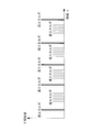
そして、図5に示されるように、定格運転時に比べて低いマイクロ波電力で加速された電子ビームによって発生されたX線のエネルギスペクトル(複数バンチャ有りの低エネルギのX線)は、定格運転で発生された高エネルギのX線よりもエネルギが低くなる。
さらに、X線の実効エネルギも、従来の低エネルギのX線(複数バンチャ無し)のエネルギスペクトルに比べて低くなる(シャープでなくなり)。このため、本実施形態に係るX線発生装置10によって得られる高エネルギのX線と低エネルギのX線の2つのエネルギの実効的な差は、従来に比較して大きくなる。なお、ここでいう、従来の低エネルギのX線を発生させるX線発生装置は、例えば、単一のバンチャ空洞を有する線形加速器に対して導入されるマイクロ波電力を定格運転時よりも低下させて低エネルギのX線を発生させる装置である。
さらに、X線の実効エネルギも、従来の低エネルギのX線(複数バンチャ無し)のエネルギスペクトルに比べて低くなる(シャープでなくなり)。このため、本実施形態に係るX線発生装置10によって得られる高エネルギのX線と低エネルギのX線の2つのエネルギの実効的な差は、従来に比較して大きくなる。なお、ここでいう、従来の低エネルギのX線を発生させるX線発生装置は、例えば、単一のバンチャ空洞を有する線形加速器に対して導入されるマイクロ波電力を定格運転時よりも低下させて低エネルギのX線を発生させる装置である。
この結果、本第1実施形態に係るX線発生装置10では、検査対象物22の原子番号を特定する元素同定に有用な、よりコントラストの大きいX線の透過画像を得ることができる。従って、X線発生装置10をコンテナ等の非破壊検査装置に用い、元素同定の検査を実施するにあたり、非破壊検査装置としての性能とコスト低減を両立できる。
なお、本第1実施形態に係るX線発生装置10は、例えば、コンテナ等の嵩密度の大きい荷物を検査対象物22として非破壊検査を、以下のような方法によって実行する。
X線発生装置10は、定格運転時のマイクロ波電力をマイクロ波発生装置18から線形加速器14へ導入し、電子銃12によって発生された電子ビームを加速させ、X線ターゲット16に照射させて高エネルギのX線を発生させる。発生された高エネルギのX線は、検査対象物22へ照射され、X線検出器24で検査対象物22を透過したX線が検出され、透過画像として処理される。
その後、X線発生装置10は、定格運転時の大きさのマイクロ波の電力よりも低い大きさの電力のマイクロ波をマイクロ波発生装置18から線形加速器14へ導入し、電子銃12によって発生された電子ビームを加速させ、X線ターゲット16に照射させてX線を発生させる。発生された低エネルギのX線は、上記検査対象物22へ照射され、X線検出器24で検査対象物22を透過したX線が検出され、透過画像として処理される。
そして、X線検出器24によって検出された2種類の異なるX線の透過画像に基づいて、検査対象物22の元素同定が行われる。
その後、X線発生装置10は、定格運転時の大きさのマイクロ波の電力よりも低い大きさの電力のマイクロ波をマイクロ波発生装置18から線形加速器14へ導入し、電子銃12によって発生された電子ビームを加速させ、X線ターゲット16に照射させてX線を発生させる。発生された低エネルギのX線は、上記検査対象物22へ照射され、X線検出器24で検査対象物22を透過したX線が検出され、透過画像として処理される。
そして、X線検出器24によって検出された2種類の異なるX線の透過画像に基づいて、検査対象物22の元素同定が行われる。
以上説明したように、本第1実施形態に係るX線発生装置10は、電子ビームを発生させる電子銃12、電子銃12によって発生された電子ビームをマイクロ波によって加速させる線形加速器14、線形加速器14によって加速された電子ビームが照射されることによって、X線を発生するX線ターゲット16、線形加速器14に導入させるマイクロ波を発生するマイクロ波発生装置18、マイクロ波の電力が変化するようにマイクロ波発生装置18を制御するパルスモジュレータ20を備える。
そして、線形加速器14は、複数のバンチャ空洞40を有しているため、マイクロ波の電力を低下させることで加速位相からずれた電子が生じても、該電子を次の時間周期の加速位相にて加速させることができる。従って、マイクロ波の電力を低下させても出射される電子ビームの強度の低下が抑制されるので、線形加速器14から出射させる電子ビームのエネルギを異ならせても、発生させるX線の線量の変動を抑制できる。
そして、線形加速器14は、複数のバンチャ空洞40を有しているため、マイクロ波の電力を低下させることで加速位相からずれた電子が生じても、該電子を次の時間周期の加速位相にて加速させることができる。従って、マイクロ波の電力を低下させても出射される電子ビームの強度の低下が抑制されるので、線形加速器14から出射させる電子ビームのエネルギを異ならせても、発生させるX線の線量の変動を抑制できる。
また、本第1実施形態に係るX線発生装置10は、異なるエネルギのX線を発生させる場合、定格運転におけるマイクロ波電力をマイクロ波発生装置18から線形加速器14へ導入させることで高エネルギのX線を発生させ、定格運転におけるマイクロ波電力よりも低いマイクロ波電力をマイクロ波発生装置18から線形加速器14へ導入させることで低エネルギのX線を発生させる。
すなわち、本第1実施形態に係るX線発生装置10は、定格運転におけるマイクロ波電力を基準として高エネルギのX線及び低エネルギのX線を発生させるので、容易に異なるエネルギのX線を発生させることができる。
すなわち、本第1実施形態に係るX線発生装置10は、定格運転におけるマイクロ波電力を基準として高エネルギのX線及び低エネルギのX線を発生させるので、容易に異なるエネルギのX線を発生させることができる。
〔第2実施形態〕
以下、本発明の第2実施形態について説明する。
以下、本発明の第2実施形態について説明する。
本第2実施形態に係るX線発生装置10の構成は、図1に示す第1実施形態に係るX線発生装置10の構成と同様である。しかし、本第2実施形態に係る線形加速器14は、複数のバンチャ空洞40を有してなくてもよい。
そして、本第2実施形態に係るパルスモジュレータ20は、線形加速器14へ導入するマイクロ波の電力の大きさに応じて、該マイクロ波をパルス状に繰り返し導入する周波数(周期)を変化させることが、マイクロ波発生装置18へ出力する高電圧パルスを制御することによって可能とされている。
そして、本第2実施形態に係るパルスモジュレータ20は、線形加速器14へ導入するマイクロ波の電力の大きさに応じて、該マイクロ波をパルス状に繰り返し導入する周波数(周期)を変化させることが、マイクロ波発生装置18へ出力する高電圧パルスを制御することによって可能とされている。
線形加速器14へのマイクロ波電力を定格値から低下させることにより異なるエネルギのX線を得るX線発生装置10は、線形加速器14から出射される電子ビームのエネルギに応じて変化し、高エネルギのX線線量に比べ、低エネルギのX線線量の方が小さくなる場合がある。
このような場合、X線検出器24に入射するX線線量が高エネルギ時と低エネルギ時で異なることとなるため、X線検出器24のX線の検知に対する感度域を大きくする必要が生じる。
このような場合、X線検出器24に入射するX線線量が高エネルギ時と低エネルギ時で異なることとなるため、X線検出器24のX線の検知に対する感度域を大きくする必要が生じる。
そこで、本第2実施形態に係るX線発生装置10では、線形加速器14へ導入するマイクロ波電力の大きさに応じて、該マイクロ波をパルス状に繰り返し導入する周波数を変化させることが可能とされているので、マイクロ波電力の大きさに応じて電子ビームの電流量を増減させることができる。従って、X線発生装置10は、高エネルギのX線を発生させる場合と低エネルギのX線を発生させる場合とで、検査対象物22へ照射させるX線線量を同等とできる。
例えば、低エネルギのX線線量が高エネルギのX線線量に比べて1/6(6分の1)である場合、低いマイクロ波電力のパルスを120Hzとし、高いマイクロ波電力のパルスを20Hzとして線形加速器14へ導入することによって、図6に示されるようなX線線量の時間分布とし、低エネルギのX線と高エネルギのX線とで同程度のX線線量とすることができる。
従って、本第2実施形態に係るX線発生装置10では、X線検出器24の感度域を広く取る必要がなくなり、精度の高いX線検出システムとすることができる。
従って、本第2実施形態に係るX線発生装置10では、X線検出器24の感度域を広く取る必要がなくなり、精度の高いX線検出システムとすることができる。
以上、本発明を、上記各実施形態を用いて説明したが、本発明の技術的範囲は上記実施形態に記載の範囲には限定されない。発明の要旨を逸脱しない範囲で上記各実施形態に多様な変更または改良を加えることができ、該変更または改良を加えた形態も本発明の技術的範囲に含まれる。
例えば、上記各実施形態では、加速管32、及びバンチャ空洞40は、π/2モードの定在波が励振される形態について説明したが、本発明は、これに限定されるものではなく、バンチャ空洞40は、πモードによって全てのバンチャ空洞40に加速電界が励振されたり、他のモードによってバンチャ空洞40に加速電界が励振される形態としてもよい。
また、上記各実施形態では、線形加速器14から出射される電子ビームのエネルギを2種類とする形態について説明したが、本発明は、これに限定されるものではなく、線形加速器14から出射される電子ビームのエネルギを3種類以上とする形態としてもよい。
10 X線発生装置
12 電子銃
14 線形加速器
16 X線ターゲット
18 マイクロ波発生装置
20 パルスモジュレータ
36 加速空洞
40 バンチャ空洞
12 電子銃
14 線形加速器
16 X線ターゲット
18 マイクロ波発生装置
20 パルスモジュレータ
36 加速空洞
40 バンチャ空洞
Claims (5)
- 電子ビームを発生させる電子ビーム発生手段と、
複数のバンチャ空洞と複数の加速空洞を有し、前記電子ビーム発生手段によって発生された電子ビームをマイクロ波によって加速させる線形加速器と、
前記線形加速器によって加速された電子ビームが照射されることによって、X線を発生するターゲットと、
前記線形加速器に導入させるマイクロ波を発生するマイクロ波発生手段と、
マイクロ波の電力が変化するように前記マイクロ波発生手段を制御する制御手段と、
を備えたX線発生装置。 - 前記制御手段は、前記マイクロ波発生手段から前記線形加速器へ導入させるマイクロ波の電力の大きさに応じて、該マイクロ波をパルス状に繰り返し導入する周波数を変化させる請求項1記載のX線発生装置。
- 前記制御手段は、定格運転におけるマイクロ波の電力を前記マイクロ波発生手段から前記線形加速器へ導入させることで高エネルギのX線を発生させ、前記定格運転におけるマイクロ波の電力よりも低いマイクロ波の電力を前記マイクロ波発生手段から前記線形加速器へ導入させることで低エネルギのX線を発生させる請求項1又は請求項2記載のX線発生装置。
- 電子ビームを発生させる電子ビーム発生手段と、
前記電子ビーム発生手段によって発生された電子ビームをマイクロ波によって加速させる線形加速器と、
前記線形加速器によって加速された電子ビームが照射されることによって、X線を発生するターゲットと、
前記線形加速器に導入させるマイクロ波を発生するマイクロ波発生手段と、
マイクロ波の電力が変化するように前記マイクロ波発生手段を制御する制御手段と、
を備え、
前記制御手段は、前記マイクロ波発生手段から前記線形加速器へ導入させるマイクロ波の電力の大きさに応じて、該マイクロ波をパルス状に繰り返し導入する周波数を変化させるX線発生装置。 - 電子ビームを発生させる電子ビーム発生手段、複数のバンチャ空洞と複数の加速空洞を有し、前記電子ビーム発生手段によって発生された電子ビームをマイクロ波によって加速させる線形加速器、前記線形加速器によって加速された電子ビームが照射されることによって、X線を発生するターゲット、前記線形加速器に導入させるマイクロ波を発生するマイクロ波発生手段、及びマイクロ波の電力が変化するように前記マイクロ波発生手段を制御する制御手段を備えたX線発生装置の制御方法であって、
第1の大きさのマイクロ波の電力を前記マイクロ波発生手段から前記線形加速器へ導入し、前記電子ビーム発生手段によって発生された電子ビームを加速させ、前記ターゲットに照射させてX線を発生させる第1工程と、
前記第1の大きさのマイクロ波の電力とは異なる大きさの電力のマイクロ波を前記マイクロ波発生手段から前記線形加速器へ導入し、前記電子ビーム発生手段によって発生された電子ビームを加速させ、前記ターゲットに照射させてX線を発生させる第2工程と、
を含むX線発生装置の制御方法。
Priority Applications (3)
| Application Number | Priority Date | Filing Date | Title |
|---|---|---|---|
| CN201280018764.2A CN103493604A (zh) | 2011-07-22 | 2012-01-24 | X射线产生装置以及x射线产生装置的控制方法 |
| US14/114,624 US20140079189A1 (en) | 2011-07-22 | 2012-01-24 | X-ray generating device and x-ray-generating-device control |
| EP12817768.0A EP2736307A4 (en) | 2011-07-22 | 2012-01-24 | X-RAY GENERATING DEVICE AND METHOD FOR CONTROLLING X-RAY GENERATING DEVICE |
Applications Claiming Priority (2)
| Application Number | Priority Date | Filing Date | Title |
|---|---|---|---|
| JP2011160857A JP2013026070A (ja) | 2011-07-22 | 2011-07-22 | X線発生装置及びx線発生装置の制御方法 |
| JP2011-160857 | 2011-07-22 |
Publications (1)
| Publication Number | Publication Date |
|---|---|
| WO2013014953A1 true WO2013014953A1 (ja) | 2013-01-31 |
Family
ID=47600814
Family Applications (1)
| Application Number | Title | Priority Date | Filing Date |
|---|---|---|---|
| PCT/JP2012/051436 Ceased WO2013014953A1 (ja) | 2011-07-22 | 2012-01-24 | X線発生装置及びx線発生装置の制御方法 |
Country Status (5)
| Country | Link |
|---|---|
| US (1) | US20140079189A1 (ja) |
| EP (1) | EP2736307A4 (ja) |
| JP (1) | JP2013026070A (ja) |
| CN (1) | CN103493604A (ja) |
| WO (1) | WO2013014953A1 (ja) |
Cited By (1)
| Publication number | Priority date | Publication date | Assignee | Title |
|---|---|---|---|---|
| CN114466500A (zh) * | 2020-11-10 | 2022-05-10 | 西门子医疗有限公司 | 闭环控制借助于直线加速器系统生成的x射线脉冲链 |
Families Citing this family (7)
| Publication number | Priority date | Publication date | Assignee | Title |
|---|---|---|---|---|
| CN104320904B (zh) * | 2014-10-21 | 2018-12-04 | 明建川 | 微波电子加速器 |
| CN106455288A (zh) * | 2016-10-28 | 2017-02-22 | 中广核中科海维科技发展有限公司 | 一种能量可调节电子直线加速器 |
| KR101890514B1 (ko) * | 2017-01-31 | 2018-08-21 | 성균관대학교산학협력단 | 위상 집속 효과를 이용하여 전자빔을 생성하는 방법 및 선형 가속기 |
| CN108811297A (zh) * | 2017-05-03 | 2018-11-13 | 王云 | 一种医用质子重离子加速器 |
| CN109922593B (zh) * | 2017-12-13 | 2024-05-14 | 中国科学院大连化学物理研究所 | 电子能量阈值在线监控辐射安全联锁系统装置 |
| US10750607B2 (en) * | 2018-12-11 | 2020-08-18 | Aet, Inc. | Compact standing-wave linear accelerator structure |
| CN119815664A (zh) * | 2024-12-09 | 2025-04-11 | 中国原子能科学研究院 | 一种电子加速器 |
Citations (4)
| Publication number | Priority date | Publication date | Assignee | Title |
|---|---|---|---|---|
| JPH03283399A (ja) * | 1990-03-30 | 1991-12-13 | Toshiba Corp | 線形加速器 |
| JP2008218053A (ja) * | 2007-02-28 | 2008-09-18 | Accuthera Inc | 加速装置および加速装置を用いたx線発生装置 |
| JP2009205884A (ja) * | 2008-02-27 | 2009-09-10 | Accuthera Inc | 小径の電子ビームを発生する加速器 |
| US7646851B2 (en) | 2006-05-19 | 2010-01-12 | Tsinghua University | Device and method for generating X-rays having different energy levels and material discrimination system |
Family Cites Families (8)
| Publication number | Priority date | Publication date | Assignee | Title |
|---|---|---|---|---|
| US4286192A (en) * | 1979-10-12 | 1981-08-25 | Varian Associates, Inc. | Variable energy standing wave linear accelerator structure |
| US6493424B2 (en) * | 2001-03-05 | 2002-12-10 | Siemens Medical Solutions Usa, Inc. | Multi-mode operation of a standing wave linear accelerator |
| US6465957B1 (en) * | 2001-05-25 | 2002-10-15 | Siemens Medical Solutions Usa, Inc. | Standing wave linear accelerator with integral prebunching section |
| US6366641B1 (en) * | 2001-05-25 | 2002-04-02 | Siemens Medical Solutions Usa, Inc. | Reducing dark current in a standing wave linear accelerator |
| CA2427541C (en) * | 2001-08-24 | 2013-04-16 | Mitsubishi Heavy Industries, Ltd. | Radiotherapy apparatus |
| CN1220411C (zh) * | 2003-07-26 | 2005-09-21 | 中国工程物理研究院应用电子学研究所 | 一种驻波电子直线加速器 |
| US8183801B2 (en) * | 2008-08-12 | 2012-05-22 | Varian Medical Systems, Inc. | Interlaced multi-energy radiation sources |
| US8203289B2 (en) * | 2009-07-08 | 2012-06-19 | Accuray, Inc. | Interleaving multi-energy x-ray energy operation of a standing wave linear accelerator using electronic switches |
-
2011
- 2011-07-22 JP JP2011160857A patent/JP2013026070A/ja not_active Withdrawn
-
2012
- 2012-01-24 WO PCT/JP2012/051436 patent/WO2013014953A1/ja not_active Ceased
- 2012-01-24 CN CN201280018764.2A patent/CN103493604A/zh active Pending
- 2012-01-24 EP EP12817768.0A patent/EP2736307A4/en not_active Withdrawn
- 2012-01-24 US US14/114,624 patent/US20140079189A1/en not_active Abandoned
Patent Citations (4)
| Publication number | Priority date | Publication date | Assignee | Title |
|---|---|---|---|---|
| JPH03283399A (ja) * | 1990-03-30 | 1991-12-13 | Toshiba Corp | 線形加速器 |
| US7646851B2 (en) | 2006-05-19 | 2010-01-12 | Tsinghua University | Device and method for generating X-rays having different energy levels and material discrimination system |
| JP2008218053A (ja) * | 2007-02-28 | 2008-09-18 | Accuthera Inc | 加速装置および加速装置を用いたx線発生装置 |
| JP2009205884A (ja) * | 2008-02-27 | 2009-09-10 | Accuthera Inc | 小径の電子ビームを発生する加速器 |
Non-Patent Citations (1)
| Title |
|---|
| See also references of EP2736307A4 * |
Cited By (2)
| Publication number | Priority date | Publication date | Assignee | Title |
|---|---|---|---|---|
| CN114466500A (zh) * | 2020-11-10 | 2022-05-10 | 西门子医疗有限公司 | 闭环控制借助于直线加速器系统生成的x射线脉冲链 |
| US11516902B2 (en) | 2020-11-10 | 2022-11-29 | Siemens Healthcare Gmbh | Closed-loop control of an X-ray pulse chain generated by means of a linear accelerator system |
Also Published As
| Publication number | Publication date |
|---|---|
| JP2013026070A (ja) | 2013-02-04 |
| EP2736307A4 (en) | 2015-03-25 |
| EP2736307A1 (en) | 2014-05-28 |
| CN103493604A (zh) | 2014-01-01 |
| US20140079189A1 (en) | 2014-03-20 |
Similar Documents
| Publication | Publication Date | Title |
|---|---|---|
| WO2013014953A1 (ja) | X線発生装置及びx線発生装置の制御方法 | |
| US8541756B1 (en) | Systems and methods for generating X-rays and neutrons using a single linear accelerator | |
| EP3427553B1 (en) | Hybrid standing wave/traveling wave linear accelerators for providing accelerated charged particles or radiation beams and method with the same | |
| US9258876B2 (en) | Traveling wave linear accelerator based x-ray source using pulse width to modulate pulse-to-pulse dosage | |
| US20120081042A1 (en) | Traveling wave linear accelerator based x-ray source using current to modulate pulse-to-pulse dosage | |
| US20230082458A1 (en) | Method and apparatus for processing a particle shower using a laser-driven plasma | |
| US8716958B2 (en) | Microwave device for accelerating electrons | |
| Shiltsev | Experience with crystals at Fermilab accelerators | |
| Walker | Synchrotron radiation | |
| WO2016166549A1 (en) | Coherent radiation source | |
| Gilljohann et al. | Channeling acceleration in crystals and nanostructures and studies of solid plasmas: new opportunities | |
| WO2012132156A1 (ja) | X線発生装置及びx線発生装置の制御方法 | |
| Urakawa | Development of a compact X-ray source based on Compton scattering using a 1.3 GHz superconducting RF accelerating linac and a new laser storage cavity | |
| Amatuni et al. | Experimental demonstration of ballistic bunching with dielectric-lined waveguides at PITZ | |
| Shin et al. | Ultra-high gradient channeling acceleration in nanostructures: Design/progress of proof-of-concept (POC) experiments | |
| Wood et al. | Enhanced betatron radiation from a laser wakefield accelerator in a long focal length geometry | |
| JP2013048028A (ja) | X線照射装置および高周波電力生成ユニット | |
| Fukuda et al. | Status and future plan of the development of a compact x-ray source based on ICS at Laser Undulator Compact Xray (LUCX) | |
| JP2012003843A (ja) | 対物レンズ系及び電子顕微鏡 | |
| Hwang et al. | Radiation generation with an existing demonstrator of an energy-recovery continuous-wave superconducting rf accelerator | |
| Fukuda et al. | DEVELOPMENT AND UPGRADE PLAN OF AN X-RAY SOURCE BASED ON LASER COMPTON SCATTERING IN LASER UNDULATOR COM-PACT X-RAY SOURCE (LUCX) | |
| Khan et al. | Accelerator-Based Photon Sources | |
| Gschwendtner | AWAKE: advanced proton driven plasma wakefield acceleration experiment at CERN | |
| Wang et al. | Twin-bunch compression via velocity bunching in a traveling wave accelerator | |
| Yampolsky et al. | Summary of Working Group 7: Radiation generation and advanced concepts |
Legal Events
| Date | Code | Title | Description |
|---|---|---|---|
| 121 | Ep: the epo has been informed by wipo that ep was designated in this application |
Ref document number: 12817768 Country of ref document: EP Kind code of ref document: A1 |
|
| WWE | Wipo information: entry into national phase |
Ref document number: 14114624 Country of ref document: US |
|
| REEP | Request for entry into the european phase |
Ref document number: 2012817768 Country of ref document: EP |
|
| WWE | Wipo information: entry into national phase |
Ref document number: 2012817768 Country of ref document: EP |
|
| NENP | Non-entry into the national phase |
Ref country code: DE |