WO2013015191A1 - 起動制御方法、系統連系装置、及び制御装置 - Google Patents
起動制御方法、系統連系装置、及び制御装置 Download PDFInfo
- Publication number
- WO2013015191A1 WO2013015191A1 PCT/JP2012/068326 JP2012068326W WO2013015191A1 WO 2013015191 A1 WO2013015191 A1 WO 2013015191A1 JP 2012068326 W JP2012068326 W JP 2012068326W WO 2013015191 A1 WO2013015191 A1 WO 2013015191A1
- Authority
- WO
- WIPO (PCT)
- Prior art keywords
- power
- grid
- output
- pcs
- solar cell
- Prior art date
- Legal status (The legal status is an assumption and is not a legal conclusion. Google has not performed a legal analysis and makes no representation as to the accuracy of the status listed.)
- Ceased
Links
Images


Classifications
-
- H—ELECTRICITY
- H02—GENERATION; CONVERSION OR DISTRIBUTION OF ELECTRIC POWER
- H02J—ELECTRIC POWER NETWORKS; CIRCUIT ARRANGEMENTS OR SYSTEMS FOR SUPPLYING OR DISTRIBUTING ELECTRIC POWER; SYSTEMS FOR STORING ELECTRIC ENERGY
- H02J3/00—Circuit arrangements for AC mains or AC distribution networks
- H02J3/28—Arrangements for balancing of the load in networks by storage of energy
- H02J3/32—Arrangements for balancing of the load in networks by storage of energy using batteries or super capacitors with converting means
-
- H—ELECTRICITY
- H02—GENERATION; CONVERSION OR DISTRIBUTION OF ELECTRIC POWER
- H02J—ELECTRIC POWER NETWORKS; CIRCUIT ARRANGEMENTS OR SYSTEMS FOR SUPPLYING OR DISTRIBUTING ELECTRIC POWER; SYSTEMS FOR STORING ELECTRIC ENERGY
- H02J3/00—Circuit arrangements for AC mains or AC distribution networks
- H02J3/007—Arrangements for selectively connecting one or more loads to one or more power sources or power lines
- H02J3/0073—Arrangements for selectively connecting one or more loads to one or more power sources or power lines by providing alternative feeding paths when the main path fails
-
- H—ELECTRICITY
- H02—GENERATION; CONVERSION OR DISTRIBUTION OF ELECTRIC POWER
- H02J—ELECTRIC POWER NETWORKS; CIRCUIT ARRANGEMENTS OR SYSTEMS FOR SUPPLYING OR DISTRIBUTING ELECTRIC POWER; SYSTEMS FOR STORING ELECTRIC ENERGY
- H02J3/00—Circuit arrangements for AC mains or AC distribution networks
- H02J3/38—Arrangements for feeding a single network from two or more generators or sources in parallel; Arrangements for feeding already energised networks from additional generators or sources in parallel
- H02J3/381—Dispersed generators
-
- H—ELECTRICITY
- H02—GENERATION; CONVERSION OR DISTRIBUTION OF ELECTRIC POWER
- H02J—ELECTRIC POWER NETWORKS; CIRCUIT ARRANGEMENTS OR SYSTEMS FOR SUPPLYING OR DISTRIBUTING ELECTRIC POWER; SYSTEMS FOR STORING ELECTRIC ENERGY
- H02J7/00—Circuit arrangements for charging or discharging batteries or for supplying loads from batteries
- H02J7/34—Parallel operation in networks using both storage and other DC sources, e.g. providing buffering
- H02J7/35—Parallel operation in networks using both storage and other DC sources, e.g. providing buffering with light sensitive cells
-
- H—ELECTRICITY
- H02—GENERATION; CONVERSION OR DISTRIBUTION OF ELECTRIC POWER
- H02J—ELECTRIC POWER NETWORKS; CIRCUIT ARRANGEMENTS OR SYSTEMS FOR SUPPLYING OR DISTRIBUTING ELECTRIC POWER; SYSTEMS FOR STORING ELECTRIC ENERGY
- H02J2101/00—Supply or distribution of decentralised, dispersed or local electric power generation
- H02J2101/20—Dispersed power generation using renewable energy sources
- H02J2101/22—Solar energy
- H02J2101/24—Photovoltaics
-
- H—ELECTRICITY
- H02—GENERATION; CONVERSION OR DISTRIBUTION OF ELECTRIC POWER
- H02J—ELECTRIC POWER NETWORKS; CIRCUIT ARRANGEMENTS OR SYSTEMS FOR SUPPLYING OR DISTRIBUTING ELECTRIC POWER; SYSTEMS FOR STORING ELECTRIC ENERGY
- H02J3/00—Circuit arrangements for AC mains or AC distribution networks
- H02J3/04—Arrangements for connecting networks of the same frequency but supplied from different sources
- H02J3/08—Synchronisation of networks
-
- Y—GENERAL TAGGING OF NEW TECHNOLOGICAL DEVELOPMENTS; GENERAL TAGGING OF CROSS-SECTIONAL TECHNOLOGIES SPANNING OVER SEVERAL SECTIONS OF THE IPC; TECHNICAL SUBJECTS COVERED BY FORMER USPC CROSS-REFERENCE ART COLLECTIONS [XRACs] AND DIGESTS
- Y02—TECHNOLOGIES OR APPLICATIONS FOR MITIGATION OR ADAPTATION AGAINST CLIMATE CHANGE
- Y02E—REDUCTION OF GREENHOUSE GAS [GHG] EMISSIONS, RELATED TO ENERGY GENERATION, TRANSMISSION OR DISTRIBUTION
- Y02E10/00—Energy generation through renewable energy sources
- Y02E10/50—Photovoltaic [PV] energy
- Y02E10/56—Power conversion systems, e.g. maximum power point trackers
-
- Y—GENERAL TAGGING OF NEW TECHNOLOGICAL DEVELOPMENTS; GENERAL TAGGING OF CROSS-SECTIONAL TECHNOLOGIES SPANNING OVER SEVERAL SECTIONS OF THE IPC; TECHNICAL SUBJECTS COVERED BY FORMER USPC CROSS-REFERENCE ART COLLECTIONS [XRACs] AND DIGESTS
- Y02—TECHNOLOGIES OR APPLICATIONS FOR MITIGATION OR ADAPTATION AGAINST CLIMATE CHANGE
- Y02E—REDUCTION OF GREENHOUSE GAS [GHG] EMISSIONS, RELATED TO ENERGY GENERATION, TRANSMISSION OR DISTRIBUTION
- Y02E70/00—Other energy conversion or management systems reducing GHG emissions
- Y02E70/30—Systems combining energy storage with energy generation of non-fossil origin
Definitions
- the present invention relates to a startup control method, a grid interconnection device, and a control device that control startup of a grid interconnection device to which output power of a solar cell is input.
- the grid interconnection device has a grid interconnection relay for disconnecting the solar cell from the grid (see, for example, Patent Document 1).
- the grid interconnection device detects a state in which the output power amount of the grid interconnection device is too small relative to the power consumption of the load (for example, at night), and turns off the grid interconnection relay to remove the solar cell from the grid. It is configured to perform a grid stop control for disconnecting and stopping the operation of the grid interconnection device.
- the grid interconnection device detects a state in which the output power of the solar battery is obtained, and turns on the grid interconnection relay to link the solar battery to the grid and perform start-up control to start the grid operation. .
- the grid interconnection device when the grid interconnection device is activated, if the solar cell output power is hardly obtained due to an extremely low solar radiation condition such as early morning or cloudy weather, the grid interconnection device is activated immediately after the activation. Then, the grid connection relay is turned off and stopped by the above-described grid stop control. Then, immediately after stopping, the grid interconnection device turns on and restarts the grid interconnection relay by the activation control described above.
- the grid interconnection device is started and stopped, that is, the grid interconnection relay is repeatedly turned on and off (the grid interconnection device is started and stopped).
- an object of the present invention is to provide a startup control method, a grid interconnection device, and a control device that can prevent the grid interconnection device from being repeatedly started and stopped.
- the present invention has the following features.
- the start-up control method according to the present invention is characterized in that the output power of the solar cell (PV100) is input, and the solar cell is connected to the grid (system 10) to supply power to the load (load 400).
- PV PCS 150 grid interconnection device
- Step A To supply power to a predetermined load (storage battery 200, power storage PCS 250) from the autonomous operation output of the grid interconnection device, and when power is supplied to the predetermined load in step A, the solar cell or Step B for measuring the output power amount of the grid interconnection device, and when the output power amount measured in Step B is greater than a predetermined amount, the independent operation is stopped and the interconnection operation is stopped.
- the amount of solar cell output power (or the output power amount of the grid interconnection device) can be obtained during the grid operation by performing the self-sustaining operation before the grid operation is started. A test to confirm whether Then, after confirming that the output power amount of the solar cell (or the output power amount of the grid interconnection device) is sufficiently obtained, the grid interconnection device is started and stopped immediately after starting the grid connection operation. Therefore, it is possible to prevent the start and stop of the grid interconnection device from being repeated.
- the predetermined load includes a storage battery (storage battery 200) having a variable charge amount, and the storage battery charges the power supplied in step A.
- the gist of the present invention is to further include step D.
- step B is a step of measuring an output power amount of the solar cell or the grid interconnection device while changing a charge amount of the storage battery.
- the gist is to include B1.
- the predetermined load includes the storage battery and another grid interconnection device (power storage PCS 250) capable of linking the storage battery to the grid.
- the other grid interconnection device is connected to the autonomous operation output of the grid interconnection device via a power line (PV autonomous output line PL4), and the step A includes the power from the autonomous operation output.
- the gist is to include step A1 of supplying AC power to the other grid interconnection device via a line.
- a characteristic of the grid interconnection device is that a grid interconnection configured to perform an interconnection operation in which output power of a solar cell is input and the solar cell is linked to a grid to supply power to a load. From the self-sustained operation output of the grid interconnection device by the independent operation that does not link the solar cell to the grid before starting the grid operation when the grid interconnection device is activated.
- Supply unit (inverter 151, self-sustained output relay 153, PV controller 154) for supplying power to a predetermined load, and output of the solar cell or the grid interconnection device when power is supplied from the self-sustained operation output to the predetermined load
- the independent operation is stopped, and the interconnection operation unit (inverter 151, grid interconnection relay 152, PV controller 154) that starts the interconnection operation, And it is required to.
- a feature of the control device is that a grid interconnection device configured to perform interconnection operation in which output power of a solar cell is input and the solar cell is linked to a grid and power is supplied to a load.
- a control device (HEMS 600) for controlling the grid interconnection device by a self-sustained operation in which the solar cell is not linked to the grid before starting the grid running when the grid interconnection device is activated.
- a supply control unit (HEMS controller 610, transmitter / receiver 620) that controls power to be supplied from a self-sustained operation output of the apparatus to a predetermined load, and the solar cell when power is supplied from the self-sustained operation output to the predetermined load
- HEMS controller 610 which controls to stop the independent operation and start the interconnection operation
- receiver 620 and summarized in that with.
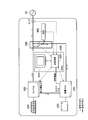
- FIG. 1 is a block diagram of a power control system according to the present embodiment.
- power lines are indicated by bold lines
- communication lines are indicated by broken lines.
- the communication line is not limited to a wired line and may be wireless.
- the power control system provides a solar cell (PV) 100, a PV power conditioner (PV PCS) to consumers who receive an alternating current (AC) power supply from the grid 10 of an electric power company. ) 150, storage battery 200, storage power conditioner (storage PCS) 250, distribution board 300, and one or more loads 400.
- PV solar cell
- PV PCS PV power conditioner
- AC alternating current
- the PV PCS 150 is equivalent to a grid interconnection device configured to perform a grid connection operation in which the output power of the PV 100 is input, and the PV 100 is linked to the grid 10 to supply power to the load 400. To do.
- PV100 receives sunlight and generates power, and outputs direct current (DC) power obtained by power generation to PV PCS150 via PV power line PL1 provided between PV100 and PVPCS150.
- DC direct current
- Storage battery 200 stores electric power.
- Storage battery 200 charges DC power from power storage PCS 250 via power storage power line PL ⁇ b> 2 provided between power storage PCS 250, converts the DC power generated by the discharge into AC power by power storage PCS 250, and distributes power to distribution board 300. Output.
- PV PCS150 converts DC power obtained by power generation of PV100 into AC and outputs it.
- the PV PCS 150 outputs AC power to the distribution board 300 via the PV interconnection output line PL3 provided between the PV PCS 150 and the distribution board 300 during the interconnection operation.
- the PV PCS 150 outputs AC power to the power storage PCS 250 through the PV self-sustained output line PL4 provided between the PV PCS 250 and the power storage PCS 250.
- the PV PCS 150 includes an inverter 151, a grid interconnection relay 152, an independent output relay 153, a PV controller 154, a sensor 155, and a sensor 156.
- the inverter 151 converts DC power output from the PV 100 into AC under the control of the PV controller 154.
- the grid interconnection relay 152 is turned on / off under the control of the PV controller 154.
- the grid interconnection relay 152 is on, the PV 100 is linked to the grid 10, and when the grid interconnection relay 152 is off, the PV 100 is disconnected from the grid 10.
- the interconnection operation is an operation state in which the grid interconnection relay 152 is on and the inverter 151 outputs AC power.
- the independent output relay 153 is turned on / off under the control of the PV controller 154. Independent operation is an operation state in which the independent output relay 153 is on and the inverter 151 outputs AC power.
- the grid interconnection relay 152 and the independent output relay 153 are controlled by the PV controller 154 so that only one of them is turned on.
- the PV controller 154 controls various functions of the PV PCS 150, and is configured using a processor and a memory.
- the PV controller 154 is configured to be able to communicate with the power storage PCS 250 via the communication line CL.
- the PV controller 154 and the power storage controller 253 detect a state where they can communicate with each other, and make a state where control described below can be performed.
- the PV controller 154 is not limited to a configuration that performs direct communication with the power storage controller 253, and may exchange information via a transceiver, a server, or a control device. Further, these pieces of information may be exchanged by wire or wireless.
- the PV controller 154 detects a state in which the output power amount of the PV PCS 150 is too small with respect to the power consumption amount of the load 400 during the interconnection operation, and turns off the grid interconnection relay 152 and stops the inverter 151. The system stop control is performed. In addition, when the PV controller 154 detects a state in which the output power of the PV 100 can be obtained after performing the interconnection stop control, the PV controller 154 performs activation control for starting the interconnection operation. The activation control will be described later.
- Sensor 155 is provided on PV power line PL 1, measures the output power state (voltage, current) of PV 100, and outputs the measurement result to PV controller 154.
- Sensor 156 is provided on PV self-supporting output line PL4, measures the output power state (voltage, current) of PV PCS 150, and outputs the measurement result to PV controller 154.
- the sensor 156 may not be provided.
- the storage PCS 250 converts AC power (mainly nighttime power) from the grid 10 or AC power from the PV PCS 150 into DC and outputs it to the storage battery 200 during charging.
- the power storage PCS 250 converts DC power obtained by discharging the storage battery 200 into AC, and distributes power through a power storage input / output line PL5 provided between the power distribution panel 300 and the power distribution PCS 250. It outputs to the board 300.
- the power storage PCS 250 includes a bidirectional converter 251, a grid interconnection relay 252, a power storage controller 253, and a sensor 254.
- the bidirectional converter 251 converts DC power output from the storage battery 200 into AC, or converts AC power from the system 10 or AC power from the PV PCS 150 into DC under the control of the storage controller 253.
- the grid interconnection relay 252 is turned on / off under the control of the power storage controller 253. When the grid interconnection relay 252 is in the on state, the storage battery 200 is linked to the grid 10, and when the grid interconnection relay 252 is in the off state, the storage battery 200 is disconnected from the grid 10.
- the power storage controller 253 controls various functions of the power storage PCS 250 and is configured using a processor and a memory.
- the power storage controller 253 is configured to be able to communicate with the PV controller 154 via the communication line CL.
- the power storage controller 253 performs a part of start-up control for starting the interconnection operation of the PV PCS 150 during the self-sustaining operation of the PV PCS 150. The activation control will be described later.
- the sensor 254 is provided on the PV independent output line PL4, measures the output power state (voltage, current) of the PV PCS 150, and outputs the measurement result to the PV controller 154.
- Distribution board 300 supplies AC power output from PV PCS 150 and AC power output from power storage PCS 250 to load 400.
- the distribution board 300 receives the shortage of AC power from the system 10 via the system power line PL7. Electricity) to supply to the load 400.
- the distribution board 300 reverses the excess AC power to the grid 10 via the grid power line PL7. Tidal current (power sale).
- the reverse power flow by the storage battery 200 power storage PCS 250
- the reverse power flow is limited to the output AC power of the PV PCS 150.
- the load 400 is supplied with AC power through the power supply line PL6 provided between the load 400 and the load 400, and operates by consuming the supplied AC power.
- the load 400 may be one or plural.
- the load 400 is not limited to lighting, or home appliances such as an air conditioner, a refrigerator, and a television, but may include a heat accumulator or the like.
- the activation control method according to the present embodiment controls activation of the PV PCS 150 configured to perform an interconnection operation in which the PV 100 is linked to the grid 10 and power is supplied to the load 400.
- the start-up control method first supplies power to the power storage PCS 250 from the self-sustained operation output of the PV PCS 150 by the self-sustaining operation that does not link the PV 100 to the grid 10 before starting the PV PCS 150 interconnected operation. Supply.
- the output power amount of the PV 100 or PV PCS 150 is measured.
- the independent operation is stopped and the interconnection operation is started.
- the activation control method uses the storage battery 200 as a predetermined load, and performs a test for confirming whether the output power amount of the PV 100 can be sufficiently obtained by the self-sustaining operation. And after confirming that the output electric energy of PV100 is fully obtained, the grid operation is started and power is supplied to the load 400, thereby preventing the PV PCS 150 from being started and stopped immediately.
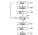
- FIG. 2 is a flowchart of the activation control method according to the present embodiment. This flow is performed, for example, at a timing (that is, early morning) when the amount of solar radiation with respect to PV 100 exceeds zero (that is, at night).
- a timing that is, early morning
- the self-sustained output relay 153 are in the off state, and the inverter 151 is stopped.
- step S101 the PV controller 154 detects a state in which the output power of the PV 100 can be obtained, and shifts to a start-up preparation state for starting the PV PCS 150 and starting the interconnection operation.
- step S102 the PV controller 154 turns on the self-sustained output relay 153 and starts the operation of the inverter 151, thereby starting the self-sustaining operation of the PV PCS 150.
- the AC power output from the inverter 151 is input to the bidirectional converter 251 of the power storage PCS 250 via the independent output relay 153 and the PV independent output line PL4.
- step S103 when the storage controller 253 detects that AC power is supplied via the PV self-supporting output line PL4, the storage controller 253 starts a charging mode for charging the storage battery 200.
- the power storage controller 253 performs control so that the charge amount of the storage battery 200 is gradually increased from zero.
- the charge amount is indicated by any one of current, voltage, power, current per unit time, or power.
- the PV controller 154 measures the output current value of the PV 100 when the output voltage value of the PV 100 gradually decreases, and measures the product of the output voltage value and the output current value of the PV 100 as the output power amount of the PV 100.
- step S104 the PV controller 154 determines whether to perform the interconnection operation of the PV PCS 150 based on the PV output power amount measured until the output voltage value of the PV 100 decreases by a certain value or more. Specifically, when the PV output power amount measured until the output voltage value of the PV 100 decreases by a certain value or more exceeds the start condition threshold (step S104; YES), it is determined that the PV PCS 150 is connected. Then, the process proceeds to step S105. On the other hand, when the PV output power amount is less than the activation condition threshold value (step S104; NO), it is determined that the PV PCS 150 is not currently connected, and the process returns to step S101.
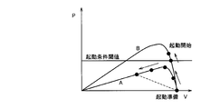
- FIG. 3 is a diagram showing a specific example of the relationship between the output voltage (V) and the output power (P) of the PV 100 (ie, the VP characteristic).
- V output voltage
- P output power
- the output power amount P of the PV 100 does not exceed the start condition threshold in the process of decreasing the output voltage value V of the PV 100.
- the PV controller 154 determines not to perform the interconnection operation of the PV PCS 150.
- the PV controller 154 determines to perform the interconnection operation of the PV PCS 150.
- step S105 the PV controller 154 stops the self-sustaining operation of the PV PCS 150 by turning off the self-sustaining output relay 153.
- step S106 the PV controller 154 shifts from the start preparation state to the start state.
- step S107 the PV controller 154 starts the interconnection operation by turning on the grid interconnection relay 152 while continuing the operation of the inverter 151.
- the PV PCS 150 supplies power to the power storage PCS 250 from the autonomous operation output of the PV PCS 150 by the independent operation that does not link the PV 100 to the grid 10 before starting the interconnection operation when the PV PCS 150 is started.
- Supplying means inverter 151, self-sustained output relay 153, power storage controller 253 to supply and stopping self-sustained operation when the output power amount of PV 100 when supplying power from self-sustained operation output to power storage PCS 250 is greater than a predetermined amount
- there are connected operation means inverter 151, system connection relay 152, PV controller 154) for starting the connected operation.
- the storage battery 200 has a variable charge amount and charges the power supplied from the PV PCS 150.
- the storage battery 200 having a variable charge amount as a predetermined load for the test, it is possible to check in stages how much the output power amount of the PV 100 can be drawn. And by charging without consuming the electric power obtained during such a test, the electric power can be prevented from being wasted.
- the PV controller 154 determines whether to start (start up) the PV PCS 150 based on the PV 100 output power amount. Based on this, it may be determined whether to start (start up) the interconnection operation of the PV PCS 150.
- the power control system according to the present embodiment is configured in the same manner as in the first embodiment, but the startup control method of the PV PCS 150 is partially different from that in the first embodiment.
- FIG. 4 is a flowchart of the activation control method according to this embodiment. In this flow, since steps other than steps S203 to S205 are the same as those in the first embodiment, steps S203 to S205 will be described.
- step S203 the power storage controller 253 starts a charging mode for charging the storage battery 200 when detecting that AC power is supplied via the PV self-sustained output line PL4.
- the power storage controller 253 performs control so that the charge amount of the storage battery 200 is gradually increased from zero.
- the output voltage value of the PV PCS 150 gradually decreases.
- the storage controller 253 measures the output current value of the PV PCS 150 when the output voltage value of the PV PCS 150 gradually decreases, and measures the product of the output voltage value and the output current value of the PV PCS 150 as the output power amount of the PV PCS 150 To do.
- step S ⁇ b> 204 the power storage controller 253 determines whether to perform the PV PCS 150 interconnection operation based on the PV PCS output power amount measured until the output voltage value of the PV PCS 150 decreases by a certain value or more. To do. Specifically, the storage controller 253, when the PV output power measured until the output voltage value of the PV PCS 150 drops by a certain value or more exceeds the start condition threshold (step S204; YES), It is determined that system operation is to be performed, a notification that the PV output power amount exceeds the activation condition threshold value is transmitted to the PV controller 154 via the communication line, and the process proceeds to step S205.
- step S204 when the PV PCS output power amount is less than the activation condition threshold (step S204; NO), the power storage controller 253 determines that the grid connection operation of the PV PCS 150 is not performed at this time, and the PV output power A notification that the amount is less than the activation condition threshold is transmitted to the PV controller 154 via the communication line, and the process returns to step S201.
- step S205 the PV controller 154 stops the independent operation of the PV PCS 150 by turning off the independent output relay 153 in response to the notification from the power storage controller 253. Thereafter, the PV controller 154 starts the interconnection operation in the same manner as in the first embodiment.
- FIG. 5 is a block diagram of the power control system according to the present embodiment.
- the power control system is different from the first embodiment and the second embodiment in that it includes a HEMS (Home Energy Management System) 600.
- the HEMS 600 performs power management within the consumer.
- the HEMS 600 collects various measurement values by transmitting various control commands to the PV PCS 150, the power storage PCS 250, and the load 400, and collects various measurement values to determine the state of each device in the consumer. It has a function to monitor and display.
- the HEMS 600 corresponds to a control device that controls the PV PCS 150 (system interconnection device).
- the HEMS 600 includes a HEMS controller 610 and a transceiver 620.
- the HEMS controller 610 is configured using a processor and a memory, and controls each device in the consumer using the transceiver 620.
- the transceiver 620 is configured to communicate with each device in the consumer.
- the HEMS 600 performs control for implementing the activation control method according to the first embodiment or the activation control method according to the second embodiment.
- step S101 the HEMS 600 detects a state in which the output power of the PV 100 can be obtained, and shifts to a startup preparation state for starting the PV PCS 150 and starting the interconnection operation.
- step S102 the HEMS 600 controls the PV PCS 150 so as to start the independent operation.
- the AC power output from the inverter 151 is input to the bidirectional converter 251 of the power storage PCS 250 via the independent output relay 153 and the PV independent output line PL4.
- step S103 when the HEMS 600 detects that AC power is supplied via the PV self-sustained output line PL4, the HEMS 600 controls the power storage PCS 250 to start a charging mode for charging the storage battery 200.
- the HEMS 600 controls the charging amount of the storage battery 200 to gradually increase from zero.
- the output voltage value of the PV 100 gradually decreases.
- the HEMS 600 measures the output current value of the PV 100 when the output voltage value of the PV 100 gradually decreases, and measures the product of the output voltage value and the output current value of the PV 100 as the output power amount of the PV 100.
- step S104 the HEMS 600 determines whether or not to perform the interconnection operation of the PV PCS 150 based on the PV output power amount measured until the output voltage value of the PV 100 decreases by a certain value or more. Specifically, when the PV output power amount measured until the output voltage value of the PV 100 decreases by a certain value or more exceeds the start condition threshold (step S104; YES), it is determined that the PV PCS 150 is connected. Then, the process proceeds to step S105. On the other hand, when the PV output power amount is less than the activation condition threshold value (step S104; NO), it is determined that the PV PCS 150 is not currently connected, and the process returns to step S101.
- step S105 the HEMS 600 controls the PV PCS 150 to stop the independent operation.
- step S106 the HEMS 600 shifts the PV PCS 150 from the start preparation state to the start state.
- step S107 the HEMS 600 controls the PV PCS 150 so as to start the interconnection operation.
- step S203 when the HEMS 600 detects that AC power is supplied via the PV self-sustained output line PL4, the HEMS 600 controls the power storage PCS 250 to start a charging mode for charging the storage battery 200. To do.
- the HEMS 600 controls the charging amount of the storage battery 200 to gradually increase from zero in the charging mode.
- the output voltage value of the PV PCS 150 gradually decreases.
- the HEMS 600 measures the output current value of the PV PCS 150 when the output voltage value of the PV PCS 150 gradually decreases, and measures the product of the output voltage value and the output current value of the PV PCS 150 as the output power amount of the PV PCS 150.
- step S204 the HEMS 600 determines whether or not to perform the interconnection operation of the PV PCS 150 based on the PV PCS output power amount measured until the output voltage value of the PV PCS 150 decreases by a certain value or more. Specifically, the HEMS 600 is connected to the PV PCS 150 when the PV output power measured before the output voltage value of the PV PCS 150 drops more than a certain value exceeds the start condition threshold (step S204; YES). The process proceeds to step S205. On the other hand, if the PV PCS output power amount is less than the activation condition threshold (step S204; NO), it is determined that the PV PCS 150 is not currently connected, and the process returns to step S201.
- step S205 the HEMS 600 controls the PV PCS 150 to stop the independent operation.
- the HEMS 600 stores power from the self-sustained operation output of the PV PCS 150 by the self-sustained operation that does not interconnect the PV 100 to the grid 10 before starting the interconnected operation when the PV PCS 150 is activated.
- Supply control means HEMS controller 610, transceiver 620
- HEMS controller 610, transceiver 620 for controlling power supply to PCS 250, and output power amount of PV 100 or PV PCS 150 when power is supplied to power storage PCS 250 from a self-sustained operation output is more than a predetermined amount
- it has an operation control means (HEMS controller 610, transceiver 620) which controls to stop the independent operation and start the interconnection operation.
- DC power may be supplied from the PV PCS 150 to the power storage PCS 250.
- a DC / DC converter (not shown) provided between the PV 100 and the inverter 151 is connected to the self-sustained output relay 153, and the self-sustained output relay 153, the storage battery 200, and the bidirectional converter 251 are connected. What is necessary is just to connect the DC / DC converter (not shown) provided between them by PV independent output line PL4.
- the storage battery 200 (and the storage PCS 250) is used as a predetermined load.
- a load with variable power consumption may be used instead of the storage battery 200 (and the storage PCS 250).
- the above-described control can be performed by changing the power consumption of the load manually or automatically.
- the present invention is useful in the electric power field because it can prevent the system interconnection device from being repeatedly started and stopped.
Landscapes
- Engineering & Computer Science (AREA)
- Power Engineering (AREA)
- Supply And Distribution Of Alternating Current (AREA)
- Charge And Discharge Circuits For Batteries Or The Like (AREA)
Abstract
PV100を系統10に連系して負荷400に電力を供給する連系運転を行うように構成されたPV PCS150の起動を制御する起動制御方法は、連系運転を開始する前に、PV100を系統10に連系しない自立運転によって、PV PCS150の自立運転出力から蓄電PCS250に電力を供給する。また、蓄電PCS250に電力が供給される際に、PV100又はPV PCS150の出力電力量を計測する。そして、計測された出力電力量が所定量よりも多い場合に、自立運転を停止して、連系運転を開始する。
Description
本発明は、太陽電池の出力電力が入力される系統連系装置の起動を制御する起動制御方法、系統連系装置、及び制御装置に関する。
近年、電力の需要家において、太陽光を受けて発電する太陽電池の普及が進んでいる。太陽電池の普及に伴い、太陽電池を商用電力系統(以下、「系統」)に連系して負荷に電力を供給する系統連系装置(いわゆる、パワーコンディショナ)の普及も進んでいる。
系統連系装置は、太陽電池を系統から解列するための系統連系リレーを有する(例えば、特許文献1参照)。
系統連系装置は、系統連系装置の出力電力量が負荷の消費電力量に対して過小である状態(例えば夜間など)を検知し、系統連系リレーをオフすることで太陽電池を系統から解列し、系統連系装置の運転を停止する連系停止制御を行うように構成されている。
また、系統連系装置は、太陽電池の出力電力が得られる状態を検知して、系統連系リレーをオンすることで太陽電池を系統に連系し、連系運転を開始する起動制御を行う。
しかしながら、系統連系装置の起動時に、早朝時又は曇天時といった超低日射状態であるなどの理由で、太陽電池の出力電力量が殆ど得られない場合、系統連系装置は、起動して直ぐに、上述した連系停止制御によって系統連系リレーをオフして停止する。そして、系統連系装置は、停止して直ぐに、上述した起動制御によって系統連系リレーをオンして再起動する。
その結果、系統連系装置の起動と停止、すなわち、系統連系リレーのオンとオフ(系統連系装置の起動と停止)が繰り返されてしまう問題がある。
そこで、本発明は、系統連系装置の起動と停止とが繰り返されることを防止できる起動制御方法、系統連系装置、及び制御装置を提供することを目的とする。
上述した課題を解決するために、本発明は以下のような特徴を有している。
本発明に係る起動制御方法の特徴は、太陽電池(PV100)の出力電力が入力され、前記太陽電池を系統(系統10)に連系して負荷(負荷400)に電力を供給する連系運転を行う、ように構成された系統連系装置(PV PCS150)の起動を制御する起動制御方法であって、前記連系運転を開始する前に、前記太陽電池を前記系統に連系しない自立運転によって、前記系統連系装置の自立運転出力から所定負荷(蓄電池200、蓄電PCS250)に電力を供給するステップAと、前記ステップAで前記所定負荷に電力が供給される際に、前記太陽電池又は前記系統連系装置の出力電力量を計測するステップBと、前記ステップBで計測された前記出力電力量が所定量よりも多い場合に、前記自立運転を停止して、前記連系運転を開始するステップCと、を有することを要旨とする。
このような特徴によれば、連系運転を開始する前に、自立運転を行うことによって、太陽電池の出力電力量(あるいは系統連系装置の出力電力量)が連系運転時にどの程度得られるのかを確認する試験を行うことができる。そして、太陽電池の出力電力量(あるいは系統連系装置の出力電力量)が十分に得られることを確認した上で、連系運転を開始することによって、系統連系装置が起動して直ぐに停止することがなくなるため、系統連系装置の起動と停止とが繰り返されることを防止できる。
本発明に係る起動制御方法の他の特徴は、上述した特徴において、前記所定負荷は、充電量が可変の蓄電池(蓄電池200)を含み、前記蓄電池が、前記ステップAで供給される電力を充電するステップDをさらに有することを要旨とする。
本発明に係る起動制御方法の他の特徴は、上述した特徴において、前記ステップBは、前記蓄電池の充電量を変化させながら、前記太陽電池又は前記系統連系装置の出力電力量を計測するステップB1を含むことを要旨とする。
本発明に係る起動制御方法の他の特徴は、上述した特徴において、前記所定負荷は、前記蓄電池と、前記蓄電池を前記系統に連系可能な他の系統連系装置(蓄電PCS250)と、を含み、前記系統連系装置の前記自立運転出力には、電力ライン(PV自立出力ラインPL4)を介して前記他の系統連系装置が接続され、前記ステップAは、前記自立運転出力から前記電力ラインを介して前記他の系統連系装置に交流電力を供給するステップA1を含むことを要旨とする。
本発明に係る系統連系装置の特徴は、太陽電池の出力電力が入力され、前記太陽電池を系統に連系して負荷に電力を供給する連系運転を行う、ように構成された系統連系装置であって、前記系統連系装置の起動時において、前記連系運転を開始する前に、前記太陽電池を前記系統に連系しない自立運転によって、前記系統連系装置の自立運転出力から所定負荷に電力を供給する供給部(インバータ151、自立出力リレー153、PVコントローラ154)と、前記自立運転出力から前記所定負荷に電力を供給する際の前記太陽電池又は前記系統連系装置の出力電力量が所定量よりも多い場合に、前記自立運転を停止して、前記連系運転を開始する連系運転部(インバータ151、系統連系リレー152、PVコントローラ154)と、を有することを要旨とする。
本発明に係る制御装置の特徴は、太陽電池の出力電力が入力され、前記太陽電池を系統に連系して負荷に電力を供給する連系運転を行う、ように構成された系統連系装置を制御する制御装置(HEMS600)であって、前記系統連系装置の起動時において、前記連系運転を開始する前に、前記太陽電池を前記系統に連系しない自立運転によって、前記系統連系装置の自立運転出力から所定負荷に電力を供給するよう制御する供給制御部(HEMSコントローラ610、送受信機620)と、前記自立運転出力から前記所定負荷に電力が供給される際の前記太陽電池又は前記系統連系装置の出力電力量が所定量よりも多い場合に、前記自立運転を停止して、前記連系運転を開始するよう制御する運転制御部(HEMSコントローラ610、送受信機620)と、を有することを要旨とする。
図面を参照して、本発明の第1実施形態~第3実施形態、及びその他の実施形態を説明する。以下の各実施形態における図面において、同一又は類似の部分には同一又は類似の符号を付す。
[第1実施形態]
図1は、本実施形態に係る電力制御システムのブロック図である。以下のブロック図において、電力ラインは太線で示し、通信ライン(信号ライン)は破線で示している。なお、通信ラインは有線に限らず無線であってもよい。
図1は、本実施形態に係る電力制御システムのブロック図である。以下のブロック図において、電力ラインは太線で示し、通信ライン(信号ライン)は破線で示している。なお、通信ラインは有線に限らず無線であってもよい。
図1に示すように、本実施形態に係る電力制御システムは、電力会社の系統10から交流(AC)電力の供給を受ける需要家に、太陽電池(PV)100、PVパワーコンディショナ(PV PCS)150、蓄電池200、蓄電パワーコンディショナ(蓄電PCS)250、分電盤300、1又は複数の負荷400が設けられる。
本実施形態において、PV PCS150は、PV100の出力電力が入力され、PV100を系統10に連系して負荷400に電力を供給する連系運転を行う、ように構成された系統連系装置に相当する。
PV100は、太陽光を受けて発電し、PV PCS150との間に設けられたPV電力ラインPL1を介して、発電により得られた直流(DC)電力をPV PCS150に出力する。
蓄電池200は、電力を蓄える。蓄電池200は、蓄電PCS250との間に設けられた蓄電電力ラインPL2を介して、蓄電PCS250からのDC電力を充電し、放電によるDC電力を蓄電PCS250でAC電力に変換して分電盤300に出力する。
PV PCS150は、PV100の発電により得られるDC電力をACに変換して出力する。PV PCS150は、連系運転時において、分電盤300との間に設けられたPV連系出力ラインPL3を介して、AC電力を分電盤300に出力する。これに対し、自立運転時において、PV PCS150は、蓄電PCS250との間に設けられたPV自立出力ラインPL4を介して、AC電力を蓄電PCS250に出力する。
PV PCS150は、インバータ151、系統連系リレー152、自立出力リレー153、PVコントローラ154、センサ155、センサ156を含む。
インバータ151は、PVコントローラ154の制御下で、PV100が出力するDC電力をACに変換する。
系統連系リレー152は、PVコントローラ154の制御下で、オン/オフする。系統連系リレー152がオン状態である場合には、PV100は系統10に連系され、系統連系リレー152がオフ状態である場合には、PV100は系統10から解列される。連系運転は、系統連系リレー152がオン状態であって、インバータ151がAC電力を出力する運転状態である。
自立出力リレー153は、PVコントローラ154の制御下で、オン/オフする。自立運転は、自立出力リレー153がオン状態であって、インバータ151がAC電力を出力する運転状態である。なお、系統連系リレー152及び自立出力リレー153は、PVコントローラ154によって、何れか一方のみがオン状態になるよう制御される。
PVコントローラ154は、PV PCS150の各種機能を制御するものであり、プロセッサやメモリを用いて構成される。PVコントローラ154は、通信ラインCLを介して蓄電PCS250と通信可能に構成される。PVコントローラ154及び蓄電コントローラ253は、相互に通信可能な状態を検知し、後述する制御を実施可能な状態にする。なお、PVコントローラ154は、蓄電コントローラ253との直接的な通信を行う構成に限らず、送受信機、サーバあるいは制御装置を介して情報をやり取りしてもよい。また、これら情報は、有線或いは無線によりやり取りされても良い。
PVコントローラ154は、連系運転時において、PV PCS150の出力電力量が負荷400の消費電力量に対して過小である状態を検知し、系統連系リレー152をオフするとともにインバータ151を停止させる連系停止制御を行うように構成されている。また、PVコントローラ154は、連系停止制御を行った後に、PV100の出力電力が得られる状態を検知すると、連系運転を開始するための起動制御を行う。起動制御については後述する。
センサ155は、PV電力ラインPL1上に設けられており、PV100の出力電力状態(電圧、電流)を測定し、測定結果をPVコントローラ154に出力する。
センサ156は、PV自立出力ラインPL4上に設けられており、PV PCS150の出力電力状態(電圧、電流)を測定し、測定結果をPVコントローラ154に出力する。ただし、本実施形態においては、センサ156は設けられていなくてもよい。
蓄電PCS250は、充電時には、系統10からのAC電力(主に夜間電力)や、PV PCS150からのAC電力をDCに変換して蓄電池200に出力する。これに対し、放電時には、蓄電PCS250は、蓄電池200の放電により得られるDC電力をACに変換して、分電盤300との間に設けられた蓄電連系入出力ラインPL5を介して分電盤300に出力する。
蓄電PCS250は、双方向コンバータ251、系統連系リレー252、蓄電コントローラ253、センサ254を含む。
双方向コンバータ251は、蓄電コントローラ253の制御下で、蓄電池200が出力するDC電力をACに変換したり、系統10からのAC電力やPV PCS150からのAC電力をDCに変換したりする。
系統連系リレー252は、蓄電コントローラ253の制御下で、オン/オフする。系統連系リレー252がオン状態である場合には、蓄電池200は系統10に連系され、系統連系リレー252がオフ状態である場合には、蓄電池200は系統10から解列される。
蓄電コントローラ253は、蓄電PCS250の各種機能を制御するものであり、プロセッサやメモリを用いて構成される。蓄電コントローラ253は、通信ラインCLを介してPVコントローラ154と通信可能に構成される。蓄電コントローラ253は、PV PCS150の自立運転時に、PV PCS150の連系運転を開始するための起動制御の一部を行う。起動制御については後述する。
センサ254は、PV自立出力ラインPL4上に設けられており、PV PCS150の出力電力状態(電圧、電流)を測定し、測定結果をPVコントローラ154に出力する。
分電盤300は、PV PCS150が出力するAC電力及び蓄電PCS250が出力するAC電力を負荷400に供給する。分電盤300は、PV PCS150及び蓄電PCS250の総出力AC電力量が負荷400の消費電力量未満である場合には、不足分のAC電力を系統電力ラインPL7を介して系統10から受電(買電)して負荷400に供給する。また、分電盤300は、PV PCS150及び蓄電PCS250の総出力AC電力量が負荷400の消費電力量よりも多い場合には、超過分のAC電力を系統電力ラインPL7を介して系統10に逆潮流(売電)する。なお、蓄電池200(蓄電PCS250)による逆潮流は認められていないため、逆潮流されるのはPV PCS150の出力AC電力に限られる。
負荷400は、分電盤300との間に設けられた電力供給ラインPL6を介してAC電力が供給され、供給されたAC電力を消費して動作する。負荷400は、1つであってもよく、複数であってもよい。負荷400には、照明、あるいはエアコンや冷蔵庫、テレビ等の家電機器に限らず、蓄熱器等が含まれていることがある。
次に、本実施形態に係るPV PCS150の起動制御方法を説明する。
ここで、本実施形態に係る起動制御方法の概要を説明する。本実施形態に係る起動制御方法は、PV100を系統10に連系して負荷400に電力を供給する連系運転を行うように構成されたPV PCS150の起動を制御するものである。
本実施形態に係る起動制御方法は、第1に、PV PCS150の連系運転を開始する前に、PV100を系統10に連系しない自立運転によって、PV PCS150の自立運転出力から蓄電PCS250に電力を供給する。第2に、PV PCS150から蓄電PCS250に電力が供給される際に、PV100又はPV PCS150の出力電力量を計測する。第3に、計測された出力電力量が所定量よりも多い場合に、自立運転を停止して、連系運転を開始する。
このように、本実施形態に係る起動制御方法は、蓄電池200を所定負荷として使用して、自立運転によって、PV100の出力電力量が十分に得られるかを確認するための試験を行う。そして、PV100の出力電力量が十分に得られることを確認した上で、連系運転を開始して負荷400に電力を供給することによって、PV PCS150が起動して直ぐに停止することを防止する。
図2は、本実施形態に係る起動制御方法のフロー図である。本フローは、例えば、PV100に対する日射量がゼロの状態(すなわち、夜間)からゼロを超えたタイミング(すなわち、早朝)で行われる。本フローの開始時点では、PV PCS150において、系統連系リレー152及び自立出力リレー153の何れもオフ状態であり、且つインバータ151が停止している状態である。
図2に示すように、ステップS101において、PVコントローラ154は、PV100の出力電力が得られる状態を検知し、PV PCS150を起動して連系運転を開始するための起動準備状態に移行する。
ステップS102において、PVコントローラ154は、自立出力リレー153をオンし、インバータ151の運転を開始することによって、PV PCS150の自立運転を開始する。その結果、インバータ151が出力するAC電力が自立出力リレー153及びPV自立出力ラインPL4を介して蓄電PCS250の双方向コンバータ251に入力される。
ステップS103において、蓄電コントローラ253は、PV自立出力ラインPL4を介してAC電力が供給されたことを検知すると、蓄電池200を充電するための充電モードを開始する。蓄電コントローラ253は、充電モードにおいては、蓄電池200の充電量をゼロから徐々に増加するよう制御する。なお、充電量は、電流、電圧、電力、単位時間当たりの電流または電力の何れかで示される。
蓄電池200の充電量をゼロから段階的に増加すると、PV100の出力電圧値が徐々に低下する。PVコントローラ154は、PV100の出力電圧値が徐々に低下する際のPV100の出力電流値を測定するとともに、PV100の出力電圧値及び出力電流値の積をPV100の出力電力量として計測する。
そして、ステップS104において、PVコントローラ154は、PV100の出力電圧値がある値以上低下するまでに計測されるPV出力電力量に基づいて、PV PCS150の連系運転を行うか否かを判断する。詳細には、PV100の出力電圧値がある値以上低下するまでに計測されるPV出力電力量が起動条件閾値を超える場合(ステップS104;YES)には、PV PCS150の連系運転を行うと判断し、処理をステップS105に進める。これに対し、当該PV出力電力量が起動条件閾値未満である場合(ステップS104;NO)には、PV PCS150の連系運転を現時点では行わないと判断し、処理をステップS101に戻す。
図3は、PV100の出力電圧(V)及び出力電力(P)の関係(すなわち、V-P特性)の具体例を示す図である。図3における“A”はPV100で日射量が殆ど得られていない場合のPV100のV-P特性であり、“B”はPV100で日射量がある程度は得られている場合のPV100のV-P特性である。
図3に示すように、V-P特性“A”では、PV100の出力電圧値Vが低下していく課程で、PV100の出力電力量Pは起動条件閾値を超えない。このような場合、PVコントローラ154は、PV PCS150の連系運転を行わないと判断する。
一方、V-P特性“B”では、PV100の出力電圧値Vが低下していく課程で、PV100の出力電力量Pが起動条件閾値を超える。このような場合、PVコントローラ154は、PV PCS150の連系運転を行うと判断する。
ステップS105において、PVコントローラ154は、自立出力リレー153をオフすることによって、PV PCS150の自立運転を停止する。
ステップS106において、PVコントローラ154は、起動準備状態から起動状態に移行する。
ステップS107において、PVコントローラ154は、インバータ151の運転を継続しつつ、系統連系リレー152をオンすることによって、連系運転を開始する。
以上説明したように、PV PCS150は、PV PCS150の起動時において、連系運転を開始する前に、PV100を系統10に連系しない自立運転によって、PV PCS150の自立運転出力から蓄電PCS250に電力を供給する供給手段(インバータ151、自立出力リレー153、蓄電コントローラ253)と、自立運転出力から蓄電PCS250に電力を供給する際のPV100の出力電力量が所定量よりも多い場合に、自立運転を停止して、連系運転を開始する連系運転手段(インバータ151、系統連系リレー152、PVコントローラ154)と、を有する。
このように、連系運転を開始する前に、自立運転を行うことによって、PV100の出力電力量が連系運転時にどの程度得られるのかを確認する試験を行うことができる。そして、PV100の出力電力量が十分に得られることを確認した上で、連系運転を開始することによって、PV PCS150が起動して直ぐに停止することがなくなるため、PV PCS150の起動と停止とが繰り返されることを防止できる。
本実施形態では、蓄電池200は、充電量が可変であり、PV PCS150から供給される電力を充電する。このように、試験のための所定負荷として、充電量が可変の蓄電池200を使用することで、PV100の出力電力量をどの程度引き出せるのかを段階的に確認することができる。そして、そのような試験中に得られる電力を消費せずに充電することによって、当該電力を無駄にしないようにすることができる。
なお、本実施形態においては、PVコントローラ154が、PV100の出力電力量に基づいてPV PCS150の連系運転を開始(起動)するか否かを決定していたが、PV PCS150の出力電力量に基づいてPV PCS150の連系運転を開始(起動)するか否かを決定してもよい。
[第2実施形態]
以下、第2実施形態について、第1実施形態との相違点を説明する。
以下、第2実施形態について、第1実施形態との相違点を説明する。
本実施形態に係る電力制御システムは、第1実施形態と同様に構成されるが、PV PCS150の起動制御方法が第1実施形態とは一部異なる。
図4は、本実施形態に係る起動制御方法のフロー図である。本フローは、ステップS203~S205以外の各ステップは第1実施形態と同様であるため、ステップS203~S205について説明する。
図4に示すように、ステップS203において、蓄電コントローラ253は、PV自立出力ラインPL4を介してAC電力が供給されたことを検知すると、蓄電池200を充電するための充電モードを開始する。蓄電コントローラ253は、充電モードにおいては、蓄電池200の充電量をゼロから徐々に増加するよう制御する。蓄電池200の充電量をゼロから段階的に増加すると、PV PCS150の出力電圧値が徐々に低下する。蓄電コントローラ253は、PV PCS150の出力電圧値が徐々に低下する際のPV PCS150の出力電流値を測定するとともに、PV PCS150の出力電圧値及び出力電流値の積をPV PCS150の出力電力量として計測する。
そして、ステップS204において、蓄電コントローラ253は、PV PCS150の出力電圧値がある値以上低下するまでに計測されるPV PCS出力電力量に基づいて、PV PCS150の連系運転を行うか否かを判断する。詳細には、蓄電コントローラ253は、PV PCS150の出力電圧値がある値以上低下するまでに計測されるPV出力電力量が起動条件閾値を超える場合(ステップS204;YES)には、PV PCS150の連系運転を行うと判断し、PV出力電力量が起動条件閾値を超える旨の通知を通信ラインを介してPVコントローラ154に送信し、処理をステップS205に進める。これに対し、当該PV PCS出力電力量が起動条件閾値未満である場合(ステップS204;NO)には、蓄電コントローラ253は、PV PCS150の連系運転を現時点では行わないと判断し、PV出力電力量が起動条件閾値未満である旨の通知を通信ラインを介してPVコントローラ154に送信し、処理をステップS201に戻す。
ステップS205において、PVコントローラ154は、蓄電コントローラ253からの通知に応じて、自立出力リレー153をオフすることによって、PV PCS150の自立運転を停止する。以降は、PVコントローラ154は、第1実施形態と同様にして連系運転を開始する。
以上説明したように、連系運転を開始する前に、自立運転を行うことによって、PV PCS150の出力電力量が連系運転時にどの程度得られるのかを確認する試験を行うことができる。そして、PV PCS150の出力電力量が十分に得られることを確認した上で、連系運転を開始することによって、PV PCS150が起動して直ぐに停止することがなくなるため、PV PCS150の起動と停止とが繰り返されることを防止できる。
[第3実施形態]
以下、第3実施形態について、第1実施形態及び第2実施形態との相違点を説明する。図5は、本実施形態に係る電力制御システムのブロック図である。
以下、第3実施形態について、第1実施形態及び第2実施形態との相違点を説明する。図5は、本実施形態に係る電力制御システムのブロック図である。
図5に示すように、本実施形態に係る電力制御システムは、HEMS(Home Energy Management System)600を有する点で第1実施形態及び第2実施形態とは異なる。HEMS600は、需要家内の電力管理を行う。HEMS600は、PV PCS150や蓄電PCS250、負荷400に対して各種の制御コマンドを送信することにより需要家内の各機器を制御する機能と、各種の計測値を収集して需要家内の各機器の状態を監視・表示する機能とを有する。本実施形態において、HEMS600は、PV PCS150(系統連系装置)を制御する制御装置に相当する。
HEMS600は、HEMSコントローラ610及び送受信機620を含む。HEMSコントローラ610は、プロセッサやメモリを用いて構成され、送受信機620を用いて需要家内の各機器を制御する。送受信機620は、需要家内の各機器との通信を行うように構成される。
このように構成された電力供給システムにおいて、HEMS600は、第1実施形態に係る起動制御方法又は第2実施形態に係る起動制御方法を実施するための制御を行う。
まず、HEMS600が、第1実施形態に係る起動制御方法を実施するための制御を行う場合の動作について、図2のフロー図を用いて説明する。
図2に示すように、ステップS101において、HEMS600は、PV100の出力電力が得られる状態を検知し、PV PCS150を起動して連系運転を開始するための起動準備状態に移行する。
ステップS102において、HEMS600は、自立運転を開始するようPV PCS150を制御する。その結果、インバータ151が出力するAC電力が自立出力リレー153及びPV自立出力ラインPL4を介して蓄電PCS250の双方向コンバータ251に入力される。
ステップS103において、HEMS600は、PV自立出力ラインPL4を介してAC電力が供給されたことを検知すると、蓄電池200を充電するための充電モードを開始するよう蓄電PCS250を制御する。HEMS600は、充電モードにおいては、蓄電池200の充電量をゼロから徐々に増加するよう制御する。蓄電池200の充電量をゼロから段階的に増加すると、PV100の出力電圧値が徐々に低下する。HEMS600は、PV100の出力電圧値が徐々に低下する際のPV100の出力電流値を測定するとともに、PV100の出力電圧値及び出力電流値の積をPV100の出力電力量として計測する。
そして、ステップS104において、HEMS600は、PV100の出力電圧値がある値以上低下するまでに計測されるPV出力電力量に基づいて、PV PCS150の連系運転を行うか否かを判断する。詳細には、PV100の出力電圧値がある値以上低下するまでに計測されるPV出力電力量が起動条件閾値を超える場合(ステップS104;YES)には、PV PCS150の連系運転を行うと判断し、処理をステップS105に進める。これに対し、当該PV出力電力量が起動条件閾値未満である場合(ステップS104;NO)には、PV PCS150の連系運転を現時点では行わないと判断し、処理をステップS101に戻す。
ステップS105において、HEMS600は、自立運転を停止するようPV PCS150を制御する。
ステップS106において、HEMS600は、PV PCS150を起動準備状態から起動状態に移行する。
ステップS107において、HEMS600は、連系運転を開始するようPV PCS150を制御する。
次に、HEMS600が、第2実施形態に係る起動制御方法を実施するための制御を行う場合の動作について、図4のフロー図を用いて説明する。ただし、第1実施形態に係る起動制御方法を実施するための制御を行う場合の動作と重複する動作については説明を省略する。
図4に示すように、ステップS203において、HEMS600は、PV自立出力ラインPL4を介してAC電力が供給されたことを検知すると、蓄電池200を充電するための充電モードを開始するよう蓄電PCS250を制御する。HEMS600は、充電モードにおいて、蓄電池200の充電量をゼロから徐々に増加するよう制御する。蓄電池200の充電量をゼロから段階的に増加すると、PV PCS150の出力電圧値が徐々に低下する。HEMS600は、PV PCS150の出力電圧値が徐々に低下する際のPV PCS150の出力電流値を測定するとともに、PV PCS150の出力電圧値及び出力電流値の積をPV PCS150の出力電力量として計測する。
そして、ステップS204において、HEMS600は、PV PCS150の出力電圧値がある値以上低下するまでに計測されるPV PCS出力電力量に基づいて、PV PCS150の連系運転を行うか否かを判断する。詳細には、HEMS600は、PV PCS150の出力電圧値がある値以上低下するまでに計測されるPV出力電力量が起動条件閾値を超える場合(ステップS204;YES)には、PV PCS150の連系運転を行うと判断し、処理をステップS205に進める。これに対し、当該PV PCS出力電力量が起動条件閾値未満である場合(ステップS204;NO)には、PV PCS150の連系運転を現時点では行わないと判断し、処理をステップS201に戻す。
ステップS205において、HEMS600は、自立運転を停止するようPV PCS150を制御する。
以上説明したように、本実施形態に係るHEMS600は、PV PCS150の起動時において、連系運転を開始する前に、PV100を系統10に連系しない自立運転によって、PV PCS150の自立運転出力から蓄電PCS250に電力を供給するよう制御する供給制御手段(HEMSコントローラ610、送受信機620)と、自立運転出力から蓄電PCS250に電力が供給される際のPV100又はPV PCS150の出力電力量が所定量よりも多い場合に、自立運転を停止して、連系運転を開始するよう制御する運転制御手段(HEMSコントローラ610、送受信機620)と、を有する。これにより、PV PCS150と蓄電PCS250との間に通信ラインが設けられない構成においても、第1実施形態及び第2実施形態に係る起動制御方法を実施できる。
[その他の実施形態]
上記のように、本発明は各実施形態によって記載したが、この開示の一部をなす論述及び図面はこの発明を限定するものであると理解すべきではない。この開示から当業者には様々な代替実施形態、実施例及び運用技術が明らかとなる。
上記のように、本発明は各実施形態によって記載したが、この開示の一部をなす論述及び図面はこの発明を限定するものであると理解すべきではない。この開示から当業者には様々な代替実施形態、実施例及び運用技術が明らかとなる。
上述した各実施形態においては、蓄電池200の充電量をゼロから徐々に増加させる一例を説明したが、前日の起動時(連系運転開始時)のPV出力電力量又はPV PCS出力電力量を学習しておき、そのポイントから動作させてもよい。これにより、起動判定に要する時間を短縮できる。また、蓄電池200の充電量をゼロから徐々に増加させる、すなわち、PV出力電圧を徐々に減少させるのは、PV100のV-P特性(V-Pカーブ)の形状を考慮したものであるが、これとは逆に、蓄電池200の充電量を最大値から徐々に減少させる、すなわち、PV出力電圧を徐々に増加させるようにしてもよい。
上述した各実施形態では、PV PCS150から蓄電PCS250にAC電力を供給する一例を説明したが、PV PCS150から蓄電PCS250にDC電力を供給する構成としてもよい。この場合、図1において、PV100とインバータ151との間に設けられるDC/DCコンバータ(不図示)を自立出力リレー153に接続し、当該自立出力リレー153と、蓄電池200と双方向コンバータ251との間に設けられるDC/DCコンバータ(不図示)と、をPV自立出力ラインPL4で接続すればよい。
さらに、上述した各実施形態では、PV PCS150と蓄電PCS250とを個別に設ける一例を説明したが、蓄電PCS250をPV PCS150と一体化する構成(いわゆる、ハイブリッドPCS)でもよい。
上述した各実施形態では、蓄電池200(及び蓄電PCS250)を所定負荷として使用していたが、蓄電池200(及び蓄電PCS250)に代えて、消費電力量が可変の負荷などを使用してもよい。この場合、当該負荷の消費電力量を手動又は自動で変更することで、上述した制御を実施可能である。
なお、日本国特許出願第2011-161246号(2011年7月22日出願)の全内容が、参照により、本願明細書に組み込まれている。
以上のように、本発明は、系統連系装置の起動と停止とが繰り返されることを防止できるので、電力分野において有用である。
Claims (6)
- 太陽電池の出力電力が入力され、前記太陽電池を系統に連系して負荷に電力を供給する連系運転を行う、ように構成された系統連系装置の起動を制御する起動制御方法であって、
前記連系運転を開始する前に、前記太陽電池を前記系統に連系しない自立運転によって、前記系統連系装置の自立運転出力から所定負荷に電力を供給するステップAと、
前記ステップAで前記所定負荷に電力が供給される際に、前記太陽電池又は前記系統連系装置の出力電力量を計測するステップBと、
前記ステップBで計測された前記出力電力量が所定量よりも多い場合に、前記自立運転を停止して、前記連系運転を開始するステップCと、
を有することを特徴とする起動制御方法。 - 前記所定負荷は、充電量が可変の蓄電池を含み、
前記蓄電池が、前記ステップAで供給される電力を充電するステップDをさらに有することを特徴とする請求項1に記載の起動制御方法。 - 前記ステップBは、前記蓄電池の充電量を変化させながら、前記太陽電池又は前記系統連系装置の出力電力量を計測するステップB1を含むことを特徴とする請求項2に記載の起動制御方法。
- 前記所定負荷は、
前記蓄電池と、
前記蓄電池を前記系統に連系可能な他の系統連系装置と、を含み、
前記系統連系装置の前記自立運転出力には、電力ラインを介して前記他の系統連系装置が接続され、
前記ステップAは、前記自立運転出力から前記電力ラインを介して前記他の系統連系装置に交流電力を供給するステップA1を含むことを特徴とする請求項2に記載の起動制御方法。 - 太陽電池の出力電力が入力され、前記太陽電池を系統に連系して負荷に電力を供給する連系運転を行う、ように構成された系統連系装置であって、
前記系統連系装置の起動時において、前記連系運転を開始する前に、前記太陽電池を前記系統に連系しない自立運転によって、前記系統連系装置の自立運転出力から所定負荷に電力を供給する供給部と、
前記自立運転出力から前記所定負荷に電力を供給する際の前記太陽電池又は前記系統連系装置の出力電力量が所定量よりも多い場合に、前記自立運転を停止して、前記連系運転を開始する連系運転部と、
を有することを特徴とする系統連系装置。 - 太陽電池の出力電力が入力され、前記太陽電池を系統に連系して負荷に電力を供給する連系運転を行う、ように構成された系統連系装置を制御する制御装置であって、
前記系統連系装置の起動時において、前記連系運転を開始する前に、前記太陽電池を前記系統に連系しない自立運転によって、前記系統連系装置の自立運転出力から所定負荷に電力を供給するよう制御する供給制御部と、
前記自立運転出力から前記所定負荷に電力が供給される際の前記太陽電池又は前記系統連系装置の出力電力量が所定量よりも多い場合に、前記自立運転を停止して、前記連系運転を開始するよう制御する運転制御部と、
を有することを特徴とする制御装置。
Priority Applications (3)
| Application Number | Priority Date | Filing Date | Title |
|---|---|---|---|
| EP12818172.4A EP2736143B1 (en) | 2011-07-22 | 2012-07-19 | Startup control method, grid-connected device, and control device |
| US14/234,332 US9705328B2 (en) | 2011-07-22 | 2012-07-19 | Startup control method, grid interconnection apparatus, and controller |
| CN201280036145.6A CN103718415B (zh) | 2011-07-22 | 2012-07-19 | 启动控制方法、系统互连装置和控制装置 |
Applications Claiming Priority (2)
| Application Number | Priority Date | Filing Date | Title |
|---|---|---|---|
| JP2011-161246 | 2011-07-22 | ||
| JP2011161246A JP5719714B2 (ja) | 2011-07-22 | 2011-07-22 | 起動制御方法、系統連系装置、及び制御装置 |
Publications (1)
| Publication Number | Publication Date |
|---|---|
| WO2013015191A1 true WO2013015191A1 (ja) | 2013-01-31 |
Family
ID=47601039
Family Applications (1)
| Application Number | Title | Priority Date | Filing Date |
|---|---|---|---|
| PCT/JP2012/068326 Ceased WO2013015191A1 (ja) | 2011-07-22 | 2012-07-19 | 起動制御方法、系統連系装置、及び制御装置 |
Country Status (5)
| Country | Link |
|---|---|
| US (1) | US9705328B2 (ja) |
| EP (1) | EP2736143B1 (ja) |
| JP (1) | JP5719714B2 (ja) |
| CN (1) | CN103718415B (ja) |
| WO (1) | WO2013015191A1 (ja) |
Cited By (2)
| Publication number | Priority date | Publication date | Assignee | Title |
|---|---|---|---|---|
| CN103227560A (zh) * | 2013-03-28 | 2013-07-31 | 华为技术有限公司 | 启动逆变器的方法和装置 |
| CN109691230A (zh) * | 2016-07-22 | 2019-04-26 | 卢特龙电子公司 | 模块化照明面板 |
Families Citing this family (10)
| Publication number | Priority date | Publication date | Assignee | Title |
|---|---|---|---|---|
| WO2013001820A1 (ja) * | 2011-06-28 | 2013-01-03 | 京セラ株式会社 | 系統連系インバータ装置およびその制御方法 |
| JP5777965B2 (ja) * | 2011-07-22 | 2015-09-16 | 京セラ株式会社 | 故障診断方法、系統連系装置、及び制御装置 |
| JP5798594B2 (ja) | 2013-06-18 | 2015-10-21 | トヨタ自動車株式会社 | 充電制御装置 |
| JP6297945B2 (ja) * | 2014-08-07 | 2018-03-20 | 田淵電機株式会社 | 太陽光発電システムの複合検査装置 |
| KR20160044353A (ko) | 2014-10-15 | 2016-04-25 | 엘에스산전 주식회사 | 계통 연계형 태양광 발전 시스템 |
| JP2016103900A (ja) * | 2014-11-28 | 2016-06-02 | 株式会社日立製作所 | 蓄電池システム |
| GB201515732D0 (en) * | 2014-12-12 | 2015-10-21 | Hickson Ian | Electrical power control device and system |
| JP6480198B2 (ja) * | 2015-01-28 | 2019-03-06 | 株式会社日立製作所 | 蓄電池システム及びそれを有する太陽光発電システム |
| CN113691131B (zh) * | 2021-06-23 | 2024-03-26 | 天津工业大学 | 一种宽输入范围三端口变换器控制方法 |
| SE546924C2 (en) * | 2023-03-06 | 2025-03-11 | Blixt Tech Ab | Electrical coupling system |
Citations (3)
| Publication number | Priority date | Publication date | Assignee | Title |
|---|---|---|---|---|
| JPH01243826A (ja) * | 1988-03-19 | 1989-09-28 | Sanyo Electric Co Ltd | 系統連系太陽光発電システムの起動方法 |
| JP2000350468A (ja) | 1999-06-02 | 2000-12-15 | Matsushita Electric Ind Co Ltd | 系統連系インバータ |
| JP2010130836A (ja) * | 2008-11-28 | 2010-06-10 | Seiko Electric Co Ltd | 電力供給システム及び電力切替装置 |
Family Cites Families (10)
| Publication number | Priority date | Publication date | Assignee | Title |
|---|---|---|---|---|
| JPH08191573A (ja) * | 1995-01-10 | 1996-07-23 | Sanyo Electric Co Ltd | 太陽光発電装置 |
| JP3451945B2 (ja) * | 1998-06-30 | 2003-09-29 | 松下電工株式会社 | 太陽光発電インバータ装置 |
| JP4213941B2 (ja) * | 2002-10-11 | 2009-01-28 | シャープ株式会社 | 複数の分散電源の出力抑制方法および分散電源管理システム |
| CN101765959B (zh) * | 2007-05-08 | 2015-04-15 | 美国电力转换有限公司 | 交流电源能量管理 |
| CN201270420Y (zh) * | 2008-09-22 | 2009-07-08 | 珠海赛比特电气设备有限公司 | 一种光伏并网逆变器的启动电路 |
| JP5531473B2 (ja) * | 2009-07-07 | 2014-06-25 | 富士通モバイルコミュニケーションズ株式会社 | 情報処理装置 |
| KR101097260B1 (ko) * | 2009-12-15 | 2011-12-22 | 삼성에스디아이 주식회사 | 계통 연계형 전력 저장 시스템 및 전력 저장 시스템 제어 방법 |
| CN101826821B (zh) * | 2010-02-08 | 2012-06-27 | 哈尔滨工业大学 | 光网混合供电不间断逆变电源的电能控制方法 |
| ES2777887T3 (es) * | 2010-05-03 | 2020-08-06 | Siemens Gamesa Renewable Energy As | Sistema para intercambiar energía eléctrica entre una batería y una red eléctrica y procedimiento respectivo |
| KR101174891B1 (ko) * | 2010-06-01 | 2012-08-17 | 삼성에스디아이 주식회사 | 전력 저장 시스템 및 그 제어방법 |
-
2011
- 2011-07-22 JP JP2011161246A patent/JP5719714B2/ja active Active
-
2012
- 2012-07-19 EP EP12818172.4A patent/EP2736143B1/en not_active Not-in-force
- 2012-07-19 WO PCT/JP2012/068326 patent/WO2013015191A1/ja not_active Ceased
- 2012-07-19 US US14/234,332 patent/US9705328B2/en active Active
- 2012-07-19 CN CN201280036145.6A patent/CN103718415B/zh active Active
Patent Citations (3)
| Publication number | Priority date | Publication date | Assignee | Title |
|---|---|---|---|---|
| JPH01243826A (ja) * | 1988-03-19 | 1989-09-28 | Sanyo Electric Co Ltd | 系統連系太陽光発電システムの起動方法 |
| JP2000350468A (ja) | 1999-06-02 | 2000-12-15 | Matsushita Electric Ind Co Ltd | 系統連系インバータ |
| JP2010130836A (ja) * | 2008-11-28 | 2010-06-10 | Seiko Electric Co Ltd | 電力供給システム及び電力切替装置 |
Non-Patent Citations (1)
| Title |
|---|
| See also references of EP2736143A4 |
Cited By (3)
| Publication number | Priority date | Publication date | Assignee | Title |
|---|---|---|---|---|
| CN103227560A (zh) * | 2013-03-28 | 2013-07-31 | 华为技术有限公司 | 启动逆变器的方法和装置 |
| CN109691230A (zh) * | 2016-07-22 | 2019-04-26 | 卢特龙电子公司 | 模块化照明面板 |
| CN109691230B (zh) * | 2016-07-22 | 2021-09-03 | 路创技术有限责任公司 | 模块化照明面板 |
Also Published As
| Publication number | Publication date |
|---|---|
| CN103718415B (zh) | 2016-08-17 |
| JP2013027208A (ja) | 2013-02-04 |
| US20140152101A1 (en) | 2014-06-05 |
| EP2736143A1 (en) | 2014-05-28 |
| JP5719714B2 (ja) | 2015-05-20 |
| CN103718415A (zh) | 2014-04-09 |
| US9705328B2 (en) | 2017-07-11 |
| EP2736143B1 (en) | 2017-04-26 |
| EP2736143A4 (en) | 2015-07-29 |
Similar Documents
| Publication | Publication Date | Title |
|---|---|---|
| JP5719714B2 (ja) | 起動制御方法、系統連系装置、及び制御装置 | |
| JP5777965B2 (ja) | 故障診断方法、系統連系装置、及び制御装置 | |
| US10243396B2 (en) | Control device, power control system, and power control method | |
| US9651971B2 (en) | Control device, power control system, and power control method | |
| US9876391B2 (en) | Power conversion apparatus, control system, and control method | |
| KR20160001249A (ko) | 태양광 발전과 에너지 저장 시스템을 이용한 홈 에너지 관리 시스템 | |
| JP2011250673A (ja) | エネルギーコントローラおよび制御方法 | |
| US9846418B2 (en) | Energy control system, energy control device, and energy control method for prioritizing a power generation source based on the possibility of selling generated power | |
| JP5373528B2 (ja) | 配電装置 | |
| WO2013047840A1 (ja) | 電力管理システム、電力管理装置及び電力管理方法 | |
| JP2013247838A (ja) | 電力制御方法、電力制御システム、及び制御装置 | |
| JP2018207786A (ja) | 電力制御システムの制御方法、電力制御システム、及び電力制御装置 | |
| WO2016136911A1 (ja) | 電力変換装置及び電力変換方法 | |
| JP2016086594A (ja) | 電力供給システム、電力供給機器及び電力供給システムの制御方法 | |
| WO2012046381A1 (ja) | 発電システム及び発電システムの運転方法 | |
| WO2013047843A1 (ja) | エネルギー管理システム、エネルギー管理装置及び電力管理方法 |
Legal Events
| Date | Code | Title | Description |
|---|---|---|---|
| 121 | Ep: the epo has been informed by wipo that ep was designated in this application |
Ref document number: 12818172 Country of ref document: EP Kind code of ref document: A1 |
|
| NENP | Non-entry into the national phase |
Ref country code: DE |
|
| WWE | Wipo information: entry into national phase |
Ref document number: 14234332 Country of ref document: US |
|
| REEP | Request for entry into the european phase |
Ref document number: 2012818172 Country of ref document: EP |
|
| WWE | Wipo information: entry into national phase |
Ref document number: 2012818172 Country of ref document: EP |