WO2013015273A1 - 電池システム - Google Patents
電池システム Download PDFInfo
- Publication number
- WO2013015273A1 WO2013015273A1 PCT/JP2012/068691 JP2012068691W WO2013015273A1 WO 2013015273 A1 WO2013015273 A1 WO 2013015273A1 JP 2012068691 W JP2012068691 W JP 2012068691W WO 2013015273 A1 WO2013015273 A1 WO 2013015273A1
- Authority
- WO
- WIPO (PCT)
- Prior art keywords
- power
- battery
- unit
- supplied
- battery units
- Prior art date
- Legal status (The legal status is an assumption and is not a legal conclusion. Google has not performed a legal analysis and makes no representation as to the accuracy of the status listed.)
- Ceased
Links
Images





Classifications
-
- B—PERFORMING OPERATIONS; TRANSPORTING
- B60—VEHICLES IN GENERAL
- B60L—PROPULSION OF ELECTRICALLY-PROPELLED VEHICLES; SUPPLYING ELECTRIC POWER FOR AUXILIARY EQUIPMENT OF ELECTRICALLY-PROPELLED VEHICLES; ELECTRODYNAMIC BRAKE SYSTEMS FOR VEHICLES IN GENERAL; MAGNETIC SUSPENSION OR LEVITATION FOR VEHICLES; MONITORING OPERATING VARIABLES OF ELECTRICALLY-PROPELLED VEHICLES; ELECTRIC SAFETY DEVICES FOR ELECTRICALLY-PROPELLED VEHICLES
- B60L3/00—Electric devices on electrically-propelled vehicles for safety purposes; Monitoring operating variables, e.g. speed, deceleration or energy consumption
- B60L3/0023—Detecting, eliminating, remedying or compensating for drive train abnormalities, e.g. failures within the drive train
- B60L3/003—Detecting, eliminating, remedying or compensating for drive train abnormalities, e.g. failures within the drive train relating to inverters
-
- B—PERFORMING OPERATIONS; TRANSPORTING
- B60—VEHICLES IN GENERAL
- B60L—PROPULSION OF ELECTRICALLY-PROPELLED VEHICLES; SUPPLYING ELECTRIC POWER FOR AUXILIARY EQUIPMENT OF ELECTRICALLY-PROPELLED VEHICLES; ELECTRODYNAMIC BRAKE SYSTEMS FOR VEHICLES IN GENERAL; MAGNETIC SUSPENSION OR LEVITATION FOR VEHICLES; MONITORING OPERATING VARIABLES OF ELECTRICALLY-PROPELLED VEHICLES; ELECTRIC SAFETY DEVICES FOR ELECTRICALLY-PROPELLED VEHICLES
- B60L50/00—Electric propulsion with power supplied within the vehicle
- B60L50/50—Electric propulsion with power supplied within the vehicle using propulsion power supplied by batteries or fuel cells
- B60L50/51—Electric propulsion with power supplied within the vehicle using propulsion power supplied by batteries or fuel cells characterised by AC-motors
-
- B—PERFORMING OPERATIONS; TRANSPORTING
- B60—VEHICLES IN GENERAL
- B60L—PROPULSION OF ELECTRICALLY-PROPELLED VEHICLES; SUPPLYING ELECTRIC POWER FOR AUXILIARY EQUIPMENT OF ELECTRICALLY-PROPELLED VEHICLES; ELECTRODYNAMIC BRAKE SYSTEMS FOR VEHICLES IN GENERAL; MAGNETIC SUSPENSION OR LEVITATION FOR VEHICLES; MONITORING OPERATING VARIABLES OF ELECTRICALLY-PROPELLED VEHICLES; ELECTRIC SAFETY DEVICES FOR ELECTRICALLY-PROPELLED VEHICLES
- B60L53/00—Methods of charging batteries, specially adapted for electric vehicles; Charging stations or on-board charging equipment therefor; Exchange of energy storage elements in electric vehicles
- B60L53/50—Charging stations characterised by energy-storage or power-generation means
- B60L53/52—Wind-driven generators
-
- B—PERFORMING OPERATIONS; TRANSPORTING
- B60—VEHICLES IN GENERAL
- B60L—PROPULSION OF ELECTRICALLY-PROPELLED VEHICLES; SUPPLYING ELECTRIC POWER FOR AUXILIARY EQUIPMENT OF ELECTRICALLY-PROPELLED VEHICLES; ELECTRODYNAMIC BRAKE SYSTEMS FOR VEHICLES IN GENERAL; MAGNETIC SUSPENSION OR LEVITATION FOR VEHICLES; MONITORING OPERATING VARIABLES OF ELECTRICALLY-PROPELLED VEHICLES; ELECTRIC SAFETY DEVICES FOR ELECTRICALLY-PROPELLED VEHICLES
- B60L58/00—Methods or circuit arrangements for monitoring or controlling batteries or fuel cells, specially adapted for electric vehicles
- B60L58/10—Methods or circuit arrangements for monitoring or controlling batteries or fuel cells, specially adapted for electric vehicles for monitoring or controlling batteries
- B60L58/18—Methods or circuit arrangements for monitoring or controlling batteries or fuel cells, specially adapted for electric vehicles for monitoring or controlling batteries of two or more battery modules
- B60L58/22—Balancing the charge of battery modules
-
- H—ELECTRICITY
- H01—ELECTRIC ELEMENTS
- H01M—PROCESSES OR MEANS, e.g. BATTERIES, FOR THE DIRECT CONVERSION OF CHEMICAL ENERGY INTO ELECTRICAL ENERGY
- H01M10/00—Secondary cells; Manufacture thereof
- H01M10/42—Methods or arrangements for servicing or maintenance of secondary cells or secondary half-cells
- H01M10/44—Methods for charging or discharging
- H01M10/441—Methods for charging or discharging for several batteries or cells simultaneously or sequentially
-
- H—ELECTRICITY
- H02—GENERATION; CONVERSION OR DISTRIBUTION OF ELECTRIC POWER
- H02J—ELECTRIC POWER NETWORKS; CIRCUIT ARRANGEMENTS OR SYSTEMS FOR SUPPLYING OR DISTRIBUTING ELECTRIC POWER; SYSTEMS FOR STORING ELECTRIC ENERGY
- H02J4/00—Circuit arrangements for mains or distribution networks not specified as AC or DC; Circuit arrangements for mains or distribution networks combining AC and DC sections or sub-networks
- H02J4/20—Networks integrating separated AC and DC power sections
- H02J4/25—Networks integrating separated AC and DC power sections for transfer of electric power between AC and DC networks, e.g. for supplying the DC section within a load from an AC mains system
-
- H—ELECTRICITY
- H02—GENERATION; CONVERSION OR DISTRIBUTION OF ELECTRIC POWER
- H02J—ELECTRIC POWER NETWORKS; CIRCUIT ARRANGEMENTS OR SYSTEMS FOR SUPPLYING OR DISTRIBUTING ELECTRIC POWER; SYSTEMS FOR STORING ELECTRIC ENERGY
- H02J7/00—Circuit arrangements for charging or discharging batteries or for supplying loads from batteries
- H02J7/02—Circuit arrangements for charging or discharging batteries or for supplying loads from batteries for charging batteries from AC mains by converters
-
- H—ELECTRICITY
- H02—GENERATION; CONVERSION OR DISTRIBUTION OF ELECTRIC POWER
- H02J—ELECTRIC POWER NETWORKS; CIRCUIT ARRANGEMENTS OR SYSTEMS FOR SUPPLYING OR DISTRIBUTING ELECTRIC POWER; SYSTEMS FOR STORING ELECTRIC ENERGY
- H02J7/00—Circuit arrangements for charging or discharging batteries or for supplying loads from batteries
- H02J7/34—Parallel operation in networks using both storage and other DC sources, e.g. providing buffering
-
- H—ELECTRICITY
- H02—GENERATION; CONVERSION OR DISTRIBUTION OF ELECTRIC POWER
- H02J—ELECTRIC POWER NETWORKS; CIRCUIT ARRANGEMENTS OR SYSTEMS FOR SUPPLYING OR DISTRIBUTING ELECTRIC POWER; SYSTEMS FOR STORING ELECTRIC ENERGY
- H02J7/00—Circuit arrangements for charging or discharging batteries or for supplying loads from batteries
- H02J7/50—Circuit arrangements for charging or discharging batteries or for supplying loads from batteries acting upon multiple batteries simultaneously or sequentially
-
- H—ELECTRICITY
- H02—GENERATION; CONVERSION OR DISTRIBUTION OF ELECTRIC POWER
- H02J—ELECTRIC POWER NETWORKS; CIRCUIT ARRANGEMENTS OR SYSTEMS FOR SUPPLYING OR DISTRIBUTING ELECTRIC POWER; SYSTEMS FOR STORING ELECTRIC ENERGY
- H02J7/00—Circuit arrangements for charging or discharging batteries or for supplying loads from batteries
- H02J7/50—Circuit arrangements for charging or discharging batteries or for supplying loads from batteries acting upon multiple batteries simultaneously or sequentially
- H02J7/52—Circuit arrangements for charging or discharging batteries or for supplying loads from batteries acting upon multiple batteries simultaneously or sequentially for charge balancing, e.g. equalisation of charge between batteries
- H02J7/56—Active balancing, e.g. using capacitor-based, inductor-based or DC-DC converters
-
- H—ELECTRICITY
- H02—GENERATION; CONVERSION OR DISTRIBUTION OF ELECTRIC POWER
- H02J—ELECTRIC POWER NETWORKS; CIRCUIT ARRANGEMENTS OR SYSTEMS FOR SUPPLYING OR DISTRIBUTING ELECTRIC POWER; SYSTEMS FOR STORING ELECTRIC ENERGY
- H02J7/00—Circuit arrangements for charging or discharging batteries or for supplying loads from batteries
- H02J7/80—Circuit arrangements for charging or discharging batteries or for supplying loads from batteries including monitoring or indicating arrangements
-
- B—PERFORMING OPERATIONS; TRANSPORTING
- B60—VEHICLES IN GENERAL
- B60L—PROPULSION OF ELECTRICALLY-PROPELLED VEHICLES; SUPPLYING ELECTRIC POWER FOR AUXILIARY EQUIPMENT OF ELECTRICALLY-PROPELLED VEHICLES; ELECTRODYNAMIC BRAKE SYSTEMS FOR VEHICLES IN GENERAL; MAGNETIC SUSPENSION OR LEVITATION FOR VEHICLES; MONITORING OPERATING VARIABLES OF ELECTRICALLY-PROPELLED VEHICLES; ELECTRIC SAFETY DEVICES FOR ELECTRICALLY-PROPELLED VEHICLES
- B60L2210/00—Converter types
- B60L2210/10—DC to DC converters
-
- B—PERFORMING OPERATIONS; TRANSPORTING
- B60—VEHICLES IN GENERAL
- B60L—PROPULSION OF ELECTRICALLY-PROPELLED VEHICLES; SUPPLYING ELECTRIC POWER FOR AUXILIARY EQUIPMENT OF ELECTRICALLY-PROPELLED VEHICLES; ELECTRODYNAMIC BRAKE SYSTEMS FOR VEHICLES IN GENERAL; MAGNETIC SUSPENSION OR LEVITATION FOR VEHICLES; MONITORING OPERATING VARIABLES OF ELECTRICALLY-PROPELLED VEHICLES; ELECTRIC SAFETY DEVICES FOR ELECTRICALLY-PROPELLED VEHICLES
- B60L2210/00—Converter types
- B60L2210/30—AC to DC converters
-
- B—PERFORMING OPERATIONS; TRANSPORTING
- B60—VEHICLES IN GENERAL
- B60L—PROPULSION OF ELECTRICALLY-PROPELLED VEHICLES; SUPPLYING ELECTRIC POWER FOR AUXILIARY EQUIPMENT OF ELECTRICALLY-PROPELLED VEHICLES; ELECTRODYNAMIC BRAKE SYSTEMS FOR VEHICLES IN GENERAL; MAGNETIC SUSPENSION OR LEVITATION FOR VEHICLES; MONITORING OPERATING VARIABLES OF ELECTRICALLY-PROPELLED VEHICLES; ELECTRIC SAFETY DEVICES FOR ELECTRICALLY-PROPELLED VEHICLES
- B60L2240/00—Control parameters of input or output; Target parameters
- B60L2240/40—Drive Train control parameters
- B60L2240/54—Drive Train control parameters related to batteries
- B60L2240/547—Voltage
-
- B—PERFORMING OPERATIONS; TRANSPORTING
- B60—VEHICLES IN GENERAL
- B60L—PROPULSION OF ELECTRICALLY-PROPELLED VEHICLES; SUPPLYING ELECTRIC POWER FOR AUXILIARY EQUIPMENT OF ELECTRICALLY-PROPELLED VEHICLES; ELECTRODYNAMIC BRAKE SYSTEMS FOR VEHICLES IN GENERAL; MAGNETIC SUSPENSION OR LEVITATION FOR VEHICLES; MONITORING OPERATING VARIABLES OF ELECTRICALLY-PROPELLED VEHICLES; ELECTRIC SAFETY DEVICES FOR ELECTRICALLY-PROPELLED VEHICLES
- B60L2240/00—Control parameters of input or output; Target parameters
- B60L2240/40—Drive Train control parameters
- B60L2240/54—Drive Train control parameters related to batteries
- B60L2240/549—Current
-
- H—ELECTRICITY
- H01—ELECTRIC ELEMENTS
- H01M—PROCESSES OR MEANS, e.g. BATTERIES, FOR THE DIRECT CONVERSION OF CHEMICAL ENERGY INTO ELECTRICAL ENERGY
- H01M10/00—Secondary cells; Manufacture thereof
- H01M10/42—Methods or arrangements for servicing or maintenance of secondary cells or secondary half-cells
- H01M10/425—Structural combination with electronic components, e.g. electronic circuits integrated to the outside of the casing
- H01M2010/4271—Battery management systems including electronic circuits, e.g. control of current or voltage to keep battery in healthy state, cell balancing
-
- H—ELECTRICITY
- H01—ELECTRIC ELEMENTS
- H01M—PROCESSES OR MEANS, e.g. BATTERIES, FOR THE DIRECT CONVERSION OF CHEMICAL ENERGY INTO ELECTRICAL ENERGY
- H01M2220/00—Batteries for particular applications
- H01M2220/20—Batteries in motive systems, e.g. vehicle, ship, plane
-
- H—ELECTRICITY
- H02—GENERATION; CONVERSION OR DISTRIBUTION OF ELECTRIC POWER
- H02J—ELECTRIC POWER NETWORKS; CIRCUIT ARRANGEMENTS OR SYSTEMS FOR SUPPLYING OR DISTRIBUTING ELECTRIC POWER; SYSTEMS FOR STORING ELECTRIC ENERGY
- H02J2101/00—Supply or distribution of decentralised, dispersed or local electric power generation
- H02J2101/20—Dispersed power generation using renewable energy sources
- H02J2101/28—Wind energy
-
- H—ELECTRICITY
- H02—GENERATION; CONVERSION OR DISTRIBUTION OF ELECTRIC POWER
- H02J—ELECTRIC POWER NETWORKS; CIRCUIT ARRANGEMENTS OR SYSTEMS FOR SUPPLYING OR DISTRIBUTING ELECTRIC POWER; SYSTEMS FOR STORING ELECTRIC ENERGY
- H02J2105/00—Networks for supplying or distributing electric power characterised by their spatial reach or by the load
- H02J2105/30—Networks for supplying or distributing electric power characterised by their spatial reach or by the load the load networks being external to vehicles, i.e. exchanging power with vehicles
- H02J2105/33—Networks for supplying or distributing electric power characterised by their spatial reach or by the load the load networks being external to vehicles, i.e. exchanging power with vehicles exchanging power with road vehicles
- H02J2105/37—Networks for supplying or distributing electric power characterised by their spatial reach or by the load the load networks being external to vehicles, i.e. exchanging power with vehicles exchanging power with road vehicles exchanging power with electric vehicles [EV] or with hybrid electric vehicles [HEV]
-
- H—ELECTRICITY
- H02—GENERATION; CONVERSION OR DISTRIBUTION OF ELECTRIC POWER
- H02J—ELECTRIC POWER NETWORKS; CIRCUIT ARRANGEMENTS OR SYSTEMS FOR SUPPLYING OR DISTRIBUTING ELECTRIC POWER; SYSTEMS FOR STORING ELECTRIC ENERGY
- H02J7/00—Circuit arrangements for charging or discharging batteries or for supplying loads from batteries
- H02J7/34—Parallel operation in networks using both storage and other DC sources, e.g. providing buffering
- H02J7/35—Parallel operation in networks using both storage and other DC sources, e.g. providing buffering with light sensitive cells
-
- H—ELECTRICITY
- H02—GENERATION; CONVERSION OR DISTRIBUTION OF ELECTRIC POWER
- H02J—ELECTRIC POWER NETWORKS; CIRCUIT ARRANGEMENTS OR SYSTEMS FOR SUPPLYING OR DISTRIBUTING ELECTRIC POWER; SYSTEMS FOR STORING ELECTRIC ENERGY
- H02J7/00—Circuit arrangements for charging or discharging batteries or for supplying loads from batteries
- H02J7/80—Circuit arrangements for charging or discharging batteries or for supplying loads from batteries including monitoring or indicating arrangements
- H02J7/82—Control of state of charge [SOC]
-
- Y—GENERAL TAGGING OF NEW TECHNOLOGICAL DEVELOPMENTS; GENERAL TAGGING OF CROSS-SECTIONAL TECHNOLOGIES SPANNING OVER SEVERAL SECTIONS OF THE IPC; TECHNICAL SUBJECTS COVERED BY FORMER USPC CROSS-REFERENCE ART COLLECTIONS [XRACs] AND DIGESTS
- Y02—TECHNOLOGIES OR APPLICATIONS FOR MITIGATION OR ADAPTATION AGAINST CLIMATE CHANGE
- Y02E—REDUCTION OF GREENHOUSE GAS [GHG] EMISSIONS, RELATED TO ENERGY GENERATION, TRANSMISSION OR DISTRIBUTION
- Y02E10/00—Energy generation through renewable energy sources
- Y02E10/70—Wind energy
- Y02E10/76—Power conversion electric or electronic aspects
-
- Y—GENERAL TAGGING OF NEW TECHNOLOGICAL DEVELOPMENTS; GENERAL TAGGING OF CROSS-SECTIONAL TECHNOLOGIES SPANNING OVER SEVERAL SECTIONS OF THE IPC; TECHNICAL SUBJECTS COVERED BY FORMER USPC CROSS-REFERENCE ART COLLECTIONS [XRACs] AND DIGESTS
- Y02—TECHNOLOGIES OR APPLICATIONS FOR MITIGATION OR ADAPTATION AGAINST CLIMATE CHANGE
- Y02E—REDUCTION OF GREENHOUSE GAS [GHG] EMISSIONS, RELATED TO ENERGY GENERATION, TRANSMISSION OR DISTRIBUTION
- Y02E60/00—Enabling technologies; Technologies with a potential or indirect contribution to GHG emissions mitigation
- Y02E60/10—Energy storage using batteries
-
- Y—GENERAL TAGGING OF NEW TECHNOLOGICAL DEVELOPMENTS; GENERAL TAGGING OF CROSS-SECTIONAL TECHNOLOGIES SPANNING OVER SEVERAL SECTIONS OF THE IPC; TECHNICAL SUBJECTS COVERED BY FORMER USPC CROSS-REFERENCE ART COLLECTIONS [XRACs] AND DIGESTS
- Y02—TECHNOLOGIES OR APPLICATIONS FOR MITIGATION OR ADAPTATION AGAINST CLIMATE CHANGE
- Y02T—CLIMATE CHANGE MITIGATION TECHNOLOGIES RELATED TO TRANSPORTATION
- Y02T10/00—Road transport of goods or passengers
- Y02T10/60—Other road transportation technologies with climate change mitigation effect
- Y02T10/70—Energy storage systems for electromobility, e.g. batteries
-
- Y—GENERAL TAGGING OF NEW TECHNOLOGICAL DEVELOPMENTS; GENERAL TAGGING OF CROSS-SECTIONAL TECHNOLOGIES SPANNING OVER SEVERAL SECTIONS OF THE IPC; TECHNICAL SUBJECTS COVERED BY FORMER USPC CROSS-REFERENCE ART COLLECTIONS [XRACs] AND DIGESTS
- Y02—TECHNOLOGIES OR APPLICATIONS FOR MITIGATION OR ADAPTATION AGAINST CLIMATE CHANGE
- Y02T—CLIMATE CHANGE MITIGATION TECHNOLOGIES RELATED TO TRANSPORTATION
- Y02T10/00—Road transport of goods or passengers
- Y02T10/60—Other road transportation technologies with climate change mitigation effect
- Y02T10/7072—Electromobility specific charging systems or methods for batteries, ultracapacitors, supercapacitors or double-layer capacitors
-
- Y—GENERAL TAGGING OF NEW TECHNOLOGICAL DEVELOPMENTS; GENERAL TAGGING OF CROSS-SECTIONAL TECHNOLOGIES SPANNING OVER SEVERAL SECTIONS OF THE IPC; TECHNICAL SUBJECTS COVERED BY FORMER USPC CROSS-REFERENCE ART COLLECTIONS [XRACs] AND DIGESTS
- Y02—TECHNOLOGIES OR APPLICATIONS FOR MITIGATION OR ADAPTATION AGAINST CLIMATE CHANGE
- Y02T—CLIMATE CHANGE MITIGATION TECHNOLOGIES RELATED TO TRANSPORTATION
- Y02T10/00—Road transport of goods or passengers
- Y02T10/60—Other road transportation technologies with climate change mitigation effect
- Y02T10/72—Electric energy management in electromobility
-
- Y—GENERAL TAGGING OF NEW TECHNOLOGICAL DEVELOPMENTS; GENERAL TAGGING OF CROSS-SECTIONAL TECHNOLOGIES SPANNING OVER SEVERAL SECTIONS OF THE IPC; TECHNICAL SUBJECTS COVERED BY FORMER USPC CROSS-REFERENCE ART COLLECTIONS [XRACs] AND DIGESTS
- Y02—TECHNOLOGIES OR APPLICATIONS FOR MITIGATION OR ADAPTATION AGAINST CLIMATE CHANGE
- Y02T—CLIMATE CHANGE MITIGATION TECHNOLOGIES RELATED TO TRANSPORTATION
- Y02T90/00—Enabling technologies or technologies with a potential or indirect contribution to GHG emissions mitigation
- Y02T90/10—Technologies relating to charging of electric vehicles
- Y02T90/12—Electric charging stations
Definitions
- the present invention relates to a battery system, and more particularly to a battery system that efficiently charges a plurality of battery modules.
- a battery system in which battery modules composed of a plurality of chargeable / dischargeable battery cells are connected in parallel.
- power from a power source using natural energy such as wind power generation or solar power generation or power from a commercial power source is charged through a power converter such as an inverter or a converter.
- Patent Document 1 and Patent Document 2 in order to individually charge a plurality of battery modules, it is necessary to ensure a sufficiently large amount of power to be supplied and to secure a charging time for a certain time or more. . Therefore, there is a problem that battery modules connected in parallel cannot be uniformly charged when the amount of supplied power is insufficient or when the charging time is short.
- a power source using natural energy such as wind power generation or solar power generation does not have a constant amount of power that can be supplied, so when the amount of power that can be supplied is small, after charging one battery module, The module may not be fully charged.
- An object of the present invention is to provide a battery system capable of increasing the charging efficiency of battery modules connected in parallel.
- a first aspect of the battery system includes a power supply device that supplies power, a power conversion unit that converts power supplied from the power supply device, a battery module that charges the power converted by the power conversion unit, A plurality of substantially identical battery units each including a battery device connected in parallel, a storage unit for storing information on a reference power value corresponding to a predetermined power conversion efficiency of the power conversion unit, and a power supply device Based on the acquisition unit that acquires information on the power supply amount of power, the information on the reference power value stored in the storage unit, and the information on the supply power amount acquired by the acquisition unit, the supply power amount is equal to or higher than the reference power value.
- a selection unit that determines the number of battery units that can be distributed to a predetermined amount of power and selects the determined number of battery units that supply power from a power supply device among a plurality of battery units.
- a control device for, a.
- the battery unit to be supplied with power is selected from the plurality of battery units connected in parallel according to the amount of power supplied from the power supply device, taking into account the power conversion efficiency of the power conversion unit. Therefore, the optimal number of battery modules can be charged while maintaining high charging efficiency.
- the acquisition unit in the battery system of the first aspect acquires each charging information indicating a charging state of the battery module included in each of the plurality of battery units. Also good. Further, the selection unit determines the reference power amount based on the information on the reference power value stored in the storage unit, the information on the supply power amount acquired by the acquisition unit, and the charging information. The number of the battery units that can be distributed to a power amount equal to or greater than the power value may be determined, and the determined number of the battery units that supply power from the power supply device may be selected from the plurality of battery units.
- the selection unit in the battery system according to the second aspect when the selection unit in the battery system according to the second aspect is lower than the sum of the reference power values of the plurality of battery units, the acquisition is performed. Based on the charging information acquired by the unit, the priority order of supplying power to the battery unit may be determined in ascending order of the state of charge. Further, the selection unit determines the supply power amount based on the information on the reference power value stored in the storage unit, the supply power amount acquired by the acquisition unit, and the information on the charging information. The number of the battery units that can be distributed to the amount of power equal to or greater than the power value may be determined, and the determined number of the battery units may be selected according to the priority order.
- the charging of the battery module provided in at least one battery unit among the battery units selected by the selection unit in the control device in the battery system of the third aspect is the same or substantially the same as the state of charge of the battery module included in at least one battery unit among the battery units that are not selected by the selection unit, the state is selected by the selection unit and the same Or at least two of the battery modules having the same or substantially the same state of charge as the power supplied from the power supply device to the battery unit having the battery module of the state of charge that has become substantially the same. Further comprising a switching section for alternately switching and supplying the battery unit. Good.
- the acquisition unit in the battery system according to any one of the first aspect to the fourth aspect provides information on the amount of power supplied by the power supply device at a predetermined timing. You may make it acquire.
- the predetermined power conversion efficiency in the battery systems of the first aspect to the fifth aspect may be the maximum power conversion efficiency in the power conversion unit.
- the battery system it is possible to charge the battery modules connected in parallel while maintaining high charging efficiency in consideration of the power conversion efficiency of the power conversion unit.
- a battery system 1 according to an embodiment of the present invention will be described.
- a wind power generator is used as a power supply device and a converter that converts AC power into DC power is used as a power conversion unit will be described as an example.
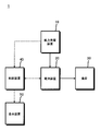
- FIG. 1 shows a schematic configuration of a battery system 1 according to an embodiment of the present invention
- FIG. 2 shows a specific configuration of the battery device 20 and the like.
- the dotted lines shown in FIGS. 1 and 2 indicate signal lines (wired or wireless communication lines) that can transmit and receive various types of information to and from the control device 40.
- the battery system 1 includes a wind power generator 10, a battery device 20, a load 30, a control device 40, and a display device 50.
- the battery system 1 supplies power generated by the wind power generator 10 to the battery device 20, and supplies power charged (stored) in the battery device 20 to the load 30.
- the battery system 1 of the present embodiment is not limited to the above configuration, and for example, a configuration may be added in which power generated by the wind power generator 10 is converted and then directly supplied to the load 30. In this case, power can be supplied to the load 30 by combining the power generated by the wind power generator 10 and the power charged by the battery device 20.
- the wind power generator 10 is a power supply device that generates three-phase AC power (AC power) by rotating a rotating machine with wind power, which is natural energy, and the configuration itself is the same as that of a general wind power generator. .
- the wind turbine generator 10 supplies the generated AC power to the battery device 20 via the power wiring.
- the battery device 20 converts AC power supplied from the wind power generator 10 into DC power and charges (stores) it. In addition, the battery device 20 converts the supplied DC power into power suitable for the load 30 and supplies it. As shown in FIG. 2, the battery device 20 includes substantially the same battery units 20A to 20C connected in parallel.
- the battery unit 20 ⁇ / b> A includes a battery module 21 ⁇ / b> A in which a plurality of chargeable / dischargeable battery cells are connected in series, a converter 22 ⁇ / b> A that receives AC power input from the wind power generator 10 and converts it into DC power, and the wind power generator 10. And a switch 23A that can cut off the input of AC power to the converter 22A.
- the battery unit 20B includes a battery module 21B, a converter 22B, and a switch 23B so as to have substantially the same function and configuration as the battery unit 20A.
- the battery unit 20C includes a battery module 21C, a converter 22C, and a switch 23C so as to have substantially the same function and configuration as the battery unit 20A.
- the battery units 20A to 20C can be supplied with the AC power from the same common power wiring.
- the battery system 1 of the present embodiment includes three battery units 20A to 20C as battery units connected in parallel, but the number of battery units is not limited to three, and may be at least two or more. That's fine. Thereby, for example, the number of battery units can be appropriately changed according to various conditions such as the maximum amount of power generated by the wind power generator 10 or the amount of power required by the load 30.
- Each of the battery modules 21A to 21C is an assembled battery as a DC power source configured by connecting a plurality of battery cells in series, and charges the electric power converted by the converters 22A to 22C, respectively.
- Each battery cell constituting each of the battery modules 21A to 21C is a chargeable / dischargeable battery cell.
- a battery cell of a lithium ion secondary battery can be used.
- the number of battery cells constituting each of the battery modules 21A to 21C can be determined according to the maximum amount of power generated by the wind power generator 10, the number of battery units connected in parallel, or the amount of power required by the load 30. .
- the battery module 21A a voltage sensor V 1 for measuring the voltage across the battery module 21A, a current sensor I 1 for measuring the current flowing through the battery module 21A is provided.
- the battery module 21B a voltage sensor V 2 for measuring the voltage across the battery module 21B, a current sensor I 2 for measuring the current flowing through the battery module 21B is provided.
- the battery module 21C a voltage sensor V 3 for measuring the voltage across the battery module 21C, a current sensor I 3 which measures the current flowing through the battery module 21C is provided.
- the voltage values measured by the voltage sensors V 1 to V 3 and the current values measured by the current sensors I 1 to I 3 are sent to the control device 40 via signal lines.
- a voltage sensor may be provided for each battery cell constituting the battery modules 21A to 21C.
- the converters 22A to 22C are power conversion units that convert AC power supplied from the wind power generator 10 into DC power.
- the converters 22A to 22C are controlled to start (ON) and stop (OFF) in response to a command from the control device 40.
- converters 22A to 22C generate a power loss when converting input AC power into DC power.
- FIG. 3 is a relationship diagram showing the relationship between the input power of a general converter and the conversion efficiency.
- the maximum input (maximum input power value) Pmax and the maximum efficiency input (maximum efficiency input power value) Pe differ for each converter manufacturer. As shown in FIG. 3, in a general converter, when the input power becomes smaller than the input Pe at the maximum efficiency, the conversion efficiency suddenly decreases. The conversion efficiency tends to decrease gently. Therefore, various converters can be applied to the battery system 1 of the present embodiment by using the maximum input Pmax and the maximum efficiency input Pe that are generalized values. In the battery system 1 of the present embodiment, the converters 22A to 22C use converters having substantially the same characteristics.
- the switch 23A is switching means for switching whether or not to interrupt the input of AC power via the power wiring from the wind power generator 10 to the converter 22A.
- the switch 23B is switching means for switching whether or not to interrupt the input of AC power from the wind turbine generator 10 to the converter 22B via the power wiring.
- the switch 23C is switching means for switching whether or not to interrupt input of AC power from the wind turbine generator 10 to the converter 22C via the power wiring.
- each of the switches 23A to 23C When each of the switches 23A to 23C is ON, AC power is supplied from the wind power generator 10 to each of the converters 22A to 22C, and when it is OFF, AC power is supplied from the wind power generator 10 to each of the converters 22A to 22C. Is cut off.
- the control device 40 desirably controls the converters 22A to 22C corresponding to the switches 23A to 23C to stop when the switches 23A to 23C are turned OFF. In this case, the power consumed wastefully by converters 22A to 22C can be suppressed.
- the load 30 is supplied with power from the battery device 20.
- the load 30 is an AC power load driven by AC power or a DC power load driven by DC power.
- each of the battery units 20A to 20C is provided with an inverter (not shown) that converts the DC power of each of the battery units 20A to 20C into AC power.
- each of the battery units 20A to 20C includes a DC-DC converter that converts the DC power of each of the battery units 20A to 20C into a DC power (DC voltage) desired by the load 30 ( (Not shown) is provided.
- the control device 40 generates wind power based on the supply power amount (generated power amount) of the power that can be supplied from the wind power generator 10, the charging state of each of the battery modules 21A to 21C, and the power conversion efficiency of each of the converters 22A to 22C.
- the battery device 20 is controlled to select at least one of the battery units 20A to 20C to which AC power is to be supplied from the device 10.
- the control device 40 controls the display device 50 to display various information such as the amount of power supplied to the wind power generator 10 and the charging state of the battery unit on the display device 50 as appropriate.
- the control device 40 includes, for example, a storage unit 41, an acquisition unit 42, a selection unit 43, and a switching unit 44 as processing functions for charging the battery units 20A to 20C, as shown in FIG.
- the control device 40 includes, for example, a processor for performing various calculations and control, a temporary storage of information (data), a RAM that functions as a working area at the time of control, a ROM that stores programs, and peripheral circuits. It is comprised and the processing function of said each part is realizable.
- the charging operation of the battery system 1, that is, a specific control flow performed by the control device 40 will be described later.
- the storage unit 41 stores information on the reference power value corresponding to the predetermined power conversion efficiency of the converters 22A to 22C.
- the maximum efficiency input Pe corresponding to the optimum power conversion efficiency described with reference to FIG. 3 is set as the reference power value corresponding to the predetermined power conversion efficiency.
- the reference power value is not limited to the maximum-efficiency input Pe.
- the acquisition unit 42 obtains information on the amount of power supplied by the wind turbine generator 10 and information on each voltage value and each current value of the battery modules 21A to 21C included in each of the plurality of battery units 20A to 20C at a predetermined timing. Get in.
- the acquisition unit 42 calculates the charge rate SOC (state of charge) of each of the battery units 20A to 20C using a known calculation method based on the acquired voltage value and current value, and the calculation result is selected by the selection unit 43.
- the charge rate SOC is a ratio (percentage) representing the state of charge of the battery module, that is, how much charge remains with respect to the capacity of the battery when fully charged.
- the charge rate SOC can be calculated using a known calculation method based on the voltage for each battery module and the current flowing for each battery module.
- the predetermined timing can be, for example, a timing immediately after the start of charging and a timing at regular intervals after the start of charging.
- the selection unit 43 includes information on the reference power values of the converters 22A to 22C stored in the storage unit 41, information on the amount of supplied power acquired by the acquisition unit 42, and the charge rates SOC of the battery modules 21A to 21C. Based on the information, the number of battery units that can distribute the supplied power amount to the power amount equal to or higher than the reference power value is determined, and the battery unit that supplies power from the wind power generator 10 among the plurality of battery units 20A to 20C. Select the determined number. Further, when the supplied power amount is lower than the sum of the reference power values of the plurality of battery units 20A to 20C, the selection unit 43 determines the battery unit 20A based on the information on the charging rate SOC of each of the battery modules 21A to 21C.
- Priority is determined to supply power to 20C in ascending order of charge state (for example, in ascending order of charge rate SOC), and the reference power value, supply power amount, and charge rate SOC of each battery unit 20A to 20C are determined. Based on the above, the number that can distribute the supplied power amount to the power amount equal to or higher than the reference power value is determined, and the determined number of battery units are selected according to the above priority.
- the switching unit 44 is configured so that at least one battery unit included in at least one battery unit among the battery units 20A to 20C selected by the selection unit 43 is in a charged state. It is determined whether or not the state of charge of the battery module provided is the same or substantially the same. When the switching unit 44 determines that the respective charging states are the same or substantially the same, the switching unit 44 selects the battery unit including the battery module in the charged state selected by the selection unit 43 and the same or substantially the same. The electric power supplied from the wind power generator 10 is alternately switched and supplied to battery units having the same or substantially the same charging state.
- the display device 50 displays information for various users such as the amount of power supplied from the wind power generator 10 and the charging state of the battery unit, and is a monitor such as a general liquid crystal panel.
- the display device 50 may be provided as necessary, and may be omitted in the battery system 1 of the present embodiment.
- the number of battery units is represented by a fixed value N.
- N 3
- Pmax 100 kW
- Pe 40 kW
- the state of charge of each battery cell is expressed using the charge rate SOC of the battery unit.
- the respective charging rates SOC of the battery modules 21A to 21C before charging are 80%, 60%, and 70%, respectively.
- the control device 40 acquires information on the amount of power P supplied from the wind power generator 10 from the wind power generator 10 (step S100). In this charging operation process, it is assumed that the control device 40 has acquired information from the wind power generator 10 that the supplied power amount P of the wind power generator 10 is 100 kW, for example.
- the control device 40 divides the supplied power amount P by the number N of battery units from the information on the supplied power amount P acquired from the wind power generator 10.
- the control device 40 determines whether or not the divided value P / N is greater than or equal to the reference power value Pb (step S101). That is, in this charging operation process, the control device 40 has a value P / N obtained by dividing 100 kW, which is the supplied power amount P, by “3”, which is the number N of battery units, is 40 kW or more, which is the reference power value Pb. Determine whether or not.
- step S101: Yes when the divided value P / N is equal to or greater than the reference power value Pb (step S101: Yes), the control device 40 connects the switches 23A to 23C of the battery units 20A to 20C via the signal lines.
- a control signal is sent to turn on each of the switches 23A to 23C (step S102). In this case, even if each of the switches 23A to 23C is turned on, the power input to each of the converters 22A to 22C is equal to or higher than the reference power value Pb. Modules 21A-21C can be charged.
- the control device 40 also sends a control signal to each of the converters 22A to 22C of the battery units 20A to 20C via the signal line to activate the converters 22A to 22C.
- the control device 40 acquires information on the supplied power amount P from the wind power generator 10 again (step S103).
- the control device 40 divides the supplied power amount P by the number N of battery units from the acquired information on the supplied power amount P, and determines whether or not the divided value P / N is equal to or greater than the reference power value Pb. (Step S104).
- This number N is determined to be the number N that can supply power equal to or higher than the reference power value Pb to each of the battery units 20A to 20C when the supplied power amount P is distributed to each of the battery units 20A to 20C.
- the amount of supplied power P changes, so the number of optimal battery units that can be supplied with power that is equal to or higher than the reference power value Pb also changes. . Therefore, it is preferable to change the optimal number of battery units that receive power supply according to the power supply amount P.
- the timing for acquiring the information on the power supply amount P can be appropriately set according to factors such as the characteristics of the wind turbine generator 10, for example.
- step S104 when the divided value P / N is equal to or greater than the reference power value Pb, that is, when it is not necessary to change the number N of battery units that supply power (step S104: Yes), The control device 40 determines whether or not the battery modules 21A to 21C have been charged (step S105).
- the end of charging in each of the battery modules 21A to 21C means that, for example, when all of the battery modules 21A to 21C are fully charged, or the power charged in each of the battery modules 21A to 21C needs to be discharged. This is the case.
- step S105: Yes the process flow is finished.
- step S105: No the process proceeds to step S103. In this charging operation process, if the supplied power amount P is 100 kW and the number N of battery units is 3, the divided value P / N is about 33 kW, which is smaller than the reference power value Pb, 40 kW.
- the processes of S105 are not performed.
- step S101 when the divided value P / N is smaller than the reference power value Pb (step S101: No (or step S104: No)), the control device 40 Information indicating the state of charge of the battery modules 21A to 21C is acquired, and the charge rate SOC is calculated (step S106).
- the divided value P / N is about 33 kW, which is smaller than 40 kW which is the reference power value Pb. Therefore, the control device 40 measures the voltage values measured by the voltage sensors V 1 to V 3 and the current sensors I 1 to I 3 as information indicating the charging states of the battery modules 21A to 21C.
- Each current value is acquired from each voltage sensor V 1 to V 3 and each current sensor I 1 to I 3 via a signal line.
- the control device 40 calculates the charging rate SOC of each of the battery modules 21A to 21C from the acquired voltage value and current value using a known calculation method. As described in the above preconditions, in this charging operation process, as a result of the calculation by the control device 40, the charging rate SOC (initial charging rate SOC) before the charging operation process of each of the battery modules 21A to 21C is respectively 80%, 60%, and 70%.
- control device 40 determines a priority order for supplying power to each of the battery units 20A to 20C based on the acquired charging rate SOC of each of the battery modules 21A to 21C (step S107). That is, control device 40 determines the priority for supplying power to battery units 20A to 20C in ascending order of charge rate SOC.
- the acquired charging rates SOC of the battery modules 21A to 21C are 80%, 60%, and 70%, respectively.
- the unit 20B is determined as No. 1
- the battery unit 20C is determined as No. 2
- the battery unit 20A is determined as No. 3.
- Each process of steps S108 to S111 is a process of adjusting the number of battery units to which power is supplied from the wind turbine generator 10 so that the power supplied to each battery unit is equal to or higher than the reference power value Pb.
- Step S114 the control device 40 sends a control signal to the corresponding switch via the signal line to supply P / M power from the first to the Qth battery units with the priority order, and turns on the switch.
- the switches 23B and 23C are turned ON, power of 40 kW or more, which is the reference power value Pb, is input to the converters 22B and 22C.
- the battery modules 21B and 21C are maintained in a state where the power conversion efficiency of the converters 22B and 22C is high when charged.
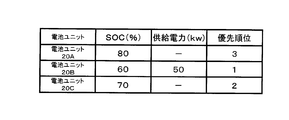
- the results of performing the processing so far are shown in the table of FIG. 7A.
- step S ⁇ b> 115 the control device 40 acquires information indicating the state of charge of the battery module being charged, and calculates the charge rate SOC (step S ⁇ b> 115). That is, in the present charging operation process, the control device 40 uses the voltage sensors V 2 to 21 as the voltage values and current values of the battery modules 21B and 21C as information indicating the charging state of the battery modules 21B and 21C being charged. to get through a signal line from V 3 and the current sensor I 2 ⁇ I 3. Further, the control device 40 calculates the charging rate SOC of each of the battery modules 21B and 21C using the acquired voltage values and current values of the battery modules 21B and 21C.
- the control device 40 uses the voltage sensors V 1 to V 3 and the current sensors I for the voltage values and current values of all the battery modules 21A to 21C as well as the battery module being charged. obtained via the signal line from the 1 ⁇ I 3, it may be calculated charging rate SOC of each battery module 21A ⁇ 21C. In this case, a more accurate determination can be made by the processing in step S116 below.
- step S116 When the charging rate SOC of the battery module being charged has reached the charging rate SOC of the priority order Q + 1th battery module (step S116: Yes), the control device 40 reaches the charging rate SOC of the priority order Q + 1th battery module.
- the signal line is connected to the corresponding switch so that the power P / M is evenly supplied to the battery unit having the battery module that has been reached and the battery unit having the battery module having the priority Q + 1.
- a signal is sent through the switches, and the respective switches are turned on and off at a predetermined timing (step S117). At this time, the P / M power is still supplied to the battery units that have not reached the charge rate SOC of the priority order Q + 1 battery module.
- step S116: No the process proceeds to step S120.
- the control device 40 turns ON / OFF the respective switches 23A and 23C in order to mutually supply 50 kW of power to the battery unit 20A and the battery unit 20C.
- a predetermined timing That is, 50 kW is alternately supplied to the battery unit 20A and the battery unit 20C.
- the battery module 21A and the battery module 21C are charged equally.
- power 50 kW is still supplied to the battery unit 20B and the battery module 21B is charged.
- the predetermined timing for switching the switch 23A and the switch 23C to each other can be set, for example, every 50 msec to 100 msec.
- the supplied power amount P acquired in the process of step S120 is a predetermined power compared to the supplied power amount P acquired in the previous process (for example, the supplied power amount P acquired in the process of step S101). This process is performed to determine whether or not the amount has changed beyond the quantity range.
- the predetermined power amount range is, for example, a range of change in the supplied power amount P when the charge efficiency in the battery system 1 is improved by changing the number M of battery units that supply power from the wind power generator 10. . If the relational expression is satisfied (step S121: Yes), the process proceeds to step S122. If the relational expression is not satisfied (step S121: No), the process proceeds to step S101.
- step S122 when the control device 40 determines that the charging is not finished (step S122: No), the process returns to the process of step S115. On the other hand, when the control device 40 determines that the charging is finished (step S122: Yes), the operation process of the battery system 1 is finished.
- a signal is sent to switch each switch ON and OFF at a predetermined timing.
- the control device 40 first supplies 50 kW to each of the battery units 20A and 20B, then supplies 50 kW to each of the battery units 20A and 20C, and further supplies 50 kW to each of the battery units 20B and 20C.
- the switches 23A to 23C are switched on and off at a predetermined timing so that two battery units of the battery units 20A to 20C are sequentially selected and each supply 50 kW of power. . That is, two battery modules are alternately selected from the battery units 20A to 20C, and 50 kW is supplied to the two selected battery modules.
- the process proceeds to step S120 and subsequent steps, and when the control device 40 determines that the charging is finished, this processing flow is finished.
- the battery system 1 of the present embodiment operates.
- the case where the power supply amount P of the wind turbine generator 10 is 100 kW has been described in the process of the first step S100, but as another example, the case where the power supply amount P is 50 kW is illustrated.
- step S100 the control device 40 acquires information on the power supply amount P (50 kW) from the wind power generator 10.
- the result of performing the processing up to step S114 is shown in the table of FIG. 8A.
- the control device 40 determines that the battery module 21B included in the battery unit 20B has reached the charging rate SOC, the process proceeds to step S117.
- step S117 the control device 40 switches ON / OFF of the switch 23B and the switch 23C that supply power to the battery unit 20B and the battery unit 20C to each other at a predetermined timing. That is, 50 kW is alternately supplied to the battery unit 20B and the battery unit 20C.
- step S121 if the supplied power amount P acquired by the control device 40 in the process of step S120 is not changed from the previous supplied power amount P of 50 kW, the process proceeds to step S121.
- step S122 it is assumed that charging is still in progress at this stage, and the process returns to step S115.
- the control device 40 determines that both 21B and 21C have arrived, the process proceeds to step S117.
- the control device 40 sequentially turns on and off the respective switches 23A, 23B, and 23C that supply power to the battery unit 20A, the battery unit 20B, and the battery unit 20C at predetermined timings. Switch alternately.
- the control device 40 first supplies 50 kW of power to the battery unit 20A, then supplies 50 kW of power to the battery unit 20B, and further supplies 50 kW of power to the battery unit 20C.
- One battery unit is sequentially selected from the battery units 20A to 20C, and power of 50 kW is supplied. That is, 50 kW is alternately supplied to the battery units 20A to 20C.
- the battery module 21A, the battery module 21B, and the battery module 21C can be charged uniformly.
- the process proceeds to step S120 and subsequent steps, and when the control device 40 determines that the charging is finished, this processing flow is finished.
- each charging information indicating the charging state of the battery modules 21A to 21C is acquired, and the priority for supplying power to the battery unit is determined in ascending order of the charging state. It is possible to make the state of charge of the battery module uniform. In addition, due to factors such as the usage status of each battery module and the presence of a degraded battery module among multiple battery modules, it is also assumed that the voltage varies between battery modules. If a plurality of battery modules connected in parallel are charged at the same time, a mutual charging action occurs between the battery modules, resulting in a decrease in charging efficiency.
- the priority order is determined in ascending order of charge state, even if power is supplied to a plurality of battery units, it is possible to select and supply battery units having battery modules having close charge states. It is possible to suppress the mutual charging effect caused by the difference in voltage between the two.
- the charging state of the battery module that is selected by the selection unit 43 and in which the charging state of the battery module being charged is at least one of the non-selected battery units is charged.
- the supply destination of the power supplied from the wind power generator 10 is alternately switched between battery units having the same or substantially the same charged state at a predetermined timing.
- the state of charge is increased to some extent, and power is evenly supplied to at least two battery units having the same or substantially the same state of charge, while power is supplied to battery units in a low state of charge. Can continue to supply.
- a battery unit with a low state of charge can be charged quickly so that power can be continuously supplied to achieve a charge rate equivalent to that of other battery modules, and the state of charge of the battery modules is the same or substantially the same.
- the same battery unit can be charged while maintaining equality.
- the battery system 1 of the present embodiment even when the supplied power amount P is changed by acquiring information related to the supplied power amount P of the power supplied by the wind turbine generator 10 at a predetermined timing. Thus, it is possible to determine the optimal number of battery units that receive power supply according to the supplied power amount P, and to maintain high charging efficiency at all times.
- a wind power generator is used as an example of the power supply device.
- the present invention is not limited to this, and for example, solar power generation or a commercial power supply may be used.
- the power conversion unit disposed between the power supply and the battery unit may use a DC / DC converter.
- the reference power value is appropriately set based on the power conversion efficiency of the DC / DC converter.
- the control device 40 may acquire information on the supplied power amount P only immediately after the start of charging. Good.
- the control apparatus 40 acquires each charge information which shows the charge condition of a battery module
- this invention is not limited to this,
- the control device 40 has a plurality of battery units connected in parallel according to the amount of power supplied from the wind power generator 10 and taking into account the power conversion efficiency of the converters 22A to 22C. Select the battery unit to be supplied from 20A to 20C, and then turn ON / OFF the switches 23A to 23C so that power is evenly supplied to the battery units 20A to 20C including the non-selected battery units. It can be controlled to switch to each other sequentially.
- the control apparatus 40 determined the priority which supplies electric power to a battery unit based on each charging information in order with the low charge state, it supplied electric power in the determined order.
- the present invention is not limited to this.
- the control device 40 also considers the power conversion efficiency of the converters 22A to 22C and supplies the amount of power supplied from the wind power generator 10. Accordingly, the battery units to be supplied are selected from the plurality of battery units 20A to 20C connected in parallel, and the switches 23A to 23C are turned on and off at a predetermined timing so as to supply power evenly. It can also be controlled to switch to On the other hand, when there is a charged battery unit that does not fall within the predetermined range, the control device 40 continues to supply power only to the charged battery unit, and switches the switches between the other battery units evenly. May be supplied.
- the control apparatus 40 is selected by the selection part 43, and the charge state of the battery module in charge is the same as the charge state of the battery module which at least 1 battery unit has among non-selected battery units.
- the supply destination of the power supplied from the power supply device is alternately switched between the battery units having the same or substantially the same charging state, but the present invention is not limited to this.
- the control device 40 selects the non-selected battery unit until the state of charge of all the battery modules selected and being charged is the same as or substantially the same as the state of charge of the battery module of the non-selected battery unit. You may control to stop supply of electric power.
- each unit is connected to be able to communicate with the control device 40. It can also be configured on the network or in preparation for other devices.
- each part according to a use is each provided in the control apparatus 40, you may comprise each part provided in the control apparatus 40 collectively, and one part may be comprised. Further, it may be divided into a plurality of parts.
- the battery system of the present invention can be applied to a system that uses at least charging battery modules provided in a plurality of battery units, for example, stores power in a secondary battery during regeneration of a motor such as an electric vehicle,
- the power stored in the secondary battery can be used as a moving system that is used when the motor is driven.
- a power storage system that stores power generated by using natural energy such as wind power generation or solar power generation in a secondary battery, and uses the power stored in the secondary battery for household electrical equipment
- the power stored in the secondary battery can be used as a stationary system such as a power selling system that sells power to an electric power system as an AC power load.
- SYMBOLS 1 Battery system, 10 ... Wind power generator (power supply device), 20 ... Battery device, 20A-20C ... Battery unit, 21A-21C ... Battery module, 22A-22C ... Converter (power converter), 23A-23C ... Switch , 30 ... load, 40 ... control device, 50 ... display device.
Landscapes
- Engineering & Computer Science (AREA)
- Power Engineering (AREA)
- Transportation (AREA)
- Mechanical Engineering (AREA)
- Sustainable Energy (AREA)
- Sustainable Development (AREA)
- Life Sciences & Earth Sciences (AREA)
- Manufacturing & Machinery (AREA)
- Chemical & Material Sciences (AREA)
- Chemical Kinetics & Catalysis (AREA)
- Electrochemistry (AREA)
- General Chemical & Material Sciences (AREA)
- Charge And Discharge Circuits For Batteries Or The Like (AREA)
- Supply And Distribution Of Alternating Current (AREA)
- Secondary Cells (AREA)
Abstract
電力を供給する電源装置と、電源装置から供給される電力を変換する電力変換部と、電力変換部で変換された電力を充電する電池モジュールをそれぞれ備える実質的同一の電池ユニットが複数且つ並列に接続された電池装置と、電力変換部の所定の電力変換効率に対応する基準電力値に関する情報を記憶する記憶部と、電源装置が供給する電力の供給電力量に関する情報を取得する取得部と、記憶部に記憶された基準電力値の情報と取得部が取得した供給電力量の情報とに基づいて、供給電力量を前記基準電力値以上の電力量に分配可能な電池ユニットの個数を決定し、複数の電池ユニットのうち電源装置から電力を供給する電池ユニットを前記決定した個数選択する選択部とを有する制御装置と、を備える電池システム。
Description
本発明は、電池システムに関し、特に、複数の電池モジュールを効率よく充電する電池システムに関する。
本願は、2011年7月28日に出願された特願2011-165219号について優先権を主張し、その内容をここに援用する。
本願は、2011年7月28日に出願された特願2011-165219号について優先権を主張し、その内容をここに援用する。
充放電可能な複数の電池セルからなる電池モジュールをそれぞれ並列に接続した電池システムが知られている。この電池システムは、例えば、風力発電や太陽光発電などの自然エネルギーを利用した電源からの電力や商用電源からの電力をインバータやコンバータなどの電力変換器を介して電池モジュールを充電する。
並列に接続された複数の電池モジュールを充電する方法として、例えば、電源からの電力を1つの電池モジュールを選択して供給し、この選択した電池モジュールが満充電になった場合に、電力の供給先を他の電池モジュールに切り換えていく方法(例えば、特許文献1参照)がある。また、電源からの電力を1つの電池モジュールを経時的に順番に選択して供給する方法(例えば、特許文献2参照)が知られている。また、電源からの電力を複数の電池モジュールに対して並列に供給する方法も知られている(例えば、特許文献3参照)。
しかしながら、特許文献1及び特許文献2に記載の発明は、複数の電池モジュールを個別に充電するために、供給される電力量が十分に大きく、且つ、充電時間を一定時間以上確保する必要がある。そのため、供給される電力量が十分でない場合や充電時間が短い場合、並列に接続された電池モジュールを均等に充電することができないという課題がある。例えば、風力発電や太陽光発電などの自然エネルギーを利用した電源は、供給可能な電力量が一定ではないため、供給可能な電力量が小さいとき、1つの電池モジュールを充電した後、他の電池モジュールを十分に充電できない場合がある。また、充電を開始した直後に電源からの電力の供給がなくなった場合や、電源からの電力の供給が十分であっても電池モジュールの電力を負荷に対して放電する必要が生じ、充電モードから放電モードに切り換えなければならない場合など、充電時間が短いときにも、各電池モジュールを均等に充電できない。このように複数の電池モジュールを均等に充電できないことで、例えば、特定の電池モジュールに充放電の負荷が集中してしまい、他の電池モジュールと比較して劣化が進んでしまう。そのため、電池モジュールを均等に充電することが望まれている。
特許文献3に記載の発明は、複数の電池モジュールを並列に充電するため、各電池モジュールに供給される電力が均等になる。しかし、電力が分配されるため、供給される電力量が十分に大きくないと、例えば、各電池モジュールと電源との間にそれぞれ電力変換器が配置されている場合、各電力変換器に対して入力される電力が非常に小さくなってしまう。そのため、電力変換器の電力変換効率が落ち、結果として、各電池モジュールの充電効率も落ちてしまうという課題がある。インバータやコンバータなどの電力変換器は、一般に、一定以上の入力電力がないと、その電力変換効率が極端に落ちてしまうことが知られている。
本発明は、並列にそれぞれ接続された電池モジュールの充電効率を高めることができる電池システムを提供することを目的とする。
本発明に係る電池システムの第一態様は、電力を供給する電源装置と、電源装置から供給される電力を変換する電力変換部と、電力変換部で変換された電力を充電する電池モジュールと、をそれぞれ備える実質的同一の電池ユニットが複数且つ並列に接続された電池装置と、電力変換部の所定の電力変換効率に対応する基準電力値に関する情報を記憶する記憶部と、電源装置が供給する電力の供給電力量に関する情報を取得する取得部と、記憶部に記憶された基準電力値に関する情報と取得部が取得した供給電力量に関する情報とに基づいて、供給電力量を上記基準電力値以上の電力量に分配可能な電池ユニットの個数を決定し、複数の電池ユニットのうち電源装置から電力を供給する電池ユニットを上記決定した個数選択する選択部とを有する制御装置と、を備える。
上記電池システムによれば、電力変換部の電力変換効率を考慮しつつ、電源装置からの供給電力量に応じて並列にそれぞれ接続された複数の電池ユニットのうち電力供給すべき電池ユニットを選択することができるので、最適な個数の電池モジュールを高い充電効率を維持して充電することができる。
本発明に係る電池システムの第二態様では、上記第一態様の電池システムにおける前記取得部が、前記複数の電池ユニットがそれぞれ備える前記電池モジュールの充電状態を示す各充電情報を取得するようにしてもよい。また、前記選択部は、前記記憶部に記憶された前記基準電力値に関する情報と前記取得部が取得した前記供給電力量に関する情報及び前記各充電情報とに基づいて、前記供給電力量を前記基準電力値以上の電力量に分配可能な前記電池ユニットの個数を決定し、前記複数の電池ユニットのうち前記電源装置から電力を供給する前記電池ユニットを前記決定した個数選択するようにしてもよい。
本発明に係る電池システムの第三態様では、上記第二態様の電池システムにおける前記選択部が、前記供給電力量が前記複数の電池ユニットのそれぞれの前記基準電力値の総和より低い場合、前記取得部が取得した前記各充電情報に基づいて、前記電池ユニットに電力を供給する優先順位を前記充電状態の低い順に決定してもよい。また、前記選択部は、前記記憶部に記憶された前記基準電力値に関する情報と前記取得部が取得した前記供給電力量及び前記各充電情報に関する情報とに基づいて、前記供給電力量を前記基準電力値以上の電力量に分配可能な前記電池ユニットの個数を決定し、前記決定した個数の前記電池ユニットを前記優先順位に従って選択するようにしてもよい。
本発明に係る電池システムの第四態様では、上記第三態様の電池システムにおける前記制御装置が、前記選択部により選択された前記電池ユニットのうち少なくとも1つの電池ユニットが備える前記電池モジュールの前記充電状態が、前記選択部が非選択の前記電池ユニットのうち少なくとも1つの電池ユニットの備える前記電池モジュールの前記充電状態と同一又は略同一となった場合、前記選択部により選択され、且つ、前記同一又は略同一となった前記充電状態の電池モジュールを備える前記電池ユニットに対して前記電源装置から供給されていた電力を、前記充電状態が同一又は略同一となった前記電池モジュールを備える少なくとも2つ以上の前記電池ユニットに対して交互に切り換えて供給する切換部を更に有するようにしてもよい。
本発明に係る電池システムの第五態様では、上記第一態様から第四態様の何れか一つの電池システムにおける前記取得部が、電源装置が供給する電力の供給電力量に関する情報を所定のタイミングで取得するようにしてもよい。
本発明に係る電池システムの第六態様では、上記第一態様から第五態様の電池システムにおける前記所定の電力変換効率が、前記電力変換部における最大の電力変換効率であってもよい。
本発明の上記態様に係る電池システムによれば、電力変換部の電力変換効率を考慮して、高い充電効率を維持した状態で、並列にそれぞれ接続された電池モジュールを充電することができる。
以下、本発明の一実施形態に係る電池システム1について説明する。下記実施形態においては、電源装置として風力発電装置を用い、電力変換部として交流電力を直流電力に変換するコンバータを用いた場合を一例にして説明する。
図1は、本発明の一実施形態における電池システム1の概略的な構成を示し、図2は、電池装置20等の具体的な構成を示している。図1及び図2に示す点線は、制御装置40との間で種々の情報を送受可能な信号線(有線又は無線の通信線)を示している。
図1に示すように、電池システム1は、風力発電装置10、電池装置20、負荷30、制御装置40、及び表示装置50を有している。この電池システム1は、風力発電装置10で発生した電力を電池装置20に供給し、電池装置20に充電(貯蔵)された電力を負荷30に供給する。本実施形態の電池システム1は、上記構成に限定されず、例えば、風力発電装置10で発生した電力を電力変換した後、負荷30に直接供給するような構成を追加してもよい。この場合、風力発電装置10で発生した電力と電池装置20で充電されている電力とを組み合わせて負荷30に電力を供給することができる。
風力発電装置10は、自然エネルギーである風力によって回転機を回転させて三相交流電力(交流電力)を発生させる電源装置であって、その構成自体は、一般的な風力発電装置と同様である。風力発電装置10は、発生した交流電力を、電力配線を介して電池装置20に供給する。
電池装置20は、風力発電装置10から供給された交流電力を直流電力に変換して充電(貯蔵)する。また、電池装置20は、充電した直流電力を負荷30に適した電力に電力変換して供給する。
図2に示すように、電池装置20は、並列にそれぞれ接続された実質的同一の電池ユニット20A~20Cで構成されている。
図2に示すように、電池装置20は、並列にそれぞれ接続された実質的同一の電池ユニット20A~20Cで構成されている。
電池ユニット20Aは、複数の充放電可能な電池セルが直列に接続された電池モジュール21Aと、風力発電装置10から交流電力の入力を受けて直流電力に変換するコンバータ22Aと、風力発電装置10からコンバータ22Aへの交流電力の入力を遮断することができるスイッチ23Aとを備えている。電池ユニット20Bは、電池ユニット20Aと実質的に同一の機能及び構成を有するように、電池モジュール21Bと、コンバータ22Bと、スイッチ23Bとを備えている。電池ユニット20Cは、電池ユニット20Aと実質的に同一の機能及び構成を有するように、電池モジュール21Cと、コンバータ22Cと、スイッチ23Cとを備えている。上記電池ユニット20A~20Cには、互いに共通の同一の電力配線から上記交流電力が供給可能になっている。本実施形態の電池システム1は、それぞれ並列に接続される電池ユニットとして、電池ユニット20A~20Cの3つを備えているが、電池ユニットの数は3つに限られず、少なくとも2つ以上であればよい。これにより、例えば、風力発電装置10の最大発電電力量、又は負荷30の要求する電力量などの種々の条件に応じて、電池ユニットの数を適宜変更することができる。
各電池モジュール21A~21Cは、複数の電池セルを直列接続して構成された直流電源としての組電池であって、それぞれコンバータ22A~22Cで変換された電力を充電する。各電池モジュール21A~21Cを構成する各電池セルは、充放電可能な電池セルであって、例えば、リチウムイオン二次電池の電池セルを用いることができる。各電池モジュール21A~21Cを構成する電池セルの個数は、風力発電装置10の最大発電電力量や並列に接続される電池ユニットの数、又は負荷30の要求する電力量に応じて決めることができる。
電池モジュール21Aには、電池モジュール21Aの両端電圧を測定する電圧センサV1と、電池モジュール21Aに流れる電流を測定する電流センサI1とが設けられている。電池モジュール21Bには、電池モジュール21Bの両端電圧を測定する電圧センサV2と、電池モジュール21Bに流れる電流を測定する電流センサI2とが設けられている。電池モジュール21Cには、電池モジュール21Cの両端電圧を測定する電圧センサV3と、電池モジュール21Cに流れる電流を測定する電流センサI3とが設けられている。各電圧センサV1~V3で測定された各電圧値、及び各電流センサI1~I3で計測された各電流値は、信号線を介して制御装置40に送られる。電圧センサV1~V3が電池モジュール21A~21Cごとに設けられている場合について説明したが、例えば、電池モジュール21A~21Cを構成する電池セルごとに電圧センサを設けるようにしてもよい。
コンバータ22A~22Cは、風力発電装置10から供給される交流電力を直流電力に電力変換する電力変換部である。コンバータ22A~22Cは、制御装置40からの指令を受けて起動(ON)及び停止(OFF)が制御される。コンバータ22A~22Cは、一般に、入力された交流電力を直流電力に変換する際、電力損失を生じる。ここで、図3は、一般的なコンバータの入力される電力と変換効率との関係を表した関係図である。最大入力(最大入力電力値)Pmaxや最大効率時入力(最大効率時入力電力値)Peは、コンバータの製造メーカごとに異なる。図3に示すように、一般的なコンバータは、最大効率時入力Peより小さい入力電力になると急激に変換効率が低下し、最大効率時入力Peから最大入力Pmaxになるまでの間は、比較的なだらかに変換効率が低下する傾向にある。したがって、一般化した値である最大入力Pmaxや最大効率時入力Peを用いることで、様々なコンバータを本実施形態の電池システム1に適用することができる。本実施形態の電池システム1において、コンバータ22A~22Cは、実質的に同一特性のコンバータを用いている。
スイッチ23Aは、風力発電装置10からコンバータ22Aへの電力配線を介した交流電力の入力を遮断するか否かを切り換える切り換え手段である。スイッチ23Bは、風力発電装置10からコンバータ22Bへの電力配線を介した交流電力の入力を遮断するか否かを切り換える切り換え手段である。スイッチ23Cは、風力発電装置10からコンバータ22Cへの電力配線を介した交流電力の入力を遮断するか否かを切り換える切り換え手段である。これらスイッチ23A~23Cは、制御装置40からの指令を受けてON(閉)/OFF(開)を切り換える。各スイッチ23A~23Cが、ONであれば、風力発電装置10から各コンバータ22A~22Cへ交流電力が供給され、OFFであれば、風力発電装置10から各コンバータ22A~22Cへの交流電力の供給が遮断される。制御装置40は、スイッチ23A~23CをOFFにするとき、スイッチ23A~23Cのそれぞれに対応するコンバータ22A~22Cを停止するよう制御することが望ましい。この場合、コンバータ22A~22Cによって無駄に消費される電力を抑制することができる。
負荷30は、電池装置20から電力供給される。負荷30は、交流電力で駆動する交流電力負荷又は直流電力で駆動する直流電力負荷である。負荷30が交流電力負荷である場合、各電池ユニット20A~20Cには、各電池ユニット20A~20Cの直流電力を交流電力に変換するインバータ(図示せず)が設けられる。また、負荷30が直流電力負荷である場合、各電池ユニット20A~20Cには、各電池ユニット20A~20Cの直流電力を負荷30が所望する直流電力(直流電圧)に変換するDC-DCコンバータ(図示せず)が設けられる。
制御装置40は、風力発電装置10から供給可能な電力の供給電力量(発電電力量)、各電池モジュール21A~21Cの充電状態、及び各コンバータ22A~22Cの電力変換効率に基づいて、風力発電装置10から交流電力を供給すべき電池ユニット20A~20Cを少なくとも1つ選択するよう電池装置20を制御する。また、制御装置40は、表示装置50を制御して、風力発電装置10の供給電力量や電池ユニットの充電状態など各種の情報を、適宜、表示装置50に表示させる。
制御装置40は、電池ユニット20A~20Cを充電する処理機能として、例えば、図2に示すように、記憶部41、取得部42、選択部43、及び切換部44を有する。制御装置40は、例えば、種々の演算および制御を行うためのプロセッサ、情報(データ)を一時的に格納するとともに、制御時にワーキングエリアとして機能するRAM、プログラム等を格納するROM、及び周辺回路から構成され、上記各部の処理機能を実現することができる。電池システム1の充電動作、すなわち、制御装置40が行う具体的な制御フローについては後述する。
記憶部41は、コンバータ22A~22Cの所定の電力変換効率に対応する基準電力値に関する情報を記憶する。ここで、本実施形態の電池システム1においては、図3を用いて説明した、最適な電力変換効率に対応する最大効率時入力Peを、所定の電力変換効率に対応する基準電力値とする。基準電力値は、最大効率時入力Peに限られず、例えば、図3に示す電力変換効率が90(%)以上となる電力のうち、最も値が小さい入力電力値P’を用いるなど、電池システムの構成及びコンバータの電力変換効率の特性に応じて適宜設定することができる。
取得部42は、風力発電装置10が供給する電力の供給電力量に関する情報、及び複数の電池ユニット20A~20Cがそれぞれ有する電池モジュール21A~21Cの各電圧値及び各電流値の情報を所定のタイミングで取得する。取得部42は、取得した各電圧値及び各電流値により、公知の演算方法を用いて各電池ユニット20A~20Cの充電率SOC(state of charge)を演算し、この演算した結果を選択部43に通知する。充電率SOCは、電池モジュールの充電状態、すなわち、満充電時における電池の容量に対して充電残量がどのくらいかを表した比率(パーセント)である。この充電率SOCは、電池モジュールごとの電圧と、電池モジュールごとに流れる電流とにより、公知の演算方法を用いて演算することができる。上記所定のタイミングとは、例えば、充電開始直後のタイミング、及び充電開始後一定時間ごとのタイミングとすることができる。
選択部43は、記憶部41に記憶された各コンバータ22A~22Cの基準電力値に関する情報、取得部42が取得した供給電力量に関する情報、及び、各電池モジュール21A~21Cの各充電率SOCの情報に基づいて、供給電力量を上記基準電力値以上の電力量に分配可能な電池ユニットの個数を決定し、複数の電池ユニット20A~20Cのうち風力発電装置10から電力を供給する電池ユニットを上記決定した個数選択する。また、選択部43は、供給電力量が複数の電池ユニット20A~20Cのそれぞれの前記基準電力値の総和より低い場合、各電池モジュール21A~21Cの充電率SOCの情報に基づいて、電池ユニット20A~20Cに対して電力を供給する優先順位を充電状態の低い順(例えば、充電率SOCの低い順)に決定し、各電池ユニット20A~20Cの基準電力値と供給電力量と充電率SOCとに基づいて、供給電力量を基準電力値以上の電力量に分配可能な個数を決定し、この決定した個数の電池ユニットを上記優先順位に従って選択する。
切換部44は、選択部43により選択された電池ユニット20A~20Cのうち少なくとも1つの電池ユニットが備える電池モジュールの充電状態が、選択部43が非選択の電池ユニットのうち少なくとも1つの電池ユニットの備える電池モジュールの充電状態と同一又は略同一となったか否かを判断する。切換部44は、上記各充電状態が同一又は略同一となったと判断した場合、選択部43により選択され、且つ、同一又は略同一となった充電状態の電池モジュールを備える前記電池ユニットに対して風力発電装置10から供給されていた電力を、充電状態が同一又は略同一の電池ユニットに対しても交互に切り換えて供給する。
表示装置50は、例えば、風力発電装置10の供給電力量や、電池ユニットの充電状態など各種のユーザに向けた情報を表示するものであり、例えば、一般的な液晶パネルなどのモニタである。表示装置50は、必要に応じて設ければよく、本実施形態の電池システム1においては省略してもよい。
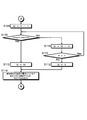
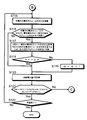
以下、図4~図6に示すフローチャートを参照して、制御装置40を用いて実施される本実施形態の電池システム1の充電動作処理について説明する。図4~図6のフローチャートで示される各処理は、処理内容に矛盾を生じない範囲で任意に順番を変更して又は並列に実行してもよい。
電池システム1の充電動作処理を説明するにあたり、図1及び図2に示す電池システム1を用いる。更に、以下の事項を前提とする。電池ユニットの個数を固定値Nで表す。図2に示すように、3つの電池ユニット20A~20Cを用いるので、N=3とする。コンバータ22A~22Cへの各最大入力電力値を固定値Pmaxで表し、Pmax=100kWとする。また、最大効率時入力電力値を固定値Peで表し、Pe=40kWとする。よって、図2に示す電池装置20の最大許容入力電力はN×Pmax=300kWとなる。さらに、制御装置40は、コンバータ22A~22Cにおいて所定の電力変換効率を有する基準電力値Pbとして、最適な電力変換効率に対応する最大効率時入力電力値Pe(=40kW)が予め記憶部41に記憶されている。
また、さらなる前提として、各電池セルの充電状態は、電池ユニットの充電率SOCを用いて表す。また、充電前の電池モジュール21A~21Cの各充電率SOC(電池システム1の充電動作処理前の初期値の充電率SOC)は、それぞれ80%、60%、70%とする。
以上を前提とし、以下、電池システム1の充電動作処理を説明する。
まず、制御装置40は、風力発電装置10の供給電力量Pの情報を風力発電装置10から取得する(ステップS100)。本充電動作処理において、制御装置40は、例えば、風力発電装置10の供給電力量Pが100kWであるとの情報を風力発電装置10から取得したものとする。
次いで、制御装置40は、上記風力発電装置10から取得した供給電力量Pの情報から、供給電力量Pを電池ユニットの個数Nで除算する。制御装置40は、この除算した値P/Nが基準電力値Pb以上であるか否かを判断する(ステップS101)。すなわち、本充電動作処理において、制御装置40は、供給電力量Pである100kWを電池ユニットの個数Nである「3」で除算した値P/Nが、基準電力値Pbである40kW以上であるか否かを判断する。
上記判断の結果、除算した値P/Nが、基準電力値Pb以上である場合(ステップS101:Yes)、制御装置40は、信号線を介して電池ユニット20A~20Cの各スイッチ23A~23Cに対して制御信号を送り、各スイッチ23A~23CをONとする(ステップS102)。この場合、各スイッチ23A~23CをONとしても、各コンバータ22A~22Cに入力される電力は、それぞれ基準電力値Pb以上となるので、コンバータ22A~22Cでの電力変換効率が高い状態で各電池モジュール21A~21Cを充電することができる。制御装置40は、各スイッチ23A~23CをONにする際、信号線を介して電池ユニット20A~20Cの各コンバータ22A~22Cに対しても制御信号を送り、各コンバータ22A~22Cを起動する。
ステップS102の処理後、制御装置40は、再度、供給電力量Pの情報を風力発電装置10から取得する(ステップS103)。制御装置40は、この取得した供給電力量Pの情報から、供給電力量Pを電池ユニットの個数Nで除算し、この除算した値P/Nが基準電力値Pb以上であるか否かを判断する(ステップS104)。このステップS103~S104の処理は、所定時間経過後に供給電力量Pが変化した場合、電池システム1における充電効率を高く維持するために、電力の供給を受ける電池ユニットの個数N(=3)を変えた方が良いか否かを判断する処理である。ステップS103よりも前の処理においては、ステップS101の処理で取得した供給電力量Pに基づいて電力の供給を受ける電池ユニットの個数N(=3)を決定している。この個数Nは、供給電力量Pを各電池ユニット20A~20Cに分配した場合に、各電池ユニット20A~20Cに基準電力値Pb以上の電力が供給可能な個数Nに決定される。しかし、風力発電装置10のように自然エネルギーを利用した電源装置においては、その供給電力量Pが変化するため、基準電力値Pb以上の電力の供給を受けられる最適な電池ユニットの個数も変化する。したがって、供給電力量Pに応じて電力の供給を受ける最適な電池ユニットの個数を変更することが好ましい。供給電力量Pの情報を取得するタイミングは、例えば、風力発電装置10の特性などの要因に応じて適宜設定できる。
ステップS104の処理において、上記除算した値P/Nが、基準電力値Pb以上である場合、すなわち、電力を供給する電池ユニットの個数Nを変更しなくても良い場合(ステップS104:Yes)、制御装置40は、各電池モジュール21A~21Cが充電終了したか否かを判断する(ステップS105)。ここで、各電池モジュール21A~21Cにおける充電終了とは、例えば、各電池モジュール21A~21Cの全てが満充電となった場合や、各電池モジュール21A~21Cに充電された電力を放電する必要が生じた場合である。充電終了であれば(ステップS105:Yes)、本処理フローは終了し、充電終了でなければ(ステップS105:No)、ステップS103の処理に移る。本充電動作処理では、供給電力量Pが100kW及び電池ユニットの個数Nが3であれば、除算した値P/Nは、約33kWとなり、基準電力値Pbである40kWより小さくなるため、ステップS102~S105の処理は行われない。
ステップS101の処理において(又は、ステップS104の処理において)、除算した値P/Nが基準電力値Pbより小さい場合(ステップS101:No(又は、ステップS104:No))、制御装置40は、各電池モジュール21A~21Cの充電状態を示す情報を取得し、充電率SOCを演算する(ステップS106)。本充電動作処理では、上記除算した値P/Nは、約33kWであり、基準電力値Pbである40kWより小さくなる。そのため、制御装置40は、各電池モジュール21A~21Cの充電状態を示す情報として、各電圧センサV1~V3で測定された各電圧値と、各電流センサI1~I3で計測された各電流値とを、各電圧センサV1~V3及び各電流センサI1~I3から信号線を介して取得する。制御装置40は、上記取得した各電圧値及び各電流値より、公知の演算方法を用いて各電池モジュール21A~21Cの充電率SOCを演算する。上記前提条件で述べたように、本充電動作処理においては、制御装置40による演算の結果、各電池モジュール21A~21Cの充電動作処理前の充電率SOC(初期値の充電率SOC)は、それぞれ80%、60%、70%となる。
次いで、制御装置40は、取得した各電池モジュール21A~21Cの充電率SOCに基づいて、各電池ユニット20A~20Cに対して電力を供給する優先順位を決定する(ステップS107)。すなわち、制御装置40は、電池ユニット20A~20Cに対して電力を供給する優先順位を充電率SOCの低い順に決定する。本充電動作処理において、取得した電池モジュール21A~21Cの充電率SOCは、それぞれ80%、60%、70%とされているため、前記制御装置40は、上記電力を供給する優先順位として、電池ユニット20Bを1番、電池ユニット20Cを2番、電池ユニット20Aを3番に決定する。
次に、図5に示すフローチャートに移り、制御装置40は、電力を同時に供給可能な電池ユニットの個数(同時にスイッチをON可能な個数)を変数Mで表し、M=N-1に設定する(ステップS108)。ステップS108~S111の各処理は、各電池ユニットに供給される電力が基準電力値Pb以上になるように、風力発電装置10から電力が供給される電池ユニットの数を調整する処理である。
制御装置40は、供給電力量Pを変数Mで除算した値P/Mが、基準電力値Pbより大きいか否かを判断する(ステップS109)。本充電動作処理では、供給電力量Pである100kWを、M(=N(3)-1)である「2」で除算した値P/Mが、基準電力値Pbである40kW以上であるか否かを判断する。
上記除算した値P/Mが基準電力値Pbより小さい場合(ステップS109:No)、制御装置40は、M=M-1に再設定して(ステップS110)、変数Mが2以上であれば(ステップS111:Yes)、ステップS109の処理に戻る。一方、変数Mが2より小さい場合(すなわち、変数Mが1の場合)(ステップS111:No)、制御装置40は、電力の供給可能対象とする電池ユニットの個数を変数Qで表し、Q=1と設定する(ステップS112)。
一方、上記除算した値P/Mが基準電力値Pb以上である場合(ステップS109:Yes)、制御装置40は、電力の供給可能対象とする電池ユニットの個数を変数Qで表し、Q=Mと設定する(ステップS113)。本充電動作処理では、上記除算した値P/Mは、50kWであり、この値は基準電力値Pbである40kWより大きいため、Q=M(2)となる。
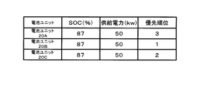
次いで、制御装置40は、優先順位が1番目からQ番目の電池ユニットまで各々P/Mの電力を供給するため、信号線を介して対応するスイッチに対して制御信号を送り、当該スイッチをONとする(ステップS114)。本充電動作処理では、ステップS113の処理において、Q=2に設定される。そのため、制御装置40は、スイッチ23B、23CをONとし、各コンバータ22B、22Cを起動して、優先順位が1番目の電池ユニット20Bから優先順位が2番目の電池ユニット20Cまで、各々供給電力として50kWを供給(充電)する。各スイッチ23B、23CがONとなることで、コンバータ22B、22Cには、それぞれ基準電力値Pbである40kW以上の電力が入力される。その結果、電池モジュール21B、21Cは充電されるときに、コンバータ22B、22Cの電力変換効率が高い状態で維持される。これまでの処理を行った結果を、図7Aの表に示す。
次に、図6のフローチャートに移り、ステップS114の処理後、制御装置40は、充電中の電池モジュールの充電状態を示す情報を取得し、充電率SOCを演算する(ステップS115)。すなわち、本充電動作処理において、制御装置40は、充電中の電池モジュール21B、21Cの充電状態を示す情報として、電池モジュール21B、21Cの各電圧値及び各電流値をそれぞれ各電圧センサV2~V3及び各電流センサI2~I3から信号線を介して取得する。さらに制御装置40は、取得した電池モジュール21B、21Cの各電圧値及び各電流値を用いて、電池モジュール21B、21Cそれぞれの充電率SOCを演算する。ステップS115の処理において、制御装置40は、充電中の電池モジュールのみならず、全ての電池モジュール21A~21Cの各電圧値及び各電流値をそれぞれ各電圧センサV1~V3及び各電流センサI1~I3から信号線を介して取得し、電池モジュール21A~21Cそれぞれの充電率SOCを演算するようにしてもよい。この場合、下記ステップS116の処理等で、より正確な判断をすることができる。
次いで、上記取得した充電中の電池モジュールの各充電率SOCに基づいて、制御装置40は、充電中の電池モジュールの充電率SOCが、優先順位Q+1番目の電池モジュールの充電率SOCまで到達したか否か(同一又は略同一になったか否か)を判断する(ステップS116)。本充電動作処理において、優先順位がQ+1(=3)番目の電池モジュール21Aの充電率SOCは80%であるので、制御装置40は、充電中の電池モジュール21Bの充電率SOC及び電池モジュール21Cの充電率SOCのうち少なくとも1つの充電率SOCが80%まで到達したか否かを判断する。
充電中の電池モジュールの充電率SOCが、優先順位Q+1番目の電池モジュールの充電率SOCまで到達した場合(ステップS116:Yes)、制御装置40は、優先順位Q+1番目の電池モジュールの充電率SOCまで到達した充電中の電池モジュールを有する電池ユニットと、優先順位Q+1番目の電池モジュールを有する電池ユニットとに対して電力P/Mが均等に供給されるように、対応するスイッチに対して信号線を介して信号を送り、それぞれのスイッチのON、OFFを所定のタイミングで相互に切り換える(ステップS117)。このとき、優先順位Q+1番目の電池モジュールの充電率SOCまで到達していない電池ユニットについては、依然として上記P/Mの電力が供給される。
一方、上記充電中の電池モジュールの充電率SOCが、優先順位Q+1番目の電池モジュールの充電率SOCまで到達していない場合(ステップS116:No)、ステップS120の処理に移る。
本充電動作処理では、例えば、図7Bの表に示すように、充電中の電池ユニット20Cが有する電池モジュール21Cの充電率SOCが、優先順位Q+1(=3)番目の電池ユニット20Aが有する電池モジュール21Aの充電率SOC(=80%)まで到達したとすると、制御装置40は、電池ユニット20Aと電池ユニット20Cとへ電力50kWを相互に供給するべく、それぞれのスイッチ23Aとスイッチ23CのON、OFFを所定のタイミングで相互に切り換えるよう制御する。つまり、電池ユニット20Aおよび電池ユニット20Cには、交互に50kwが供給される。その結果、電池モジュール21Aと電池モジュール21Cとは、均等に充電される。このとき、電池ユニット20Bには依然として電力50kWが供給されて電池モジュール21Bが充電される。上記スイッチ23Aとスイッチ23Cとを相互に切り換える上記所定のタイミングは、例えば、50msec~100msec毎とすることができる。
ここで、制御装置40は、Q+1≧Nの関係式を満たすか否かを判断する(ステップS118)。これは、電池ユニットとして、まだ供給可能対象となっていない電池ユニットがあるか否かを制御装置40が判断する処理である。制御装置40は、Q+1≧Nでなければ(ステップS118:No)、Q=Q+1に再設定する(ステップS119)。このステップS119の処理の後、または、ステップS118の処理において、Q+1≧Nである場合(ステップS118:Yes)、制御装置40は、再度、風力発電装置10の供給電力量Pの情報を風力発電装置10から取得する(ステップS120)。本充電動作処理では、Q+1(=3)≧N(=3)の関係式を満たすので、制御装置40は、再度、風力発電装置10の供給電力量Pの情報を風力発電装置10から取得する。
制御装置40は、ステップS120の処理で取得した供給電力量Pの値が、M≧2であれば、Pb×(M+1)>P≧Pb×Mの関係式、また、M=1であれば、Pb×2>Pの関係式を満たすか否かを判断する(ステップS121)。この処理は、上記ステップS120の処理で取得した供給電力量Pが、先の処理で取得した供給電力量P(例えば、ステップS101の処理で取得した供給電力量P)と比べて、所定の電力量範囲を超えて変化したか否かを判断するために行う処理である。上記所定の電力量範囲とは、例えば、風力発電装置10から電力供給する電池ユニットの個数Mを変更した方が電池システム1における充電効率が良くなる場合の供給電力量Pの変化の範囲である。上記関係式を満たせば(ステップS121:Yes)、ステップS122の処理に移り、上記関係式を満たさなければ(ステップS121:No)、ステップS101の処理に移る。
本充電動作処理においては、上記ステップS120の処理で取得した供給電力量Pが先の供給電力量Pの100kWと変わらなかったとすると、基準電力値Pbが40kWであり、且つ、電力を同時に供給可能な電池ユニットの個数(同時にスイッチをON可能な個数)Mが2であるので、Pb×(M+1)>P≧Pb×M、すなわち、40kW×(2+1)(=120kW)>P≧40kW×2(=80kW)の関係式を満たすので、ステップS122の処理に移る。
ステップS122の処理において、制御装置40が充電終了でないと判断した場合(ステップS122:No)、ステップS115の処理に戻る。一方、制御装置40が充電終了であると判断した場合(ステップS122:Yes)、電池システム1の動作処理を終了する。
本充電動作処理では、現段階において、まだ充電中であるとし、ステップS115の処理に戻る。ステップS116の処理において、優先順位Q+1(=3)番目の電池ユニット20Aが有する電池モジュール21Aの充電率SOC(電池モジュール21Cの充電率SOCも均等)と、電池ユニット20Bが有する電池モジュール21Bの充電率SOCとが、図7Cの表に示すように、約87%で同一又は略同一になったとする。この場合、ステップS117の処理において、電池ユニット20A~20Cのうち2つの電池ユニットに対して上記P/M(=50kW)の電力が供給されるように、制御装置40が対応するスイッチに対して信号を送り、それぞれのスイッチのON、OFFを所定のタイミングで相互に切り換える。例えば、制御装置40は、まず、電池ユニット20A、20Bにそれぞれ50kWの電力を供給し、次に、電池ユニット20A、20Cにそれぞれ50kWの電力を供給し、さらに、電池ユニット20B、20Cに50kWの電力を供給するというサイクルで、電池ユニット20A~20Cのうち2つの電池ユニットを順次選択してそれぞれ50kWの電力を供給するように、スイッチ23A~23CのON、OFFを所定のタイミングで相互に切り換える。つまり、電池ユニット20Aから20Cのうちから2つの電池モジュールが交互に選択され、選択された2つの電池モジュールに50kwが供給される。次いで、ステップS120以降の処理に進み、制御装置40が充電終了と判断すると本処理フローを終了する。
以上のように、本実施形態の電池システム1は動作する。上述した充電動作処理では、最初のステップS100の処理において、風力発電装置10の供給電力量Pが100kWである場合を説明したが、別の一例として、供給電力量Pが50kWである場合について図8Aから図8Cを参照するとともに、上述した図4~図6を援用して以下に簡単に説明する。
まず、ステップS100の処理において、制御装置40は、風力発電装置10から供給電力量P(50kW)の情報を取得する。次いで、ステップS101の処理において、制御装置40は、供給電力量P(=50kW)を電池ユニットの個数N(=3)で除算した値(約16kW)が、基準電力値Pb(=40kW)より小さいと判断して、ステップS106~S108の処理を上述と同様に行う。
その後、ステップS109の処理において、制御装置40は、供給電力量P(=50kW)をM(=2)で除算した値25kWが、基準電力値Pb(=40kW)より小さいと判断し、ステップS110の処理でM=1に再設定した後、ステップS111の処理を行う。ステップS111の処理において、M=1であるため、制御装置40は、M≧2を満たさないと判断し、ステップS112の処理において、電力の供給可能対象とする電池モジュールの個数QをQ=1に設定する。次いで、ステップS114の処理において、優先順位が1番目の電池ユニット20Bに供給電力量P(=50kW)を供給するために、制御装置40は、信号線を介して対応するスイッチ23Bのみに制御信号を送り、スイッチ23BをONにする。このステップS114までの処理を行った結果を、図8Aの表に示す。
次いで、ステップS115~S116の処理に移り、ステップS116の処理において、図8Bの表に示すように、優先順位が2(=Q+1)番目の電池ユニット20Cが有する電池モジュール21Cの充電率SOCが70%であり、この充電率SOCまで電池ユニット20Bが有する電池モジュール21Bが到達したと制御装置40が判断した場合、ステップS117の処理に移る。このステップS117の処理において、制御装置40は、電池ユニット20Bと電池ユニット20Cとへ電力を供給するスイッチ23Bとスイッチ23CとのON、OFFを所定のタイミングで相互に切り換える。つまり、電池ユニット20Bおよび電池ユニット20Cには、交互に50kwが供給される。その結果、電池モジュール21Bと電池モジュール21Cとを均等に充電することができる。次いで、ステップS118の処理において、制御装置40は、Q+1≧N(今、Q=1、N=3)を満たさないと判断し、ステップS119の処理において、Q=2に再設定し、ステップS120の処理に移る。
次いで、ステップS120の処理において制御装置40が取得した供給電力量Pが先の供給電力量Pの50kWと変わらなかったとすると、ステップS121の処理に進む。次いで、ステップS121の処理において、基準電力値Pbが40kWであり、且つ、電力を同時に供給可能な電池ユニットの個数Mが1であるので、Pb×2>P、すなわち、40kW×2(=80kW)>Pの関係式を満たすので、ステップS122の処理に移る。
次いで、ステップS122の処理において、現段階では、まだ充電中であるとし、ステップS115の処理に戻る。ステップS116の処理において、図8Cの表に示すように、優先順位が3(=Q+1)番目の電池ユニット20Aが有する電池モジュール21Aの充電率SOCが80%であり、この充電率SOCまで電池モジュール21B、21Cがともに到達したと制御装置40が判断すると、ステップS117の処理に移る。このステップS117の処理において、制御装置40は、電池ユニット20A、電池ユニット20B、及び電池ユニット20Cへ電力を供給するそれぞれのスイッチ23A、スイッチ23B、及びスイッチ23CのON、OFFを所定のタイミングで順次交互に切り換える。例えば、制御装置40は、まず、電池ユニット20Aに50kWの電力を供給し、次に、電池ユニット20Bに50kWの電力を供給し、さらに、電池ユニット20Cに50kWの電力を供給するというサイクルで、電池ユニット20A~20Cのうち1つの電池ユニットを順次選択してそれぞれ50kWの電力を供給する。つまり、電池ユニット20Aから20Cには、交互に50kwが供給される。その結果、電池モジュール21Aと電池モジュール21Bと電池モジュール21Cとを均等に充電することができる。次いで、ステップS120以降の処理に進み、制御装置40が充電終了と判断すると本処理フローを終了する。
以上、本実施形態の電池システム1によれば、コンバータ22A~22Cの電力変換効率をも考慮しつつ、風力発電装置10からの供給電力量に応じて、並列にそれぞれ接続された複数の電池ユニット20A~20Cのうち供給すべき電池ユニットを選択することができるので、高い充電効率を維持して最適な個数の電池モジュールを充電することができる。
また、本実施形態の電池システム1によれば、電池モジュール21A~21Cの充電状態を示す各充電情報を取得して、電池ユニットに電力を供給する優先順位を充電状態の低い順に決定することで、電池モジュールの充電状態を均等にしやすくすることができる。また、各電池モジュールの使用状況や、複数の電池モジュールの中に劣化した電池モジュールが存在するなどの要因で、各電池モジュール相互間で電圧がバラつくことも想定され、この場合に、単に、並列にそれぞれ接続された複数の電池モジュールを同時に充電すれば、各電池モジュール間で相互充電作用が起こり、充電効率が落ちてしまう。しかし、優先順位を充電状態の低い順に決定するため、複数の電池ユニットに電力を供給するとしても、充電状態が近い電池モジュールを有する電池ユニットを選択して電力を分配供給できるので、各電池モジュール間での電圧が相違することなどに起因する相互充電作用を抑制することができる。
さらに、本実施形態の電池システム1によれば、選択部43により選択され、且つ、充電中の電池モジュールの充電状態が、非選択の電池ユニットのうち少なくとも1つの電池ユニットの有する電池モジュールの充電状態と同一又は略同一となった場合、風力発電装置10から供給されていた電力の供給先を、充電状態が同一又は略同一の電池ユニット間で所定のタイミングで交互に切り換える。その結果、充電状態がある程度高まり、充電状態が同一又は略同一になった少なくとも2つ以上の電池ユニットに対しては均等に電力を供給し、一方、低い充電状態の電池ユニットに対しては電力を供給し続けることができる。すなわち、充電状態が低い電池ユニットに対しては電力を供給し続けて他の電池モジュールと同等の充電率になるように早く充電をすることができ、且つ、電池モジュールの充電状態が同一又は略同一な電池ユニットに対しては均等を維持した状態で充電をすることができる。
さらに、本実施形態の電池システム1によれば、所定のタイミングで風力発電装置10が供給する電力の供給電力量Pに関する情報を取得することで、供給電力量Pが変化した場合であっても、供給電力量Pに応じて電力の供給を受ける最適な電池ユニットの個数を決定し、高い充電効率を常に維持することが可能となる。
<変形例>
以上のように本発明の電池システムの好適な実施形態について説明したが、本発明は、上記実施形態に限定されるものではなく、特許請求の範囲に表現された思想及び範囲を逸脱することなく、種々の変形、追加、及び省略が当業者によって可能である。
以上のように本発明の電池システムの好適な実施形態について説明したが、本発明は、上記実施形態に限定されるものではなく、特許請求の範囲に表現された思想及び範囲を逸脱することなく、種々の変形、追加、及び省略が当業者によって可能である。
例えば、上記実施形態では、電源装置の一例として風力発電装置を用いて説明したが、本発明はこれに限られず、例えば、太陽光発電や商用電源を利用したものであってもよい。電源装置として太陽光発電装置を用いる場合、電源と電池ユニットとの間に配置される電力変換部は、DC/DCコンバータを用いればよい。この場合、DC/DCコンバータの電力変換効率から上記基準電力値を適宜設定する。また、電源装置として商用電源のように、一定の電力量を受電することができるのであれば、例えば、制御装置40は、供給電力量Pの情報を充電開始直後のみに取得するようにしてもよい。
さらに、上記実施形態では、制御装置40が、電池モジュールの充電状態を示す各充電情報を取得する場合を説明したが、本発明はこれに限定されず、例えば、ある程度、電池ユニット間の充電状態が均等である条件下で使用可能な場合、充電情報の取得を省略してもよい。この場合であっても、制御装置40は、風力発電装置10からの供給電力量に応じて、且つ、コンバータ22A~22Cの電力変換効率を考慮して、並列にそれぞれ接続された複数の電池ユニット20A~20Cのうち供給すべき電池ユニットを選択し、その後、非選択の電池ユニットを含めて各電池ユニット20A~20Cに均等に電力が供給されるように各スイッチ23A~23CのON、OFFを順次、相互に切り換えるように制御することができる。
さらに、上記実施形態では、制御装置40が、各充電情報に基づいて、電池ユニットに電力を供給する優先順位を充電状態の低い順に決定し、その決定した順に電力を供給するようにしたが、本発明はこれに限られない。例えば、充電情報から各電池モジュールの充電状態のバラつきが所定の範囲内に収まる場合、制御装置40は、コンバータ22A~22Cの電力変換効率をも考慮して、風力発電装置10からの供給電力量に応じて、並列にそれぞれ接続された複数の電池ユニット20A~20Cのうち供給すべき電池ユニットを選択し、均等に電力を供給するよう各スイッチ23A~23CのON、OFFを所定のタイミングで相互に切り換えるように制御することもできる。一方、所定の範囲内に収まらない充電状態の電池ユニットがある場合、制御装置40は、充電状態の電池ユニットのみ電力を供給し続け、他の電池ユニット間はスイッチを相互に切り換えて均等に電力を供給するようにしてもよい。
さらに、上記実施形態では、制御装置40は、選択部43により選択され、充電中の電池モジュールの充電状態が、非選択の電池ユニットのうち少なくとも1つの電池ユニットの有する電池モジュールの充電状態と同一又は略同一となった場合、電源装置から供給されていた電力の供給先を、充電状態が同一又は略同一の電池ユニット間で交互に切り換えるようにしたが、本発明はこれに限られない。例えば、制御装置40は、選択され、充電中の全ての電池モジュールの充電状態が、非選択の電池ユニットの有する電池モジュールの充電状態と同一又は略同一となるまで、非選択の電池ユニットへの電力の供給をストップするように制御してもよい。
さらに、上記実施形態では、制御装置40において、それぞれの処理機能を有する各部が設けられている構成を説明したが、本発明はこれに限られず、各部を制御装置40と通信可能に接続されたネットワーク上に、又は他の装置に備えて構成することもできる。さらに、制御装置40には、用途に応じた各部がそれぞれ設けられているが、制御装置40に設けられている各部を、それらいくつかを一纏めにして構成してもよいし、一つの部をさらに複数の部に分割して構成してもよい。
本発明の電池システムは、複数の電池ユニットに設けられた電池モジュールを、少なくとも充電を利用するシステムに適用することができ、例えば、電気自動車などモータの回生時に電力を二次電池に貯蔵し、当該二次電池に貯蔵した電力をモータの駆動時に使用する移動用システムとして利用することができる。また、風力発電や太陽光発電のような自然エネルギーを利用して発電した電力を二次電池に貯蔵し、当該二次電池に貯蔵した電力を家庭用の電気設備に使用する電力貯蔵システムや、当該二次電池に貯蔵した電力を交流電力負荷としての電力系統へ売電する電力売電システムなどの定置用システムとして利用することができる。
1…電池システム、10…風力発電装置(電源装置)、20…電池装置、20A~20C…電池ユニット、21A~21C…電池モジュール、22A~22C…コンバータ(電力変換部)、23A~23C…スイッチ、30…負荷、40…制御装置、50…表示装置。
Claims (7)
- 電力を供給する電源装置と、
前記電源装置から供給される電力を変換する電力変換部と、前記電力変換部で変換された電力を充電する電池モジュールと、をそれぞれ備える実質的同一の電池ユニットが複数且つ並列に接続された電池装置と、
前記電力変換部の所定の電力変換効率に対応する基準電力値に関する情報を記憶する記憶部と、前記電源装置が供給する電力の供給電力量に関する情報を取得する取得部と、前記記憶部に記憶された前記基準電力値に関する情報と前記取得部が取得した前記供給電力量に関する情報とに基づいて、前記供給電力量を前記基準電力値以上の電力量に分配可能な前記電池ユニットの個数を決定し、前記複数の電池ユニットのうち前記電源装置から電力を供給する前記電池ユニットを前記決定した個数選択する選択部とを有する制御装置と、
を備えることを特徴とする電池システム。 - 前記取得部は、前記複数の電池ユニットがそれぞれ備える前記電池モジュールの充電状態を示す各充電情報を取得し、
前記選択部は、前記記憶部に記憶された前記基準電力値に関する情報と前記取得部が取得した前記供給電力量に関する情報及び前記各充電情報とに基づいて、前記供給電力量を前記基準電力値以上の電力量に分配可能な前記電池ユニットの個数を決定し、前記複数の電池ユニットのうち前記電源装置から電力を供給する前記電池ユニットを前記決定した個数選択することを特徴とする請求項1に記載の電池システム。 - 前記選択部は、
前記供給電力量が前記複数の電池ユニットのそれぞれの前記基準電力値の総和より低い場合、
前記取得部が取得した前記各充電情報に基づいて、前記電池ユニットに電力を供給する優先順位を前記充電状態の低い順に決定し、
前記記憶部に記憶された前記基準電力値に関する情報と前記取得部が取得した前記供給電力量及び前記各充電情報に関する情報とに基づいて、前記供給電力量を前記基準電力値以上の電力量に分配可能な前記電池ユニットの個数を決定し、前記決定した個数の前記電池ユニットを前記優先順位に従って選択することを特徴とする請求項2に記載の電池システム。 - 前記制御装置は、
前記選択部により選択された前記電池ユニットのうち少なくとも1つの電池ユニットが備える前記電池モジュールの前記充電状態が、前記選択部が非選択の前記電池ユニットのうち少なくとも1つの電池ユニットの備える前記電池モジュールの前記充電状態と同一又は略同一となった場合、
前記選択部により選択され、且つ、前記同一又は略同一となった前記充電状態の電池モジュールを備える前記電池ユニットに対して前記電源装置から供給されていた電力を、前記充電状態が同一又は略同一となった前記電池モジュールを備える少なくとも2つ以上の前記電池ユニットに対して交互に切り換えて供給する切換部を更に有することを特徴とする請求項3に記載の電池システム。 - 前記取得部は、電源装置が供給する電力の供給電力量に関する情報を所定のタイミングで取得することを特徴とする請求項1から請求項4のいずれか一項記載の電池システム。
- 前記所定の電力変換効率は、前記電力変換部における最大の電力変換効率であることを特徴とする請求項1から4のいずれか一項記載の電池システム。
- 前記所定の電力変換効率は、前記電力変換部における最大の電力変換効率であることを特徴とする請求項5に記載の電池システム。
Priority Applications (2)
| Application Number | Priority Date | Filing Date | Title |
|---|---|---|---|
| EP12818252.4A EP2738912A4 (en) | 2011-07-28 | 2012-07-24 | BATTERY SYSTEM |
| US14/234,297 US9653924B2 (en) | 2011-07-28 | 2012-07-24 | Battery system |
Applications Claiming Priority (2)
| Application Number | Priority Date | Filing Date | Title |
|---|---|---|---|
| JP2011-165219 | 2011-07-28 | ||
| JP2011165219A JP5156112B2 (ja) | 2011-07-28 | 2011-07-28 | 電池システム |
Publications (1)
| Publication Number | Publication Date |
|---|---|
| WO2013015273A1 true WO2013015273A1 (ja) | 2013-01-31 |
Family
ID=47601118
Family Applications (1)
| Application Number | Title | Priority Date | Filing Date |
|---|---|---|---|
| PCT/JP2012/068691 Ceased WO2013015273A1 (ja) | 2011-07-28 | 2012-07-24 | 電池システム |
Country Status (4)
| Country | Link |
|---|---|
| US (1) | US9653924B2 (ja) |
| EP (1) | EP2738912A4 (ja) |
| JP (1) | JP5156112B2 (ja) |
| WO (1) | WO2013015273A1 (ja) |
Cited By (2)
| Publication number | Priority date | Publication date | Assignee | Title |
|---|---|---|---|---|
| US20120235626A1 (en) * | 2011-03-18 | 2012-09-20 | Sung Min Oh | Battery charging apparatus |
| JP2020137131A (ja) * | 2019-02-12 | 2020-08-31 | 東芝三菱電機産業システム株式会社 | 蓄電池システム |
Families Citing this family (30)
| Publication number | Priority date | Publication date | Assignee | Title |
|---|---|---|---|---|
| FR1407703A (fr) * | 1964-06-12 | 1965-08-06 | Michelin & Cie | Produits pour la réparation d'articles en caoutchouc |
| JP6285631B2 (ja) * | 2012-06-29 | 2018-02-28 | 積水化学工業株式会社 | 電力管理装置、電力管理方法及びプログラム |
| JP6157880B2 (ja) | 2013-03-04 | 2017-07-05 | 株式会社東芝 | 複数電池を有する二次電池システム及び充放電電力等の配分方法 |
| US9592745B2 (en) | 2013-04-30 | 2017-03-14 | Aleees Eco Ark (Cayman) Co. Ltd. | Large electric vehicle power structure and alternating-hibernation battery management and control method thereof |
| KR101553451B1 (ko) * | 2013-12-30 | 2015-09-16 | 주식회사 효성 | 에너지 저장 시스템에서 전력 분배 방법 및 장치 |
| US10126723B2 (en) * | 2015-01-30 | 2018-11-13 | General Electric Company | Performing passive maintenance on an energy storage farm |
| KR102332337B1 (ko) * | 2015-01-30 | 2021-11-29 | 삼성에스디아이 주식회사 | 배터리 시스템 및 이를 포함하는 에너지 저장 시스템 |
| JP6459689B2 (ja) * | 2015-03-24 | 2019-01-30 | 株式会社デンソー | 制御装置 |
| US10259337B2 (en) * | 2015-10-30 | 2019-04-16 | Faraday & Future Inc. | Electric vehicle battery charge and discharge management |
| CN107005076A (zh) * | 2015-11-26 | 2017-08-01 | 株式会社东芝 | 电力控制装置以及电力控制系统 |
| JP6342381B2 (ja) * | 2015-12-14 | 2018-06-13 | エスペック株式会社 | 試験装置 |
| CN109121447B (zh) * | 2016-03-30 | 2022-04-22 | 三洋电机株式会社 | 电源系统、控制系统以及电源系统的电力控制方法 |
| JP6465907B2 (ja) * | 2017-02-15 | 2019-02-06 | 本田技研工業株式会社 | 車両用電源システム |
| DE102017210618A1 (de) | 2017-06-23 | 2018-12-27 | Audi Ag | Elektrische Energieliefervorrichtung mit einer Vielzahl von Nutzeinheiten, die zu Strängen verschaltet sind, sowie Verfahren zum Betreiben der Energieliefervorrichtung |
| WO2019239640A1 (ja) * | 2018-06-11 | 2019-12-19 | 三菱電機株式会社 | 蓄電池システムの制御装置および制御方法 |
| WO2020067939A1 (en) * | 2018-09-26 | 2020-04-02 | Saab Ab | A vehicle radar system comprising an auxiliary power source |
| CN109245264B (zh) * | 2018-10-19 | 2022-07-01 | 东君新能源有限公司 | 蓄电管理方法、蓄电系统、计算机设备及可读存储介质 |
| DE102019130683A1 (de) * | 2019-11-14 | 2021-05-20 | Man Energy Solutions Se | Verfahren und Steuergerät zum Betreiben eines Batteriesystems sowie Batteriesystem |
| CN113452099B (zh) * | 2020-03-27 | 2025-11-11 | 北京小米移动软件有限公司 | 放电方法及装置、电子设备、存储介质 |
| JP7427557B2 (ja) * | 2020-07-29 | 2024-02-05 | 株式会社東芝 | 充電制御装置、充電制御方法、および、充電制御プログラム |
| JP7581380B2 (ja) * | 2020-12-17 | 2024-11-12 | 株式会社クボタ | 電動作業機 |
| JP7522706B2 (ja) * | 2021-08-18 | 2024-07-25 | 矢崎総業株式会社 | 電源制御装置、電源装置、及び電源制御方法 |
| KR102812644B1 (ko) * | 2021-12-17 | 2025-05-27 | 포스코홀딩스 주식회사 | 배터리 방전 방법 |
| NL2032999B1 (en) * | 2022-09-09 | 2024-03-21 | Legrand France | Power delivery system and method for delivering power |
| CN115800452A (zh) * | 2022-12-05 | 2023-03-14 | 华为数字能源技术有限公司 | 一种供电管理系统、电池管理方法、电力系统和电力设备 |
| DE102022133173A1 (de) * | 2022-12-13 | 2024-06-13 | Ads-tec Energy GmbH | Verfahren zum Betreiben eines Großspeichersystems, Computerprogrammprodukt und Steuervorrichtung zur Durchführung eines solchen Verfahrens, Großspeichersystem mit einer solchen Steuervorrichtung und Stromnetz mit einem solchen Großspeichersystem |
| US11764597B1 (en) * | 2023-04-05 | 2023-09-19 | 8Me Nova, Llc | Systems and methods for optimized loading of battery inverters |
| US20250229662A1 (en) * | 2024-01-16 | 2025-07-17 | Charlie E. Jones | Circulating turbine system for electric vehicles, circulating dual battery, and turbine charging systems |
| JP7632930B1 (ja) * | 2024-08-06 | 2025-02-19 | 高藤総合研究所合同会社 | 宇宙ステーション |
| JP7761111B1 (ja) * | 2024-10-09 | 2025-10-28 | 富士電機株式会社 | 制御システム |
Citations (3)
| Publication number | Priority date | Publication date | Assignee | Title |
|---|---|---|---|---|
| JP2005287146A (ja) * | 2004-03-29 | 2005-10-13 | Mazda Motor Corp | 車両の電源装置 |
| JP2009033785A (ja) * | 2007-07-24 | 2009-02-12 | Toyota Motor Corp | 電源システムおよびそれを備えた電動車両ならびに電源システムの制御方法 |
| JP2009197587A (ja) * | 2008-02-19 | 2009-09-03 | Tokyo Electric Power Co Inc:The | 風力発電設備 |
Family Cites Families (7)
| Publication number | Priority date | Publication date | Assignee | Title |
|---|---|---|---|---|
| JP3968913B2 (ja) | 1999-05-13 | 2007-08-29 | 東北電力株式会社 | 電源装置および電源装置の制御方法 |
| JP3890168B2 (ja) * | 1999-08-03 | 2007-03-07 | 株式会社東京アールアンドデー | 電動装置及びその電池ユニットの充放電方法 |
| KR20070079783A (ko) * | 2006-02-03 | 2007-08-08 | 엘지전자 주식회사 | 배터리의 충전제어 장치 및 방법 |
| JP2008220104A (ja) | 2007-03-06 | 2008-09-18 | Canon Inc | 充電装置および充電装置の充電制御方法。 |
| JP2010028881A (ja) | 2008-07-15 | 2010-02-04 | Fujitsu Ten Ltd | 制御装置、及び制御方法 |
| JP2011103746A (ja) | 2009-11-11 | 2011-05-26 | Sanyo Electric Co Ltd | 電池の充電方法 |
| JP4691198B1 (ja) * | 2010-07-29 | 2011-06-01 | 三菱重工業株式会社 | 移動体用電池システム及び移動体用電池システムの制御方法 |
-
2011
- 2011-07-28 JP JP2011165219A patent/JP5156112B2/ja active Active
-
2012
- 2012-07-24 WO PCT/JP2012/068691 patent/WO2013015273A1/ja not_active Ceased
- 2012-07-24 US US14/234,297 patent/US9653924B2/en active Active
- 2012-07-24 EP EP12818252.4A patent/EP2738912A4/en not_active Withdrawn
Patent Citations (3)
| Publication number | Priority date | Publication date | Assignee | Title |
|---|---|---|---|---|
| JP2005287146A (ja) * | 2004-03-29 | 2005-10-13 | Mazda Motor Corp | 車両の電源装置 |
| JP2009033785A (ja) * | 2007-07-24 | 2009-02-12 | Toyota Motor Corp | 電源システムおよびそれを備えた電動車両ならびに電源システムの制御方法 |
| JP2009197587A (ja) * | 2008-02-19 | 2009-09-03 | Tokyo Electric Power Co Inc:The | 風力発電設備 |
Non-Patent Citations (1)
| Title |
|---|
| See also references of EP2738912A4 * |
Cited By (4)
| Publication number | Priority date | Publication date | Assignee | Title |
|---|---|---|---|---|
| US20120235626A1 (en) * | 2011-03-18 | 2012-09-20 | Sung Min Oh | Battery charging apparatus |
| US9300148B2 (en) * | 2011-03-18 | 2016-03-29 | Mando Corporation | Apparatus for charging both main battery and auxiliary battery using the same primary winding and two different secondary windings of single transformer |
| JP2020137131A (ja) * | 2019-02-12 | 2020-08-31 | 東芝三菱電機産業システム株式会社 | 蓄電池システム |
| JP7055945B2 (ja) | 2019-02-12 | 2022-04-19 | 東芝三菱電機産業システム株式会社 | 蓄電池システム |
Also Published As
| Publication number | Publication date |
|---|---|
| US20140197686A1 (en) | 2014-07-17 |
| JP5156112B2 (ja) | 2013-03-06 |
| JP2013031281A (ja) | 2013-02-07 |
| EP2738912A4 (en) | 2015-05-06 |
| US9653924B2 (en) | 2017-05-16 |
| EP2738912A1 (en) | 2014-06-04 |
Similar Documents
| Publication | Publication Date | Title |
|---|---|---|
| JP5156112B2 (ja) | 電池システム | |
| US20220285950A1 (en) | Energy storage system and battery management method | |
| CN110912235B (zh) | 储能系统及其均流方法 | |
| JP6199771B2 (ja) | 蓄電システムの制御方式 | |
| JP6639686B2 (ja) | セルバランシングシステム及び制御方法 | |
| US9948119B2 (en) | Control of parallel battery utilization | |
| JP6840525B2 (ja) | バッテリ制御方法、バッテリ制御装置、及びバッテリパック | |
| EP3748796B1 (en) | Energy internet system | |
| JP6085544B2 (ja) | 電気自動車用急速充電設備、充電設備のエネルギーマネジメント方法および充電設備システム | |
| JP5998454B2 (ja) | 制御装置、制御方法および制御システム | |
| WO2019239640A1 (ja) | 蓄電池システムの制御装置および制御方法 | |
| US9780565B2 (en) | System and method for controlling frequency | |
| US20130187465A1 (en) | Power management system | |
| KR102308628B1 (ko) | 하이브리드 전력변환 시스템 및 이를 이용하는 최대 효율 결정 방법 | |
| JP2015106962A (ja) | 充放電制御装置及び充放電システム | |
| WO2016051722A1 (ja) | 蓄電装置、制御装置、蓄電システム、蓄電装置の制御方法および制御プログラムを格納した非一時的なコンピュータ可読媒体 | |
| CN115833210B (zh) | 一种多机并联储能系统及其充放电控制方法 | |
| JP5303024B2 (ja) | 電池システム | |
| WO2012111410A1 (ja) | 電池システム | |
| WO2014068732A1 (ja) | 急速充電器 | |
| JP6591683B2 (ja) | 充電電圧の供給装置及び供給方法 | |
| JP2017067627A (ja) | 電池管理システム | |
| AU2024299420A1 (en) | Reconfigurable battery management system | |
| JP2025517207A (ja) | エネルギー管理システムで使用するように構成された貯蔵システム | |
| JP2015220936A (ja) | 電力管理システム |
Legal Events
| Date | Code | Title | Description |
|---|---|---|---|
| 121 | Ep: the epo has been informed by wipo that ep was designated in this application |
Ref document number: 12818252 Country of ref document: EP Kind code of ref document: A1 |
|
| REEP | Request for entry into the european phase |
Ref document number: 2012818252 Country of ref document: EP |
|
| WWE | Wipo information: entry into national phase |
Ref document number: 2012818252 Country of ref document: EP |
|
| WWE | Wipo information: entry into national phase |
Ref document number: 14234297 Country of ref document: US |
|
| NENP | Non-entry into the national phase |
Ref country code: DE |