WO2013018655A1 - タンポン用アプリケータ - Google Patents
タンポン用アプリケータ Download PDFInfo
- Publication number
- WO2013018655A1 WO2013018655A1 PCT/JP2012/068994 JP2012068994W WO2013018655A1 WO 2013018655 A1 WO2013018655 A1 WO 2013018655A1 JP 2012068994 W JP2012068994 W JP 2012068994W WO 2013018655 A1 WO2013018655 A1 WO 2013018655A1
- Authority
- WO
- WIPO (PCT)
- Prior art keywords
- outer cylinder
- peripheral surface
- tampon applicator
- gripping member
- cylinder
- Prior art date
- Legal status (The legal status is an assumption and is not a legal conclusion. Google has not performed a legal analysis and makes no representation as to the accuracy of the status listed.)
- Ceased
Links
Images


Classifications
-
- A—HUMAN NECESSITIES
- A61—MEDICAL OR VETERINARY SCIENCE; HYGIENE
- A61F—FILTERS IMPLANTABLE INTO BLOOD VESSELS; PROSTHESES; DEVICES PROVIDING PATENCY TO, OR PREVENTING COLLAPSING OF, TUBULAR STRUCTURES OF THE BODY, e.g. STENTS; ORTHOPAEDIC, NURSING OR CONTRACEPTIVE DEVICES; FOMENTATION; TREATMENT OR PROTECTION OF EYES OR EARS; BANDAGES, DRESSINGS OR ABSORBENT PADS; FIRST-AID KITS
- A61F13/00—Bandages or dressings; Absorbent pads
- A61F13/15—Absorbent pads, e.g. sanitary towels, swabs or tampons for external or internal application to the body; Supporting or fastening means therefor; Tampon applicators
- A61F13/20—Tampons, e.g. catamenial tampons; Accessories therefor
- A61F13/26—Means for inserting tampons, i.e. applicators
- A61F13/266—Insertion devices, e.g. rods or plungers, separate from the tampon
Definitions
- the present invention relates to a tampon applicator.
- the tampon applicator includes an outer cylinder and an inner cylinder.
- the absorber which has a drawer string is accommodated in the inside of an outer cylinder.
- the user inserts the outer cylinder into the vagina while holding the outer cylinder, and then presses the inner cylinder toward the outer cylinder.
- the absorber is pushed out of the outer cylinder and disposed in the vagina.
- the sanitary tampon is used, if the user pushes out the absorber without inserting the outer cylinder to an appropriate depth, the absorber is not disposed at an appropriate position in the vagina.
- Patent Document 1 describes a tampon applicator made in view of such a problem.
- the tampon applicator includes a collar extending around the outer cylinder.
- the user presses the outer cylinder through the buttocks and inserts the outer cylinder into the vagina.
- the buttock comes into contact with the vaginal opening when the outer cylinder is inserted to an appropriate depth. Therefore, the user can insert the outer cylinder to an appropriate depth.
- the absorber is placed at an appropriate position in the vagina.
- the present invention has been made in view of the above-described problems, and an object thereof is to provide a tampon applicator in which an absorbent body can be easily arranged at an appropriate position in the vagina.
- a tampon applicator (tampon applicator 1) according to the present invention is inserted into an outer cylinder (outer cylinder 2) in which an absorber is accommodated, and the outer cylinder.
- outer cylinder outer cylinder 2
- the inner cylinder inner cylinder 3
- absorber absorber
- An opening (opening 8) is formed, and at the other end of the outer cylinder is a tampon applicator in which a gripping part (griping part 7) to be gripped by a user is formed, the applicator for the gripping part of the outer cylinder Auxiliary having a cover portion (cover portion 11) covering the outer peripheral surface and a flange portion (ridge portion 12) extending from the outer peripheral surface (outer peripheral surface 11a) of the cover portion toward the radially outer side of the outer cylinder.
- the gist is to include a gripping member (auxiliary gripping member 10).
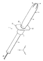
- FIG. 1 is a perspective view of a tampon applicator according to a first embodiment of the present invention. It is a top view of the applicator for tampon shown in FIG. It is a figure which shows the auxiliary
- (A) is a front view
- (B) is a side view. It is a model front view which shows the usage condition of the applicator for tampons shown in FIG. It is a figure which shows the auxiliary
- FIG. 1 is a perspective view showing the entire tampon applicator according to the first embodiment
- FIG. 2 is a plan view of the tampon applicator shown in FIG.
- the tampon applicator 1 has an outer cylinder 2 and an inner cylinder 3.
- the outer cylinder 2 and the inner cylinder 3 have a cylindrical shape having a hollow portion inside.
- the cross-sectional shape of the outer cylinder 2 and the inner cylinder 3 is a perfect circle.
- the outer cylinder 2 and the inner cylinder 3 are entirely formed of a polyolefin-based resin such as polyethylene or polypropylene, or cardboard whose surface is laminated with a polyolefin film.
- the outer cylinder 2 and the inner cylinder 3 are individually molded by injection molding by mixing polyethylene or polypropylene, pigment 1% or more, and lubricant 1% or more.
- the cross-sectional shape of the outer cylinder 2 and the inner cylinder 3 which concerns on this Embodiment is a perfect circle, the cross-sectional shape of the outer cylinder 2 and the inner cylinder 3 should just be a shape which can be easily inserted in a vagina, For example, it may be oval.
- an absorber 4 as a tampon is accommodated in the outer cylinder 2.
- An extraction string 4 a is connected to the absorber 4.
- the take-out string 4 a is inserted through the inner cylinder 3 from the end of the absorber 4, and the insertion end is extracted from the inner cylinder 3.
- the absorbent body 4 can be pulled out from the body by pulling the take-out string 4a during use.
- An opening 8 through which the absorber 4 is pushed out is provided at one end of the outer cylinder 2.
- the opening 8 is formed with a petal body 8a that is deformed outward in the radial direction when the absorber 4 is pushed out.
- the petal body 8a is formed of four divided pieces divided every 90 °.
- the petal body 8a is normally closed at the edge of the opening 8, but when the absorbent body 4 is pushed out by the inner cylinder 3, it is spread and opened by the absorbent body 4. Thereby, the absorber 4 is pushed out from the outer cylinder 2, and the absorber 4 can be inserted in a body.
- the other end of the outer cylinder 2 is provided with a gripping portion 7 that is gripped by a finger when the outer cylinder 2 and the inner cylinder 3 are moved.
- An outer diameter D5 of the gripping portion 7 is smaller than an outer diameter D4 of the outer cylinder main body 9 between the opening 8 and the gripping portion 7.
- the distal end portion of the inner cylinder 3 is inserted into the grip portion 7, and the distal end surface of the inserted inner cylinder 3 faces the absorber 4.
- the end of the outer cylinder body 9 on the gripping part 7 side is narrowed to a diameter substantially equal to that of the gripping part 7, and a protrusion 5 is formed at the outer end.
- the protrusion 5 abuts on an auxiliary gripping member 10 to be described later, and restricts the movement of the auxiliary gripping member 10 so as not to move the auxiliary gripping member 10 to the opening 8 side.
- the auxiliary gripping member 10 abuts on the protrusion 5 of the outer cylinder 2 and the movement of the auxiliary gripping member 10 is restricted.
- the movement of the auxiliary gripping member 10 may be regulated in contact with the outer peripheral surface of the two.
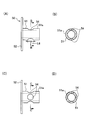
- FIG. 3 is a view showing the auxiliary gripping member 10.
- FIG. 3A is a front view
- FIG. 3B is a left side view of FIG.
- the auxiliary gripping member 10 covers the outer peripheral surface 7a of the gripping portion 7 and extends outward from the outer peripheral surface 11a of the cover portion 11 in the radial direction of the outer cylinder 2 (X direction and Z direction shown in FIG. 1).
- the protruding flange 12 is integrated.
- the auxiliary gripping member 10 has a hole 10a into which the gripping portion 7 is inserted.
- the inner diameter D1 of the hole 10a is smaller than the outer diameter D2 of the protrusion 5.
- the surface 12 a of the flange 12 located at the tip in the insertion direction of the tampon applicator is in contact with the protrusion 5.
- the insertion direction of the tampon applicator is arranged along the longitudinal direction of the tampon applicator (Y direction shown in FIG. 2).
- the contact of the surface 12a of the flange 12 with the protrusion 5 restricts the movement of the auxiliary gripping member 10 toward the distal end side (opening 8 side of the outer cylinder 2) in the insertion direction.
- the inner diameter D1 of the hole 10a may be larger than the outer diameter of the gripping part 7 or the same diameter as the outer diameter of the gripping part 7.
- the auxiliary gripping member 10 is movable with respect to the circumferential direction and the axial direction of the gripping portion 7.
- the inner diameter D1 of the auxiliary gripping member 10 is 11.6 mm
- the outer diameter D4 of the outer cylinder body 9 is 13.4 mm
- the outer diameter D3 of the gripping portion 7 is 10 mm.
- the outer diameter D2 of the protrusion 5 is 13.4 mm.
- the outer diameter D5 of the cover part is 13.2 mm.
- the length L1 in the longitudinal direction Y from the end of the outer cylinder 2 on the opening 8 side to the auxiliary gripping member 10 is 53.05 mm, and the length L2 in the longitudinal direction Y of the auxiliary gripping member 10 is 16 mm.
- the cover part 11 is cylindrical.
- assistant holding member shown to FIG. 3 (A) is a rectangle with four corners curved.
- the width W1 of the collar part 12 shown to FIG. 3 (A) is 16 mm, and the height H1 of the collar part 12 is 32 mm.
- the ratio of the width to the height of the collar portion 12 is 0.41.
- the height H1 of the collar part should just be comprised longer than the outer diameter D5 of the cover part 11 at least.
- the length L4 in the longitudinal direction Y of the grip portion 7 is equal to or less than the length L3 in the longitudinal direction of the cover portion 11.
- the length L3 of the cover portion is 15.2 mm
- the length L4 of the grip portion is 13.5 mm.
- the length of the cover portion 11 is not particularly limited as long as the user can hold it with a finger, and specifically, about 5 mm to 20 mm is preferable.
- the length L5 (thickness of the collar part 12) in the longitudinal direction Y of the collar part 12 is 0.8 mm.
- the length L3 of the cover part 11 By configuring the length L3 of the cover part 11 to be longer than the length L4 of the gripping part 7, the area that can be gripped by the user when the auxiliary gripping member 10 is mounted can be increased. Therefore, when inserting the tampon applicator into the body, the user can firmly hold the grip portion, and the tampon applicator can be inserted in a stable state.
- the auxiliary gripping member 10 is made of polyolefin resin, elastomer, paper, or other material.
- the auxiliary gripping member 10 according to the present embodiment is formed of polyethylene or polypropylene resin.
- FIG. 4 is a schematic cross-sectional view showing how the tampon applicator is used.
- the user presses the auxiliary gripping member 10 in a direction in which the outer cylinder is inserted into the vagina 101 with the tip of the outer cylinder 2 in contact with the vaginal opening 100. Since the surface 12a of the collar portion 12 of the auxiliary gripping member 10 is in contact with the protruding portion 5 of the outer cylinder 2, the auxiliary gripping member 10 is restricted from moving toward the opening with respect to the outer cylinder 2. Therefore, when the user pushes the auxiliary gripping member 10 toward the vagina 101, the outer cylinder 2 is inserted into the vagina.
- the outer cylinder 2 Since the buttocks 12 are arranged on the distal end side of the auxiliary gripping member 10 in the insertion direction (P shown in FIG. 4) of the tampon applicator 1 into the vagina 101, the outer cylinder 2 is inserted to an appropriate position. In the state, the surface 12a of the buttocks 12 is disposed near the vaginal opening. Even if it is going to insert the outer cylinder 2 further in this state, the collar part 12 contacts the user's body. That is, the collar part 12 exhibits the function as a stopper, and the user can grasp that the outer cylinder 2 has been inserted to an appropriate position.
- the buttocks 12 are disposed between the vaginal opening 100 and the finger.
- the width W1 of the heel part 12 is longer than the outer diameter D5 of the cover part 11, the heel part 12 is disposed between the finger having the auxiliary gripping member 10 and the vaginal opening 100, and the body part such as menstrual blood is used. It is possible to prevent the user's finger from getting dirty.
- the user presses the inner cylinder 3 toward the opening 8 of the outer cylinder 2 to thereby absorb the absorbent body from the opening 8 of the outer cylinder 2.
- 4 is pushed out and the absorbent body 4 is placed in a suitable position in the vagina.
- the absorber 4 can be easily arranged at an appropriate position without the user's finger touching the vicinity of the vaginal opening. By arranging the absorber 4 at an appropriate position, the user can feel uncomfortable during use and can feel comfortable using the tampon.
- the auxiliary gripping member 10 includes a cover portion 11 that covers the outer peripheral surface 7a of the gripping portion 7. Since the cover portion 11 and the flange portion 12 are integrated, the auxiliary gripping member for the gripping portion 7 of the outer cylinder 2 is integrated. It becomes easy to keep the angle of 10 constant. Therefore, the outer cylinder 2 can be inserted into the body while the buttocks 12 and the gripping part 7 are maintained at an appropriate angle, and the absorber 4 can be disposed at an appropriate position in the vagina.
- assistant holding member 10 can rotate with respect to the holding part 7, when inserting the outer cylinder 2 in the body in the state which hold
- the outer cylinder 2 can be inserted into the body while maintaining an appropriate angle.
- the tampon The angle and position of the hand holding the applicator 1 for use change.
- the relative angle between the collar 12 and the outer cylinder 2 is changed by following the change in the position and angle of the hand with respect to the tampon applicator 1. be able to. Therefore, even if the angle or position of the hand holding the tampon applicator 1 is changed, the user can insert it smoothly by appropriately applying force to the tampon applicator.
- the auxiliary gripping member 10 in the present embodiment is obtained by injection-molding a thermoplastic resin using a mold.
- the auxiliary gripping member 10 may be molded at the same time as the outer cylinder 2 during injection molding, or may be molded separately and fitted through the integral forming process during the manufacturing process.
- assistant holding member 10 is comprised with respect to the outer cylinder 2 so that attachment or detachment is possible, and it may be comprised so that a user may fit before use.
- the rigidity of the cover part 11 of the auxiliary gripping member 10 is preferably higher than the rigidity of the gripping part 7 of the outer cylinder 2.
- the rigidity of the cover part 11 is low, the cover part 11 is deformed when the user grips it, and the outer cylinder 2 is pressed inward, so that the gap between the outer cylinder 2 and the inner cylinder 3 is reduced. 3 may not be pushed out smoothly.
- the rigidity of the cover part 11 of the auxiliary gripping member 10 is higher than the rigidity of the gripping part 7 of the outer cylinder 2, the deformation of the gripping part 7 of the outer cylinder 2 can be prevented, and the inner cylinder 3 can be pushed out smoothly. It becomes easy.
- the rigidity of the cover portion 11 of the auxiliary gripping member 10 is higher than the rigidity of the gripping portion of the outer cylinder
- assistant holding member 10 thicker than the thickness of a holding part can be illustrated.
- the auxiliary gripping member 40 has a cover part 41 and a flange part 42. On the outer peripheral surface 41 a of the cover portion 41, a protruding portion 44 that protrudes radially outward from the outer peripheral surface of the cover portion is formed.
- the protruding portion 44 is formed on the outer peripheral surface of the cover portion, when the user grips the cover portion, the finger hits the protruding portion 44 and the finger is difficult to slip. Therefore, it is possible to insert the outer cylinder into the body while keeping the buttocks and the gripping part at an appropriate angle, and arrange the absorber at an appropriate position in the vagina.
- the shape of the protruding portion 44 may be a ring shape continuous in the circumferential direction along the circumferential direction of the cylindrical cover portion, or as shown in FIG. Alternatively, it may be an arc shape that is not continuous in the circumferential direction along the circumferential direction of the cylindrical cover portion, or may be a dot shape that is intermittently arranged as shown in FIG. Good.
- the molding method of the protrusion 44 may be mold injection, laser molding, thermoforming, or other methods.
- Examples of the shape of the protrusion 44 include a single letter shape, a symmetry shape, a dot shape, a diamond shape, and a heart shape.
- the height of the protruding portion with respect to the outer peripheral surface of the cover portion is preferably 1 mm or more, and it is desirable to form the entire length of the cover portion 41 as shown in FIG.
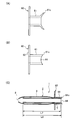
- FIG. 6 (A) and 6 (C) are front views of the auxiliary gripping member 50 according to the third embodiment
- FIG. 6 (B) is a sectional view taken along the line BB of FIG. 6 (A).
- 6D is a cross-sectional view taken along the line CC of FIG. 6C.
- the auxiliary gripping member 50 has a cover part 51 and a flange part 52.
- the outer peripheral surface 51a of the cover part 51 is formed with a recessed part 54 that is recessed radially inward from the outer peripheral surface of the cover part.
- the recessed part 54 is formed in the outer peripheral surface of a cover part, when a user hold
- the length L6 of the recess 54 in the longitudinal direction can be set to a length that allows the finger to be placed, and specifically, 3 mm to 5 mm is preferable.
- two recesses 54 may be formed along the outer peripheral surface of the cover part, or as shown in FIGS. 6 (C) and 6 (D). Four may be formed along the outer peripheral surface of the cover part.
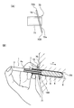
- FIGS. 7A and 7B are side views of the auxiliary gripping member 60 according to the fourth embodiment, and FIG. 7C shows a usage mode of the auxiliary gripping member 60 shown in FIG. 7B. It is the figure shown typically.
- the auxiliary gripping member 60 has a cover part 61 and a flange part 62.
- the end portion 61c of the cover portion 61 in the insertion direction of the tampon applicator is formed with a recess 64 that is recessed from the end portion 61c toward the distal end side in the insertion direction.
- the inner cylinder By forming at least one or more hollow portions 64 at the end portion of the cover portion, the inner cylinder can be pushed inward from the position of the end portion of the cover portion.
- FIG. 7C shows a state in which the tip of the inner cylinder 3 in the insertion direction is in contact with the inner peripheral surface of the outer cylinder 2.
- the length L7 from the tip of the inner cylinder 3 to the recessed portion 64 of the auxiliary gripping member 60 is shorter than the length L8 in the longitudinal direction of the inner cylinder.
- the length L7 from the front end of the inner cylinder 3 to the recessed portion 64 of the auxiliary gripping member 60 is shorter than the length L8 in the longitudinal direction of the inner cylinder, in order to ensure a large area of the cover part, Even when the length in the direction is long, the entire inner cylinder can be pushed into the outer cylinder, and the absorber can be appropriately pushed out by the inner cylinder.
- FIG. 8A is a side view of the auxiliary gripping member 70 according to the fifth embodiment
- FIG. 8B is a diagram schematically illustrating how the auxiliary gripping member 70 is used.
- the auxiliary gripping member 70 according to the fifth embodiment has a cover part 71 and a flange part 72.
- the surface 12 a of the flange portion 12 of the auxiliary gripping member 10 according to the first embodiment is disposed substantially perpendicular to the outer peripheral surface of the cover portion 11.
- the surface 72a of the flange portion 72 of the fifth embodiment is not perpendicular to the outer peripheral surface of the cover portion 71 but is arranged obliquely.
- the collar part 12 of 1st Embodiment is arrange
- the collar part 72 of 5th Embodiment is back in the insertion direction rather than the front-end
- a portion 72S of the outer peripheral edge of the collar portion 72 that is the outer side in the radial direction of the outer cylinder 2 is disposed rearward of the tip of the cover portion 71, but the other portion 72T of the outer peripheral edge of the collar portion 72 is a cover. It is arranged in front of the tip of the portion 71.
- FIG. 8B shows how the tampon applicator 1 is used with the auxiliary gripping member 70 attached to the outer cylinder 2.
- the user's vaginal opening is generally disposed substantially perpendicular to the axial direction of the vagina. Therefore, by arranging the axial direction of the outer cylinder vertically using the tampon applicator in which the flange 12 is arranged substantially perpendicular to the outer peripheral surface of the outer cylinder 2 as in the first embodiment, The surface of the buttocks 12 can be disposed so as to face the vaginal opening.
- the user's vaginal opening is generally arranged obliquely with respect to the axial direction of the vagina.
- the tampon applicator in which the flange portion is disposed substantially perpendicular to the outer peripheral surface of the outer cylinder as in the first embodiment, when the outer cylinder 2 is inserted to an appropriate position, The surface of the buttocks may not be disposed opposite the vaginal opening, and a gap may be formed between the surface of the buttocks and the vaginal opening.
- the tampon applicator according to the fifth embodiment when the tampon applicator is inserted to an appropriate position, as shown in FIG. It can comprise so that it may contact
- the collar portion of the auxiliary gripping member may have an outer shape other than a rectangle in plan view, may be a polygon such as a rectangle or a triangle, or may be a heart shape, a star shape, or an apple shape. It may be oval, teardrop type, or the shape of an animal head or an insect such as a butterfly.
- a medical device tampon can be cutely decorated with the buttocks. Therefore, the depressed feeling of the user's physiology can be relieved and the willingness to use the next time can be improved.
- the decoration effect can be further enhanced by coloring the buttock.
- the color attached to the buttocks is not particularly limited.
- the heart-shaped buttocks can be red or pink, and the bear-head-shaped buttocks can be brown.
- the collar part can be made conspicuous, and handling in a dim place such as a toilet becomes easy.
- the outer peripheral shape of the buttocks is preferably a curved shape.
- the curved shape may be any configuration that does not have a sharp corner, and may include a linear shape in part. Since the outer peripheral shape of the buttock is a curved shape, it is possible to reduce the feel when the user grips the buttock.
- the collar portion of the auxiliary gripping member may not be arranged at the tip of the cover portion in the insertion direction, and may be arranged behind the tip of the cover portion.
- the front end of the cover portion abuts on the outer peripheral surface of the outer cylinder or the protruding portion, and the auxiliary gripping member moves toward the front end side. Is configured to be regulated.
- the auxiliary gripping member includes a cover portion and a collar portion that covers the gripping portion of the outer cylinder, and can provide a tampon applicator that can be used by a user gripping the cover portion and the collar portion.
- the grip portion of the outer cylinder is compared with the case where only the flange portion is attached to the grip portion.
- the position relative to is stabilized. Therefore, it is possible to suppress the positional deviation between the buttocks or the gripping part and the outer cylinder, and the outer cylinder is inserted into the body while maintaining the buttocks or the gripping part at an appropriate angle, and the absorber is placed at an appropriate position in the vagina.
- a tampon applicator that can be placed can be provided.
Landscapes
- Health & Medical Sciences (AREA)
- Epidemiology (AREA)
- Engineering & Computer Science (AREA)
- Biomedical Technology (AREA)
- Heart & Thoracic Surgery (AREA)
- Vascular Medicine (AREA)
- Life Sciences & Earth Sciences (AREA)
- Animal Behavior & Ethology (AREA)
- General Health & Medical Sciences (AREA)
- Public Health (AREA)
- Veterinary Medicine (AREA)
- Absorbent Articles And Supports Therefor (AREA)
Abstract
Description
図1及び図2を参照して、本発明の第1の実施形態に係るタンポン用アプリケータについて説明する。図1は、第1の実施形態に係るタンポン用アプリケータの全体を示す斜視図、図2は、図1に示すタンポン用アプリケータの平面図である。
次いで、図5に基づいて第2の実施形態に係る補助把持部材40について説明する。なお、以下の実施形態の説明においては、第1の実施形態と異なる構成のみ説明し、第1の実施形態と同様の構成については、同符号を用いて説明を省略する。
次いで、図6に基づいて、第3の実施形態に係る補助把持部材50について説明する。図6(A)及び(C)は、第3の実施形態に係る補助把持部材50の正面図であり、図6(B)は、図6(A)のB-B断面の断面図であり、図6(D)は、図6(C)のC-C断面の断面図である。
次いで、図7に基づいて、第4の実施形態に係る補助把持部材60について説明する。図7(A)及び(B)は、第4の実施形態に係る補助把持部材60の側面図であり、図7(C)は、図7(B)に示す補助把持部材60の使用態様を模式的に示した図である。
次いで、図8に基づいて、第5の実施形態に係る補助把持部材70について説明する。図8(A)は、第5の実施形態に係る補助把持部材70の側面図であり、図8(B)は、補助把持部材70の使用態様を模式的に示した図である。
Claims (7)
- 吸収体が内部に収容される外筒と、
前記外筒内に挿入されることにより、前記外筒内の前記吸収体を前記外筒外へ押し出す内筒と、を有し、
前記外筒の一端には、前記吸収体が押し出される開口が形成され、前記外筒の他端には、使用者が把持する把持部が形成されたタンポン用アプリケータであって、
前記外筒の前記把持部の外周面を覆うカバー部と、前記カバー部の外周面から前記外筒の径方向外側に向けて延出する鍔部と、を有する補助把持部材を備える、タンポン用アプリケータ。 - 前記鍔部は、前記タンポン用アプリケータの膣内への挿入方向における前記補助把持部材の先端側に配置されている、請求項1に記載のタンポン用アプリケータ。
- 前記タンポン用アプリケータの長手方向において、前記カバー部の長さは、前記把持部の長さよりも長い、請求項1又は請求項2に記載のタンポン用アプリケータ。
- 前記カバー部の前記外周面には、前記カバー部の外周面から前記径方向外側に突出した突起部が形成されている、請求項1から請求項3のいずれかに記載のタンポン用アプリケータ。
- 前記カバー部の前記外周面には、前記外周面から径方向内側に凹んだ凹み部が形成されている、請求項1から請求項4のいずれかに記載のタンポン用アプリケータ。
- 前記タンポン用アプリケータの膣内への挿入方向における前記カバー部の末端部には、前記末端部から前記挿入方向における先端部側に向かって窪む窪み部が形成されており、
前記挿入方向における前記内筒の先端が前記外筒の内周面に当接した状態で、前記内筒の先端から前記補助把持部材の前記窪み部までの長さは、前記内筒の前記長手方向の長さよりも短い、請求項1から請求項5のいずれかに記載のタンポン用アプリケータ。 - 前記補助把持部材の前記カバー部の剛性は、前記外筒の前記把持部の剛性よりも高い、請求項1から請求項6のいずれかに記載のタンポン用アプリケータ。
Priority Applications (5)
| Application Number | Priority Date | Filing Date | Title |
|---|---|---|---|
| EP12820148.0A EP2737887B1 (en) | 2011-07-29 | 2012-07-26 | Tampon applicator |
| AU2012291212A AU2012291212A1 (en) | 2011-07-29 | 2012-07-26 | Tampon applicator |
| KR1020147001734A KR20140039316A (ko) | 2011-07-29 | 2012-07-26 | 탐폰용 어플리케이터 |
| US14/235,726 US9474656B2 (en) | 2011-07-29 | 2012-07-26 | Tampon applicator |
| CN201280038050.8A CN103717185A (zh) | 2011-07-29 | 2012-07-26 | 止血塞用施放器 |
Applications Claiming Priority (2)
| Application Number | Priority Date | Filing Date | Title |
|---|---|---|---|
| JP2011167807A JP5996170B2 (ja) | 2011-07-29 | 2011-07-29 | タンポン用アプリケータ |
| JP2011-167807 | 2011-07-29 |
Publications (1)
| Publication Number | Publication Date |
|---|---|
| WO2013018655A1 true WO2013018655A1 (ja) | 2013-02-07 |
Family
ID=47629180
Family Applications (1)
| Application Number | Title | Priority Date | Filing Date |
|---|---|---|---|
| PCT/JP2012/068994 Ceased WO2013018655A1 (ja) | 2011-07-29 | 2012-07-26 | タンポン用アプリケータ |
Country Status (9)
| Country | Link |
|---|---|
| US (1) | US9474656B2 (ja) |
| EP (1) | EP2737887B1 (ja) |
| JP (1) | JP5996170B2 (ja) |
| KR (1) | KR20140039316A (ja) |
| CN (1) | CN103717185A (ja) |
| AR (1) | AR087369A1 (ja) |
| AU (1) | AU2012291212A1 (ja) |
| TW (1) | TWI533850B (ja) |
| WO (1) | WO2013018655A1 (ja) |
Cited By (1)
| Publication number | Priority date | Publication date | Assignee | Title |
|---|---|---|---|---|
| WO2016157609A1 (ja) * | 2015-03-30 | 2016-10-06 | オリンパス株式会社 | カプセル放出装置およびカプセル放出システム |
Families Citing this family (3)
| Publication number | Priority date | Publication date | Assignee | Title |
|---|---|---|---|---|
| JP5791310B2 (ja) * | 2011-03-01 | 2015-10-07 | ユニ・チャーム株式会社 | タンポン用アプリケータ |
| MX2020003951A (es) | 2017-10-06 | 2020-08-03 | Essity Hygiene & Health Ab | Aplicador de tampon. |
| US10779997B1 (en) * | 2020-01-17 | 2020-09-22 | Lacey Janell Lund | Tampon insertion device with depth indicator |
Citations (3)
| Publication number | Priority date | Publication date | Assignee | Title |
|---|---|---|---|---|
| JP2003180742A (ja) * | 2001-12-13 | 2003-07-02 | Kao Corp | 生理用タンポンのアプリケータ |
| WO2008090667A1 (ja) * | 2007-01-24 | 2008-07-31 | Uni-Charm Corporation | 生理用タンポン |
| JP2010515520A (ja) * | 2007-01-10 | 2010-05-13 | ザ プロクター アンド ギャンブル カンパニー | アクティブアプリケータ |
Family Cites Families (21)
| Publication number | Priority date | Publication date | Assignee | Title |
|---|---|---|---|---|
| US4125113A (en) * | 1975-01-09 | 1978-11-14 | Kimberly-Clark Corporation | Applicator for inserting hygienic media into body cavities |
| US4048998A (en) * | 1976-02-19 | 1977-09-20 | The Gillette Company | Tampon inserter |
| US4198978A (en) * | 1977-09-29 | 1980-04-22 | The Gillette Company | Adjustable tampon inserter |
| US4447222A (en) * | 1981-08-03 | 1984-05-08 | Sarnt Sartinoranont | Tampon inserter |
| ZA938595B (en) * | 1992-12-23 | 1994-08-05 | Ndm Acquisition Corp | Wound dressing having a cylindrical shape for deep wounds. |
| US5395309A (en) * | 1993-10-08 | 1995-03-07 | Merocel Corporation | Nasal pack applicator |
| US5437628A (en) * | 1993-11-10 | 1995-08-01 | Kimberly-Clark Corporation | Curved tampon applicator having an improved fingergrip |
| JP3217617B2 (ja) | 1994-10-21 | 2001-10-09 | ユニ・チャーム株式会社 | 生理用タンポン |
| US5709652A (en) * | 1995-06-28 | 1998-01-20 | Mcneil-Ppc, Inc. | Tampon applicator tube having apertured finger grip |
| US5817047A (en) * | 1997-03-17 | 1998-10-06 | The Procter & Gamble Company | Tampon and method of making same |
| US6322531B1 (en) * | 1999-06-25 | 2001-11-27 | Mcneil-Ppc, Inc. | Insertable applicator having a pivotal finger grip tab |
| US6572577B1 (en) * | 2000-06-23 | 2003-06-03 | Mcneil-Ppc, Inc. | Applicator for catamenial device having improved gripper end |
| US6786883B2 (en) * | 2002-04-15 | 2004-09-07 | Ronald D. Shippert | Applicator for insertion of cargo into a body cavity |
| US7727208B2 (en) * | 2002-09-12 | 2010-06-01 | Playtex Products, Inc. | Ergonomic tampon applicator |
| US20070021708A1 (en) * | 2005-07-22 | 2007-01-25 | Bertulis Eugenia M | Tampon applicator having a multi-directional rim |
| CA2655082A1 (en) * | 2006-06-12 | 2007-12-21 | Playtex Products, Inc. | Tampon assembly providing proper bodily placement of a pledget |
| CA2659887C (en) * | 2006-08-04 | 2012-10-02 | Playtex Products, Inc. | Tampon applicator fingergrip having one or more flared portions |
| US8062245B2 (en) * | 2007-02-08 | 2011-11-22 | The Procter & Gamble Company | Self-orienting applicator |
| US8075512B2 (en) * | 2007-04-13 | 2011-12-13 | The Procter & Gamble Company | Applicator having an enhanced gripping region |
| US7935098B2 (en) * | 2008-03-31 | 2011-05-03 | Mcneil-Ppc, Inc. | Applicator for intravaginal devices |
| US8529598B2 (en) * | 2009-02-20 | 2013-09-10 | Boston Scientific Scimed, Inc. | Tissue puncture closure device |
-
2011
- 2011-07-29 JP JP2011167807A patent/JP5996170B2/ja not_active Expired - Fee Related
-
2012
- 2012-07-10 TW TW101124782A patent/TWI533850B/zh not_active IP Right Cessation
- 2012-07-26 EP EP12820148.0A patent/EP2737887B1/en not_active Not-in-force
- 2012-07-26 CN CN201280038050.8A patent/CN103717185A/zh active Pending
- 2012-07-26 AU AU2012291212A patent/AU2012291212A1/en not_active Abandoned
- 2012-07-26 US US14/235,726 patent/US9474656B2/en not_active Expired - Fee Related
- 2012-07-26 WO PCT/JP2012/068994 patent/WO2013018655A1/ja not_active Ceased
- 2012-07-26 KR KR1020147001734A patent/KR20140039316A/ko not_active Withdrawn
- 2012-07-27 AR ARP120102752 patent/AR087369A1/es not_active Application Discontinuation
Patent Citations (3)
| Publication number | Priority date | Publication date | Assignee | Title |
|---|---|---|---|---|
| JP2003180742A (ja) * | 2001-12-13 | 2003-07-02 | Kao Corp | 生理用タンポンのアプリケータ |
| JP2010515520A (ja) * | 2007-01-10 | 2010-05-13 | ザ プロクター アンド ギャンブル カンパニー | アクティブアプリケータ |
| WO2008090667A1 (ja) * | 2007-01-24 | 2008-07-31 | Uni-Charm Corporation | 生理用タンポン |
Cited By (2)
| Publication number | Priority date | Publication date | Assignee | Title |
|---|---|---|---|---|
| WO2016157609A1 (ja) * | 2015-03-30 | 2016-10-06 | オリンパス株式会社 | カプセル放出装置およびカプセル放出システム |
| JP6072391B1 (ja) * | 2015-03-30 | 2017-02-01 | オリンパス株式会社 | カプセル放出装置およびカプセル放出システム |
Also Published As
| Publication number | Publication date |
|---|---|
| AR087369A1 (es) | 2014-03-19 |
| EP2737887B1 (en) | 2016-11-02 |
| JP2013031479A (ja) | 2013-02-14 |
| JP5996170B2 (ja) | 2016-09-21 |
| US20140155809A1 (en) | 2014-06-05 |
| EP2737887A1 (en) | 2014-06-04 |
| US9474656B2 (en) | 2016-10-25 |
| KR20140039316A (ko) | 2014-04-01 |
| TW201316964A (zh) | 2013-05-01 |
| CN103717185A (zh) | 2014-04-09 |
| AU2012291212A1 (en) | 2014-02-20 |
| EP2737887A4 (en) | 2015-04-22 |
| TWI533850B (zh) | 2016-05-21 |
Similar Documents
| Publication | Publication Date | Title |
|---|---|---|
| JP5851094B2 (ja) | タンポン用アプリケータ | |
| US9283122B2 (en) | Tampon applicator | |
| JP6043489B2 (ja) | タンポン用アプリケータ | |
| JP5996170B2 (ja) | タンポン用アプリケータ | |
| MXPA03008949A (es) | Aplicador que tiene extremo de agarre mejorado. | |
| JP4249047B2 (ja) | 生理用タンポン | |
| US20090192436A1 (en) | Applicator having plunger with gripping elements | |
| JP6030830B2 (ja) | タンポン用アプリケータ | |
| JP6043566B2 (ja) | タンポン用アプリケータ | |
| JP5653086B2 (ja) | アプリケータ | |
| EP3474801B1 (en) | Package assembly for or with a tampon applicator | |
| CN212186902U (zh) | 棉条纸质套管、棉条纸质导管组及纸质导管式棉条 | |
| EP2786732B1 (en) | Menstrual tampon position-confirming sheet, explanatory leaflet for menstrual tampon, packaging bag for menstrual tampon, and menstrual tampon-storing object | |
| CN112932796A (zh) | 棉条纸质套管、棉条纸质导管组及纸质导管式棉条 | |
| EP4124466A1 (en) | Sanitary sleeve for a handheld item | |
| TWI459932B (zh) | Tampons for tampons |
Legal Events
| Date | Code | Title | Description |
|---|---|---|---|
| 121 | Ep: the epo has been informed by wipo that ep was designated in this application |
Ref document number: 12820148 Country of ref document: EP Kind code of ref document: A1 |
|
| ENP | Entry into the national phase |
Ref document number: 20147001734 Country of ref document: KR Kind code of ref document: A |
|
| REEP | Request for entry into the european phase |
Ref document number: 2012820148 Country of ref document: EP |
|
| WWE | Wipo information: entry into national phase |
Ref document number: 2012820148 Country of ref document: EP |
|
| WWE | Wipo information: entry into national phase |
Ref document number: 14235726 Country of ref document: US |
|
| NENP | Non-entry into the national phase |
Ref country code: DE |
|
| ENP | Entry into the national phase |
Ref document number: 2012291212 Country of ref document: AU Date of ref document: 20120726 Kind code of ref document: A |