WO2013018708A1 - 車両検出装置及び車両検出方法 - Google Patents
車両検出装置及び車両検出方法 Download PDFInfo
- Publication number
- WO2013018708A1 WO2013018708A1 PCT/JP2012/069171 JP2012069171W WO2013018708A1 WO 2013018708 A1 WO2013018708 A1 WO 2013018708A1 JP 2012069171 W JP2012069171 W JP 2012069171W WO 2013018708 A1 WO2013018708 A1 WO 2013018708A1
- Authority
- WO
- WIPO (PCT)
- Prior art keywords
- vehicle
- line segment
- windshield
- vehicle detection
- segment components
- Prior art date
- Legal status (The legal status is an assumption and is not a legal conclusion. Google has not performed a legal analysis and makes no representation as to the accuracy of the status listed.)
- Ceased
Links
Images


Classifications
-
- G—PHYSICS
- G08—SIGNALLING
- G08G—TRAFFIC CONTROL SYSTEMS
- G08G1/00—Traffic control systems for road vehicles
- G08G1/01—Detecting movement of traffic to be counted or controlled
- G08G1/017—Detecting movement of traffic to be counted or controlled identifying vehicles
- G08G1/0175—Detecting movement of traffic to be counted or controlled identifying vehicles by photographing vehicles, e.g. when violating traffic rules
-
- G—PHYSICS
- G01—MEASURING; TESTING
- G01B—MEASURING LENGTH, THICKNESS OR SIMILAR LINEAR DIMENSIONS; MEASURING ANGLES; MEASURING AREAS; MEASURING IRREGULARITIES OF SURFACES OR CONTOURS
- G01B11/00—Measuring arrangements characterised by the use of optical techniques
- G01B11/002—Measuring arrangements characterised by the use of optical techniques for measuring two or more coordinates
-
- G—PHYSICS
- G01—MEASURING; TESTING
- G01C—MEASURING DISTANCES, LEVELS OR BEARINGS; SURVEYING; NAVIGATION; GYROSCOPIC INSTRUMENTS; PHOTOGRAMMETRY OR VIDEOGRAMMETRY
- G01C11/00—Photogrammetry or videogrammetry, e.g. stereogrammetry; Photographic surveying
- G01C11/04—Interpretation of pictures
- G01C11/06—Interpretation of pictures by comparison of two or more pictures of the same area
-
- G—PHYSICS
- G06—COMPUTING OR CALCULATING; COUNTING
- G06T—IMAGE DATA PROCESSING OR GENERATION, IN GENERAL
- G06T7/00—Image analysis
- G06T7/50—Depth or shape recovery
- G06T7/55—Depth or shape recovery from multiple images
- G06T7/593—Depth or shape recovery from multiple images from stereo images
-
- G—PHYSICS
- G06—COMPUTING OR CALCULATING; COUNTING
- G06T—IMAGE DATA PROCESSING OR GENERATION, IN GENERAL
- G06T7/00—Image analysis
- G06T7/70—Determining position or orientation of objects or cameras
- G06T7/73—Determining position or orientation of objects or cameras using feature-based methods
- G06T7/75—Determining position or orientation of objects or cameras using feature-based methods involving models
-
- G—PHYSICS
- G08—SIGNALLING
- G08G—TRAFFIC CONTROL SYSTEMS
- G08G1/00—Traffic control systems for road vehicles
- G08G1/123—Traffic control systems for road vehicles indicating the position of vehicles, e.g. scheduled vehicles; Managing passenger vehicles circulating according to a fixed timetable, e.g. buses, trains, trams
-
- G—PHYSICS
- G06—COMPUTING OR CALCULATING; COUNTING
- G06T—IMAGE DATA PROCESSING OR GENERATION, IN GENERAL
- G06T2207/00—Indexing scheme for image analysis or image enhancement
- G06T2207/10—Image acquisition modality
- G06T2207/10004—Still image; Photographic image
- G06T2207/10012—Stereo images
-
- G—PHYSICS
- G06—COMPUTING OR CALCULATING; COUNTING
- G06T—IMAGE DATA PROCESSING OR GENERATION, IN GENERAL
- G06T2207/00—Indexing scheme for image analysis or image enhancement
- G06T2207/30—Subject of image; Context of image processing
- G06T2207/30236—Traffic on road, railway or crossing
-
- G—PHYSICS
- G06—COMPUTING OR CALCULATING; COUNTING
- G06V—IMAGE OR VIDEO RECOGNITION OR UNDERSTANDING
- G06V10/00—Arrangements for image or video recognition or understanding
- G06V10/20—Image preprocessing
- G06V10/24—Aligning, centring, orientation detection or correction of the image
- G06V10/243—Aligning, centring, orientation detection or correction of the image by compensating for image skew or non-uniform image deformations
-
- G—PHYSICS
- G06—COMPUTING OR CALCULATING; COUNTING
- G06V—IMAGE OR VIDEO RECOGNITION OR UNDERSTANDING
- G06V20/00—Scenes; Scene-specific elements
- G06V20/10—Terrestrial scenes
-
- G—PHYSICS
- G06—COMPUTING OR CALCULATING; COUNTING
- G06V—IMAGE OR VIDEO RECOGNITION OR UNDERSTANDING
- G06V20/00—Scenes; Scene-specific elements
- G06V20/60—Type of objects
- G06V20/64—Three-dimensional [3D] objects
-
- G—PHYSICS
- G06—COMPUTING OR CALCULATING; COUNTING
- G06V—IMAGE OR VIDEO RECOGNITION OR UNDERSTANDING
- G06V2201/00—Indexing scheme relating to image or video recognition or understanding
- G06V2201/08—Detecting or categorising vehicles
Definitions
- Embodiments described herein relate generally to a vehicle detection device and a vehicle detection method.
- the passage of a vehicle is generally detected by a pole sensor (vehicle detection device) of a transmission type and a reflection type using an infrared laser.
- a pole sensor vehicle detection device
- the shape of the vehicle is various, and the length from the vehicle front end detected by the pole sensor to a specific part of the vehicle (for example, the vicinity of the windshield where the vehicle-mounted device is installed) varies from vehicle to vehicle. For this reason, it is difficult to detect a specific part by the pole sensor.
- the pole sensor requires excavation work at the time of installation, and additionally requires equipment for adjusting the positions of the left and right sensors. For this reason, there is a disadvantage that construction and adjustment costs are required. As described above, it is desirable that the pole sensor is replaced with a vehicle detection device as another means.
- the vehicle detection device using the stereo method has a problem in that the feature points that correspond between a plurality of images change each time, and the alignment reference becomes unclear.
- the problem to be solved by the present invention is to provide a vehicle detection device that can define a feature point that corresponds between a plurality of images and can clarify the alignment reference and improve the vehicle detection accuracy.
- the vehicle detection apparatus includes a detection unit that detects a vehicle from a captured image obtained by shooting the vehicle, an extraction unit, and a measurement unit.
- the extraction means extracts a plurality of line segment components indicating boundaries between the specific area of the vehicle and the vehicle body included in the captured image.
- the measuring means measures the position of the vehicle based on coordinate information between the extracted line segment components and shooting position information of the shot image.
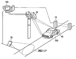
- FIG. 1 is a schematic diagram illustrating a configuration of a vehicle detection system to which the vehicle detection device according to the first embodiment is applied.
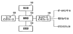
- FIG. 2 is a block diagram illustrating a configuration of the vehicle detection device according to the first embodiment.
- FIG. 3 is a schematic diagram showing the windshield region and its line segment component in the first embodiment.
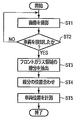
- FIG. 4 is a flowchart for explaining the operation according to the first embodiment.
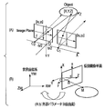
- FIG. 5A is a diagram showing the stereo camera model in the first embodiment
- FIG. 5B is a diagram showing the relationship between the camera coordinate system and the world coordinate system.
- FIG. 6A is a schematic diagram showing a rough approximation of the windshield in the second embodiment
- FIG. 6B is a schematic diagram showing a detailed approximation thereof.
- FIG. 7 is a flowchart for explaining the operation according to the second embodiment.
- FIG. 8 is a diagram for explaining the measurement operation of the vehicle width and the vehicle height by the vehicle detection device according to the third embodiment.
- each embodiment is a configuration in which the windshield region is extracted from the left and right camera images, paying attention to the windshield region (an approximate region in a polygon) of the vehicle. Furthermore, the line segment component that constitutes the windshield region is used as a feature quantity, and by taking correspondence with the left and right gaze features, a stereo view targeting the vehicle is realized, and a highly accurate vehicle detection is realized. is there.
- FIG. 1 is a schematic diagram showing a configuration of a vehicle detection system to which a vehicle detection device 100 according to this embodiment is applied.
- the vehicle detection system includes a pole sensor 10, an electronic camera 20, an ETC (Electronic Toll Collection) system 30, and a vehicle detection device 100.
- ETC Electronic Toll Collection
- the pole sensor 10 detects the vehicle 40 entering the ETC lane using an optical sensor or a tread board, and notifies the vehicle detection device 100 of the detection result.
- the electronic camera (hereinafter simply referred to as camera) 20 is composed of left and right digital cameras that capture images from the left and right directions with respect to the traveling direction of the vehicle 40. That is, in the camera 20, the digital cameras are installed side by side in the left-right direction at the front upper position in the traveling direction of the vehicle 40. Each digital camera travels on the ETC lane at a preset frame rate and captures a moving image of the vehicle 40 passing through the pole sensor 10. Therefore, the camera 20 captures and outputs a plurality of images for the vehicle 40 traveling on the ETC lane.
- a windshield is taken as an example of the specific part of the vehicle 40.
- the camera 20 is installed at a position where an entire view including at least the windshield of the vehicle 40 can be taken. Further, the camera 20 is installed so as to include the windshield and the side surface of the vehicle 40 in the visual field area 200 as a photographing position. in this case.
- the digital cameras of the camera 20 may be arranged side by side along a direction substantially parallel to the longitudinal direction of the upper side and the lower side of the windshield of the vehicle 40. For example, in the ETC lane, the vehicle 40 may enter or leave from an oblique direction with respect to the optical axis of the camera 20.
- the arrangement direction of the left and right digital cameras is orthogonal to the representative line segment component. It may be installed tilted in the direction.
- the camera 20 may be a camera configured to optically obtain left and right captured images of the vehicle 40 with a single lens, instead of the left and right digital cameras.
- the camera 20 may be a camera that can branch images from both directions at the same time using a special lens of one camera.
- this camera has a configuration using a wedge prism polarization method in which, for example, two lenses are provided at a light entrance, and a prism that bends an optical path is disposed inside.
- the camera 20 transmits image data including a time code indicating the shooting time to the vehicle detection device 100.
- the camera 20, the vehicle detection device 100, and the other device (30) have synchronized time information.
- the vehicle detection apparatus 100, and another apparatus operate
- the data may not include a time code indicating the shooting time.
- the ETC system 30 is a system for automatically collecting a toll imposed on the vehicle 40 traveling on a toll road such as an expressway.
- the ETC system 30 acquires information for specifying the passing vehicle 40 by wireless communication with an on-vehicle device for ETC mounted on the vehicle 40.
- the ETC vehicle-mounted device has an antenna for performing wireless communication, and this antenna is installed at a position where the antenna can be seen through the windshield of the vehicle 40. For this reason, the ETC system 30 can perform highly accurate wireless communication with the vehicle-mounted device for ETC by accurately specifying the position of the windshield.
- the vehicle detection device 100 includes a display unit 110, a user interface 120, a storage unit 130, a network interface 140, and a control unit 150.
- the display unit 110 is a display device using an LCD (Liquid Crystal Display) or the like, and displays various information including the operation status of the vehicle detection device 100.
- the user interface 120 is an interface that receives a user instruction from an input device such as a keyboard, a mouse, or a touch panel.
- the storage unit 130 stores the control program and control data of the control unit 150, and includes storage devices such as HDD (hard disk access), RAM (random access memory), ROM (read only memory), and flash memory. It consists of one or a plurality.
- the network interface 140 is connected to a network such as a LAN, and communicates with each of the pole sensor 10, the camera 20, and the ETC system 30 through this network.
- the control unit 150 includes a microprocessor, operates based on a control program and control data stored in the storage unit 130, and is a general controller of the vehicle detection device 100.
- the control unit 150 detects a specific part of the vehicle 40 set in advance by control data from the captured image of the camera 20 and executes a process of specifying the position of the vehicle 40 in the real space.
- the control unit 150 may specify a position of the vehicle 40 and execute a process of predicting a passing time in the real space (passing time of the communication area of the ETC system 30).
- the control unit 150 includes the following functions (f1) to (f4) in order to execute processing for specifying the position of the vehicle 40.
- the function (f1) is a vehicle detection function that detects the entry of the vehicle 40 from the left and right captured images obtained from the camera 20 including the left and right digital cameras.
- the vehicle detection function uses each method of background difference and pattern matching.
- the vehicle detection function of the camera 20 can be omitted because, for example, the object detected by the pole sensor 10 is the vehicle 40 in many cases.
- the function (f2) is a line segment component extraction function for extracting a plurality of line segment components indicating the boundary between the windshield region of the vehicle 40 and the vehicle body included in the captured image for each of the left and right captured images obtained by capturing the vehicle 40. It is. Specifically, for example, with respect to the photographed image shown in FIG. 3A, the line segment component extraction function has a plurality of line segments indicating the boundary between the windshield region and the vehicle body as shown in FIG. This is a function for extracting the components e1 to e6.
- the function (f3) is a polygon approximation function for performing polygon approximation processing for forming a closed loop using some of a plurality of line segment components extracted from the photographed image for each of the left and right photographed images.
- the closed loop corresponding to the windshield region is composed of a combination of a plurality of line segment components e1 to e6 extracted by the line segment component extraction function.
- the line segment component extraction function and polygon approximation function for each captured image can be realized by the method disclosed in, for example, Japanese Patent Publication (Japanese Patent Application No. 2010-208539).
- the function (f4) aligns at least one line segment component of the line segment components e1 to e6 constituting a closed loop for each of the left and right captured images with each other between the left and right captured images. Furthermore, the function (f4) determines the position of the closed loop based on the coordinate information between the aligned line segment components and the shooting position information (the installation position of the camera 20) indicating the shooting position where the left and right shot images are shot. This is a measurement function that measures the position of the vehicle.
- the measurement function of the function (f4) may include a process for aligning all line segment components constituting the closed loop. For example, when there are many curved surfaces of the windshield of the vehicle 40 and it is difficult to determine the representative line segment component (at least one line segment component), processing for matching left and right representative points by collating the entire windshield area It is.
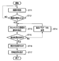
- the vehicle detection device 100 When the power is turned on and started, the vehicle detection device 100 repeatedly executes each process (ST2 to ST5) shown in FIG. 4 until the power is turned off. Each of these processes is executed by the operation of the control unit 150.
- the pole sensor 10 and the camera 20 are also activated. Thereby, the pole sensor 10 starts monitoring the approach of the vehicle 40 to the ETC lane, and notifies the vehicle detection device 100 of the detection result until the power is turned off.
- the camera 20 starts shooting at a predetermined frame rate and transmits the shot image data to the vehicle detection device 100 until the power is turned off (ST1). As a result, the control unit 150 receives image data captured by the camera 20.
- the control unit 150 executes a vehicle detection function for determining whether or not the object detected by the pole sensor 10 is a vehicle in response to a notification from the pole sensor 10 through the network interface 140. That is, the control unit 150 detects the approach of the vehicle 40 based on the results of the background difference process and the pattern matching process from the left and right captured images obtained from the camera 20 (ST2).
- the left and right digital cameras of the camera 20 are installed such that at least a plurality of frames of the windshield region are reflected in the vehicle 40 traveling within the camera angle of view.
- the control unit 150 presets a gaze area for determining the approach of the vehicle on the screen, and detects a video change in the area by a background difference or the like.
- the control unit 150 determines whether or not the detected object is a vehicle by performing a matching process with a vehicle front part pattern (light, front grille, license plate) prepared in advance using the vicinity of the gaze area as a search area. judge. Or you may detect the number plate etc. which are the characteristics of a vehicle.
- control unit 150 When the control unit 150 detects the approach of the vehicle 40, the control unit 150 proceeds to a process of extracting a line segment in the windshield region as described below (YES in ST2, ST3). Note that, when the entry of the vehicle 40 is not detected, the control unit 150 continues the vehicle entry monitoring process again (NO in ST2).
- the control unit 150 extracts image data of a frame shot at a predetermined time from among a plurality of image data transmitted from the camera 20 through the network interface 140.
- the extracted image data is referred to as image data to be processed.
- the predetermined time includes the positional relationship (installation distance) between the installation position of the pole sensor 10 and the camera field of view (imaging range), the vehicle so that image data obtained by capturing a specific part of the vehicle 40 can be extracted. This is determined in consideration of the assumed passing speed of the vehicle.
- the control unit 150 performs preprocessing on the image data to be processed.
- the preprocessing includes noise removal processing for the purpose of improving the S / N ratio.
- the image is sharpened by this noise removal processing.
- the preprocessing includes filtering.
- the preprocessing includes a video distortion correction process.
- the control unit 150 applies a technique such as a Hough transform from the image data to be processed on which the pre-processing has been performed, and a plurality of line segment components e1 indicating the boundary between the windshield region of the vehicle 40 and the vehicle body .About.e6 are extracted (ST3). That is, the control unit 150 extracts a plurality of line segment components e1 to e6 indicating the boundary included in the photographed image for each of the left and right photographed images in which the entry of the vehicle 40 is detected.
- a technique such as a Hough transform from the image data to be processed on which the pre-processing has been performed
- step ST3 when the vehicle 40 is photographed from above, for example, eight line segment components based on the horizontal and vertical directions in the video are extracted. Thereby, many line segment components including a windshield boundary part are extracted. As for the windshield, it is considered that it is difficult to extract with one line segment component because the periphery of the wiper is often curved. For this reason, generally, the process which approximates the shape of a windshield is possible by extracting with the polygon or broken line which combined the some line segment component. Further, for example, when a circle is approximated by a line segment component, a process of approximating it by an inscribed regular octagon is possible. The error in this case corresponds to the difference in area between the circle and the inscribed regular octagon, but is considered to be acceptable as a practical design error.
- control unit 150 performs Hough transform processing on the image data to be processed and the image data of the preceding and succeeding frames, and extracts temporally continuous line segment components from each video. Further, the control unit 150 performs a geometric variation prediction accompanying the movement of the vehicle 40 from these line segment components so as to obtain a line segment component at a predetermined time (the shooting time of the image data to be processed). Also good. As described above, by using a plurality of frames of image data, the extraction accuracy can be increased.
- the control unit 150 For each of the left and right captured images, the control unit 150 performs approximation processing of polygons forming a closed loop using some of the plurality of line segment components extracted in the process of step ST3, and selects a windshield region candidate. Generate.
- the elements extracted from the image by the polygon approximation process are the windshield area, the shadow area reflected in the windshield, the reflective area where the sun is reflected, the pillar that is part of the vehicle, the driver's seat and the passenger seat. There is a window glass. Actually, a closed loop having a complicated shape is generated by a plurality of line segment components.
- the windshield region can be approximated to a rectangle if it is the simplest, but depending on the shape of the windshield, it is approximated to a shape including a curve. Even if it is a simple shape, when it is taken from the lateral direction of the vehicle, depth is generated on the left and right sides of the windshield, and asymmetry appears.
- control unit 150 evaluates a plurality of closed loops generated by the polygon approximation process using an evaluation function, and narrows down candidates to those that accurately approximate the windshield region.
- the above evaluation may be performed after complementarily approximating the missing portion with the line segment component.
- one of the pillars may be hidden by the windshield. In such a case, a closed loop is completed by complementing the line segment component of the edge of the windshield on the pillar side that has been hidden.
- various pillar patterns are stored in the storage unit 130 in advance, and a plurality of windshield region candidates are stored in association with each pattern. Then, a closed loop similar to a pillar is detected from the polygon approximation process, and a pillar is detected by pattern matching between the detected closed loop and information stored in the storage unit 130, and is associated with the detected pillar. You may make it obtain the candidate of a windshield area
- the control unit 150 performs a plurality of different evaluations on the windshield region candidates obtained in this way, and obtains the total score of each evaluation.
- a plurality of evaluation methods there is a first method for scoring in consideration of the position and size of the windshield on the image.
- the control unit 150 selects an optimal windshield region from the total score thus obtained. Further, the control unit 150 inspects the positional relationship between the selected windshield area and the front mask part (light, grille, number) included in the image data to be processed, and thus contradicts (for example, the windshield area and the front windshield area). It is confirmed whether there is a large displacement in the horizontal direction of the mask portion. When there is a contradiction, the same inspection is performed for the windshield region with the next highest score total value.
- the position of the vehicle front mask portion is obtained by pattern matching of elements constituting the front mask portion.
- the controller 150 aligns at least one line segment component between the left and right captured images. (ST4). That is, the control unit 150 aligns at least one line segment component of the line segment components constituting a closed loop for each captured image of the processing target image data between the left and right captured images.
- control unit 150 measures the position of the closed loop as the position of the vehicle 40 based on the coordinate information between the aligned line segment components and the shooting information indicating the shooting positions where the left and right shot images are shot ( ST5).
- control unit 150 uses the world coordinate system (ETC lane) from the camera coordinates (coordinates of the virtual image plane) obtained by taking the difference of the coordinate information.
- the position of the line segment component in the windshield region is calculated by performing conversion to the position in the real space above. This calculated position corresponds to the position of the vehicle to be measured in step ST5.
- reference symbols C 1 and C 2 shown in FIG. 5A indicate the shooting positions of the left and right cameras in the camera coordinate system (the X axis of the shooting plane coordinate system and the center point of the left and right cameras of the camera 20). , Points of intersection with the optical axes of the left and right cameras).
- the left and right cameras are two cameras having the same specification and are installed in parallel equiposition to each other. Therefore, the arrangement is such that the optical surfaces of the two cameras are parallel and the imaging surfaces are matched, and further, the horizontal axes of the imaging surfaces are also matched.
- a symbol b indicates an interval between the left and right cameras.
- Reference symbol f indicates a focal length.
- Object [X, Y, Z] is the coordinates of the corresponding point in the camera coordinate system, and has the following relationship.
- symbols R and t shown in FIG. 5B are external parameters for associating camera coordinates with world coordinates.
- a symbol R indicates a rotation matrix.
- the symbol t indicates a translation vector.
- the control unit 150 notifies the ETC system 30 of the vehicle position (coordinates) measured in step ST5 through the network interface 140.
- the ETC system 30 transmits and receives radio signals to and from the antenna of the on-board device for ETC mounted on the windshield based on the position (coordinates) of the vehicle 40 and the assumed passing speed of the vehicle 40.
- the control unit 150 uses at least one of the line segment components that form a closed loop using a plurality of line segment components indicating the boundary between the windshield region of the vehicle 40 and the vehicle body.
- the line segment components are aligned with each other between the left and right captured images.
- a highly accurate three-dimensional measurement of the vehicle 40 can be realized by extracting the line segment component of the vehicle windshield region boundary portion from the left and right camera images and taking the corresponding relationship between the representative line segment components.
- the position and distance from the on-vehicle device to be communicated can be accurately extracted.
- information corresponding to the vehicle width and height can be determined a priori from the position information of the windshield.
- the control unit 150 extracts a plurality of line segment components constituting the video of the vehicle from the image data obtained by capturing the vehicle, and uses these line segment components to generate a closed loop. Executes square approximation. As a result, the control unit 150 generates a plurality of candidate regions of the specific part (for example, the windshield) of the vehicle 40, and performs a plurality of different evaluations on the candidates to specify the region of the most likely specific part of the vehicle. To do. Therefore, if the specific part of the target vehicle 40 is shown, the specific part can be detected by image processing, so that the degree of freedom of installation of the camera 20 is high and high detection accuracy can be obtained.
- FIGS. 6 and 7 are diagrams for explaining the second embodiment.
- the vehicle detection device 100 and the vehicle detection system according to this embodiment are the same as those in the first embodiment described with reference to FIGS.
- control unit 150 is configured to include a re-execution function (f2-1) in the line segment component extraction function (f2) for extracting the line segment component of the windshield region.
- the re-execution function (f2-1) classifies the plurality of extracted line segment components for each direction, and extracts a plurality of line segment components based on the number and length of the line segment components for each direction. This is a function to re-execute. That is, as shown in FIGS. 6A and 6B, the re-execution function (f2-1) increases the number of the line segment components to shorten the length. And the process of extracting the plurality of line segment components based on the changed parameter is re-executed.
- the extraction rate of components can be improved.
- the extraction rate of the line segment component can be determined based on the extraction result (number and length of line segment components for each direction). Further, the extraction rate of the line segment component can be calculated as a ratio of the actual extraction result to the extraction result assumed in advance with respect to the number and length of the line segment components in each direction.
- the re-execution function (f2-1) reduces the number of line segment components and lengthens the length when the size of the windshield region is larger than the reference size.
- the re-execution function (f2-1) increases the number of line segment components and shortens the length when the size of the windshield area is equal to or smaller than the reference size.
- a configuration including a function of changing parameters at the time of line segment extraction may be used.
- the windshield will depend on the resolution of the windshield being shot.
- a process for changing the resolution of the imaging target may be executed so that a rough approximation process is executed for a high-resolution camera and a detailed approximation process is executed for a low-resolution camera.
- the distinction between the large vehicle and the small vehicle is performed by extracting the headlight region of the vehicle 40 by, for example, labeling processing on the image data to be processed after the preprocessing is performed, and the extracted region indicates It can be estimated from the left and right headlight positions and intervals.
- the camera 20 transmits the captured image data to the vehicle detection device 100 (ST11).
- the control unit 150 of the vehicle detection apparatus 100 receives image data captured by the camera 20.
- Control unit 150 executes the vehicle detection function to detect entry of vehicle 40 (YES in ST12).
- the control unit 150 extracts a plurality of line segment components indicating the boundary between the windshield region of the vehicle 40 and the vehicle body (ST13). If control unit 150 does not detect the entry of vehicle 40, control unit 150 continues the vehicle entry monitoring process again (NO in ST12).
- control unit 150 classifies the extracted line segment components for each direction, and determines whether or not the extraction result is good based on the number and length of the line segment components for each direction (ST15). ). This determination is made based on whether or not the extraction rate of the line segment component is higher than a predetermined extraction rate.
- control unit 150 changes the parameters at the time of line segment extraction so as to shorten the length by increasing the number of the line segment components (NO in ST15, ST14). Based on the changed parameter, control unit 150 re-executes the process of extracting the plurality of line segment components (ST13).
- control unit 150 approximates the polygon that forms the closed loop using some of the plurality of line segment components extracted for each of the left and right captured images, as described above. To generate windshield region candidates. Subsequently, as described above, the control unit 150 executes processing for aligning at least one line segment component between the left and right captured images (ST16). Further, control unit 150 measures and estimates the position of vehicle 40 as described above (ST17).
- the control unit 150 of the vehicle detection device 100 changes the parameters at the time of line segment extraction based on the number and length of the line segment components for each extracted direction, A re-execution function (f2-1) for re-executing the process of extracting components is included.
- a re-execution function (f2-1) for re-executing the process of extracting components is included.
- the line segment component extraction parameter is changed according to the size of the windshield region, and the process of extracting the line segment component is executed again.
- a reliable extraction of minutes can be achieved.
- this embodiment uses the license plate rectangle detection information detected when entering the vehicle when the main line segment component cannot be extracted even if the processing parameters are changed and the detection of the windshield region is attempted multiple times.
- the configuration may be such that the process of associating the information on the four sides is executed.
- the re-execution function (f2-1) of the control unit 150 includes a first line segment component extraction function (f2-1-1) that extracts a plurality of line segment components constituting the windshield region of the vehicle,
- the second line segment component extracting function (f2-1-2) for extracting a plurality of line segment components constituting the rectangular region of the license plate frame may be used.
- the polygon approximation function (f3) of the control unit 150 can form a closed loop based on the line segment component extracted by the first line segment component extraction function (f2-1-1). If not, the polygon approximation process can be executed using each line segment component extracted by the second line segment extraction function (f2-1-2).
- the second line segment component extraction function (f2-1-2) extracts the headlight region of the vehicle, for example, by labeling the image of the pre-processed image data to be processed.
- a rectangular shape similar to the license plate may be extracted from the range estimated from the position.
- the license plate is present at the center between the left and right headlights and below the line connecting them.
- FIG. 8 is a diagram for explaining the third embodiment.
- the vehicle detection device 100 and the vehicle detection system according to this embodiment are the same as those in the first embodiment described with reference to FIGS.
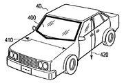
- the vehicle detection device 100 of the present embodiment has a configuration for calculating a vehicle width 410 and a vehicle height 420 of the vehicle 40.
- the control unit 150 includes a vehicle height calculation function (f4-1) for calculating the vehicle height 420 and a vehicle width calculation function for calculating the vehicle width 410 in the measurement function (f4) for measuring the vehicle position.
- the configuration includes at least one of (f4-2).
- the vehicle height calculation function (f4-1) is based on the coordinate information between the line segment components used in the measurement function (f4), and the height of the upper side of the windshield region 400 of the vehicle 40. Is calculated as the vehicle height 420.
- the vehicle width calculation function (f4-2) calculates the length of the bottom side of the windshield region 400 of the vehicle 40 as the vehicle width 410 based on the coordinate information.
- the vehicle height calculation function (f4-1) obtains line segment component information (coordinate information between line segment components) that associates the left and right cameras with respect to the line segment components constituting the windshield region 400.
- the control unit 150 uses the vehicle height calculation function (f4-1) to check the front glass on the left and right side portions of the vehicle.
- the coordinate information of both end points e1 and e2 of the line segment component corresponding to the upper side is calculated. Accordingly, the control unit 150 performs line segment component matching corresponding to the upper side of the windshield based on the correspondence relationship between the two coordinates, and calculates the height 420 from the upper side of the windshield 400 as shown in FIG. .
- the vehicle height calculation function (f4-1) changes the configuration of the camera parameters and directly obtains the correspondence between the coordinate information differences (e1-e2) of the end points e1, e2 on the upper side of the windshield. May calculate the height of the upper side of the windshield.
- the control unit 150 collates line segment components corresponding to the bottom of the windshield based on the correspondence relationship between the two coordinates, and calculates the distance
- the vehicle width calculation function (f4-2) directly changes the coordinate information difference (e6-e5), (e5-e4), (e4-e3) of the lower part of the windshield by changing the configuration of the camera parameters.
- the distance (e6-e5) + (e5-e4) + (e4-e3) of the end point of the lower side of the windshield may be calculated.
- a process of calculating at least one of the vehicle height 420 or the vehicle width 410 is added to the process of step ST5 shown in FIG.
- control unit 150 executes the processes of steps ST1 to ST5 shown in FIG.
- the control unit 150 converts the coordinate information between the line segment components aligned in the process of step ST4 and the shooting position information (camera installation information) indicating the shooting positions where the left and right shot images are shot. Based on this, the position of the closed loop is measured as the vehicle position (ST5).
- the control unit 150 uses the vehicle height calculation function (f4-1) based on the coordinate information of the line segment components aligned in the process of step ST4, as shown in FIG.
- the height of the upper side of the area 400 is calculated as the vehicle height 420.
- the control unit 150 uses the vehicle width calculation function (f4-2) based on the coordinate information of the line segment components aligned in the process of step ST4, as shown in FIG. Is calculated as the vehicle width 410.
- the control unit 150 may be configured to execute either the vehicle height calculation function (f4-1) or the vehicle width calculation function (f4-2).
- the control unit 150 notifies the ETC system 30 of the vehicle position (coordinates), the vehicle height 420 and / or the vehicle width 410 measured in the process of step ST5 through the network interface 140.
- the ETC system 30 transmits and receives radio signals to and from the antenna of the on-board device for ETC mounted on the windshield based on the position (coordinates) of the vehicle 40 and the assumed passing speed of the vehicle 40. Further, the ETC system 30 can acquire additional information on the vehicle height 420 and / or the vehicle width 410 and calculate, for example, statistics of the size of the vehicle passing through the ETC lane.
- the height of the upper side of the windshield region 400 of the vehicle 40 can be calculated as the vehicle height 420 based on the coordinate information. Further, the length of the bottom side of the windshield region 400 of the vehicle 40 can be calculated as the vehicle width 410 based on the coordinate information. Therefore, in addition to the effects of the first or second embodiment described above, additional information on the vehicle height 420 and / or the vehicle width 410 can be estimated.
- a configuration in which at least one line segment component among a plurality of line segment components indicating a boundary between a windshield region of a vehicle and a vehicle body is aligned with each other between left and right captured images is aligned with each other between left and right captured images.
- the storage medium can store a program and can be read by a computer
- the storage format may be any form.
- an OS operating system
- MW middleware
- database management software network software
- the storage medium in each embodiment is not limited to a medium independent of a computer, but also includes a storage medium in which a program transmitted via a LAN, the Internet, or the like is downloaded and stored or temporarily stored.
- the number of storage media is not limited to one, and the case where the processing in each of the above embodiments is executed from a plurality of media is also included in the storage media in the present invention, and the media configuration may be any configuration.
- the computer in each embodiment executes each process in each of the above embodiments based on a program stored in a storage medium, and a single device such as a personal computer or a plurality of devices are connected to a network. Any configuration of the system or the like may be used.
- the computer in each embodiment is not limited to a personal computer, and includes an arithmetic processing device, a microcomputer, and the like included in an information processing device, and is a generic term for devices and devices that can realize the functions of the present invention by a program. Yes.
Landscapes
- Engineering & Computer Science (AREA)
- Physics & Mathematics (AREA)
- General Physics & Mathematics (AREA)
- Computer Vision & Pattern Recognition (AREA)
- Theoretical Computer Science (AREA)
- Radar, Positioning & Navigation (AREA)
- Remote Sensing (AREA)
- Multimedia (AREA)
- Image Analysis (AREA)
- Traffic Control Systems (AREA)
- Image Processing (AREA)
- Length Measuring Devices By Optical Means (AREA)
Abstract
実施形態の車両検出装置は、車両を撮影した撮影画像から車両を検知するコントローラを具備する。前記コントローラは、前記撮影画像に含まれる前記車両の特定領域と車体との境界を示す複数の線分成分を抽出する。さらに、前記コントローラは、前記抽出された線分成分間の座標情報と前記撮影画像の撮影位置情報とに基づいて前記車両の位置を計測する。
Description
本発明の実施形態は、車両検出装置及び車両検出方法に関する。
例えば高速道路の料金所などでは、一般に、赤外線レーザーを用いた透過型及び反射型と呼ばれる方式のポールセンサ(車両検出装置)によって車両の通過を検出する。
しかしながら、車両の形状は多種多様であり、ポールセンサによって検出される車両先端部から、車両の特定部位(例えば、車載器が設置されるフロントガラス近辺)までの長さが車両毎に異なる。このため、ポールセンサによる特定部位の検出は困難である。
また、ポールセンサは、設置時に掘削工事が必要であることに加え、左右のセンサの位置を調整する設備が別途必要である。このため、工事・調整コストがかかるという不都合がある。以上により、ポールセンサは、別の手段の車両検知装置に代替されることが望ましい。
一方、カメラを用いた車両検出装置であれば、既設のポールセンサを利用することにより車両が画角に映る条件を比較的簡単に確保することが可能である。また、カメラは、近年、値段が下がってきており、比較的安価に入手可能となっている。従って、カメラを用いた車両検出装置を実現することが好ましい。
ここで、複数のカメラを用いたステレオ方式による車両検出装置を検討する。一般に、車両の特徴点は車両の形状や見え方によって異なる。このため、ステレオ方式の場合、複数のカメラによる複数の映像間で対応をとる特徴点が都度変わってしまい、位置合わせ基準が不鮮明となる。
以上説明したように、ステレオ方式による車両検出装置は、複数の映像間で対応をとる特徴点が都度変わってしまい、位置合わせ基準が不鮮明となる不都合がある。
本発明が解決しようとする課題は、複数の映像間で対応をとる特徴点を定めて位置合わせ基準を鮮明にでき、車両の検出精度を向上し得る車両検出装置を提供することである。
実施形態の車両検出装置は、車両を撮影した撮影画像から車両を検知する検知手段と、抽出手段と、計測手段とを具備する。前記抽出手段は、前記撮影画像に含まれる前記車両の特定領域と車体との境界を示す複数の線分成分を抽出する。前記計測手段は、前記抽出された線分成分間の座標情報と前記撮影画像の撮影位置情報とに基づいて前記車両の位置を計測する。
以下図面を参照して、各実施形態について説明する。
各実施形態に共通する事項は、車両のフロントガラス領域(多角形での近似領域)に着目し、左右のカメラ映像よりフロントガラス領域を抽出する構成である。さらに、当該フロントガラス領域を構成する線分成分を特徴量として、左右の注視特徴との対応をとることにより、車両を対象とするステレオ視を実現し、高精度な車両検知を実現する構成である。
[第1の実施形態]
図1は本実施形態に係る車両検出装置100を適用した車両検出システムの構成を示す模式図である。図1に示すように、この車両検出システムは、ポールセンサ10と、電子カメラ20と、ETC(Electronic Toll Collection)システム30と、車両検出装置100とを備えている。
図1は本実施形態に係る車両検出装置100を適用した車両検出システムの構成を示す模式図である。図1に示すように、この車両検出システムは、ポールセンサ10と、電子カメラ20と、ETC(Electronic Toll Collection)システム30と、車両検出装置100とを備えている。
ポールセンサ10は、光センサや踏板を用いて、ETCレーンに進入する車両40を検出し、その検出結果を車両検出装置100に通知する。
電子カメラ(以下単にカメラ)20は、車両40の走行方向に対して左右方向から撮影する左右のディジタルカメラから構成されている。即ち、カメラ20は、各ディジタルカメラが車両40の走行方向の前上方の位置に左右方向に並べて設置されている。各ディジタルカメラは予め設定したフレームレートで、ETCレーンを走行し、ポールセンサ10を通過してくる車両40の動画像を撮影する。従って、カメラ20は、ETCレーンを走行する車両40について、複数の画像を撮影し出力する。
なお、以下の説明では、車両40の特定部位として、フロントガラスを例に挙げる。このため、カメラ20は、少なくとも車両40のフロントガラスを含む全景が撮影できる位置に設置される。また、カメラ20は撮影位置として、車両40のフロントガラス及び側面を視野エリア200に含むように設置される。この場合.カメラ20の各ディジタルカメラは、車両40のフロントガラスの上辺及び下辺の長手方向に略平行する方向に沿って並べて配置されてもよい。例えば、ETCレーンにおいて、車両40がカメラ20の光軸に対して斜め方向より進入または退出する場合がある。このような場合には、車両40のフロントガラス領域と車体との境界を示す線分成分が一様に傾いてしまうため、左右の各ディジタルカメラの並び方向を、その代表線分成分に直交する方向に傾けて設置されてもよい。
なお、カメラ20としては、左右のディジタルカメラに代えて、1枚のレンズで光学的に車両40の左右の撮影画像を得る構成のカメラでもよい。例えば、カメラ20として1台のカメラの特殊なレンズにより、同時に双方向からの映像を一度に分岐できる構成のカメラでもよい。具体的には、このカメラは、例えば光の入り口には2つのレンズを備え、内部には光路を曲げるプリズムが配置されたウェッジ(wedge)プリズム偏光方式を用いた構成である。
カメラ20は、撮影時刻を示すタイムコードを含む画像データを車両検出装置100に伝送する。カメラ20、車両検出装置100及び他の装置(30)は、同期した時刻情報を有する。なお、カメラ20、車両検出装置100及び他の装置が同期して動作して、車両検出装置100及び他の装置がカメラ20の撮影時刻を認識できる構成であれば、カメラ20から出力される画像データには、撮影時刻を示すタイムコードが含まれなくてもよい。
ETCシステム30は、高速道路などの有料道路を走行する車両40に対して課せられる通行料金を自動的に徴収するためのシステムである。ETCシステム30は、車両40に搭載されるETC用車載器との無線通信により、通過する車両40を特定するための情報を取得する。なお、一般的に、ETC用車載器は、無線通信を行うためのアンテナを有し、このアンテナが車両40のフロントガラスを介して視認できる位置に設置されている。このため、ETCシステム30は、フロントガラスの位置が正確に特定されることで、ETC用車載器と精度の高い無線通信を行うことができる。
次に、図2に示すように、車両検出装置100は、表示部110と、ユーザインタフェース120と、記憶部130と、ネットワークインタフェース140と、制御部150とを備える。
表示部110は、LCD(Liquid Crystal Display)などを用いたディスプレイ装置であって、当該車両検出装置100の運用状況を初めとする種々の情報を表示する。ユーザインタフェース120は、キーボード、マウス、タッチパネルなどの入力装置からユーザの指示を受け付けるインタフェースである。記憶部130は、制御部150の制御プログラムや制御データを記憶するものであって、HDD(hard disk drive)、RAM(random access memory)、ROM(read only memory)、フラッシュメモリなどの記憶デバイスの1つ、又は複数個からなる。ネットワークインタフェース140は、LANなどのネットワークに接続されて、このネットワークを通じて、ポールセンサ10、カメラ20およびETCシステム30のそれぞれと通信する。
制御部150はマイクロプロセッサを有し、記憶部130が記憶する制御プログラムや制御データに基づいて動作し、当該車両検出装置100の統括的コントローラである。制御部150は、予め制御データで設定される車両40の特定部位をカメラ20の撮影画像から検出し、実空間上における車両40の位置を特定する処理を実行する。なお、制御部150は、車両40の位置を特定すると共に、実空間上における通過時刻(ETCシステム30の通信エリアの通過時刻)を予測する処理を実行してもよい。
制御部150は、車両40の位置を特定する処理を実行するために、以下の各機能(f1)~(f4)を備えている。
機能(f1)は、左右のディジタルカメラからなるカメラ20から得られた左右の撮影画像から車両40の進入を検知する車両検知機能である。なお、車両検知機能は、背景差分およびパターン照合の各方法を用いている。但し、カメラ20の車両検知機能は、例えば多くの場合にはポールセンサ10が検出した対象が車両40であることから、省略可能となっている。
機能(f2)は、車両40を撮影した左右の撮影画像毎に、当該撮影画像に含まれる車両40のフロントガラス領域と車体との境界を示す複数の線分成分を抽出する線分成分抽出機能である。具体的には、例えば図3(A)に示す撮影画像に対して、線分成分抽出機能は、図3(B)に示すように、フロントガラス領域と車体との境界を示す複数の線分成分e1~e6を抽出する機能である。
機能(f3)は、左右の撮影画像毎に、当該撮影画像から抽出された複数の線分成分の幾つかを用いて閉ループを構成する多角形近似処理を行う多角形近似機能である。補足すると、フロントガラス領域に相当する閉ループは、線分成分抽出機能により抽出された複数の線分成分e1~e6の組合せで構成されている。また、撮影画像毎の線分成分抽出機能及び多角形近似機能については、例えば日本国特許公報(特願2010-208539)により開示されている方法により実現可能である。
機能(f4)は、左右の撮影画像毎に閉ループを構成する線分成分e1~e6のうちの少なくとも1つの線分成分を当該左右の撮影画像間で互いに位置合わせする。さらに、機能(f4)は、当該位置合わせした線分成分間の座標情報と、左右の撮影画像を撮影した撮影位置を示す撮影位置情報(カメラ20の設置位置)とに基づいて、閉ループの位置を車両の位置として計測する計測機能である。
なお、機能(f4)の計測機能は、閉ループを構成する全ての線分成分を位置合わせする処理を含むものでもよい。例えば、車両40のフロントガラスの曲面が多く、代表線分成分(少なくとも1つの線分成分)を決定することが難しい場合については、フロントガラス領域全体で照合して左右代表点の対応をとる処理である。
次に、図4のフローチャートを参照して、本実施形態の車両検出装置100を適用した車両検出システムの動作を説明する。
車両検出装置100は、電源が投入されて起動されると、図4に示す各処理(ST2~ST5)を電源がオフするまで繰り返し実行する。なお、これらの各処理は、制御部150の動作により実行される。
車両検出装置100の起動に先立って、ポールセンサ10およびカメラ20も起動される。これにより、ポールセンサ10は、ETCレーンへの車両40の進入の監視を開始し、電源がオフするまで、検出結果を車両検出装置100に通知する。カメラ20は、所定のフレームレートによる撮影を開始し、電源がオフするまで、撮影した画像データを車両検出装置100に伝送する(ST1)。これにより、制御部150は、カメラ20により撮影された画像データを受信する。
制御部150は、ネットワークインタフェース140を通じたポールセンサ10からの通知に応じて、ポールセンサ10が検出した対象が車両か否かを判定する車両検知機能を実行する。即ち、制御部150は、カメラ20から得られた左右の撮影画像から背景差分処理及びパターン照合処理の結果に基づいて、車両40の進入を検知する(ST2)。
ここで、カメラ20の左右のディジタルカメラは、カメラ画角内を走行する車両40について、少なくとも複数フレームのフロントガラス領域が映るよう設置されている。制御部150は、画面上に車両の進入を判定する注視領域を予め設定し、その領域内での映像変化を背景差分などで検出する。制御部150は、検出した対象が車両か否かについては、注視領域近傍を探索領域とし、予め用意された車両のフロント部パターン(ライト、フロントグリル、ナンバープレート)とのマッチング処理を行うことにより判定する。または、車両の特徴であるナンバープレート等を検出してもよい。
制御部150は、車両40の進入を検知した場合には、下記のようなフロントガラス領域の線分を抽出する処理に移行する(ST2のYES、ST3)。なお、制御部150は、車両40の進入を検知しなかった場合には、再び車両の進入の監視処理を続行する(ST2のNO)。
制御部150は、ネットワークインタフェース140を通じて、カメラ20から伝送される複数の画像データのうち、所定の時刻に撮影されたフレームの画像データを抽出する。以下、この抽出した画像データを処理対象の画像データと称する。なお、上記所定の時刻は、車両40の特定部位が撮影された画像データが抽出できるように、ポールセンサ10の設置位置とカメラ20のカメラ視野(撮影範囲)の位置関係(設置距離)、車両の想定通過速度などを考慮して決定される。
制御部150は、処理対象の画像データに対して前処理を実行する。具体的には、前処理には、S/N比を向上させる目的でノイズ除去処理が含まれる。このノイズ除去処理のより、画像の鮮鋭化が実現される。また、映像のコントラストを向上させるために、前処理にはフィルタリングが含まれる。さらに、画像の補正を目的として、前処理には映像歪の修正処理が含まれる。
制御部150は、前処理を実行した処理対象の画像データから、ハフ変換(Hough transform)などの手法を適用して、車両40のフロントガラス領域と車体との境界を示す複数の線分成分e1~e6を抽出する(ST3)。即ち、制御部150は、車両40の進入が検知された左右の撮影画像毎に、当該撮影画像に含まれる前記境界を示す複数の線分成分e1~e6を抽出する。
ステップST3の具体的な抽出アルゴリズムとしては、車両40を上方から撮影する場合、例えば映像中の水平および垂直方向を基本とした8方向の線分成分の抽出を行う。これにより、フロントガラス境界部分を含む線分成分が多数抽出されることになる。フロントガラスについては、ワイパー周り等は曲線となっている場合が多いため、1つの線分成分で抽出するのは難しいと考えられる。このため、一般的には、複数の線分成分を組み合わせた多角形もしくは折れ線で抽出することで、フロントガラスの形状を近似する処理が可能である。また例えば、円を線分成分で近似する場合は、内接正八角形にて近似する処理が可能である。この場合の誤差は、円と内接正八角形の面積の差に相当するが、実用設計上の誤差としては許容可能と考えられる。
なお、制御部150は、処理対象の画像データと、その前後のフレームの画像データに対してハフ変換の処理を実行して、各映像から時間的に連続する線分成分を抽出する。さらに、制御部150は、これらの線分成分から車両40の移動に伴う幾何学的な変動予測を実行し、所定の時刻(処理対象の画像データの撮影時刻)における線分成分を得るようにしてもよい。このように複数フレームの画像データを用いることで、抽出精度を上げることができる。
また、ハフ変換などの手法を用いて線分成分を抽出する処理を説明したが、処理対象の画像データにカラー情報が含まれる場合には、カラー情報に基づいて処理対象の画像データに基づく映像を同系色毎の領域に分け、領域の境界を線分成分として抽出するようにしてもよい。このような手法によっても、フロントガラスと、それ以外の車両の部位との境界を線分成分として検出することができる。
制御部150は、左右の撮影画像毎に、ステップST3の処理で抽出した複数の線分成分の幾つかを用いて、閉ループを構成する多角形の近似処理を実行してフロントガラス領域の候補を生成する。多角形の近似処理によって映像から抽出される要素としては、フロントガラス領域、フロントガラス内に写り込む影領域、太陽の反射が写り込む反射領域、車両の一部であるピラー、運転席および助手席の窓ガラスがある。実際には、複数の線分成分によって複雑な形状の閉ループが生成される。
ここで、フロントガラス領域は、最も単純なものであれば矩形に近似することができるが、フロントガラスの形状によっては曲線を含む形に近似される。また単純な形状であっても、車両の横方向から撮影された場合、フロントガラスの左右で奥行きが発生して非対称性が現れる。
また、この時点では、どの線分成分がフロントガラス領域の一部であるかは判っていないが、フロントガラスと車体との境界を表す線分成分を、上記多角形近似によって組み込んだ閉ループの組み合わせの中に、最適解が存在する。このため、制御部150は、多角形の近似処理によって生成された複数の閉ループについて、評価関数を用いて評価を行い、フロントガラス領域を正確に近似するものに候補を絞り込む。
なお、実際には、曲率が高い部分や境界のコントラストに不十分なところがあり、部分的に線分成分が欠損したままの候補も考えられる。このため、欠損部を線分成分で補完的に近似したのち、上記評価を行ってもよい。例えば、撮影の角度によっては、ピラーの片方がフロントガラスで隠れる場合があり、このような場合には、隠れてしまったピラー側のフロントガラス端部について線分成分を補完して、閉ループを完成させる。
また、予め記憶部130に、種々のピラーのパターンを記憶しておくとともに、各パターンに対応付けて、複数のフロントガラス領域の候補を記憶しておく。そして、多角形の近似処理からピラーに類似した閉ループを検出し、この検出した閉ループと記憶部130に記憶する情報とのパターンマッチングにより、ピラーを検出し、そして、この検出したピラーに対応付けたフロントガラス領域の候補を得るようにしてもよい。
制御部150は、このように求めたフロントガラス領域の候補に対して、複数の異なる評価を行い、各評価のスコアの合計値をそれぞれ求める。複数の評価の方法としては、画像上のフロントガラスの位置およびサイズなどを考慮したスコア付けを行なう第1の方法がある。また、フロントガラス領域を構成する線分成分の周辺の輝度分布に基づくスコア付けを行なう第2の方法がある。さらに、予め記憶部130に記憶しておいたフロントガラスのテンプレートとのマッチングの度合いに応じたスコア付けを行なう第3の方法がある。フロントガラス領域内に例えば反射や影の影響より多角形が出現する場合には、第1の方法と第3の方法によって、当該多角形に対しては低いスコア付けがなされる。
制御部150は、このように求めたスコアの合計値から、最適なフロントガラス領域を選出する。また、制御部150は、当該選出したフロントガラス領域と、処理対象の画像データに含まれるフロントマスク部(ライト、グリル、ナンバー)との位置関係を検査して矛盾(例えば、フロントガラス領域とフロントマスク部の横方向のズレが大きい)があるか否かを確認する。矛盾がある場合には、次順のスコア合計値が高いフロントガラス領域について、同様の検査を行う。なお、上記車両フロントマスク部の位置は、フロントマスク部を構成する要素のパターンマッチングにより求める。
次に、制御部150は、左右の撮影画像毎にフロントガラス領域と車体との境界を示す複数の線分成分を抽出すると、少なくとも1つの線分成分を当該左右の撮影画像間で互いに位置合わせする処理を実行する(ST4)。即ち、制御部150は、処理対象の画像データの撮影画像毎に閉ループを構成する線分成分のうちの少なくとも1つの線分成分を、当該左右の撮影画像間で互いに位置合わせする。
この後、制御部150は、当該位置合わせした線分成分間の座標情報と、左右の撮影画像を撮影した撮影位置を示す撮影情報とに基づいて、閉ループの位置を車両40の位置として計測する(ST5)。
すなわち、制御部150は、図5(A)及び図5(B)に示すように、座標情報の差分をとることにより得られたカメラ座標(仮想画像平面の座標)から世界座標系(ETCレーン上の実空間上の位置)への変換を行うことにより、フロントガラス領域の線分成分の位置を算出する。この算出した位置が、ステップST5で計測すべき車両の位置に相当する。
なお、図5(A)に示す符号C1,C2は、カメラ20の左右の各カメラの中間点を原点Oとしたカメラ座標系における左右カメラの撮影位置(撮影面座標系のX軸と、左右カメラの光軸との交点)を示す。なお、左右の各カメラは、2台の同一仕様のカメラであって互いに平行等位に設置されている。従って、2つのカメラの光軸を平行にして撮像面を一致させ、さらに、撮像面の横軸も一致させた配置となっている。符号bは、左右の各カメラの間隔を示す。符号fは焦点距離を示す。符号[xl,yl],[xr,yr]は、それぞれ左右の撮影画像(図中、Image Plane:撮像面)上で右カメラ、左カメラの光軸(図中、破線矢印)との交点を原点とした撮像面座標系において、位置合わせをした線分中の互いに対応する点(端点など)の座標である。
Object[X,Y,Z]は、カメラ座標系において前記対応する点の座標であり、以下のような関係にある。
Z=b・f/(xl-xr)
X=Z・xr/f
Y=Z・yr/f
また、図5(B)に示す符号R,tは、カメラ座標と世界座標とを関連付けるための外部パラメータである。符号Rは回転行列を示す。符号tは平行移動ベクトルを示す。
X=Z・xr/f
Y=Z・yr/f
また、図5(B)に示す符号R,tは、カメラ座標と世界座標とを関連付けるための外部パラメータである。符号Rは回転行列を示す。符号tは平行移動ベクトルを示す。
制御部150は、ステップST5で計測した車両の位置(座標)を、ネットワークインタフェース140を通じてETCシステム30に通知する。ETCシステム30は、車両40の位置(座標)および車両40の想定通過速度などに基づいて、フロントガラスに搭載されたETC用車載器のアンテナとの間で無線信号の送受信を行う。
以上のように本実施形態によれば、制御部150は、車両40のフロントガラス領域と車体との境界を示す複数の線分成分を用いて閉ループを構成した線分成分のうちの少なくとも1つの線分成分を当該左右の撮影画像間で互いに位置合わせする。これにより、カメラ20からの複数の映像間で対応をとる特徴点を定めて位置合わせ基準を鮮明化できるため、車両40の検出精度を向上させることができる。
すなわち、車両フロントガラス領域境界部分の線分成分を左右のカメラ映像から抽出し、その代表線分成分の対応関係をとることにより高精度な車両40の3次元計測を実現することができる。また、ETCシステム30への応用を考慮した場合、ETC用車載器がフロントガラス近辺に設置されることから、通信対象の車載器との位置および距離を正確に抽出することができる。さらに、フロントガラスの位置情報から、車幅や車高に相当する情報についても演繹的に求めることができる。
また、本実施形態によれば、制御部150は、車両を撮影した画像データから車両の映像を構成する複数の線分成分を抽出し、これらの線分成分を用いて、閉ループを生成する多角形の近似処理を実行する。これにより、制御部150は、車両40の特定部位(例えば、フロントガラス)の領域の候補を複数生成し、それらに対して複数の異なる評価を行って最も確からしい車両の特定部位の領域を特定する。従って、目標とする車両40の特定部位が写っていれば、画像処理によって上記特定部位を検出できるので、カメラ20の設置自由度が高く、また高い検出精度を得ることができる。
[第2の実施形態]
図6及び図7は、第2の実施形態を説明するための図である。なお、本実施形態に係る車両検出装置100及び車両検出システムについては、図1及び図2を参照して説明した第1の実施形態と同様であるため、説明を省略する。
図6及び図7は、第2の実施形態を説明するための図である。なお、本実施形態に係る車両検出装置100及び車両検出システムについては、図1及び図2を参照して説明した第1の実施形態と同様であるため、説明を省略する。
本実施形態では、制御部150は、フロントガラス領域の線分成分を抽出するための線分成分抽出機能(f2)において、再実行機能(f2-1)を含む構成である。
再実行機能(f2-1)は、抽出した複数の線分成分を方向毎に分類し、当該方向毎の線分成分の数及び長さに基づいて、複数の線分成分を抽出する処理を再実行する機能である。即ち、再実行機能(f2-1)は、図6(A)及び図6(B)に示すように、当該線分成分の数を増やして長さを短くするように、線分成分抽出時のパラメータを変更し、当該変更されたパラメータに基づいて当該複数の線分成分を抽出する処理を再実行する。
このような再実行機能(f2-1)を付加することにより、フロントガラス領域の構成要素である複数の線分成分を抽出する処理において、エッジフィルタのサイズ等のパラメータを変化させて、線分成分の抽出率の向上を図ることができる。なお、線分成分の抽出率については、抽出結果(方向毎の線分成分の数や長さ)に基づいて判断できる。また、線分成分の抽出率は、方向毎の線分成分の数や長さに関して、予め想定する抽出結果に占める実際の抽出結果の割合として算出可能である。
また、図6(A)に示すように、再実行機能(f2-1)は、フロントガラス領域のサイズが基準サイズよりも大きいときには、線分成分の数を減少して長さを長くする。一方、図6(B)に示すように、再実行機能(f2-1)は、フロントガラス領域のサイズが基準サイズ以下のときには、線分成分の数を増加して長さを短くするように、線分成分抽出時のパラメータを変更する機能を含む構成でもよい。
具体的には、例えば小型車のフロントガラスと大型バス等のフロントガラスに代表されるように、フロントガラスのサイズに大きな差異がある場合については、撮影されるフロントガラスの解像度に応じて、フロントガラス領域を高解像度のカメラでは粗い近似処理を実行し、低解像度のカメラでは詳細な近似処理を実行するように撮影対象の解像度を変化させる処理を実行してもよい。また、大型車/小型車の区別は、例えば、前処理が実行された後の処理対象の画像データに対して、ラベリング処理などにより車両40のヘッドライトの領域を抽出し、抽出された領域が示す左右のヘッドライト位置および間隔から推定可能である。
次に、図7のフローチャートを参照して、本実施形態の車両検出装置100及び車両検出システムの動作を説明する。
先ず、前述の第1の実施形態の場合と同様に、カメラ20は、撮影した画像データを車両検出装置100に伝送する(ST11)。車両検出装置100の制御部150は、カメラ20により撮影された画像データを受信する。制御部150は、車両検知機能を実行して車両40の進入を検知する(ST12のYES)。さらに、制御部150は、車両40の進入を検知した場合には、車両40のフロントガラス領域と車体との境界を示す複数の線分成分を抽出する(ST13)。なお、制御部150は、車両40の進入を検知しなかった場合には、再び車両の進入の監視処理を続行する(ST12のNO)。
次に、制御部150は、抽出した複数の線分成分を方向毎に分類し、当該方向毎の線分成分の数及び長さに基づいて、抽出結果が良好か否かを判定する(ST15)。この判定は、線分成分の抽出率が所定の抽出率より高いか否かにより行われる。
制御部150は、抽出結果が良好でない場合には、当該線分成分の数を増やして長さを短くするように、線分成分抽出時のパラメータを変更する(ST15のNO,ST14)。制御部150は、当該変更されたパラメータに基づいて、当該複数の線分成分を抽出する処理を再実行する(ST13)。
一方、制御部150は、抽出結果が良好な場合には、前述と同様に、左右の撮影画像毎に抽出した複数の線分成分の幾つかを用いて、閉ループを構成する多角形の近似処理を実行してフロントガラス領域の候補を生成する。以下、制御部150は、前述同様に、少なくとも1つの線分成分を当該左右の撮影画像間で互いに位置合わせする処理を実行する(ST16)。さらに、制御部150は、前述同様に、車両40の位置を計測して推定する(ST17)。
以上のように本実施形態によれば、車両検出装置100の制御部150は、抽出した方向毎の線分成分の数及び長さに基づいて線分成分抽出時のパラメータを変更し、線分成分を抽出する処理を再実行する再実行機能(f2-1)を含む。これにより、前述の第1の実施形態の効果に加えて、フロントガラス領域の線分成分を抽出する場合の抽出率の向上を図ることができる。
なお、本実施形態は、フロントガラス領域のサイズに応じて線分成分抽出時のパラメータを変更し、線分成分を抽出する処理を再実行する構成としても、前述同様に、フロントガラス領域の線分の確実な抽出を図ることができる。また、本実施形態は、処理パラメータを変更して複数回のフロントガラス領域の検出を試みても主要な線分成分が抽出できない場合には、車両進入時に検出したナンバープレートの矩形検出情報を使い、その四辺の情報について対応づけを行う処理を実行する構成でもよい。
即ち、制御部150の再実行機能(f2-1)は、車両のフロントガラス領域を構成する複数の線分成分を抽出する第1の線分成分抽出機能(f2-1-1)と、車両のナンバープレート枠の矩形領域を構成する複数の線分成分を抽出する第2の線分成分抽出機能(f2-1-2)とを有する構成でもよい。また、これに伴って、制御部150の多角形の近似機能(f3)は、第1の線分成分抽出機能(f2-1-1)により抽出された線分成分に基づいて閉ループを構成できなかったとき、第2の線分成分抽出機能(f2-1-2)により抽出された各線分成分を用いて多角形近似処理を実行することができる。
なお、第2の線分成分抽出機能(f2-1-2)は、例えば、前処理が施された処理対象画像データの画像に対して、ラベリング処理などによって車両のヘッドライトの領域を抽出し、その位置から推定される範囲からナンバープレートに類似する矩形の形状を抽出すればよい。一般に、ナンバープレートは、左右のヘッドライトの間の中心かつそれらを結ぶ線より下に存在する。このような構成であれば、制御部150は、第1の線分成分抽出機能(f2-1-1)により抽出された線分成分に基づいて閉ループを構成できなかったとき、第2の線分成分抽出機能(f2-1-2)により抽出された各線分成分を用いて多角形近似処理を実行する。従って、フロントガラス領域の線分成分を確実に抽出ができなかった場合でも、ナンバープレート枠の線分を抽出することにより、車両の位置を計測することができる。
[第3の実施形態]
図8は、第3の実施形態を説明するための図である。なお、本実施形態に係る車両検出装置100及び車両検出システムについては、図1及び図2を参照して説明した第1の実施形態と同様であるため、説明を省略する。
図8は、第3の実施形態を説明するための図である。なお、本実施形態に係る車両検出装置100及び車両検出システムについては、図1及び図2を参照して説明した第1の実施形態と同様であるため、説明を省略する。
図8に示すように、本実施形態の車両検出装置100は、車両40の車両幅410及び車両高さ420を算出する構成を有する。本実施形態では、制御部150は、車両位置を計測する計測機能(f4)において、車両高さ420を算出する車両高さ算出機能(f4-1)及び車両幅410を算出する車両幅算出機能(f4-2)の少なくとも一方を含む構成である。
図8に示すように、車両高さ算出機能(f4-1)は、計測機能(f4)で使用される線分成分間の座標情報に基づいて、車両40のフロントガラス領域400の上辺の高さを当該車両高さ420として算出する。車両幅算出機能(f4-2)は、当該座標情報に基づいて、車両40のフロントガラス領域400の底辺の長さを当該車両幅410として算出する。
具体的には、車両高さ算出機能(f4-1)は、フロントガラス領域400を構成する線分成分について左右カメラ間の対応づけをした線分成分の情報(線分成分間の座標情報)を利用する。例えば図3(B)に示すように、制御部150は、車両高さ算出機能(f4-1)により、車両の左右側面部分の縦線について左右カメラ間の照合を行った場合、フロントガラスの上辺に相当する線分成分の両端点e1,e2の座標情報を算出する。従って、制御部150は、両座標の対応関係に基づいてフロントガラス上辺に相当する線分成分の照合を実行して、図8に示すようにフロントガラス400の上辺からの高さ420を算出する。なお、車両高さ算出機能(f4-1)は、カメラパラメータの構成を変化させ、フロントガラス上辺の両端点e1,e2の座標情報の差分(e1-e2)の対応関係を直接求めるなどの処理によって、フロントガラス上辺の高さを算出してもよい。
一方、例えば図3(B)に示すように、制御部150は、車両幅算出機能(f4-2)により、車両の左右側面部分の縦線について左右カメラ間の照合を行った場合、フロントガラスの底辺に相当する線分成分の両端点e6,e3の座標情報を算出する。従って、制御部150は、両座標の対応関係より、フロントガラス底辺に相当する線分成分の照合を行い、フロントガラス底辺の端点間の距離|e6-e3|を算出する。なお、車両幅算出機能(f4-2)は、カメラパラメータの構成を変化させ、フロントガラス下辺の座標情報の差分(e6-e5),(e5-e4),(e4-e3)を直接求めるなどの処理によって、フロントガラス下辺の端点の距離(e6-e5)+(e5-e4)+(e4-e3)を算出してもよい。
次に、本実施形態の車両検出装置100を適用した車両検出システムの動作について説明する。本実施形態は、図4に示すステップST5の処理において、車両高さ420又は車両幅410の少なくとも一方を算出する処理を付加した構成である。
具体的には、制御部150は、図4に示すステップST1~ST5の処理を実行する。このような一連の処理において、制御部150は、ステップST4の処理で位置合わせした線分成分間の座標情報と、左右の撮影画像を撮影した撮影位置を示す撮影位置情報(カメラ設置情報)とに基づいて閉ループの位置を車両位置として計測する(ST5)。
この場合、制御部150は、車両高さ算出機能(f4-1)により、ステップST4の処理で位置合わせした線分成分の座標情報に基づいて、図8に示すように、車両40のフロントガラス領域400の上辺の高さを当該車両高さ420として算出する。また、制御部150は、車両幅算出機能(f4-2)により、ステップST4の処理で位置合わせした線分成分の座標情報に基づいて、図8に示すように、車両40のフロントガラス領域400の底辺の長さを当該車両幅410として算出する。なお、本実施形態では、制御部150は、車両高さ算出機能(f4-1)または車両幅算出機能(f4-2)のいずれか一方を実行する構成でよい。
制御部150は、ステップST5の処理で計測した車両位置(座標)、及び車両高さ420及び/又は車両幅410を、ネットワークインタフェース140を通じてETCシステム30に通知する。ETCシステム30は、車両40の位置(座標)および車両40の想定通過速度などに基づいて、フロントガラスに搭載されたETC用車載器のアンテナとの間で無線信号の送受信を行う。また、ETCシステム30は、車両高さ420及び/又は車両幅410の付加的な情報を取得して、例えばETCレーンを通過する車両のサイズの統計を算出することが可能となる。
以上のように本実施形態によれば、座標情報に基づいて、車両40のフロントガラス領域400の上辺の高さを当該車両高さ420として算出できる。また、座標情報に基づいて、車両40のフロントガラス領域400の底辺の長さを、当該車両幅410として算出できる。従って、前述の第1又は第2の実施形態の効果に加え、車両高さ420及び/又は車両幅410の付加的な情報を推測することができる。
以上説明した少なくとも一つの実施形態によれば、車両のフロントガラス領域と車体との境界を示す複数の線分成分のうちの少なくとも1つの線分成分を左右の撮影画像間で互いに位置合わせする構成により、複数の映像間で対応をとる特徴点を定めて位置合わせ基準を鮮明にでき、車両の検出精度を向上させることができる。
なお、上記の各実施形態に記載した手法は、コンピュータに実行させることのできるプログラムとして、磁気ディスク(フロッピー(登録商標)ディスク、ハードディスクなど)、光ディスク(CD-ROM、DVDなど)、光磁気ディスク(MO)、半導体メモリなどの記憶媒体に格納して頒布することもできる。
また、この記憶媒体としては、プログラムを記憶でき、かつコンピュータが読み取り可能な記憶媒体であれば、その記憶形式は何れの形態であっても良い。
また、記憶媒体からコンピュータにインストールされたプログラムの指示に基づきコンピュータ上で稼働しているOS(オペレーティングシステム)や、データベース管理ソフト、ネットワークソフト等のMW(ミドルウェア)等が上記実施形態を実現するための各処理の一部を実行しても良い。
さらに、各実施形態における記憶媒体は、コンピュータと独立した媒体に限らず、LANやインターネット等により伝送されたプログラムをダウンロードして記憶または一時記憶した記憶媒体も含まれる。
また、記憶媒体は1つに限らず、複数の媒体から上記の各実施形態における処理が実行される場合も本発明における記憶媒体に含まれ、媒体構成は何れの構成であっても良い。
なお、各実施形態におけるコンピュータは、記憶媒体に記憶されたプログラムに基づき、上記の各実施形態における各処理を実行するものであって、パソコン等の1つからなる装置、複数の装置がネットワーク接続されたシステム等の何れの構成であっても良い。
また、各実施形態におけるコンピュータとは、パソコンに限らず、情報処理機器に含まれる演算処理装置、マイコン等も含み、プログラムによって本発明の機能を実現することが可能な機器、装置を総称している。
なお、本発明のいくつかの実施形態を説明したが、これらの実施形態は、例として提示したものであり、発明の範囲を限定することは意図していない。これら新規な実施形態は、その他の様々な形態で実施されることが可能であり、発明の要旨を逸脱しない範囲で、種々の省略、置き換え、変更を行うことができる。これら実施形態やその変形は、発明の範囲や要旨に含まれるとともに、特許請求の範囲に記載された発明とその均等の範囲に含まれる。
10…ポールセンサ、20…電子カメラ、30…ETCシステム、
100…車両検出装置、110…表示部、120…ユーザインタフェース、
130…記憶部、140…ネットワークインタフェース、150…制御部。
100…車両検出装置、110…表示部、120…ユーザインタフェース、
130…記憶部、140…ネットワークインタフェース、150…制御部。
Claims (11)
- 車両を撮影した撮影画像から車両を検知する検知手段と、
前記撮影画像に含まれる前記車両の特定領域と車体との境界を示す複数の線分成分を抽出する抽出手段と、
前記抽出された線分成分間の座標情報と前記撮影画像の撮影位置情報とに基づいて前記車両の位置を計測する計測手段と
を具備する車両検出装置。 - 請求項1に記載の車両検出装置において、
前記撮影画像は前記車両に対して左右の方向より撮影された左右の各撮影画像を含み、
前記抽出手段は、前記車両を撮影した左右の撮影画像毎に、当該撮影画像に含まれる前記車両のフロントガラス領域と車体との境界を示す複数の線分成分を抽出し、
前記計測手段は、
前記左右の撮影画像毎に閉ループを構成する前記各線分成分のうちの少なくとも1つの線分成分を当該左右の撮影画像間で互いに位置合わせし、当該位置合わせした線分成分間の座標情報と前記左右の撮影画像を撮影した撮影位置情報とに基づいて前記閉ループの位置を前記車両の位置として計測する。 - 請求項2に記載の車両検出装置において、
前記左右の撮影画像毎に、当該撮影画像から抽出された複数の線分成分の幾つかを用いて前記閉ループを構成する多角形近似処理を実行する多角形近似手段をさらに有する。 - 請求項2に記載の車両検出装置において、
前記計測手段は、前記閉ループを構成する全ての線分成分を位置合わせすることを特徴とする車両検出装置。 - 請求項2に記載の車両検出装置において、
前記撮影手段の左右の撮影位置は、前記車両のフロントガラス及び前記車両の側面を視野に含むように設置され、前記フロントガラスの上辺及び下辺の長手方向に略平行する方向に沿って並べられたことを特徴とする車両検出装置。 - 請求項2に記載の車両検出装置において、
前記抽出手段は、
前記抽出した複数の線分成分を方向毎に分類し、前記方向毎の線分成分の数及び長さに基づいて、前記線分成分の数を増やして長さを短くするように、線分成分抽出時のパラメータを変更し、当該変更されたパラメータに基づいて、前記複数の線分成分を抽出する処理を再実行する再実行手段を含む。 - 請求項3に記載の車両検出装置において、
前記抽出手段は、
前記車両のフロントガラス領域を構成する複数の線分成分を抽出する第1の線分成分抽出手段と、
前記車両のナンバープレート枠の矩形領域を構成する複数の線分成分を抽出する第2の線分成分抽出手段とを含む。
前記多角形近似手段は、前記第1の線分成分抽出手段により抽出された線分成分に基づいて前記閉ループを構成できなかったとき、前記第2の線分成分抽出手段により抽出された各線分成分を用いて前記多角形近似処理を実行する。 - 請求項6に記載の車両検出装置において、
前記再実行手段は、
前記フロントガラス領域のサイズが基準サイズよりも大きいときには前記線分成分の数を減らして長さを長くし、前記フロントガラス領域のサイズが前記基準サイズ以下のときには前記線分成分の数を増やして長さを短くするように、前記線分成分抽出時のパラメータを変更する。 - 請求項2に記載の車両検出装置において、
前記計測手段は、前記座標情報に基づいて、前記車両のフロントガラス領域の底辺の長さを当該車両の幅として算出する車両幅算出手段を含む。 - 請求項2に記載の車両検出装置において、
前記計測手段は、前記座標情報に基づいて、前記車両のフロントガラス領域の上辺の高さを当該車両の高さとして算出する車両高さ算出手段を含む。 - 車両を撮影した撮影画像から車両を検知する車両検出装置に適用する車両検出方法であって、
前記撮影画像に含まれる前記車両の特定領域と車体との境界を示す複数の線分成分を抽出し、
前記抽出された線分成分間の座標情報と前記撮影画像の撮影位置情報とに基づいて前記車両の位置を計測する車両検出方法。
Priority Applications (2)
| Application Number | Priority Date | Filing Date | Title |
|---|---|---|---|
| EP12819961.9A EP2741267B1 (en) | 2011-08-03 | 2012-07-27 | Vehicle detection device and vehicle detection method |
| US14/170,284 US9196160B2 (en) | 2011-08-03 | 2014-01-31 | Vehicle detection apparatus and vehicle detection method |
Applications Claiming Priority (2)
| Application Number | Priority Date | Filing Date | Title |
|---|---|---|---|
| JP2011-170307 | 2011-08-03 | ||
| JP2011170307A JP5740241B2 (ja) | 2011-08-03 | 2011-08-03 | 車両検出装置 |
Related Child Applications (1)
| Application Number | Title | Priority Date | Filing Date |
|---|---|---|---|
| US14/170,284 Continuation US9196160B2 (en) | 2011-08-03 | 2014-01-31 | Vehicle detection apparatus and vehicle detection method |
Publications (1)
| Publication Number | Publication Date |
|---|---|
| WO2013018708A1 true WO2013018708A1 (ja) | 2013-02-07 |
Family
ID=47629232
Family Applications (1)
| Application Number | Title | Priority Date | Filing Date |
|---|---|---|---|
| PCT/JP2012/069171 Ceased WO2013018708A1 (ja) | 2011-08-03 | 2012-07-27 | 車両検出装置及び車両検出方法 |
Country Status (4)
| Country | Link |
|---|---|
| US (1) | US9196160B2 (ja) |
| EP (1) | EP2741267B1 (ja) |
| JP (1) | JP5740241B2 (ja) |
| WO (1) | WO2013018708A1 (ja) |
Families Citing this family (15)
| Publication number | Priority date | Publication date | Assignee | Title |
|---|---|---|---|---|
| JP6021689B2 (ja) * | 2013-02-26 | 2016-11-09 | 三菱重工メカトロシステムズ株式会社 | 車両諸元計測処理装置、車両諸元計測方法及びプログラム |
| AU2014239979B2 (en) | 2013-03-15 | 2017-06-22 | Aurora Operations, Inc. | Methods, systems, and apparatus for multi-sensory stereo vision for robotics |
| JP6136564B2 (ja) * | 2013-05-23 | 2017-05-31 | 日産自動車株式会社 | 車両用表示装置 |
| US9175966B2 (en) * | 2013-10-15 | 2015-11-03 | Ford Global Technologies, Llc | Remote vehicle monitoring |
| US9558408B2 (en) | 2013-10-15 | 2017-01-31 | Ford Global Technologies, Llc | Traffic signal prediction |
| US9633267B2 (en) * | 2014-04-04 | 2017-04-25 | Conduent Business Services, Llc | Robust windshield detection via landmark localization |
| CN107113375B (zh) | 2015-01-08 | 2020-09-18 | 索尼半导体解决方案公司 | 图像处理装置、成像装置和图像处理方法 |
| CN104574429A (zh) * | 2015-02-06 | 2015-04-29 | 北京明兰网络科技有限公司 | 全景图漫游中交互热点的自动选取方法 |
| JP6658054B2 (ja) * | 2016-02-16 | 2020-03-04 | トヨタ車体株式会社 | 車体部品の施工部位判定システム及び施工部位判定方法 |
| US10077007B2 (en) * | 2016-03-14 | 2018-09-18 | Uber Technologies, Inc. | Sidepod stereo camera system for an autonomous vehicle |
| CN107464214B (zh) * | 2017-06-16 | 2020-09-25 | 理光软件研究所(北京)有限公司 | 生成太阳能电站全景图的方法 |
| CN107643049B (zh) * | 2017-09-26 | 2023-06-20 | 沈阳理工大学 | 基于单目结构光的地磅上车辆位置检测系统及方法 |
| US10967862B2 (en) | 2017-11-07 | 2021-04-06 | Uatc, Llc | Road anomaly detection for autonomous vehicle |
| CN111127541B (zh) * | 2018-10-12 | 2024-02-27 | 杭州海康威视数字技术股份有限公司 | 车辆尺寸的确定方法、装置及存储介质 |
| CN110147088A (zh) * | 2019-06-06 | 2019-08-20 | 珠海广通汽车有限公司 | 电动车控制器测试系统 |
Citations (6)
| Publication number | Priority date | Publication date | Assignee | Title |
|---|---|---|---|---|
| JPH0883390A (ja) * | 1994-09-13 | 1996-03-26 | Omron Corp | 車両認識装置 |
| JP2003208692A (ja) | 2002-01-11 | 2003-07-25 | Omron Corp | 車両認識方法およびこの方法を用いた交通流計測装置 |
| JP2007265322A (ja) * | 2006-03-30 | 2007-10-11 | Matsushita Electric Ind Co Ltd | ゲート不正通行記録システムおよびゲート不正通行情報集約システム |
| JP2009290278A (ja) * | 2008-05-27 | 2009-12-10 | Toshiba Corp | 撮影装置、撮影方法 |
| JP2010208539A (ja) | 2009-03-11 | 2010-09-24 | Shin Kobe Electric Mach Co Ltd | 電池診断装置 |
| JP2010256040A (ja) * | 2009-04-21 | 2010-11-11 | Toyota Motor Corp | 車両検出装置 |
Family Cites Families (17)
| Publication number | Priority date | Publication date | Assignee | Title |
|---|---|---|---|---|
| JP3019901B2 (ja) * | 1993-02-22 | 2000-03-15 | 松下電器産業株式会社 | 車両諸元自動計測装置 |
| US5487116A (en) * | 1993-05-25 | 1996-01-23 | Matsushita Electric Industrial Co., Ltd. | Vehicle recognition apparatus |
| JP3475700B2 (ja) * | 1997-02-19 | 2003-12-08 | オムロン株式会社 | 物体認識方法、物体認識装置、および車輌認識装置 |
| JP3808727B2 (ja) * | 2001-06-11 | 2006-08-16 | 株式会社東芝 | 物体検出装置及びその方法 |
| US7650030B2 (en) * | 2004-12-03 | 2010-01-19 | Sarnoff Corporation | Method and apparatus for unsupervised learning of discriminative edge measures for vehicle matching between non-overlapping cameras |
| US7623681B2 (en) * | 2005-12-07 | 2009-11-24 | Visteon Global Technologies, Inc. | System and method for range measurement of a preceding vehicle |
| JP4333683B2 (ja) * | 2006-03-28 | 2009-09-16 | 住友電気工業株式会社 | フロントガラスの範囲検出装置、方法及びプログラム |
| WO2007124502A2 (en) * | 2006-04-21 | 2007-11-01 | Sarnoff Corporation | Apparatus and method for object detection and tracking and roadway awareness using stereo cameras |
| JP4882577B2 (ja) * | 2006-07-31 | 2012-02-22 | オムロン株式会社 | 物体追跡装置およびその制御方法、物体追跡システム、物体追跡プログラム、ならびに該プログラムを記録した記録媒体 |
| US7831098B2 (en) * | 2006-11-07 | 2010-11-09 | Recognition Robotics | System and method for visual searching of objects using lines |
| JP5057750B2 (ja) * | 2006-11-22 | 2012-10-24 | 株式会社東芝 | 料金収受システム |
| JP5221886B2 (ja) * | 2007-03-07 | 2013-06-26 | 富士重工業株式会社 | 物体検出装置 |
| JP2009212810A (ja) * | 2008-03-04 | 2009-09-17 | Mitsubishi Electric Corp | 車両撮像装置 |
| JP4858574B2 (ja) * | 2009-05-19 | 2012-01-18 | トヨタ自動車株式会社 | 物体検出装置 |
| WO2012029382A1 (ja) * | 2010-08-31 | 2012-03-08 | 本田技研工業株式会社 | 車両周辺監視装置 |
| JP5651414B2 (ja) | 2010-09-16 | 2015-01-14 | 株式会社東芝 | 車両検出装置 |
| EP2741256B1 (en) * | 2011-08-02 | 2019-12-11 | Nissan Motor Co., Ltd | Moving body detection device and method |
-
2011
- 2011-08-03 JP JP2011170307A patent/JP5740241B2/ja not_active Expired - Fee Related
-
2012
- 2012-07-27 EP EP12819961.9A patent/EP2741267B1/en not_active Not-in-force
- 2012-07-27 WO PCT/JP2012/069171 patent/WO2013018708A1/ja not_active Ceased
-
2014
- 2014-01-31 US US14/170,284 patent/US9196160B2/en not_active Expired - Fee Related
Patent Citations (6)
| Publication number | Priority date | Publication date | Assignee | Title |
|---|---|---|---|---|
| JPH0883390A (ja) * | 1994-09-13 | 1996-03-26 | Omron Corp | 車両認識装置 |
| JP2003208692A (ja) | 2002-01-11 | 2003-07-25 | Omron Corp | 車両認識方法およびこの方法を用いた交通流計測装置 |
| JP2007265322A (ja) * | 2006-03-30 | 2007-10-11 | Matsushita Electric Ind Co Ltd | ゲート不正通行記録システムおよびゲート不正通行情報集約システム |
| JP2009290278A (ja) * | 2008-05-27 | 2009-12-10 | Toshiba Corp | 撮影装置、撮影方法 |
| JP2010208539A (ja) | 2009-03-11 | 2010-09-24 | Shin Kobe Electric Mach Co Ltd | 電池診断装置 |
| JP2010256040A (ja) * | 2009-04-21 | 2010-11-11 | Toyota Motor Corp | 車両検出装置 |
Non-Patent Citations (1)
| Title |
|---|
| See also references of EP2741267A4 |
Also Published As
| Publication number | Publication date |
|---|---|
| JP2013037394A (ja) | 2013-02-21 |
| EP2741267A4 (en) | 2015-04-01 |
| JP5740241B2 (ja) | 2015-06-24 |
| EP2741267B1 (en) | 2016-08-17 |
| US9196160B2 (en) | 2015-11-24 |
| US20140147008A1 (en) | 2014-05-29 |
| EP2741267A1 (en) | 2014-06-11 |
Similar Documents
| Publication | Publication Date | Title |
|---|---|---|
| JP5740241B2 (ja) | 車両検出装置 | |
| US10984261B2 (en) | Systems and methods for curb detection and pedestrian hazard assessment | |
| US10753758B2 (en) | Top-down refinement in lane marking navigation | |
| US20120069183A1 (en) | Vehicle detection apparatus | |
| US9195895B1 (en) | Systems and methods for detecting traffic signs | |
| KR102485480B1 (ko) | 가상 주차선 생성에 의한 주차 지원 장치 및 그 방법 | |
| US10402665B2 (en) | Systems and methods for detecting traffic signs | |
| JP5760696B2 (ja) | 画像認識装置 | |
| JP6139088B2 (ja) | 車両検知装置 | |
| CN107066986A (zh) | 一种基于单目视觉的车道线与前方障碍物检测方法 | |
| CN114663859A (zh) | 灵敏准确的复杂路况车道偏移实时预警系统 | |
| JP2004355139A (ja) | 車両認識装置 | |
| JP5677281B2 (ja) | 車両検知装置 | |
| CN104823218A (zh) | 使用单一普通摄像机来检测行人的系统和方法 | |
| JP2010176592A (ja) | 車両用運転支援装置 | |
| JP2018073049A (ja) | 画像認識装置、画像認識システム、及び画像認識方法 | |
| CN105930764B (zh) | 能对立体视野摄像的摄像装置、摄像方法以及存储介质 | |
| Eriksson et al. | Lane departure warning and object detection through sensor fusion of cellphone data |
Legal Events
| Date | Code | Title | Description |
|---|---|---|---|
| 121 | Ep: the epo has been informed by wipo that ep was designated in this application |
Ref document number: 12819961 Country of ref document: EP Kind code of ref document: A1 |
|
| DPE2 | Request for preliminary examination filed before expiration of 19th month from priority date (pct application filed from 20040101) | ||
| NENP | Non-entry into the national phase |
Ref country code: DE |
|
| REEP | Request for entry into the european phase |
Ref document number: 2012819961 Country of ref document: EP |
|
| WWE | Wipo information: entry into national phase |
Ref document number: 2012819961 Country of ref document: EP |