WO2013018797A1 - 地絡検出装置、地絡検出方法、太陽光発電システム、及び地絡検出プログラム - Google Patents
地絡検出装置、地絡検出方法、太陽光発電システム、及び地絡検出プログラム Download PDFInfo
- Publication number
- WO2013018797A1 WO2013018797A1 PCT/JP2012/069462 JP2012069462W WO2013018797A1 WO 2013018797 A1 WO2013018797 A1 WO 2013018797A1 JP 2012069462 W JP2012069462 W JP 2012069462W WO 2013018797 A1 WO2013018797 A1 WO 2013018797A1
- Authority
- WO
- WIPO (PCT)
- Prior art keywords
- solar cell
- ground
- measurement
- ground fault
- value
- Prior art date
- Legal status (The legal status is an assumption and is not a legal conclusion. Google has not performed a legal analysis and makes no representation as to the accuracy of the status listed.)
- Ceased
Links
Images






Classifications
-
- H—ELECTRICITY
- H10—SEMICONDUCTOR DEVICES; ELECTRIC SOLID-STATE DEVICES NOT OTHERWISE PROVIDED FOR
- H10F—INORGANIC SEMICONDUCTOR DEVICES SENSITIVE TO INFRARED RADIATION, LIGHT, ELECTROMAGNETIC RADIATION OF SHORTER WAVELENGTH OR CORPUSCULAR RADIATION
- H10F77/00—Constructional details of devices covered by this subclass
- H10F77/95—Circuit arrangements
- H10F77/953—Circuit arrangements for devices having potential barriers
- H10F77/955—Circuit arrangements for devices having potential barriers for photovoltaic devices
-
- G—PHYSICS
- G01—MEASURING; TESTING
- G01R—MEASURING ELECTRIC VARIABLES; MEASURING MAGNETIC VARIABLES
- G01R31/00—Arrangements for testing electric properties; Arrangements for locating electric faults; Arrangements for electrical testing characterised by what is being tested not provided for elsewhere
- G01R31/50—Testing of electric apparatus, lines, cables or components for short-circuits, continuity, leakage current or incorrect line connections
- G01R31/52—Testing for short-circuits, leakage current or ground faults
-
- H—ELECTRICITY
- H02—GENERATION; CONVERSION OR DISTRIBUTION OF ELECTRIC POWER
- H02H—EMERGENCY PROTECTIVE CIRCUIT ARRANGEMENTS
- H02H3/00—Emergency protective circuit arrangements for automatic disconnection directly responsive to an undesired change from normal electric working condition with or without subsequent reconnection ; integrated protection
- H02H3/16—Emergency protective circuit arrangements for automatic disconnection directly responsive to an undesired change from normal electric working condition with or without subsequent reconnection ; integrated protection responsive to fault current to earth, frame or mass
- H02H3/17—Emergency protective circuit arrangements for automatic disconnection directly responsive to an undesired change from normal electric working condition with or without subsequent reconnection ; integrated protection responsive to fault current to earth, frame or mass by means of an auxiliary voltage injected into the installation to be protected
-
- H—ELECTRICITY
- H02—GENERATION; CONVERSION OR DISTRIBUTION OF ELECTRIC POWER
- H02S—GENERATION OF ELECTRIC POWER BY CONVERSION OF INFRARED RADIATION, VISIBLE LIGHT OR ULTRAVIOLET LIGHT, e.g. USING PHOTOVOLTAIC [PV] MODULES
- H02S50/00—Monitoring or testing of PV systems, e.g. load balancing or fault identification
-
- H—ELECTRICITY
- H02—GENERATION; CONVERSION OR DISTRIBUTION OF ELECTRIC POWER
- H02S—GENERATION OF ELECTRIC POWER BY CONVERSION OF INFRARED RADIATION, VISIBLE LIGHT OR ULTRAVIOLET LIGHT, e.g. USING PHOTOVOLTAIC [PV] MODULES
- H02S50/00—Monitoring or testing of PV systems, e.g. load balancing or fault identification
- H02S50/10—Testing of PV devices, e.g. of PV modules or single PV cells
-
- H—ELECTRICITY
- H02—GENERATION; CONVERSION OR DISTRIBUTION OF ELECTRIC POWER
- H02H—EMERGENCY PROTECTIVE CIRCUIT ARRANGEMENTS
- H02H7/00—Emergency protective circuit arrangements specially adapted for specific types of electric machines or apparatus or for sectionalised protection of cable or line systems, and effecting automatic switching in the event of an undesired change from normal working conditions
- H02H7/20—Emergency protective circuit arrangements specially adapted for specific types of electric machines or apparatus or for sectionalised protection of cable or line systems, and effecting automatic switching in the event of an undesired change from normal working conditions for electronic equipment
-
- Y—GENERAL TAGGING OF NEW TECHNOLOGICAL DEVELOPMENTS; GENERAL TAGGING OF CROSS-SECTIONAL TECHNOLOGIES SPANNING OVER SEVERAL SECTIONS OF THE IPC; TECHNICAL SUBJECTS COVERED BY FORMER USPC CROSS-REFERENCE ART COLLECTIONS [XRACs] AND DIGESTS
- Y02—TECHNOLOGIES OR APPLICATIONS FOR MITIGATION OR ADAPTATION AGAINST CLIMATE CHANGE
- Y02E—REDUCTION OF GREENHOUSE GAS [GHG] EMISSIONS, RELATED TO ENERGY GENERATION, TRANSMISSION OR DISTRIBUTION
- Y02E10/00—Energy generation through renewable energy sources
- Y02E10/50—Photovoltaic [PV] energy
- Y02E10/56—Power conversion systems, e.g. maximum power point trackers
Definitions
- the present invention relates to a ground fault detection device, a ground fault detection method, a solar power generation system, and a ground fault detection program.
- a solar cell that generates power using sunlight and a load device such as a power conditioner that consumes or converts the power generated by the solar cell are provided. It has been known.
- a photovoltaic power generation system if there is a poor insulation in the solar cell, for example, when a person or object touches a poorly insulated part, or when a poorly insulated part comes into contact with a metal mount, the electrical circuit is connected to the outside. A ground fault that contacts in an unintended manner may occur.
- Patent Document 1 discloses a ground fault detection device as a means for detecting this ground fault.
- a leakage current value flowing from the earthed solar cell circuit to the ground is measured, and when this leakage current value exceeds a preset current setting value, the solar cell A ground fault is detected.
- the present invention has been made in view of such circumstances, and provides a ground fault detection device, a ground fault detection method, a solar power generation system, and a ground fault detection program capable of accurately detecting a ground fault at low cost. Is an issue.
- a ground fault detection device includes a solar cell that generates power using sunlight, and a load device that consumes or converts the power generated by the solar cell.
- a solar power generation system comprising a ground fault detection device for detecting a ground fault in a solar cell, wherein one side is connected to the ground and the other side is connectable to a first predetermined location of the solar cell.
- a grounding circuit, a second grounding circuit that is connected to the ground on one side and that can be connected to a second predetermined location of the solar cell, and a first DC voltage value on the solar cell.
- a first DC power source for applying a current
- a measurement unit for measuring a first measurement value relating to a current flowing in the first grounding circuit, and a second measurement value relating to a current flowing in the second grounding circuit, and control of operation of the measurement unit
- First and measured by the measuring unit A control unit that performs ground fault detection based on two measured values, and the control unit connects the first grounding circuit to a solar cell insulated from the ground, and the first DC power source supplies the first DC A voltage value is applied to the solar cell, and in this state, the measurement unit measures the first measurement value, and the second grounding circuit is connected to the solar cell insulated from the ground and measured in this state.
- a second measurement process for measuring the second measurement value by the unit, and a ground fault detection process for detecting a ground fault based on the measured first and second measurement values.
- a ground fault detection device includes a solar cell that generates power using sunlight, and a load device that consumes or converts power generated by the solar cell.
- a ground fault detection device for detecting a ground fault in a solar cell wherein one side is connected to the ground and the other side is connectable to a predetermined portion of the solar cell, and at least a first DC voltage value and a first level A DC voltage generator that generates and outputs two DC voltage values, a measuring unit that measures first and second measured values relating to current flowing from a predetermined location to the ground, control of operations of the measuring unit and the DC voltage generator, and A control unit that performs ground fault detection based on the measurement result measured by the measurement unit, and the control unit connects the DC voltage generation unit to a solar cell insulated from the ground, and the DC voltage generation unit 1st DC voltage value A first measurement process in which a first measurement value is measured by the measurement unit in this state, and a DC voltage generation unit is connected to a solar
- the ground fault detection device since a DC voltage is applied to the solar cell, it is possible to suppress the adverse effect due to the dielectric loss from reaching the ground fault detection. Further, it is not necessary to use DPS for ground fault detection, and the measurement and processing of the first and second measurement values can be performed easily and inexpensively. Furthermore, since two measured values, that is, the first and second measured values are measured when detecting the ground fault, the insulation resistance value and potential at the ground fault location are set as unknowns and calculated based on the first and second measured values. By doing so, it is possible to reliably detect these insulation resistance values and potentials. Therefore, according to the above aspect, it is possible to reliably detect a ground fault at low cost.
- the “solar cell” may be one solar cell or one solar cell module, may be a solar cell string in which a plurality of solar cell modules are connected in series, or may be a plurality of solar cells. It may be a solar cell array in which strings are connected in parallel. Or the system which switches the connection state of the series or parallel of a several solar cell module at any time may be sufficient (hereinafter, the same).
- the ground fault detection method includes a solar cell that generates power using sunlight, and a load device that consumes or converts the power generated by the solar cell.
- a ground fault detection method for detecting a ground fault in a solar cell in a solar power generation system that performs a first DC voltage value between a first predetermined portion of the solar cell insulated from the ground and the ground.
- a second DC voltage value different from the first DC voltage value is applied between the second DC voltage values, and in this state, a second measurement step for measuring a second measurement value relating to the current flowing between the second predetermined location and the ground is measured.
- a ground fault detector for detecting a ground fault based on the first and second measured values. Tsu and-flops, and further comprising a.
- a solar power generation system includes a solar cell that generates power using sunlight, a load device that consumes or converts the power generated by the solar cell, and the above-mentioned ground And a fault detection device.
- a ground fault detection program includes a solar cell that generates power using sunlight, and a load device that consumes or converts the power generated by the solar cell.
- a ground fault detection program for detecting a ground fault in a solar cell in a solar power generation system, the first DC voltage between a first predetermined location of the solar cell insulated from the ground and the ground A first measurement function for applying a value and measuring a first measurement value relating to a current flowing between the first predetermined location and the ground in this state; and a second predetermined location of the solar cell insulated from the ground and the ground A second DC voltage value different from the first DC voltage value is applied between the second DC voltage value and a second measurement function for measuring a second measurement value relating to a current flowing between the second predetermined location and the ground in this state; To run on a computer .
- the above-described operational effect that is, the operational effect that a ground fault can be accurately detected at low cost is exhibited.
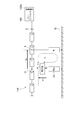
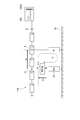
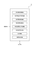
- FIG. 1 It is a schematic block diagram which shows the solar energy power generation system provided with the ground fault detection apparatus which concerns on 1st Embodiment. It is a figure for demonstrating the principle of a ground fault detection method. It is another figure for demonstrating the principle of a ground fault detection method. It is a functional block diagram which shows the calculation control part of the ground fault detection apparatus of FIG. It is a flowchart which shows operation
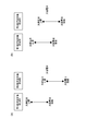
- (A) is a figure which shows another example of the electric potential state of a solar cell
- (b) is a figure which shows another example in the electric potential state of a solar cell.
- FIG. 1 is a schematic configuration diagram illustrating a solar power generation system including a ground fault detection device according to the first embodiment. As shown in FIG. 1, the ground fault detection device 1 detects a ground fault in the solar cell 110 in the solar power generation system 100. First, the solar power generation system 100 will be described.
- the solar power generation system 100 is a power generation system that generates power using solar energy, and includes a solar cell array 101 as a solar cell 110 and a power conditioner (load device) 102.
- the solar cell array 101 converts solar energy into electric energy and supplies it to the power conditioner 102 as a DC output.
- Each of the plurality of solar cell strings 103 is configured by connecting a plurality (here, 10) of solar cell modules 104 in series.
- the positive and negative electrodes of the plurality of solar cell strings 103 are aggregated and connected in parallel to form a positive and negative bus, and the positive and negative buses are connected to the power conditioner 102.
- the power conditioner 102 converts the DC output supplied from the solar cell array 101 into an AC output, and supplies the AC output to a subsequent power system (for example, a commercial power system).
- the power conditioner 102 is of a transformer insulation type, and has an insulation transformer 102a as an insulation part that insulates the solar cell 110 from the ground G that is the ground potential.
- the power conditioner 102 may be a transformerless (non-insulated) type, and in this case, another insulating unit different from the insulating transformer 102 a is installed in the photovoltaic power generation system 100.
- This power conditioner 102 is an operation voltage control function for controlling the operation voltage of the solar cell array 101 so that the maximum output of the solar cell array 101 is obtained, and the system is safely stopped when an abnormality in the power system is detected.
- System protection function a surge absorber 102b for releasing an overvoltage generated in the photovoltaic power generation system 100 to the ground G is provided as a system protection function.
- the surge absorber 102b is set with a positive electrode side set potential and a negative electrode side set potential.
- the surge absorber 102b When the positive electrode side of the solar cell 110 becomes equal to or higher than the positive electrode side set potential, the surge absorber 102b is connected to the ground G and releases the overvoltage to the ground G.
- the negative electrode side of the solar cell 110 becomes equal to or lower than the negative electrode side set potential, the solar cell 110 is connected to the ground G and releases the overvoltage to the ground G.
- FIGS. 2 and 3 are diagrams for explaining the principle of the ground fault detection method.
- the insulation resistance value R L and the potential of the ground fault location T according to the following principle.
- V L ground fault position, leakage voltage value
- the solar cell 110 is insulated from the ground G by the insulating transformer 102 a of the power conditioner 102.
- a predetermined location (first and second predetermined locations) O of the insulated solar cell 110 is grounded to the ground G via a voltage source (first and second DC power supply, DC voltage generator) 111.
- the first DC voltage value V 1 is applied to measure the first current value I 1 .
- measuring a second current value I 2 by applying a second DC voltage value V 2.
- the first and second DC voltage values V 1 and V 2 are two different applied voltages.
- the resistor 22 is provided on the ground G side of the voltage source 111.
- R d1 and R d2 it is assumed that the resistor 22 in FIG. 2 and the resistor 22 in FIG. 3 have different resistance values R d1 and R d2 .
- the first and second DC voltage values V 1 and V 2 are obtained when the point B is set between the resistor 22 and the voltage source 111 and the point A is set between the solar cell 110 and the voltage source 111. The potential of point A with respect to the point is used.
- the first and second DC voltage values V 1 and V 2 are the voltage source 111 when the voltage source 111 is provided on the ground G side of the resistor 22 (when the arrangement of the voltage source 111 and the resistor 22 is reversed). And the potential at point B with respect to the point between ground and ground G.
- the first and second current values I 1 and I 2 are currents that flow from the ground G toward the solar cell 110 and pass through the voltage source 111.
- the potential V L of the ground fault location T is the potential of the ground fault location T with respect to the predetermined location O which is a voltage application point.
- the ground fault detection device 1 of the present embodiment includes a measurement unit 2, a calculation control unit (control unit, computer) 3, and a storage unit 4.
- the measuring unit 2 performs measurement for detecting a ground fault with respect to the disconnected solar cell string 103.
- the measurement unit 2 includes a first measurement circuit 20A including a first grounding circuit 21A, a first resistor 22A, a first DC power supply 23A, and a first ammeter 24A, a second grounding circuit 21B, a second resistor 22B, and a second resistor.
- a second measurement system 20B including a DC power supply 23B and a second ammeter 24B.
- the first grounding circuit 21A has one side connected to the ground G.
- the other side of the first grounding electric circuit 21A can be connected to the electric circuit between the positive electrode side of the solar cell array 101 and the power conditioner 102.
- the other side of the first grounding electric circuit 21A is connected to the positive electrode bus of the solar cell array 101 via the first switch part 25A.
- the first switch section 25A is for switching electrical connection / disconnection of the first ground circuit 21A with respect to the solar cell array 101.
- a semiconductor switch such as a FET (Field Effect Transistor, Field Effect Transistor) or a mechanical switch such as a relay switch can be used.
- the first switch unit 25 ⁇ / b> A is connected to the calculation control unit 5 and switches on and off according to an instruction signal from the calculation control unit 5.
- the first resistor 22A is provided between the first switch unit 25A and the ground G on the first grounding electric circuit 21A.
- Resistance R d of the first resistor 22A is in terms of safety upon the ground fault occurs or exceeds a predetermined lower limit value, and is in terms of measuring the ease of measurement to be described later below a predetermined upper limit value (Same for the following resistors).
- the first DC power supply 23A is provided on the first ground circuit 21A between the first switch portion 25A and the first resistor 22A (on the solar cell array 101 side with respect to the first resistor 22A). That is, the first DC power supply 23A has one side as the negative electrode side connected to the first resistor 22A, and the other side as the positive electrode side is a first predetermined side on the positive electrode side of the solar cell array 101 via the first switch portion 25A. Connected to the point O1.
- the first DC power supply 23 ⁇ / b> A applies a positive DC voltage (DC voltage) to the positive electrode side of the solar cell array 101.
- the first DC power source 23A applies a first DC voltage of the DC voltage value V 1.
- the first DC voltage value V 1 is set to a predetermined lower limit value or more from the viewpoint of improving the sensitivity of ground fault detection, and is set to a predetermined upper limit value or less from the viewpoint of preventing damage to the solar cell circuit to be measured (the following Same for DC voltage value).
- the first DC power supply 23A is connected to the arithmetic and control unit 5, first by applying a DC voltage value V 1 in response to an instruction signal from the operation control unit 5, also, the DC voltage value V 1 to be applied Store in the storage unit 6.
- the first ammeter 24A is provided between the first resistor 22A and the ground G on the first grounding electric circuit 21A.
- the first ammeter 24A is the first current value as the leakage current value at the first ground path 21A flows through the first resistor 22A (first measurement) is measured I 1.
- the first ammeter 24 ⁇ / b> A is connected to the calculation control unit 5, performs measurement of the first DC voltage value V 1 in accordance with an instruction signal from the calculation control unit 3, and stores the measurement result in the storage unit 4.
- a DC zero-phase current detector using a Hall element is used as the first ammeter 24A.
- the second grounding circuit 21B has one side connected to the ground G.
- the other side of the second grounding electric circuit 21B can be connected to an electric circuit between the positive electrode side of the solar cell array 101 and the power conditioner 102.
- the other side of the second grounding electric circuit 21B is connected to the positive electrode bus of the solar cell array 101 via the second switch part 25B.
- the second switch unit 25B switches electrical connection / disconnection of the second grounding electric circuit 21B with respect to the solar cell array 101.
- a semiconductor switch such as an FET or a mechanical switch such as a relay switch can be used as in the first switch unit 25A.
- the second switch unit 25 ⁇ / b> B is connected to the calculation control unit 5 and switches on / off according to an instruction signal from the calculation control unit 5.
- the second resistor 22B is provided between the second switch unit 25B and the ground G on the second grounding electric circuit 21B.
- the resistance of the second resistor 22B are equal resistance R d and the first resistor 22A.
- the second DC power supply 23B is provided between the second switch unit 25B and the first resistor 22B (on the solar cell array 101 side with respect to the first resistor 22B) on the first ground circuit 21B.
- the second DC power supply 23B has one side as the negative electrode side connected to the second resistor 22B, and the other side as the positive electrode side connected to the second predetermined portion on the positive electrode side of the solar cell array 101 via the second switch portion 25B. Connected to location O2.
- the second DC power supply 23B applies a positive DC voltage (DC voltage) to the positive electrode side of the solar cell array 101.
- the second DC power source 23B applies a second DC voltage of the DC voltage value V 2.
- Second DC voltage V 2 is different from the voltage value from the first DC voltage value V 1.
- the second DC power supply 23B is connected to the arithmetic and control unit 3, second by applying a DC voltage value V 2 in response to an instruction signal from the operation control unit 3, also the DC voltage value V 2 to be applied Store in the storage unit 4.
- the second ammeter 24B is provided between the second resistor 22B and the ground G on the second ground circuit 21B.
- the second ammeter 24B is a second current value as the leakage current value in the second grounding path 21B flows through the second resistor 22B (second measured value) is measured I 2.
- the second ammeter 24 ⁇ / b> B is connected to the calculation control unit 5, performs the measurement of the second DC voltage value V 2 according to the instruction signal from the calculation control unit 3, and stores the measurement result in the storage unit 4.
- a DC zero-phase current detector using a Hall element or the like is used similarly to the first ammeter 24A.
- the second predetermined place O2 as the applied voltage place is located on the same connection, and the potentials are equal to each other at least when the rated output of the solar cell 110 is assumed.
- the design potentials of the first and second predetermined portions O1 and O2 are equal to each other.
- FIG. 4 is a functional block diagram showing an arithmetic control unit of the ground fault detection apparatus of FIG.
- the arithmetic control unit 3 is for controlling the ground fault detection device 1 as a whole (computer).
- the calculation control unit 3 executes a ground fault detection program to be described later, performs measurement and storage by the measurement unit 2, calculation based on the measurement result, detection of an insulation resistance value and a potential at the ground fault point T, and whether or not a ground fault exists. Perform the determination.
- the arithmetic control unit 3 is connected to the measurement unit 2 and the storage unit 4.
- the arithmetic control unit 3 may be configured by a CPU (Central Processing Unit) or an analog IC circuit or a PLD (Programmable Logic Device) circuit.
- the arithmetic control unit 3 controls the first switch unit 25A to control the connection of the first ground circuit 21A to the solar cell array 101, and the first DC power source 23A to control the solar cell array.
- a first DC voltage application function to apply a DC voltage of the DC voltage value V 1 to 101
- a first current measurement function for measuring a first current value I 1 controls the first ammeter 24A, the first measurement It has as a function.
- the arithmetic control unit 3 also controls the second switch unit 25B to control the connection of the second grounding electric circuit 21B to the solar cell array 101, and the second DC power source 23B to control the solar cell.
- a second DC voltage applying function for applying a DC voltage of the DC voltage value V 2 to the array 101
- a second current measurement function of measuring a second current value I 2 controls the second ammeter 24B
- the second Has a measurement function for applying a DC voltage of the DC voltage value V 2 to the array 101
- a second current measurement function of measuring a second current value I 2 controls the second ammeter 24B
- the second Has a measurement function the second has a measurement function.
- the calculation control unit 3 has a storage function of storing the measurement status, measurement results, and calculation results in the storage unit 4. Further, the calculation control unit 3 performs a calculation based on the measurement result stored in the storage unit 4 to detect the insulation resistance value R L and the potential V L of the ground fault location T and detect the presence or absence of the ground fault (determination). It has a ground fault detection function.
- the storage unit 4 is a recording medium for storing a ground fault detection program executed by the calculation control unit 3, a measurement result by the measurement unit 2, and a calculation result and a detection result by the calculation control unit 3. is there.
- the storage unit 4 a semiconductor memory, a magnetic storage device, or the like can be used.
- an external storage device for example, a hard disk
- the calculation control unit 3 may execute processing related to ground fault detection.
- the first and second switch portions 25A and 25B are turned off in the ground fault detection device 1, and the ground electric circuits 21A and 21B are not connected to the solar cell array 101. And when detecting the ground fault in the solar cell array 101, various functions are performed by the calculation control part 3, and the following operation
- the first switch unit 25A is turned on, the first grounding circuit 21A is connected to the positive electrode side of the solar cell array 101, the second switch unit 25B is kept off, and the second grounding circuit 21B is connected to the solar cell.
- the positive electrode side of the array 101 is disconnected (S1).
- the first DC power source 23A applying a first DC voltage value V 1 of the positive voltage to the positive electrode side of the solar cell array 101 (S2).
- the first current value I 1 flowing in the first ground path 21A was measured by a current meter 24A, the storage unit 6 (S3).
- the first switch unit 25A is turned off, the first grounding circuit 21A is disconnected from the positive electrode side of the solar cell array 101, the second switch unit 25B is turned on, and the second grounding circuit 21B is connected to the solar cell array. It connects with the positive electrode side of 101 (S4).
- the second DC power source 23B applying a second DC voltage value V 2 of the positive voltage to the positive electrode side of the solar cell array 101 (S5).
- the second current value I 2 flowing in the first ground path 21B is measured by a current meter 24B, the storage unit 6 (S6).
- the presence / absence of a ground fault is determined based on changes in the first and second current values I 1 and I 2 . That is, the insulation resistance value RL is calculated and detected from the first and second current values I 1 and I 2 according to the above equation (2) (S7).
- the first and second current value from the above equation (3) I 1, I 2 calculates the potential V L of the earth ⁇ plants T from then detected (S8).
- the calculated insulation resistance value RL is compared with the reference resistance value stored in advance in the storage unit 6 to determine the ground fault of the solar cell array 101 (S9). Specifically, when the insulation resistance value RL is smaller than the reference resistance value, it is determined that “ground fault exists”, while when the insulation resistance value RL is equal to or greater than the reference resistance value, it is determined that there is no ground fault. .
- the measurement of the first and second current values I 1 and I 2 and the detection of the ground fault are suppressed from being adversely affected by the dielectric loss. be able to. Furthermore, it is not necessary to use DPS for ground fault detection, and the measurement and processing of the first and second current values I 1 and I 2 can be performed easily and inexpensively.
- the present embodiment it is possible to accurately detect the ground fault at low cost. Moreover, when detecting a ground fault, a short circuit operation is not required, and safety can be improved. Furthermore, since the occurrence of an accident current is not a prerequisite for ground fault detection, as in the case of ground fault detection by the zero-phase current detection method, for example, the occurrence of the accident current can be suppressed.
- the first and second DC voltage values V 1 and V 2 are applied to the solar cell 110 to measure the first and second current values I 1 and I 2, that is, Two kinds of measured values are measured by applying two types of DC voltages to the solar cell 110. Therefore, as shown in the above formulas (2) and (3), the insulation resistance value R L and the potential V L of the ground fault location T are set as unknowns and calculated based on the first and second current values I 1 and I 2. Thus, it is possible not only to detect the insulation resistance value R L regardless of the potential V L of the ground fault location T, but also to reliably detect the potential V L. In addition, when two types of DC voltages can be applied to the solar cell 110 in this way, the ground potential of the solar cell 110 can be freely controlled, and the ground fault can be detected more reliably.
- the solar cell 110 can be prevented from being damaged by overcurrent, and the first and second measured values can be easily measured. Is possible.
- the first and second predetermined portions O1 and O2 to which the DC voltage is applied have the same potential when the rated output of the solar cell 110 is assumed. Therefore, the potentials at the first and second predetermined locations O1 and O2 are not taken into consideration (the potentials at the first and second predetermined locations O1 and O2 are not included as parameters in the equations (2) and (3)).
- the insulation resistance value R L and the potential V L of the ground fault location T can be calculated and detected.
- the first and second predetermined locations O1 and O2 in the solar cell 110 are located on the same connection, so that the output state of the solar cell 110 is not affected. since the first and second predetermined locations O1, O2 may be generally maintained at the same potential, regardless of the output state of the solar cell 110, to accurately detect the insulation resistance R L and voltage V L of the earth ⁇ plants T It becomes possible.
- the first and second current values I 1 and I 2 have different signs. If they have different signs, I 1 -I 2 is substantially an addition of absolute values, and therefore, due to a digit loss (a phenomenon in which significant figures decrease when numerical values having rounding errors are subtracted). A decrease in detection sensitivity (detection accuracy) can be avoided. In addition to a decrease in accuracy due to a digit loss due to computation, there is a problem that if the absolute value of the difference between I 1 and I 2 is small, the accuracy is likely to decrease due to the influence of noise.
- the entire solar cell 110 becomes higher ground potential when the first DC voltage V 1 is applied, the It is preferable that the entire solar cell 110 be equal to or lower than the ground potential when the two DC voltage values V 2 are applied. Therefore, it is preferable to satisfy the following expressions (4) and (5).
- V 1 V b + V s / 2
- V 2 V b ⁇ V s / 2 (4)
- V s (5)
- V b potential of predetermined locations O 1 and O 2 that are voltage application locations with respect to the midpoint of the solar cell 110
- V s extreme voltage value of the solar cell 110
- the solar power generation system 100 is often provided with a surge absorber 102b. That is, the solar cell 110 cathode and the solar cell 110 negative electrode, in many cases the absolute value of the ground potential is protected so as not to exceed greatly the interelectrode voltage value V s of the solar cell 110.
- the solar cell 110 cathode - earth G and between the solar cell 110 negative - between the ground G in
- the absolute value of the ground potential of the positive electrode of the solar cell 110 or the absolute value of the ground potential of the negative electrode of the solar cell 110 exceeds about twice the inter-electrode voltage V s of the solar cell 110 by the installation, the current flows through the surge absorber 102b. Is often taken so that the absolute value of the ground potential does not increase any further.
- the upper limit of the ground potential of the positive electrode of the solar cell 110 in which the surge absorber 102b does not operate is about 2 ⁇ V s and the lower limit is about ⁇ V s.
- the solar cell 110 varies within this range. It is necessary to let Accordingly, the difference
- the first and second DC voltage values V 1 and V 2 are reduced, and the difference between the first and second DC voltage values V 1 and V 2 is reduced, thereby avoiding the generation of ground potential.
- the difference between the first and second DC voltage values V 1 and V 2 is extremely small, the above-described decrease in detection sensitivity becomes a problem.
- the middle point of the solar cell 110 of the inter-electrode voltage value V s is 300 V, when applying a ⁇ 150 V as the first and second DC voltage value becomes the state shown in FIG. 6 (a), concerns the detection sensitivity decreases Absent.
- ⁇ 100 V is applied as the first and second DC voltage values
- V 1 ⁇ V 2 20 V, which is significantly lower than V s (300 V), and there is a concern that the detection sensitivity may decrease. .
- the first DC voltage value V 1 is applied so that the potential of the negative electrode of the solar cell 110 is equal to or higher than the ground potential.
- a second DC voltage value V 2 so as to be less ground potential, it is possible to further increase the detection sensitivity.
- the power conditioner 102 is a transformer-less (non-insulated) type
- the insulation process the disconnection between the solar cell and the power conditioner 102, the disconnection between the power conditioner 102 and the power system, and the stop of the power conditioner 102 are performed.
- the insulation process when the disconnection between the solar cell 110 and the power conditioner 102 is performed, there is no possibility that the operation of the surge absorber 102b hinders the detection of the ground fault.
- the surge absorber 102b may be operated by applying a DC voltage as described later, and accurate measurement may not be performed.
- the solar cell 110 is insulated, so that special insulation treatment is not necessary.
- the surge absorber 102b provided in the power conditioner 102 operates as described below and accurate measurement cannot be performed. That is, when the surge absorber 102b is provided in the power conditioner 102 and the ground fault detection is attempted with the solar cell 110 and the power conditioner 102 connected, the surge absorber 102b is activated when a DC voltage is applied, and the voltage is grounded. There is a possibility that accurate measurement cannot be performed.
- V 1 (V Lp + V Ln ) / 2 (7)
- V 1 V c + V b + V S / 2 (8)
- V 2 V c + V b ⁇ V S / 2 (9)
- surge absorber 102b instead of or in addition to the surge absorber 102b, another surge absorber may be provided in, for example, a connection box (not shown).
- a connection box not shown.
- the detection sensitivity is improved by setting the first and second DC voltage values V 1 and V 2 to be applied, and the load on the solar cell 110 is suppressed as much as possible. It can also be used widely for various purposes.
- FIG. 8 is a schematic configuration diagram illustrating a solar power generation system including the ground fault detection device according to the second embodiment. As shown in FIG. 8, this embodiment is different from the first embodiment in that a measurement unit 202 is provided instead of the measurement unit 2 (see FIG. 1).
- the other side of the first ground path 21A is connected to a first predetermined position O1 which is the midpoint of the solar cell string 103 1.
- one side is of a negative electrode side of the first DC power source 23A, and is connected to a first predetermined position O1 which is the midpoint of the solar cell string 103 1 through the first switch unit 25A.
- the other side as the positive electrode side of the first DC power supply 23A is connected to the first resistor 22A.
- the first ground circuit 21A has a first voltmeter 26A for measuring a first voltage value (first measurement value) generated by the first resistor 22A.
- the first voltmeter 26A is connected between the first DC power supply 23A and the first resistor 22A, and between the first resistor 22A and the ground G.
- the first voltmeter 21 ⁇ / b> A is connected to the calculation control unit 3, and executes the measurement of the first voltage value according to the instruction signal from the calculation control unit 3.
- one side is of a positive electrode side of the second DC power source 23B, and is connected to a second predetermined position O2 is the midpoint of the solar cell string 103 2 via a second switch 25B.
- the other side as the negative electrode side of the second DC power supply 23B is connected to the second resistor 22B.
- the second ground circuit 21B has a second voltmeter 26B for measuring a second voltage value (second measured value) generated by the second resistor 22B.
- the second voltmeter 26B is connected between the second DC power supply 23B and the second resistor 22B and between the second resistor 22B and the ground G.
- the second voltmeter 21 ⁇ / b> B is connected to the calculation control unit 3 and executes measurement of the second voltage value in response to an instruction signal from the calculation control unit 3.
- the above-described effect of detecting a ground fault with high accuracy at low cost is achieved.
- the first and second DC power supplies 23A and 23B apply a low DC voltage, “the lowest voltage of the solar cell 110> the ground potential” and “the highest potential of the solar cell 110 ⁇ the ground potential”.
- the state of “potential” can be easily generated.
- FIG. 9 is a schematic configuration diagram illustrating a solar power generation system including the ground fault detection device according to the third embodiment. As shown in FIG. 9, the present embodiment is different from the second embodiment in that a plurality of solar cell strings 103 are electrically connected to each other at the midpoint, and the measuring unit 202 (see FIG. 8). It is the point provided with the measurement part 302 instead of.
- the measurement unit 302 has the other side of the first and second grounding electric circuits 21 ⁇ / b> A and 21 ⁇ / b> B connected to a predetermined location O that is a midpoint connected to each other in the plurality of solar cell strings 103. Specifically, one side as the negative electrode side of the first DC power supply 23A and one side as the positive electrode side of the second DC power supply 23B are connected to the predetermined location O via the third switch portion 25C.
- the third switch unit 25C is a c-contact switch, and alternatively connects the predetermined portion O to either the first DC power source 23A or the second DC power source 23B.
- the above-described effect of detecting a ground fault with high accuracy at low cost is achieved.
- the ground fault of the solar cell 110 can be detected even if some of the plurality of solar cell strings 103 are disconnected. Furthermore, when some of the solar cell strings 103 are disconnected from the solar cell array 101, there is a risk that voltage application to the midpoint may be impossible in the first embodiment, but in the present embodiment, There is no fear, and it becomes possible to reliably apply a voltage to the middle point.
- FIG. 10 is a schematic configuration diagram illustrating a solar power generation system including the ground fault detection device according to the fourth embodiment. As shown in FIG. 10, this embodiment is different from the first embodiment in that a measurement unit 402 is provided instead of the measurement unit 2 (see FIG. 1).
- the measuring unit 402 is connected to a predetermined location O obtained by dividing the positive electrode and the negative electrode of the solar cell array 101 by two resistors 28A and 28B.
- the resistors 28A and 28B have the same resistance value Rdiv .
- one side as the negative electrode side of the first DC power source 23A and one side as the positive electrode side of the second DC power source 23B are connected to a predetermined location O via the third switch unit 25C.
- the other side of the negative electrode side of the other side and the second DC power source 23B as the positive electrode side of the first DC power supply 23A is connected to each other, the connection point K through the resistor 29 of resistance R d Daichi G is connected.
- the third switch unit 25C is a c-contact switch, and alternatively connects the predetermined portion O to either the first DC power source 23A or the second DC power source 23B.
- the voltmeter 26 is connected between the connection point K and the resistor 29 and between the resistor 29 and the ground G.
- the voltmeter 26 is connected to the calculation control unit 3, and in response to an instruction signal from the calculation control unit 3, a first voltage value (first measured value) V d1 or a second voltage value ( Second measurement value) V d2 is measured.
- the calculation control unit 3 calculates the first and second voltage flow values V d1 and V d2 measured by the measurement unit 402 based on the following equations (10) to (13), The insulation resistance value R L and the potential V L of the ground fault location T are obtained.
- R L (V 2 ⁇ V 1 ) / (I 2 ⁇ I 1 ) ⁇ R d ⁇ R div / 2 (10)
- V L (I 1 ⁇ V 2 ⁇ I 2 ⁇ V 1 ) / (I 2 ⁇ I 1 ) (11)
- I 1 V d1 / R d (12)
- I 2 V d2 / R d (13)
- the above-described effect of detecting a ground fault with high accuracy at low cost is achieved.
- the ground fault of the solar cell 110 can be detected even if some of the plurality of solar cell strings 103 are disconnected.
- FIGS. 11A to 11D are diagrams showing one state of the measurement unit according to the modification.
- the measurement units 202, 302, and 402 according to the modification include a DC power source (first and second DC power source, DC voltage generation unit) 23 ⁇ / b> C that applies a DC voltage V, a voltmeter 26, Only one resistor 29 is provided, the measuring unit 202 includes a switch unit 25D, and the measuring units 302 and 402 include a switch unit 25E.
- the switch unit 25D connects one side as the negative electrode side of the DC power source 23C to the resistor 29 by switching the switch element to the state illustrated in FIG.
- the other side as the positive electrode side of the DC power supply 23C is connected to the predetermined location O2.
- a positive DC voltage V is applied to the predetermined location O2.
- the switch unit 25E switches the switch element to the state shown in the figure, thereby connecting one side as the negative side of the DC power supply 23C to the resistor 29.
- the other side as the positive electrode side of the DC power supply 23C is connected to the predetermined location O.
- a positive DC voltage V is applied to the predetermined location O.
- the switch unit 25D connects one side as the negative electrode side of the DC power supply 23C to the predetermined location O1 by switching the switch element to the illustrated state.
- the other side as the positive electrode side of the DC power supply 23C is connected to the resistor 29.
- a negative DC voltage V is applied to the predetermined location O1.
- the switch unit 25E switches the switch element to the illustrated state, thereby setting one side as the negative electrode side of the DC power supply 23C to a predetermined location.
- the other side as the positive electrode side of the DC power supply 23C is connected to the resistor 29 while being connected to O.
- a negative DC voltage V is applied to the predetermined location O.
- the first and second voltage flow values V d1 and V d2 can be measured by changing the connection of one DC power supply 23C.
- the said embodiment is provided with the 1st DC power supply 23A provided on 21 A of 1st earthing circuits, and the 2nd DC power supply 23B provided on the 2nd earthing circuit 21B, either one of these is provided. You may have only. Specifically, for example, as illustrated in FIG. 12, the second DC power supply 23B (see FIG. 1) is not provided on the second grounding circuit 21B, and the second grounding circuit 21B is connected to the solar cell array 101. A DC voltage may not be applied when connected (in other words, a DC voltage value of 0 V is applied).
- the first and second grounding electric circuits 21A and 21B can be connected to the positive electrode side of the solar cell array 101.
- the first and second grounding electric circuits 21A and 21B can be connected to the negative electrode side of the solar cell array 101. May be connectable.
- the first and second DC power sources 23A and 23B are connected to the first and second DC power sources 23A and 23B, respectively, so as to apply a negative DC voltage in order to suitably suppress the generation of a ground potential in the solar cell array 101. It is preferable to provide on the grounding electric circuits 21A and 21B.
- a second current value I 2 measured Te after (the S4 ⁇ S6) is obtained by measuring a second current value I 2 to connect the second ground path 21B to the solar cell array 101, the sun of the first ground path 21A
- the first current value I 1 may be measured by connecting to the battery array 101.
- the first and second current values I 1 and I 2 are directly measured as “measured values related to the current value” by the ammeters 24A and 24B.
- the present invention is not limited to this. May be used to measure the voltage values of the resistors 22A and 22B. In this case, the voltage values correspond to “measured values relating to current values”.
- the embodiment may further include a grounding circuit similar to the first and second grounding circuits 21A and 21B. That is, three or more different types of DC voltages are sequentially applied to the solar cell array 101. A ground fault may be detected by detecting a change in each leakage current value when the DC voltage is applied.
- the predetermined locations O1 and O2 are not limited to being on the same connection or the same potential, and are any location that is electrically connected to the solar cell 110 (solar cell array 101). Good.
- the predetermined locations O1 and O2 may be the same predetermined location O on the same connection. That is, the predetermined location O can be connected to the first DC power supply 23A and the second DC power supply 23B via a c-contact switch, and the predetermined location O is either the first DC power supply 23A or the second DC power supply 23b. Alternatively, connection may be made. In this case, the number of switches can be reduced and the circuit configuration can be simplified, and a malfunction that both the first DC power supply 23A and the second DC power supply 23B are connected to the solar cell 110 can be prevented.
- the power conditioner 102 is provided as a load device.
- the load device only needs to consume or convert electric power, and may be a DC load such as a converter or a storage battery.
- the above “equal” includes substantially equal, and allows variations and errors in manufacturing, design, and measurement.
- the first DC power source 23A and the second DC power source 23B may be regarded as constituting a DC voltage generating unit, or the voltage source 111 may be regarded as constituting first and second DC power sources. It may be considered that the power source 23C constitutes the first and second DC power sources.
- the first grounding circuit has a first resistance connected in series
- the second grounding circuit has a second resistance
- the first measurement process is a current flowing through the first resistance.
- the measurement value is measured by the measurement unit as the first measurement value
- the measurement value regarding the current flowing through the second resistor is measured by the measurement unit as the second measurement value.
- the solar cell can be prevented from being damaged by an overcurrent by interposing the first and second resistors.
- the first predetermined portion and the second predetermined portion of the solar cell have the same potential at least when the rated output of the solar cell is assumed. In this case, it is possible to detect the insulation resistance value and the potential at the ground fault location without considering the potential at the first and second predetermined locations.
- the first predetermined portion and the second predetermined portion of the solar cell are located on the same connection. Since the same potential is maintained on the same connection regardless of the output status of the solar cell, by providing the first predetermined location and the second predetermined location on the same connection, regardless of the output status of the solar cell In addition, it is possible to accurately detect the insulation resistance value and potential at the ground fault location.
- the solar cell further includes a second DC power source provided in series with the second resistor on the second ground circuit, and applying a second DC voltage value to the solar cell, and the second measurement process is performed by insulating the solar cell from the ground.
- the second grounding circuit is connected to the second predetermined location of the battery, the second DC voltage value is applied to the solar cell by the second DC power source, and the second measurement value is measured by the measurement unit in this state.
- the absolute value of the difference between the first and second DC voltage values is as follows when the first DC voltage value is V 1 , the second DC voltage value is V 2 , and the voltage across the solar cell is V s: It is preferable to satisfy the formula (1). 1/2 ⁇
- digits are dropped in the calculation process (the number of significant digits is reduced). Phenomenon) may occur.
- the first DC voltage value is applied so that the potential of the negative electrode of the solar cell is equal to or higher than the ground potential
- the potential of the positive electrode of the solar cell is equal to or lower than the ground potential. It is preferable to apply a second direct current voltage value to the power source.
- the current flowing through the ground fault location in the first measurement process and the current flowing through the ground fault location in the second measurement process are always different from each other regardless of the ground fault location.
- production can be suppressed further and it becomes possible to detect a ground fault still more sensitively.
- the solar power generation system also includes a surge absorber for escaping overvoltage generated in the solar power generation system to the ground.
- the potential of the positive electrode of the solar cell is equal to or lower than the set potential on the positive electrode side of the surge absorber. It is preferable that the first DC voltage value is applied so that the second DC voltage value is applied so that the potential of the negative electrode of the solar cell is equal to or higher than the positive electrode side set potential of the surge absorber. .
- the present invention uses a ground fault detection device, a ground fault detection method, a solar power generation system, and a ground fault detection program, and can detect a ground fault with low cost and high accuracy.
- first DC power supply Second DC power supply, DC voltage generator
- I 1 ... first current value first measured value
- I 2 ... second current value second measured value
- G ... ground
- O ... measured location first 1 measuring point, the second measurement point
- O 1 ... first predetermined position second ... second predetermined position
- V 1 ... first DC voltage value V 2 ... second DC voltage value
- V d1 ... first voltage value (first measurement)
- V d2 ... second voltage value (second measurement value).
Landscapes
- Engineering & Computer Science (AREA)
- Power Engineering (AREA)
- Physics & Mathematics (AREA)
- General Physics & Mathematics (AREA)
- Testing Of Short-Circuits, Discontinuities, Leakage, Or Incorrect Line Connections (AREA)
- Emergency Protection Circuit Devices (AREA)
- Photovoltaic Devices (AREA)
Abstract
大地Gに対し絶縁化された太陽電池110の第1所定箇所O1を第1接地電路21Aにより大地Gに接地し、当該第1測定箇所O1に第1直流電源23Aにより第1直流電圧値V1を印加し、この状態で第1接地電路21Aに流れる第1電流値I1を測定する。また、大地Gに対し絶縁化された太陽電池110の第2所定箇所O2を第2接地電路21Bにより大地Gに接地し、当該第2所定箇所O2に第2直流電源23Bにより第1直流電圧値V1とは異なる第2直流電圧値V2を印加し、この状態で第2接地電路21Bに流れる第2電流値I2を測定する。そして、測定した第1及び第2電流値I1,I2に基づいて地絡を検出する。
Description
本発明は、地絡検出装置、地絡検出方法、太陽光発電システム、及び地絡検出プログラムに関する。
従来、一般的な太陽光発電システムとして、太陽光が利用して発電を行う太陽電池と、この太陽電池で発電された電力を消費又は変換するパワーコンディショナ等の負荷装置と、を備えたものが知られている。このような太陽光発電システムにおいて太陽電池内に絶縁不良があると、例えば人や物が絶縁不良箇所に触れたときや、絶縁不良箇所と金属架台等とが接触したとき、電気回路が外部と意図しない形で接触する地絡が生じる場合がある。
そこで、この地絡を検出するものとして、例えば特許文献1に地絡検出装置が開示されている。特許文献1に開示された地絡検出装置では、接地された太陽電池の電路から大地に流れる漏れ電流値が測定され、この漏れ電流値が予め設定された電流設定値を超えたとき、太陽電池の地絡が検出される。
ところで、近年、上述したような地絡検出装置として、例えば交流電源により交流電圧を太陽電池に印加し、交流電圧を介して太陽電池と大地との間に流れる電流値及びその波形データを測定し、これら電流値及び波形データに基づき地絡を検出するもの(いわゆる、ACバイアス法による地絡検出装置)が開発されている。しかし、この地絡検出装置では、誘電損失をキャンセルすることが困難である。さらには、波形データの測定が必要なことから高価なDPS(Digital Signal Processing)が要されるため、高コスト化するという問題がある。
本発明は、このような事情に鑑みてなされたものであり、低コストで精度よく地絡を検出できる地絡検出装置、地絡検出方法、太陽光発電システム及び地絡検出プログラムを提供することを課題とする。
上記課題を解決するため、本発明の一側面に係る地絡検出装置は、太陽光を利用して発電を行う太陽電池と、太陽電池で発電された電力を消費又は変換する負荷装置と、を具備する太陽光発電システムにおいて、太陽電池内の地絡を検出する地絡検出装置であって、一方側が大地に接続されていると共に、他方側が太陽電池の第1所定箇所に接続可能な第1接地電路と、一方側が大地に接続されていると共に、他方側が太陽電池の第2所定箇所に接続可能な第2接地電路と、第1接地電路上に設けられ、太陽電池に第1直流電圧値を印加する第1直流電源と、第1接地電路に流れる電流に関する第1測定値、及び第2接地電路に流れる電流に関する第2測定値を測定する測定部と、測定部の動作の制御と、測定部により測定された第1及び第2測定値に基づく地絡検出と、を実施する制御部と、を備え、制御部は、大地に対し絶縁化された太陽電池に第1接地電路を接続させ、第1直流電源により第1直流電圧値を太陽電池に印加させ、この状態で測定部により第1測定値を測定させる第1測定処理と、大地に対し絶縁化された太陽電池に第2接地電路を接続させ、この状態で測定部により第2測定値を測定させる第2測定処理と、測定させた第1及び第2測定値に基づいて地絡の検出を行う地絡検出処理と、を実行すること、と特徴とする。
また、本発明の一側面に係る地絡検出装置は、太陽光を利用して発電を行う太陽電池と、太陽電池で発電された電力を消費又は変換する負荷装置と、を具備する太陽光発電システムにおいて、太陽電池内の地絡を検出する地絡検出装置であって、一方側が大地に接続されていると共に他方側が太陽電池の所定箇所に接続可能とされ、少なくとも第1直流電圧値と第2直流電圧値を生成し出力する直流電圧生成部と、所定箇所から大地に流れる電流に関する第1及び第2測定値を測定する測定部と、測定部と直流電圧生成部の動作の制御、及び測定部により測定された測定結果に基づく地絡検出を実行する制御部と、を備え、制御部は、大地に対し絶縁化された太陽電池に直流電圧生成部を接続させ、直流電圧生成部により第1直流電圧値を所定箇所に印加させ、この状態で測定部により第1測定値を測定させる第1測定処理と、大地に対し絶縁化された太陽電池に直流電圧生成部を接続させ、直流電圧生成部により第2直流電圧値を所定箇所に印加させ、この状態で測定部により第2測定値を測定させる第2測定処理と、測定させた第1及び第2測定値に基づいて地絡の検出を行う地絡検出処理と、を実行することを特徴とする。
上記一側面の地絡検出装置では、直流電圧を太陽電池に印加するため、誘電損失による悪影響が地絡検出に及ぶのを抑制することができる。また、地絡検出にDPSを用いる必要がなく、第1及び第2測定値の測定及び処理を容易且つ安価に行うことが可能となる。さらには、地絡検出に際して、2つの測定値、つまり第1及び第2測定値を測定しているため、地絡箇所の絶縁抵抗値及び電位を未知数とし第1及び第2測定値に基づき演算することで、これら絶縁抵抗値及び電位をも確実に検出することができる。従って、上記一側面によれば、低コストで確実に地絡を検出することが可能となる。
なお、「太陽電池」は、1つの太陽電池セルや1つの太陽電池モジュールであってもよいし、複数の太陽電池モジュールを直列に接続した太陽電池ストリングであってもよいし、複数の太陽電池ストリングを並列に接続した太陽電池アレイであってもよい。或いは、複数の太陽電池モジュールの直列又は並列の接続状態を随時切り替えるシステムであってもよい(以下、同じ)。
また、本発明の第1の他の側面に係る地絡検出方法は、太陽光を利用して発電を行う太陽電池と、太陽電池で発電された電力を消費又は変換する負荷装置と、を具備する太陽光発電システムにおいて、太陽電池内の地絡を検出する地絡検出方法であって、大地に対し絶縁化された太陽電池の第1所定箇所と大地との間に第1直流電圧値を印加し、この状態で第1所定箇所と大地との間を流れる電流に関する第1測定値を測定する第1測定ステップと、大地に対し絶縁化された太陽電池の第2所定箇所と大地との間に第1直流電圧値とは異なる第2直流電圧値を印加し、この状態で第2所定箇所と大地との間を流れる電流に関する第2測定値を測定する第2測定ステップと、測定した第1及び第2測定値に基づいて地絡を検出する地絡検出ステップと、を備えたことを特徴とする。
また、本発明の第2の他の側面に係る太陽光発電システムは、太陽光を利用して発電を行う太陽電池と、太陽電池で発電された電力を消費又は変換する負荷装置と、上記地絡検出装置と、を具備すること、を特徴とする。
また、本発明の第3の他の側面に係る地絡検出プログラムは、太陽光を利用して発電を行う太陽電池と、太陽電池で発電された電力を消費又は変換する負荷装置と、を具備する太陽光発電システムにおいて、太陽電池内の地絡を検出するための地絡検出プログラムであって、大地に対し絶縁化された太陽電池の第1所定箇所と大地との間に第1直流電圧値を印加させ、この状態で第1所定箇所と大地との間を流れる電流に関する第1測定値を測定させる第1測定機能と、大地に対し絶縁化された太陽電池の第2所定箇所と大地との間に第1直流電圧値とは異なる第2直流電圧値を印加させ、この状態で第2所定箇所と大地との間を流れる電流に関する第2測定値を測定させる第2測定機能と、をコンピュータに実行させること、を特徴とする。
これらの他の側面に係る地絡検出方法、太陽光発電システム、及び地絡検出プログラムにおいても、上記作用効果、すなわち、低コストで精度よく地絡を検出できるという作用効果が奏される。
本発明によれば、低コストで精度よく地絡を検出することが可能となる。
以下、図面を参照しながら、本発明の好適な実施形態について詳細に説明する。なお、以下の説明では、同一又は相当要素には同一符号を付し、重複する説明は省略する。
[第1実施形態]
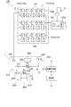
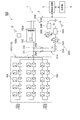
図1は、第1実施形態に係る地絡検出装置を備えた太陽光発電システムを示す概略構成図である。図1に示すように、地絡検出装置1は、太陽光発電システム100において太陽電池110内の地絡を検出するものである。そこで、まず、この太陽光発電システム100について説明する。
図1は、第1実施形態に係る地絡検出装置を備えた太陽光発電システムを示す概略構成図である。図1に示すように、地絡検出装置1は、太陽光発電システム100において太陽電池110内の地絡を検出するものである。そこで、まず、この太陽光発電システム100について説明する。
太陽光発電システム100は、太陽光エネルギを利用して発電を行う発電システムであり、太陽電池110としての太陽電池アレイ101と、パワーコンディショナ(負荷装置)102と、を備えている。太陽電池アレイ101は、太陽光エネルギを電気エネルギへ変換し、直流出力としてパワーコンディショナ102へ供給する。太陽電池アレイ101は、複数の太陽電池ストリング103が並列接続されて構成されている。つまり、太陽電池アレイ101においては、第1~第n太陽電池ストリング1031~103nが並列接続されている(nは2以上の整数:ここではn=3)。
複数の太陽電池ストリング103のぞれぞれは、複数(ここでは、10個)の太陽電池モジュール104が直列接続されて構成されている。これら複数の太陽電池ストリング103の正極及び負極は、集約され並列接続されて正極母線及び負極母線が構成され、当該正極母線及び負極母線は、パワーコンディショナ102に接続されている。
パワーコンディショナ102は、太陽電池アレイ101から供給された直流出力を交流出力に変換し、この交流出力を後段の電力系統(例えば商用電力系統)へ供給する。パワーコンディショナ102は、トランス絶縁型とされており、太陽電池110を接地電位である大地Gと切り離して絶縁化させる絶縁化部としての絶縁トランス102aを有している。なお、パワーコンディショナ102は、トランスレス(非絶縁)型とされていてもよく、この場合、絶縁トランス102aとは別の他の絶縁化部が太陽光発電システム100に設置される。
このパワーコンディショナ102は、太陽電池アレイ101の最大出力が得られるよう太陽電池アレイ101の動作電圧を制御する動作電圧制御機能と、電力系統の異常が検知された場合に安全にシステム停止する等の系統保護機能と、を有している。ここでは、太陽光発電システム100に生じる過電圧を大地Gへ逃がすためのサージアブソーバ102bを、系統保護機能として有している。
サージアブソーバ102bは、正極側設定電位及び負極側設定電位が設定されており、太陽電池110の正極側が正極側設定電位以上となったとき、大地Gと接続してその過電圧を大地Gへ逃がすと共に、太陽電池110の負極側が負極側設定電位以下となったとき、大地Gと接続してその過電圧を大地Gへ逃がす。
図2,3は、地絡検出方法の原理を説明するための図である。図2,3に示すように、本実施形態では、例えば太陽電池110内の地絡箇所Tで地絡が発生している場合、以下の原理により地絡箇所Tの絶縁抵抗値RL及び電位VL(地絡位置,漏れ電圧値)をも検出する。
すなわち、まず、例えばパワーコンディショナ102の絶縁トランス102aによって太陽電池110を大地Gに対し絶縁化する。絶縁化された太陽電池110の所定箇所(第1及び第2所定箇所)Oを、電圧源(第1及び第2直流電源,直流電圧生成部)111を介して大地Gに接地する。そして、第1直流電圧値V1を印加して第1電流値I1を測定する。また、第2直流電圧値V2を印加して第2電流値I2を測定する。
第1及び第2直流電圧値V1,V2は、互いに異なる2種の印加電圧である。抵抗22は、電圧源111の大地G側に設けられている。ここでは、一般化のため、図2中の抵抗22と図3中の抵抗22とは、互いに異なる抵抗値Rd1,Rd2を有するものとする。第1及び第2直流電圧値V1,V2は、抵抗22と電圧源111との間にB点を設定し、太陽電池110と電圧源111との聞にA点を設定したとき、B点に対するA点の電位とされている。なお、第1及び第2直流電圧値V1,V2は、電圧源111が抵抗22の大地G側に設けられた場合(電圧源111及び抵抗22の配置が逆の場合)、電圧源111と大地Gとの間の点に対するB点の電位とされる。
第1及び第2電流値I1,I2は、大地Gから太陽電池110に向って流れ電圧源111を通過する電流である。地絡箇所Tの電位VLは、電圧印可点である所定箇所Oに対する地絡箇所Tの電位である。
ここで、キルヒホッフの法則より、下式(2),(3)が成立する。よって、測定した第1及び第2電流値I1,I2を下式(2),(3)に代入することで、地絡箇所Tの絶縁抵抗値RL及び電位VLを求められることとなる。
RL=(V1-V2)/(I1-I2)-(Rd2×I2-Rd1×I1)/(I1-I2)…(2)
VL=(V1・I2-V2・I1+I1・I2×(Rd2―Rd1))/(I1-I2)…(3)
RL=(V1-V2)/(I1-I2)-(Rd2×I2-Rd1×I1)/(I1-I2)…(2)
VL=(V1・I2-V2・I1+I1・I2×(Rd2―Rd1))/(I1-I2)…(3)
なお、Rd1=Rd2=Rdの場合、上式(2)は下式(2)’に簡略化でき、上式(3)は下式(3)’に簡略化できる。
RL=(V1-V2)/(I1-I2)-Rd …(2)’
VL=(V1・I2-V2・I1)/(I1-I2) …(3)’
RL=(V1-V2)/(I1-I2)-Rd …(2)’
VL=(V1・I2-V2・I1)/(I1-I2) …(3)’
図1に戻り、本実施形態の地絡検出装置1は、測定部2と、演算制御部(制御部,コンピュータ)3と、記憶部4と、を備えている。測定部2は、解列された太陽電池ストリング103について地絡検出のための測定を行うものである。この測定部2は、第1接地電路21A、第1抵抗22A、第1直流電源23A及び第1電流計24Aを含む第1測定系20Aと、第2接地電路21B、第2抵抗22B、第2直流電源23B及び第2電流計24Bを含む第2測定系20Bと、を有している。
第1接地電路21Aは、その一方側が大地Gに接続されている。また第1接地電路21Aは、その他方側が太陽電池アレイ101の正極側とパワーコンディショナ102との間の電路に接続可能とされている。具体的には、第1接地電路21Aの他方側は、第1スイッチ部25Aを介して、太陽電池アレイ101の正極母線に接続されている。
第1スイッチ部25Aは、太陽電池アレイ101に対する第1接地電路21Aの電気的な接続/非接続を切り替えるものである。第1スイッチ部25Aとしては、FET(電界効果トランジスタ,Field Effect Transistor)等の半導体スイッチや、リレースイッチ等の機械式スイッチを用いることができる。この第1スイッチ部25Aは、演算制御部5に接続されており、演算制御部5からの指示信号に応じてオンオフを切り替える。
第1抵抗22Aは、第1接地電路21A上において第1スイッチ部25Aと大地Gとの間に設けられている。この第1抵抗22Aの抵抗値Rdは、地絡発生時の安全性の観点から所定下限値以上とされ、且つ、後述する測定値の測定容易性の観点から所定上限値以下とされている(以下の抵抗において同様)。
第1直流電源23Aは、第1接地電路21A上において第1スイッチ部25Aと第1抵抗22Aとの間(第1抵抗22Aよりも太陽電池アレイ101側)に設けられている。つまり、第1直流電源23Aは、その負極側としての一方側が第1抵抗22Aに接続され、その正極側としての他方側が第1スイッチ部25Aを介して太陽電池アレイ101の正極側の第1所定箇所O1に接続されている。この第1直流電源23Aは、太陽電池アレイ101の正極側に対し正電圧の直流電圧(DC電圧)を印加する。ここでは、第1直流電源23Aは、第1直流電圧値V1の直流電圧を印加する。
第1直流電圧値V1は、地絡検出の感度向上の観点から所定下限値以上とされ、且つ、測定対象の太陽電池回路を破損防止する観点から所定上限値以下とされている(以下の直流電圧値において同様)。この第1直流電源23Aは、演算制御部5に接続されており、演算制御部5からの指示信号に応じて第1直流電圧値V1を印加し、また、印加する直流電圧値V1を記憶部6に記憶する。
第1電流計24Aは、第1接地電路21A上において第1抵抗22Aと大地Gとの間に設けられている。この第1電流計24Aは、第1接地電路21Aにて第1抵抗22Aを介して流れる漏れ電流値としての第1電流値(第1測定値)I1を測定する。また、第1電流計24Aは、演算制御部5に接続されており、演算制御部3からの指示信号に応じて第1直流電圧値V1の測定を実行し、その測定結果を記憶部4に記憶する。第1電流計24Aとしては、例えばホール素子を利用した直流零相電流検出器等が用いられる。
他方、第2接地電路21Bは、その一方側が大地Gに接続されている。また第2接地電路21Bは、その他方側が太陽電池アレイ101の正極側とパワーコンディショナ102との間の電路に接続可能とされている。具体的には、第2接地電路21Bの他方側は、第2スイッチ部25Bを介して、太陽電池アレイ101の正極母線に接続されている。
第2スイッチ部25Bは、太陽電池アレイ101に対する第2接地電路21Bの電気的な接続/非接続を切り替えるものである。第2スイッチ部25Bとしては、上記第1スイッチ部25Aと同様に、FET等の半導体スイッチや、リレースイッチ等の機械式スイッチを用いることができる。この第2スイッチ部25Bは、演算制御部5に接続されており、演算制御部5からの指示信号に応じてオンオフを切り替える。
第2抵抗22Bは、第2接地電路21B上において第2スイッチ部25Bと大地Gとの間に設けられている。この第2抵抗22Bの抵抗値は、上記第1抵抗22Aと等しい抵抗値Rdとされている。
第2直流電源23Bは、第1接地電路21B上において第2スイッチ部25Bと第1抵抗22Bとの間(第1抵抗22Bよりも太陽電池アレイ101側)に設けられている。つまり、第2直流電源23Bは、その負極側としての一方側が第2抵抗22Bに接続され、その正極側としての他方側が第2スイッチ部25Bを介して太陽電池アレイ101の正極側の第2所定箇所O2に接続されている。この第2直流電源23Bは、太陽電池アレイ101の正極側に対し正電圧の直流電圧(DC電圧)を印加する。ここでは、第2直流電源23Bは、第2直流電圧値V2の直流電圧を印加する。
第2直流電圧値V2は、上記第1直流電圧値V1とは異なる電圧値とされている。この第2直流電源23Bは、演算制御部3に接続されており、演算制御部3からの指示信号に応じて第2直流電圧値V2を印加し、また、印加する直流電圧値V2を記憶部4に記憶する。
第2電流計24Bは、第2接地電路21B上において第2抵抗22Bと大地Gとの間に設けられている。この第2電流計24Bは、第2接地電路21Bにて第2抵抗22Bを介して流れる漏れ電流値としての第2電流値(第2測定値)I2を測定する。また、第2電流計24Bは、演算制御部5に接続されており、演算制御部3からの指示信号に応じて第2直流電圧値V2の測定を実行し、その測定結果を記憶部4に記憶する。第2電流計24Bとしては、上記第1電流計24Aと同様に、例えばホール素子を利用した直流零相電流検出器等が用いられる。
なお、太陽電池110において、第1直流電源23Aから第1直流電圧値V1が印加される電圧印可箇所としての第1所定箇所O1と、第2直流電源23Bから第2直流電圧値V2が印加される電圧印可箇所としての第2所定箇所O2とは、同一の結線上位置しており、少なくとも太陽電池110の定格出力想定時において電位が互いに等しくなっている。換言すると、第1及び第2所定箇所O1,O2は、設計上の電位が互いに等しくされている。
図4は、図1の地絡検出装置の演算制御部を示す機能ブロック図である。図1,4に示すように、演算制御部3は、地絡検出装置1全体を制御するためのもの(コンピュータ)である。ここでの演算制御部3は、後述の地絡検出プログラムを実行し、測定部2による測定及び記憶、測定結果に基づく演算、地絡箇所Tにおける絶縁抵抗値及び電位の検出、並びに地絡存否の判定を実施する。この演算制御部3は、測定部2及び記憶部4に接続されている。演算制御部3としては、CPU(Central Processing Unit)により構成してもよいし、アナログIC回路やPLD(Programmable Logic Device)回路により構成してもよい。
この演算制御部3は、第1スイッチ部25Aを制御して太陽電池アレイ101に対する第1接地電路21Aの接続を制御する第1接続制御機能と、第1直流電源23Aを制御して太陽電池アレイ101へ直流電圧値V1の直流電圧を印加させる第1直流電圧印加機能と、第1電流計24Aを制御して第1電流値I1を測定させる第1電流測定機能と、を第1測定機能として有している。
また、演算制御部3は、第2スイッチ部25Bを制御して太陽電池アレイ101に対する第2接地電路21Bの接続を制御する第2接続制御機能と、第2直流電源23Bを制御して太陽電池アレイ101へ直流電圧値V2の直流電圧を印加させる第2直流電圧印加機能と、第2電流計24Bを制御して第2電流値I2を測定させる第2電流測定機能と、を第2測定機能として有している。
また、演算制御部3は、測定状況や測定結果及び演算結果を記憶部4に記憶する記憶機能を有している。さらに演算制御部3は、記憶部4に記憶された測定結果に基づき演算を実施し、地絡箇所Tの絶縁抵抗値RL及び電位VLを検出すると共に地絡の有無を検出(判定)する地絡検出機能を有している。
図1に示すように、記憶部4は、演算制御部3が実行する地絡検出プログラム、測定部2による測定結果、及び演算制御部3による演算結果及び検出結果を記憶するための記録媒体である。なお、記憶部4としては、半導体メモリや磁気記憶装置等を用いることができる。また、記憶部4に地絡検出プログラムの全部又は一部が記憶されていない場合には、外部記憶装置(例えば、ハードディスク)に地絡検出プログラムの全部又は一部を記憶し、これを読み込むことにより演算制御部3にて地絡検出に係る処理を実行させてもよい。
次に、上述した地絡検出装置1により実施される地絡検出方法(地絡検出プログラムによる動作)の一例について、図5に示すフローチャートを参照しつつ例示して説明する。
太陽光発電システム100の通常発電時では、地絡検出装置1において第1及び第2スイッチ部25A,25Bをオフとし、接地電路21A,21Bを太陽電池アレイ101と非接続にしている。そして、太陽電池アレイ101内の地絡を検出する場合、演算制御部3により各種機能を実行して以下の動作を実施する。
すなわち、まず、第1スイッチ部25Aをオンとし、第1接地電路21Aを太陽電池アレイ101の正極側と接続すると共に、第2スイッチ部25Bをオフのままとし、第2接地電路21Bを太陽電池アレイ101の正極側と非接続にする(S1)。これと共に、第1直流電源23Aにより、太陽電池アレイ101の正極側に正電圧の第1直流電圧値V1を印加する(S2)。この状態で、第1接地電路21Aにて流れる第1電流値I1を電流計24Aにより測定し、記憶部6に記憶する(S3)。
続いて、第1スイッチ部25Aをオフとし、第1接地電路21Aを太陽電池アレイ101の正極側と非接続にすると共に、第2スイッチ部25Bをオンとし、第2接地電路21Bを太陽電池アレイ101の正極側と接続する(S4)。これと共に、第2直流電源23Bにより、太陽電池アレイ101の正極側に正電圧の第2直流電圧値V2を印加する(S5)。この状態で、第1接地電路21Bにて流れる第2電流値I2を電流計24Bにより測定し、記憶部6に記憶する(S6)。
続いて、第1及び第2電流値I1,I2の変化に基づいて、地絡の有無を判定する。すなわち、上式(2)により第1及び第2電流値I1,I2から絶縁抵抗値RLを演算し検出する(S7)。また、上式(3)により第1及び第2電流値I1,I2から地絡箇所Tの電位VLを演算し検出する(S8)。
そして、演算した絶縁抵抗値RLと、予め記憶部6に記憶されている基準抵抗値とを比較し、太陽電池アレイ101の地絡判定を行う(S9)。具体的には、絶縁抵抗値RLが基準抵抗値よりも小さい場合、「地絡あり」と判定する一方、絶縁抵抗値RLが基準抵抗値以上の場合、「地絡無し」と判定する。
以上、本実施形態では、直流電圧を太陽電池110に印加するため、第1及び第2電流値I1,I2の測定ひいては地絡の検出に対し、誘電損失による悪影響が及ぶのを抑制することができる。さらに、地絡検出にDPSを用いる必要がなく、第1及び第2電流値I1,I2の測定及び処理を容易且つ安価に行うことが可能となる。
従って、本実施形態によれば、低コストで精度よく地絡を検出することが可能となる。また、地絡を検出するに当たって短絡動作が必要とされず、安全性を高めることも可能となる。さらには、例えば零相電流検出法による地絡検出の場合のように、地絡検出に事故電流の発生が前提となっていないため、当該事故電流の発生を抑制することが可能となる。
特に本実施形態では、地絡検出に際して、第1及び第2直流電圧値V1,V2を太陽電池110に印加して第1及び第2電流値I1,I2を測定している、つまり、2種の直流電圧を太陽電池110に印加して2つの測定値を測定している。そのため、上式(2),(3)に示すように、地絡箇所Tの絶縁抵抗値RL及び電位VLを未知数とし第1及び第2電流値I1,I2に基づき演算することで、地絡箇所Tの電位VLによらずに絶縁抵抗値RLを検出できるだけでなく、当該電位VLをも確実に検出することが可能となる。また、このように太陽電池110に2種の直流電圧を印加できると、太陽電池110の対地電位を自在に制御することができ、より確実に地絡検出をすることができる。
また、本実施形態では、上述したように、第1直流電源23Aで第1直流電圧値V1を太陽電池110に印加した状態で、第1抵抗22Aに流れる第1電流値I1を第1測定値として測定し、第2直流電源23Bにより第2直流電圧値V2を太陽電池110印加した状態で、第2抵抗22Bに流れる第2電流値I2を第2測定値として測定している。このように、第1及び第2抵抗22A,22Bを介在させることで、過電流により太陽電池110が損傷するのを抑制することができる共に、第1及び第2測定値を容易に測定することが可能となる。
また、上述したように、直流電圧を印加する第1及び第2所定箇所O1,O2は、太陽電池110の定格出力想定時における電位が互いに等しくされている。よって、第1及び第2所定箇所O1,O2の電位を考慮せずに(上式(2),(3)に第1及び第2所定箇所O1,O2の電位がパラメータとして含まれることなく)、地絡箇所Tの絶縁抵抗値RL及び電位VLを算出して検出することが可能となる。
また、太陽電池110の一部に影が差した場合、設計上の電位(定格出力想定時電位)が同じ箇所であっても、これらの箇所の電位に差異が生じることがある。これに対し、本実施形態では、上述したように、太陽電池110における第1及び第2所定箇所O1,O2が同一の結線上に位置していることから、太陽電池110の出力状況によらず第1及び第2所定箇所O1,O2は概ね同電位に維持されるため、太陽電池110の出力状況によらずに、地絡箇所Tの絶縁抵抗値RL及び電位VLを正確に検出することが可能となる。
ところで、上式(2)による絶縁抵抗値RLの検出を精度よく行うためには、第1及び第2電流値I1,I2が互いに異符号であることが好ましい。異符号であれば、I1-I2は、実質的に絶対値の加算となるため、演算に伴う桁落ち(丸め誤差をもつ数値同士が減算を行った場合に有効数字が減少する現象)によって検出感度(検出精度)が低下することを回避できる。また、演算に伴う桁落ちによる精度低下以外に、I1,I2の差の絶対値が小さいと、ノイズの影響によって精度低下し易いという問題もある。
図6(a)に示すように、桁落ちによる検出感度低下を地絡箇所Tによらず実現するためには、第1直流電圧値V1印加時に太陽電池110全体が大地電位以上となり、第2直流電圧値V2印加時に太陽電池110全体が大地電位以下となることが好ましい。よって、下式(4),(5)を満たすことが好ましい。
V1=Vb+Vs/2 V2=Vb-Vs/2 …(4)
|V1-V2|=Vs …(5)
但し、
Vb:電圧印可箇所である所定箇所O1,O2の、太陽電池110の中点に対する電位
Vs:太陽電池110の極問電圧値
V1=Vb+Vs/2 V2=Vb-Vs/2 …(4)
|V1-V2|=Vs …(5)
但し、
Vb:電圧印可箇所である所定箇所O1,O2の、太陽電池110の中点に対する電位
Vs:太陽電池110の極問電圧値
一方、第1及び第2直流電圧値V1,V2の差が極端に大きい場合、太陽電池110に対地高電位が発生し、短絡等した場合に大電流が流れる虞がある。太陽電池110が異常な高電位となることを避けるために、一般的に太陽光発電システム100にはサージアブソーバ102bが設置されている場合が多い。すなわち、太陽電池110正極及び太陽電池110負極は、その対地電位の絶対値が太陽電池110の極間電圧値Vsを大きく超えないように保護されている場合が多い。具体的には、太陽電池110の極間電圧値Vsの2倍程度の動作閾値を有するサージアブソーバ102bを選定して、太陽電池110正極-大地G間及び太陽電池110負極-大地G間に設置することによって、太陽電池110正極の対地電位の絶対値又は太陽電池110負極の対地電位の絶対値が、太陽電池110の極間電圧Vsの2倍程度を超えると、サージアブソーバ102bを通して電流が大地Gに流れ、対地電位の絶対値がそれ以上大きくならないように対策がとられていることが多い。この場合、サージアブソーバ102bが動作しない太陽電池110正極の対地電位の上限は2×Vs程度であり、下限は-Vs程度となり、地絡検出の際にはこの範囲で太陽電池110を変動させる必要がある。従って、印加する直流電圧値の差|V1-V2|は、最大でも3×Vs程度以下とすることが好ましい。
これに対し、第1及び第2直流電圧値V1,V2を小さくし、第1及び第2直流電圧値V1,V2の差を小さくすることで、対地高電位の発生を回避することができるが、第1及び第2直流電圧値V1,V2の差が極端に小さい場合、上述した検出感度低下が問題になる。この点、第1及び第2直流電圧値V1,V2の差に極間電圧値Vsの半分程度を確保できると、検出感度低下には問題が実質的に生じないことが見出される。従って、検出感度低下の懸念を抑制しつつ対地高電位の発生を抑制するためには、下式(6)を満たすことが好ましい。
1/2・|Vs| ≦ |V1-V2| ≦ 3×|Vs| … (6)
1/2・|Vs| ≦ |V1-V2| ≦ 3×|Vs| … (6)
例えば、極間電圧値Vsが300Vの太陽電池110の中点に、第1及び第2直流電圧値として±150Vを印加したときには図6(a)に示す状態となり、検出感度低下の懸念がない。また、第1及び第2直流電圧値として±100Vを印加した場合、図6(b)に示す状態となり、V1-V2=200Vとなるため、Vs(300V)と比較して極端に低いとは言えず、検出感度低下を懸念する必要性は低い。これに対し、第1及び第2直流電圧値として±10Vを印加した場合、V1-V2=20Vとなるため、Vs(300V)と比較して著しく低く、検出感度低下が懸念される。
他方、例えば対地高電位の発生の懸念が少ない場合には、図7(a)に示すように、太陽電池110の負極の電位が大地電位以上となるよう第1直流電圧値V1を印加し、太陽電池110の正極の電位が大地電位以下となるよう第2直流電圧値V2を印加することにより、検出感度をさらに高くすることも可能である。
パワーコンディショナ102がトランスレス(非絶縁)型の場合、絶縁化処理として太陽電池-パワーコンディショナ102間の解列、パワーコンディショナ102-電力系統間の解列、及びパワーコンディショナ102の停止のうち、少なくとも1つを実施することが必要である。絶縁化処理として、太陽電池110-パワーコンディショナ102間の解列を実施した場合、サージアブソーバ102bの動作が地絡検出を妨げる虞は無い。しかし、太陽電池110-パワーコンディショナ102間を解列しない場合には、後述するように直流電圧印加によってサージアブソーバ102bが動作し、正確な測定を行うことができない虞がある。
また、パワーコンディショナ102が絶縁トランス付(絶縁型)の場合、太陽電池110は絶縁化されているため、特段の絶縁化処理は不要である。しかしこの場合にも、次のように、パワーコンディショナ102に設けられたサージアブソーバ102bが動作し正確な測定を行うことができない虞がある。すなわち、パワーコンディショナ102にサージアブソーバ102bが設けられていて、太陽電池110とパワーコンディショナ102を接続したまま地絡検出を試みると、直流電圧印加時にサージアブソーバ102bが作動して電圧が大地Gへ逃げることがあり、正確な測定を行うことができない虞がある。
これに対して、太陽電池110の正極の電位がサージアブソーバ102bの正極側設定電位VLp以下となるよう第1直流電圧値V1を印加し、太陽電池110の負極の電位がサージアブソーバ102bの負極側設定電位VLn以上となるよう第2直流電圧値V2を印加すると(下式(7)~(9)を満たすことにより)、サージアブソーバ102bを作動させずに第1及び第2電流値I1,I2を精度よく測定することができる。
Vc=(VLp+VLn)/2 …(7)
V1=Vc+Vb+VS/2 …(8)
V2=Vc+Vb-VS/2 …(9)
Vc=(VLp+VLn)/2 …(7)
V1=Vc+Vb+VS/2 …(8)
V2=Vc+Vb-VS/2 …(9)
なお、サージアブソーバ102bに代えて若しくは加えて、別のサージアブソーバが例えば接続箱(不図示)内に設けられている場合もある。このように複数のサージアブソーバを備えた場合には、これら複数のサージアブソーバの中での最も低い正極側設定電位が基準とされると共に、最も高い負極側設定電位が基準とされる。
このように、本実施形態では、印加する第1及び第2直流電圧値V1,V2の設定によって、検出感度向上させて使用することも、太陽電池110への負担を極力抑えつつ使用することも可能であり、様々な用途で広く使用することが可能である。
[第2実施形態]
次に、第2実施形態について説明する。なお、本実施形態の説明では、上記第1実施形態と異なる点を主に説明する。
次に、第2実施形態について説明する。なお、本実施形態の説明では、上記第1実施形態と異なる点を主に説明する。
図8は、第2実施形態に係る地絡検出装置を備えた太陽光発電システムを示す概略構成図である。図8に示すように、本実施形態が上記第1実施形態と異なる点は、測定部2(図1参照)に代えて測定部202を備えた点である。
測定部202は、その第1接地電路21Aの他方側が、太陽電池ストリング1031の中点である第1所定箇所O1に接続されている。具体的には、第1直流電源23Aの負極側としての一方側が、第1スイッチ部25Aを介して太陽電池ストリング1031の中点である第1所定箇所O1に接続されている。なお、第1直流電源23Aの正極側としての他方側は、第1抵抗22Aに接続されている。
この第1接地電路21Aは、第1抵抗22Aで生じる第1電圧値(第1測定値)を測定するための第1電圧計26Aを有している。第1電圧計26Aは、第1直流電源23Aと第1抵抗22Aとの間、及び第1抵抗22Aと大地Gとの間に接続されている。この第1電圧計21Aは、演算制御部3に接続されており、演算制御部3からの指示信号に応じて第1電圧値の測定を実行する。
また、測定部202は、その第2接地電路21Bの他方側が、太陽電池ストリング1032の中点である第2所定箇所O2に接続されている。具体的には、第2直流電源23Bの正極側としての一方側が、第2スイッチ部25Bを介して太陽電池ストリング1032の中点である第2所定箇所O2に接続されている。なお、第2直流電源23Bの負極側としての他方側は、第2抵抗22Bに接続されている。
この第2接地電路21Bは、第2抵抗22Bで生じる第2電圧値(第2測定値)を測定するための第2電圧計26Bを有している。第2電圧計26Bは、第2直流電源23Bと第2抵抗22Bとの間、及び第2抵抗22Bと大地Gとの間に接続されている。この第2電圧計21Bは、演算制御部3に接続されており、演算制御部3からの指示信号に応じて第2電圧値の測定を実行する。
以上、本実施形態においても、低コストで精度よく地絡を検出するという上記作用効果が奏される。また、本実施形態では、第1及び第2直流電源23A,23Bが低電圧の直流電圧を印加する場合でも、「太陽電池110の最低電圧>接地電位」及び「太陽電池110の最高電位<接地電位」という状態を容易に発生させることができる。さらに、本実施形態においては、これらの状態を実現させるために必要な第1及び第2直流電源23A、23Bに求められる電圧の絶対値を小さくできるという利点がある。
[第3実施形態]
次に、第3実施形態について説明する。なお、本実施形態の説明では、上記第2実施形態と異なる点を主に説明する。
次に、第3実施形態について説明する。なお、本実施形態の説明では、上記第2実施形態と異なる点を主に説明する。
図9は、第3実施形態に係る地絡検出装置を備えた太陽光発電システムを示す概略構成図である。図9に示すように、本実施形態が上記第2実施形態と異なる点は、複数の太陽電池ストリング103がその中点で互いに電気的に接続されていると共に、測定部202(図8参照)に代えて測定部302を備えた点である。
測定部302は、その第1及び第2接地電路21A,21Bの他方側が、複数の太陽電池ストリング103において互いに接続された中点である所定箇所Oに接続されている。具体的には、第1直流電源23Aの負極側としての一方側及び第2直流電源23Bの正極側としての一方側が、第3スイッチ部25Cを介して所定箇所Oに接続されている。第3スイッチ部25Cは、c接点スイッチであり、所定箇所Oを第1直流電源23A又は第2直流電源23Bの何れかに択一的に接続する。
以上、本実施形態においても、低コストで精度よく地絡を検出するという上記作用効果が奏される。また、本実施形態では、複数の太陽電池ストリング103のうち一部が解列しても、太陽電池110の地絡検出が可能となる。さらに、一部の太陽電池ストリング103が太陽電池アレイ101から解列されてしまった場合、上記第1実施形態では中点への電圧印加が不可能になる虞があるが、本実施形態では当該虞が無く、中点への電圧印加を確実に行うことが可能となる。
[第4実施形態]
次に、第4実施形態について説明する。なお、本実施形態の説明では、上記第1実施形態と異なる点を主に説明する。
次に、第4実施形態について説明する。なお、本実施形態の説明では、上記第1実施形態と異なる点を主に説明する。
図10は、第4実施形態に係る地絡検出装置を備えた太陽光発電システムを示す概略構成図である。図10に示すように、本実施形態が上記第1実施形態と異なる点は、測定部2(図1参照)に代えて測定部402を備えた点である。
測定部402は、太陽電池アレイ101の正極と負極とを2つの抵抗28A,28Bで分圧した所定箇所Oに接続されている。抵抗28A,28Bは、互いに等しい抵抗値Rdivとされている。この測定部402では、第1直流電源23Aの負極側としての一方側及び第2直流電源23Bの正極側としての一方側が、第3スイッチ部25Cを介して所定箇所Oに接続されている。一方、第1直流電源23Aの正極側としての他方側及び第2直流電源23Bの負極側としての他方側は、互いに接続され、当該接続点Kは、抵抗値Rdの抵抗29を介して大地Gに接続されている。
第3スイッチ部25Cは、c接点スイッチであり、所定箇所Oを第1直流電源23A又は第2直流電源23Bの何れかに択一的に接続する。電圧計26は、接続点Kと抵抗29との間、及び抵抗29と大地Gとの間に接続されている。この電圧計26は、演算制御部3に接続されており、演算制御部3からの指示信号に応じて、抵抗29で生じる第1電圧値(第1測定値)Vd1又は第2電圧値(第2測定値)Vd2を測定する。
このような本実施形態では、演算制御部3において、測定部402で測定された第1及び第2電圧流値Vd1,Vd2が下式(10)~(13)に基づいて演算され、地絡箇所Tの絶縁抵抗値RL及び電位VLが求められる。
RL=(V2-V1)/(I2-I1)-Rd-Rdiv/2 …(10)
VL=(I1・V2-I2・V1)/(I2-I1) …(11)
I1=Vd1/Rd …(12)、 I2=Vd2/Rd …(13)
RL=(V2-V1)/(I2-I1)-Rd-Rdiv/2 …(10)
VL=(I1・V2-I2・V1)/(I2-I1) …(11)
I1=Vd1/Rd …(12)、 I2=Vd2/Rd …(13)
以上、本実施形態においても、低コストで精度よく地絡を検出するという上記作用効果が奏される。また、本実施形態では、複数の太陽電池ストリング103のうち一部が解列しても、太陽電池110の地絡検出が可能となる。
以上、本発明の好適な実施形態について説明したが、本発明は上記実施形態に限られるものではなく、各請求項に記載した要旨を変更しない範囲で変形し、又は他のものに適用したものであってもよい。
例えば、上記第2実施形態の測定部202は、図11(a)、(b)に例示する構成としてもよく、また、上記第3及び第4実施形態の測定部302、402は、図11(c)、(d)に例示する構成としてもよい。図11(a)~(d)は変形例に係る測定部の一状態をそれぞれ示す図である。図11に示すように、変形例に係る測定部202、302、402は、直流電圧Vを印加する直流電源(第1及び第2直流電源,直流電圧生成部)23Cと、電圧計26と、抵抗29を一つのみ備えており、測定部202はスイッチ部25Dを、測定部302、402はスイッチ部25Eを備えている。
測定部202において、スイッチ部25Dは、図11(b)に示すように、そのスイッチ素子を図示する状態へ切り替えることにより、直流電源23Cの負極側としての一方側を抵抗29に接続すると共に、直流電源23Cの正極側としての他方側を所定箇所O2に接続する。これにより、正電圧の直流電圧Vが所定箇所O2に印加される。同様に、測定部302,402において、スイッチ部25Eは、図11(c)に示すように、そのスイッチ素子を図示する状態へ切り替えることにより、直流電源23Cの負極側としての一方側を抵抗29に接続すると共に、直流電源23Cの正極側としての他方側を所定箇所Oに接続する。これにより、正電圧の直流電圧Vが所定箇所Oに印加される。
他方、測定部202において、スイッチ部25Dは、図11(a)に示すように、そのスイッチ素子を図示する状態へ切り替えることにより、直流電源23Cの負極側としての一方側を所定箇所O1に接続すると共に、直流電源23Cの正極側としての他方側を抵抗29に接続する。これにより、負電圧の直流電圧Vが所定箇所O1に印加される。同様に、測定部302,402において、スイッチ部25Eは、図11(d)に示すように、そのスイッチ素子を図示する状態へ切り替えることにより、直流電源23Cの負極側としての一方側を所定箇所Oに接続すると共に、直流電源23Cの正極側としての他方側を抵抗29に接続する。これにより、負電圧の直流電圧Vが所定箇所Oに印加される。
このようにスイッチ回路25D(25E)を備えた構成を採用することにより、1つ直流電源23Cの接続変更で第1及び第2電圧流値Vd1,Vd2を測定することができる。
また、上記実施形態は、第1接地電路21A上に設けられた第1直流電源23Aと第2接地電路21B上に設けられた第2直流電源23Bとを備えているが、これらの何れか一方のみを備えていてもよい。具体的には、例えば図12に例示されるように、第2接地電路21B上に第2直流電源23B(図1参照)が設けられておらず、第2接地電路21Bを太陽電池アレイ101に接続した場合に直流電圧が印加されない(換言すると、0Vの直流電圧値が印加される)構成としてもよい。
また、上記実施形態では、太陽電池アレイ101の正極側に第1及び第2接地電路21A,21Bを接続可能としたが、太陽電池アレイ101の負極側に第1及び第2接地電路21A,21Bを接続可能としてもよい。この場合、太陽電池アレイ101に対地高電位が発生するのを好適に抑制するために、負電圧の直流電圧を印加するように第1及び第2直流電源23A,23Bそれぞれを第1及び第2接地電路21A,21B上に設けることが好ましい。
また、上記実施形態では、第1接地電路21Aを太陽電池アレイ101に接続し第1電流値I1を測定した後(上記S1~S3)、第2接地電路21Bを太陽電池アレイ101に接続して第2電流値I2を測定した(上記S4~S6)が、第2接地電路21Bを太陽電池アレイ101に接続して第2電流値I2を測定した後、第1接地電路21Aを太陽電池アレイ101に接続し第1電流値I1を測定してもよい。
なお、上記実施形態では、電流計24A,24Bにより「電流値に関する測定値」として第1及び第2電流値I1,I2を直接測定したが、これに限定されず、例えば、電圧計等を用いて抵抗22A,22Bの電圧値を測定してもよく、この場合には、当該電圧値が「電流値に関する測定値」に相当する。
また、上記実施形態は、上記第1及び第2接地電路21A,21Bと同様な接地電路をさらに備えてもよい、すなわち、異なった3種類以上のDC電圧を太陽電池アレイ101に順次印加し、当該DC電圧印加時それぞれの漏れ電流値の変化を検知して地絡検出してもよい。
また、上記所定箇所O1,O2については、同一結線上又は同電位上に存在することに限定されず、太陽電池110(太陽電池アレイ101)に電気的に接続される何れかの箇所であればよい。また、上記所定箇所O1,O2は、同一結線上の同一の所定箇所Oであってもよい。すなわち、所定箇所Oと第1直流電源23A及び第2直流電源23Bとを、c接点スイッチを介して接続可能な構成にし、所定箇所Oを第1直流電源23A又は第2直流電源23bの何れかに択一的に接続できるようにしてもよい。この場合、スイッチの数を軽減し回路構成を単純化できると共に、第1直流電源23A及び第2直流電源23Bの両方を太陽電池110に接続してしまうという誤動作を防止可能となる。
また、上記実施形態では、負荷装置としてパワーコンディショナ102を備えているが、負荷装置は、電力を消費又は変換するものであればよく、コンバータや蓄電池等の直流負荷であってもよい。ちなみに、上記の「等しい」は、略等しいを含んでおり、製造上、設計上及び計測上のばらつきや誤差を許容するものである。上記において、第1直流電源23Aと第2直流電源23Bとが直流電圧生成部を構成すると捉えてもよいし、電圧源111が第1及び第2直流電源を構成すると捉えてもよいし、直流電源23Cが第1及び第2直流電源を構成すると捉えてもよい。
ここで、本実施形態において、第1接地電路は、直列接続された第1抵抗を有し、第2接地電路は、第2抵抗を有し、第1測定処理は、第1抵抗に流れる電流に関する測定値を第1測定値として測定部により測定させ、第2測定処理は、第2抵抗に流れる電流に関する測定値を第2測定値として測定部により測定させること、が好ましい。この場合、第1及び第2抵抗を介在させることで、過電流により太陽電池が損傷するのを抑制することができる。
また、太陽電池の第1所定箇所と第2所定箇所とは、少なくとも太陽電池の定格出力想定時における電位が互いに等しいこと、が好ましい。この場合、第1及び第2所定箇所の電位を考慮せずに、地絡箇所の絶縁抵抗値及び電位を検出することが可能となる。
また、太陽電池の第1所定箇所と第2所定箇所とは、同一の結線上に位置すること、が好ましい。同一結線上は太陽電池の出力状況によらず概ね同電位が維持されることから、第1所定箇所と第2所定箇所とを同一の結線上に設けることで、太陽電池の出力状況によらずに、地絡箇所の絶縁抵抗値と電位を正確に検出することが可能となる。
また、第2接地電路上に第2抵抗と直列に設けられ、太陽電池に第2直流電圧値を印加する第2直流電源をさらに備え、第2測定処理は、大地に対し絶縁化された太陽電池の第2所定箇所に第2接地電路を接続させ、第2直流電源により第2直流電圧値を太陽電池に印加させ、この状態で測定部により第2測定値を測定させる場合がある。これにより、太陽電池に2種の直流電圧を印加することが可能となり、太陽電池の対地電位を自在に制御することができ、確実に地絡を検出することができる。
また、第1及び第2直流電圧値の差の絶対値は、第1直流電圧値をV1、第2直流電圧値をV2、太陽電池の極間電圧値をVsとしたとき、下式(1)を満たすこと、が好ましい。
1/2・|Vs| ≦ |V1-V2| ≦ 3×|Vs| … (1)
ここで、第1及び第2直流電圧の差が極端に小さい場合、第1及び第2測定値に基づき地絡を検出する際、その演算過程でいわゆる桁落ち(有効数字の桁数が少なくなる現象)が発生する虞がある。一方、第1及び第2直流電圧の差が極端に大きい場合、太陽電池に対地高電位(対地過電圧)が発生し、短絡等した場合に大電流が流れる虞がある。この点、上式(1)によれば、上述した桁落ちの発生及び対地高電位の発生をともに好適に軽減することができる。その結果、安全性を高めつつ感度よく地絡検出を行うことが可能となる。
1/2・|Vs| ≦ |V1-V2| ≦ 3×|Vs| … (1)
ここで、第1及び第2直流電圧の差が極端に小さい場合、第1及び第2測定値に基づき地絡を検出する際、その演算過程でいわゆる桁落ち(有効数字の桁数が少なくなる現象)が発生する虞がある。一方、第1及び第2直流電圧の差が極端に大きい場合、太陽電池に対地高電位(対地過電圧)が発生し、短絡等した場合に大電流が流れる虞がある。この点、上式(1)によれば、上述した桁落ちの発生及び対地高電位の発生をともに好適に軽減することができる。その結果、安全性を高めつつ感度よく地絡検出を行うことが可能となる。
また、第1測定処理は、太陽電池の負極の電位が大地電位以上となるように第1直流電圧値を印加させ、第2測定処理は、太陽電池の正極の電位が大地電位以下となるように第2直流電圧値を印加させること、が好ましい。この場合、第1測定処理にて地絡箇所を流れる電流と、第2測定処理にて地絡箇所を流れる電流とが、地絡箇所によらず常に異符号となるため、上述した桁落ちの発生を一層抑制することができ、地絡検出を一層感度よく行うことが可能となる。
また、太陽光発電システムは、当該太陽光発電システムに生じる過電圧を大地へ逃がすためのサージアブソーバを備えており、第1測定処理は、太陽電池の正極の電位がサージアブソーバの正極側設定電位以下となるように第1直流電圧値を印加させ、第2測定処理は、太陽電池の負極の電位がサージアブソーバの正極側設定電位以上となるように第2直流電圧値を印加させること、が好ましい。この場合、第1及び第2直流電圧値を太陽電池に印加した際にサージアブソーバが作動してしまうのを抑制でき、サージアブソーバの作動で正確な第1及び第2測定値を測定できないことを防止できる。
本発明は、地絡検出装置、地絡検出方法、太陽光発電システム、及び地絡検出プログラムを使用用途とし、低コストで精度よく地絡を検出できるものである。
1…地絡検出装置、2,202,302,402…測定部、3…演算制御部(制御部,コンピュータ)、21A…第1接地電路、21B…第2接地電路、22…抵抗(第1抵抗,第2抵抗)、22A…第1抵抗、22B…第2抵抗、23A…第1直流電源(直流電圧生成部)、23B…第2直流電源(直流電圧生成部)、23C…直流電源(第1及び第2直流電源,直流電圧生成部)、100…太陽光発電システム、102…パワーコンディショナ(負荷装置)、102b…サージアブソーバ、110…太陽電池、111…電圧源(第1直流電源,第2直流電源,直流電圧生成部)、I1…第1電流値(第1測定値)、I2…第2電流値(第2測定値)、G…大地、O…測定箇所(第1測定箇所,第2測定箇所)、O1…第1所定箇所、O2…第2所定箇所、V1…第1直流電圧値、V2…第2直流電圧値、Vd1…第1電圧値(第1測定値)、Vd2…第2電圧値(第2測定値)。
Claims (12)
- 太陽光を利用して発電を行う太陽電池と、前記太陽電池で発電された電力を消費又は変換する負荷装置と、を具備する太陽光発電システムにおいて、前記太陽電池内の地絡を検出する地絡検出装置であって、
一方側が大地に接続されていると共に、他方側が前記太陽電池の第1所定箇所に接続可能な第1接地電路と、
一方側が大地に接続されていると共に、他方側が前記太陽電池の第2所定箇所に接続可能な第2接地電路と、
前記第1接地電路上に設けられ、前記太陽電池に第1直流電圧値を印加する第1直流電源と、
前記第1接地電路に流れる電流に関する第1測定値、及び前記第2接地電路に流れる電流に関する第2測定値を測定する測定部と、
前記測定部の動作の制御と、前記測定部により測定された前記第1及び第2測定値に基づく地絡検出と、を実施する制御部と、を備え、
前記制御部は、
大地に対し絶縁化された前記太陽電池に前記第1接地電路を接続させ、前記第1直流電源により前記第1直流電圧値を前記太陽電池に印加させ、この状態で前記測定部により前記第1測定値を測定させる第1測定処理と、
大地に対し絶縁化された前記太陽電池に前記第2接地電路を接続させ、この状態で前記測定部により前記第2測定値を測定させる第2測定処理と、
測定させた前記第1及び第2測定値に基づいて地絡の検出を行う地絡検出処理と、を実行すること、と特徴とする地絡検出装置。 - 前記第1接地電路は、直列接続された第1抵抗を有し、
前記第2接地電路は、第2抵抗を有し、
前記第1測定処理は、前記第1抵抗に流れる電流に関する測定値を前記第1測定値として前記測定部により測定させ、
前記第2測定処理は、前記第2抵抗に流れる電流に関する測定値を前記第2測定値として前記測定部により測定させること、を特徴とする請求項1記載の地絡検出装置。 - 前記太陽電池の前記第1所定箇所と前記第2所定箇所とは、少なくとも前記太陽電池の定格出力想定時における電位が互いに等しいこと、を特徴とする請求項1又は2記載の地絡検出装置。
- 前記太陽電池の前記第1所定箇所と前記第2所定箇所とは、同一の結線上に位置すること、を特徴とする請求項1~3の何れか一項記載の地絡検出装置。
- 前記第2接地電路上に前記第2抵抗と直列に設けられ、前記太陽電池に第2直流電圧値を印加する第2直流電源をさらに備え、
前記第2測定処理は、大地に対し絶縁化された前記太陽電池の前記第2所定箇所に前記第2接地電路を接続させ、前記第2直流電源により前記第2直流電圧値を前記太陽電池に印加させ、この状態で前記測定部により前記第2測定値を測定させること、を特徴とする請求項2記載の地絡検出装置。 - 太陽光を利用して発電を行う太陽電池と、前記太陽電池で発電された電力を消費又は変換する負荷装置と、を具備する太陽光発電システムにおいて、前記太陽電池内の地絡を検出する地絡検出装置であって、
一方側が大地に接続されていると共に他方側が前記太陽電池の所定箇所に接続可能とされ、少なくとも第1直流電圧値と第2直流電圧値を生成し出力する直流電圧生成部と、
前記所定箇所から大地に流れる電流に関する第1及び第2測定値を測定する測定部と、
前記測定部と前記直流電圧生成部の動作の制御、及び前記測定部により測定された測定結果に基づく地絡検出を実行する制御部と、を備え、
前記制御部は、
大地に対し絶縁化された前記太陽電池に前記直流電圧生成部を接続させ、前記直流電圧生成部により前記第1直流電圧値を前記所定箇所に印加させ、この状態で前記測定部により前記第1測定値を測定させる第1測定処理と、
大地に対し絶縁化された前記太陽電池に前記直流電圧生成部を接続させ、前記直流電圧生成部により前記第2直流電圧値を前記所定箇所に印加させ、この状態で前記測定部により前記第2測定値を測定させる第2測定処理と、
測定させた前記第1及び第2測定値に基づいて地絡の検出を行う地絡検出処理と、を実行することを特徴とする地絡検出装置。 - 前記第1及び第2直流電圧値の差の絶対値は、第1直流電圧値をV1、第2直流電圧値をV2、前記太陽電池の極間電圧値をVsとしたとき、下式(1)を満たすこと、を特徴とする請求項5又は6記載の地絡検出装置。
1/2・|Vs| ≦ |V1-V2| ≦ 3×|Vs| … (1) - 前記第1測定処理は、前記太陽電池の負極の電位が大地電位以上となるように前記第1直流電圧値を印加させ、
前記第2測定処理は、前記太陽電池の正極の電位が大地電位以下となるように前記第2直流電圧値を印加させること、を特徴とする請求項5又は6記載の地絡検出装置。 - 前記太陽光発電システムは、当該太陽光発電システムに生じる過電圧を大地へ逃がすためのサージアブソーバを備えており、
前記第1測定処理は、前記太陽電池の正極の電位が前記サージアブソーバの正極側設定電位以下となるように前記第1直流電圧値を印加させ、
前記第2測定処理は、前記太陽電池の負極の電位が前記サージアブソーバの正極側設定電位以上となるように前記第2直流電圧値を印加させること、を特徴とする請求項5~8の何れか一項記載の地絡検出装置。 - 太陽光を利用して発電を行う太陽電池と、前記太陽電池で発電された電力を消費又は変換する負荷装置と、を具備する太陽光発電システムにおいて、前記太陽電池内の地絡を検出する地絡検出方法であって、
大地に対し絶縁化された前記太陽電池の第1所定箇所と大地との間に第1直流電圧値を印加し、この状態で前記第1所定箇所と大地との間を流れる電流に関する第1測定値を測定する第1測定ステップと、
大地に対し絶縁化された前記太陽電池の第2所定箇所と大地との間に前記第1直流電圧値とは異なる第2直流電圧値を印加し、この状態で前記第2所定箇所と大地との間を流れる電流に関する第2測定値を測定する第2測定ステップと、
測定した前記第1及び第2測定値に基づいて地絡を検出する地絡検出ステップと、を備えたことを特徴とする地絡検出方法。 - 太陽光を利用して発電を行う太陽電池と、
前記太陽電池で発電された電力を消費又は変換する負荷装置と、
請求項1~9の何れか一項記載の地絡検出装置と、を具備すること、を特徴とする太陽光発電システム。 - 太陽光を利用して発電を行う太陽電池と、前記太陽電池で発電された電力を消費又は変換する負荷装置と、を具備する太陽光発電システムにおいて、前記太陽電池内の地絡を検出するための地絡検出プログラムであって、
大地に対し絶縁化された前記太陽電池の第1所定箇所と大地との間に第1直流電圧値を印加させ、この状態で前記第1所定箇所と大地との間を流れる電流に関する第1測定値を測定させる第1測定機能と、
大地に対し絶縁化された前記太陽電池の第2所定箇所と大地との間に前記第1直流電圧値とは異なる第2直流電圧値を印加させ、この状態で前記第2所定箇所と大地との間を流れる電流に関する第2測定値を測定させる第2測定機能と、をコンピュータに実行させること、を特徴とする地絡検出プログラム。
Priority Applications (2)
| Application Number | Priority Date | Filing Date | Title |
|---|---|---|---|
| EP12819560.9A EP2741094A4 (en) | 2011-08-01 | 2012-07-31 | EARTH DISCHARGE DETECTOR, EARTHING DETECTION PROCEDURE, SOLAR ENERGY SYSTEM AND EARTHING DETECTION PROGRAM |
| US14/236,375 US20140239968A1 (en) | 2011-08-01 | 2012-07-31 | Ground fault detection device, ground fault detection method, solar energy system, and ground fault detection program |
Applications Claiming Priority (2)
| Application Number | Priority Date | Filing Date | Title |
|---|---|---|---|
| JP2011-168705 | 2011-08-01 | ||
| JP2011168705A JP5802076B2 (ja) | 2011-08-01 | 2011-08-01 | 地絡検出装置、地絡検出方法、太陽光発電システム、及び地絡検出プログラム |
Publications (1)
| Publication Number | Publication Date |
|---|---|
| WO2013018797A1 true WO2013018797A1 (ja) | 2013-02-07 |
Family
ID=47629318
Family Applications (1)
| Application Number | Title | Priority Date | Filing Date |
|---|---|---|---|
| PCT/JP2012/069462 Ceased WO2013018797A1 (ja) | 2011-08-01 | 2012-07-31 | 地絡検出装置、地絡検出方法、太陽光発電システム、及び地絡検出プログラム |
Country Status (4)
| Country | Link |
|---|---|
| US (1) | US20140239968A1 (ja) |
| EP (1) | EP2741094A4 (ja) |
| JP (1) | JP5802076B2 (ja) |
| WO (1) | WO2013018797A1 (ja) |
Cited By (5)
| Publication number | Priority date | Publication date | Assignee | Title |
|---|---|---|---|---|
| CN103701410A (zh) * | 2013-12-31 | 2014-04-02 | 阳光电源股份有限公司 | 一种光伏组串故障识别方法、装置及系统 |
| JP5555808B1 (ja) * | 2013-02-14 | 2014-07-23 | サンテックパワージャパン株式会社 | ソーラー発電分極防止装置 |
| CN104009705A (zh) * | 2014-06-09 | 2014-08-27 | 苏州青云能源科技有限公司 | 光伏发电系统特性数据采集装置及方法 |
| JP2015025795A (ja) * | 2013-06-20 | 2015-02-05 | マルチ計測器株式会社 | 絶縁検査方法及び絶縁検査装置 |
| US10103537B2 (en) | 2015-12-16 | 2018-10-16 | Ge Energy Power Conversion Technology Ltd | Ground fault detection and interrupt system |
Families Citing this family (27)
| Publication number | Priority date | Publication date | Assignee | Title |
|---|---|---|---|---|
| JP2015032601A (ja) * | 2013-07-31 | 2015-02-16 | Jx日鉱日石エネルギー株式会社 | 太陽光発電システム |
| JP2015032602A (ja) * | 2013-07-31 | 2015-02-16 | Jx日鉱日石エネルギー株式会社 | 太陽光発電システム及び太陽光発電方法 |
| JP6148132B2 (ja) * | 2013-09-13 | 2017-06-14 | シャープ株式会社 | 太陽光発電システム |
| JP6470490B2 (ja) * | 2013-11-26 | 2019-02-13 | ネクストエナジー・アンド・リソース株式会社 | 太陽電池ストリングの発電不良検出方法、発電不良検出装置および太陽光発電装置 |
| JP6162679B2 (ja) * | 2014-12-19 | 2017-07-12 | ファナック株式会社 | コモン信号の故障箇所を検出するマトリクス回路 |
| US9599651B2 (en) * | 2015-02-19 | 2017-03-21 | Nec Energy Solutions, Inc. | Systems and methods of detecting ground faults in energy storage and/or generation systems that employ DC/AC power conversion systems |
| JP6220821B2 (ja) * | 2015-07-14 | 2017-10-25 | 光商工株式会社 | 直流非接地式電路における絶縁抵抗監視装置と監視方法 |
| ES2676067T3 (es) * | 2015-08-05 | 2018-07-16 | Abb S.P.A. | Un procedimiento para detectar fallos a tierra en una línea eléctrica LVDC y un dispositivo electrónico para el mismo |
| WO2017048597A1 (en) * | 2015-09-14 | 2017-03-23 | Alliance For Sustainable Energy, Llc | Devices and methods for de-energizing a photovoltaic system |
| TWI610082B (zh) * | 2016-07-07 | 2018-01-01 | 台達電子工業股份有限公司 | 電源轉換裝置及對地阻抗值偵測方法 |
| CN106961248B (zh) * | 2017-04-25 | 2019-03-26 | 西安交通大学 | 光伏系统故障电弧检测方法 |
| JP6930370B2 (ja) * | 2017-10-30 | 2021-09-01 | オムロン株式会社 | 地絡検出装置 |
| JP6854750B2 (ja) * | 2017-12-25 | 2021-04-07 | 矢崎総業株式会社 | 地絡検出装置 |
| ES2959976T3 (es) * | 2018-01-09 | 2024-02-29 | Abb Schweiz Ag | Método para detectar condiciones de falta a tierra en un aparato de conversión de energía |
| JP6649422B2 (ja) * | 2018-03-28 | 2020-02-19 | 株式会社豊田自動織機 | 車両用ドア構造 |
| JP7204450B2 (ja) * | 2018-11-29 | 2023-01-16 | 株式会社Nttファシリティーズ | 絶縁抵抗試験システム及び絶縁抵抗試験方法 |
| CN111953007B (zh) * | 2019-05-15 | 2023-06-16 | 西安许继电力电子技术有限公司 | 光伏汇集系统直流极间短路故障穿越方法、装置与介质 |
| CN112636694B (zh) * | 2019-09-24 | 2022-06-14 | 华为数字能源技术有限公司 | 一种光伏发电系统及方法 |
| JP7582710B2 (ja) * | 2020-09-22 | 2024-11-13 | ファーウェイ デジタル パワー テクノロジーズ カンパニー リミテッド | 太陽光発電システム、並びに太陽光発電ストリングの地絡を検出する方法及び装置 |
| CN113252980B (zh) * | 2021-03-31 | 2025-02-25 | 华为数字能源技术有限公司 | 一种光储系统及对地绝缘阻抗检测方法 |
| ES1274659Y (es) * | 2021-06-23 | 2021-10-22 | Esteso David Parra | Equipo de deteccion de faltas o defectos a tierra en instalaciones de generacion de energia electrica con modulos fotovoltaicos |
| KR102721390B1 (ko) * | 2021-12-23 | 2024-10-25 | 한국에너지기술연구원 | 태양광 dc 어레이의 지락 사고발생 검진이 가능한 태양광 발전 시스템 |
| JP7745174B2 (ja) * | 2022-03-03 | 2025-09-29 | Nttアノードエナジー株式会社 | 絶縁抵抗試験システム、製造方法及び絶縁抵抗試験方法 |
| CN114744593B (zh) * | 2022-04-21 | 2025-03-28 | 阳光电源股份有限公司 | 一种光伏系统及接地故障检测方法 |
| CN114696743B (zh) * | 2022-05-31 | 2022-08-26 | 锦浪科技股份有限公司 | 一种组串式光伏系统及其绝缘阻抗检测方法 |
| JP7360225B1 (ja) | 2023-03-28 | 2023-10-12 | 日本カーネルシステム株式会社 | 太陽電池ストリングの監視装置及び地絡異常位置特定方法 |
| DE102023126151A1 (de) * | 2023-09-26 | 2025-03-27 | Sma Solar Technology Ag | Pv-energieerzeugungsanlage mit zentralwechselrichter |
Citations (6)
| Publication number | Priority date | Publication date | Assignee | Title |
|---|---|---|---|---|
| JPS54104778A (en) * | 1978-02-03 | 1979-08-17 | Toshiba Corp | Test unit for luminescence display unit |
| JPH04166773A (ja) * | 1990-10-29 | 1992-06-12 | Kyocera Corp | 太陽電池アレイの絶縁抵抗良否判定方法 |
| JPH11218554A (ja) * | 1997-10-30 | 1999-08-10 | Matsushita Electric Ind Co Ltd | 電気車両の漏電検出装置 |
| JP2000197201A (ja) * | 1998-12-28 | 2000-07-14 | Denso Corp | 電気自動車の地絡検出回路 |
| JP2010199443A (ja) * | 2009-02-26 | 2010-09-09 | Mitsubishi Heavy Ind Ltd | 太陽光発電システム |
| WO2010150601A1 (ja) * | 2009-06-22 | 2010-12-29 | 新日本石油株式会社 | 絶縁抵抗測定装置及び絶縁抵抗測定方法 |
Family Cites Families (19)
| Publication number | Priority date | Publication date | Assignee | Title |
|---|---|---|---|---|
| JPS562569A (en) * | 1979-06-21 | 1981-01-12 | Takeshi Rokuroda | Insulating resistance measuring instrument |
| US6633154B1 (en) * | 2000-01-04 | 2003-10-14 | William B. Duff, Jr. | Method and circuit for using polarized device in AC applications |
| JP4829424B2 (ja) * | 2001-05-31 | 2011-12-07 | キヤノン株式会社 | 太陽電池アレイ及び太陽光発電システム |
| JP2002359386A (ja) * | 2001-05-31 | 2002-12-13 | Canon Inc | 太陽電池ストリング、太陽電池アレイ及び太陽光発電システム |
| JP2003158282A (ja) * | 2001-08-30 | 2003-05-30 | Canon Inc | 太陽光発電システム |
| WO2003036688A2 (en) * | 2001-10-25 | 2003-05-01 | Sandia Corporation | Alternating current photovoltaic building block |
| JP2004153991A (ja) * | 2002-10-10 | 2004-05-27 | Sanyo Electric Co Ltd | 直流地絡検出装置、及びこの直流地絡検出装置を用いた系統連系発電装置 |
| EP1616378A1 (en) * | 2003-04-15 | 2006-01-18 | Koninklijke Philips Electronics N.V. | Solar power system |
| US20060237058A1 (en) * | 2005-04-25 | 2006-10-26 | Mcclintock Ronald B | Direct current combiner box with power monitoring, ground fault detection and communications interface |
| WO2008061357A1 (en) * | 2006-11-24 | 2008-05-29 | Satcon Power System Canada Ltd. | Ground fault detector interrupter |
| US9263895B2 (en) * | 2007-12-21 | 2016-02-16 | Sunpower Corporation | Distributed energy conversion systems |
| WO2010042124A1 (en) * | 2008-10-10 | 2010-04-15 | Ampt, Llc | Novel solar power circuits and powering methods |
| IN2012DN00387A (ja) * | 2009-06-15 | 2015-08-21 | Tenksolar Inc | |
| US9312697B2 (en) * | 2009-07-30 | 2016-04-12 | Tigo Energy, Inc. | System and method for addressing solar energy production capacity loss due to field buildup between cells and glass and frame assembly |
| US8859884B2 (en) * | 2009-10-19 | 2014-10-14 | Helios Focus Llc | Solar photovoltaic module safety shutdown system |
| US8659858B2 (en) * | 2010-08-24 | 2014-02-25 | Sanyo Electric Co., Ltd. | Ground-fault detecting device, current collecting box using the ground-fault detecting device, and photovoltaic power generating device using the current collecting box |
| US8461716B2 (en) * | 2010-08-24 | 2013-06-11 | Sanyo Electric Co., Ltd. | Photovoltaic power generating device, and controlling method |
| US8835747B2 (en) * | 2010-12-17 | 2014-09-16 | Soitec Solar Gmbh | Components of a two-axis tracking assembly in a concentrated photovoltaic system |
| GB2498791A (en) * | 2012-01-30 | 2013-07-31 | Solaredge Technologies Ltd | Photovoltaic panel circuitry |
-
2011
- 2011-08-01 JP JP2011168705A patent/JP5802076B2/ja not_active Expired - Fee Related
-
2012
- 2012-07-31 US US14/236,375 patent/US20140239968A1/en not_active Abandoned
- 2012-07-31 EP EP12819560.9A patent/EP2741094A4/en not_active Withdrawn
- 2012-07-31 WO PCT/JP2012/069462 patent/WO2013018797A1/ja not_active Ceased
Patent Citations (6)
| Publication number | Priority date | Publication date | Assignee | Title |
|---|---|---|---|---|
| JPS54104778A (en) * | 1978-02-03 | 1979-08-17 | Toshiba Corp | Test unit for luminescence display unit |
| JPH04166773A (ja) * | 1990-10-29 | 1992-06-12 | Kyocera Corp | 太陽電池アレイの絶縁抵抗良否判定方法 |
| JPH11218554A (ja) * | 1997-10-30 | 1999-08-10 | Matsushita Electric Ind Co Ltd | 電気車両の漏電検出装置 |
| JP2000197201A (ja) * | 1998-12-28 | 2000-07-14 | Denso Corp | 電気自動車の地絡検出回路 |
| JP2010199443A (ja) * | 2009-02-26 | 2010-09-09 | Mitsubishi Heavy Ind Ltd | 太陽光発電システム |
| WO2010150601A1 (ja) * | 2009-06-22 | 2010-12-29 | 新日本石油株式会社 | 絶縁抵抗測定装置及び絶縁抵抗測定方法 |
Non-Patent Citations (1)
| Title |
|---|
| See also references of EP2741094A4 * |
Cited By (6)
| Publication number | Priority date | Publication date | Assignee | Title |
|---|---|---|---|---|
| JP5555808B1 (ja) * | 2013-02-14 | 2014-07-23 | サンテックパワージャパン株式会社 | ソーラー発電分極防止装置 |
| JP2015025795A (ja) * | 2013-06-20 | 2015-02-05 | マルチ計測器株式会社 | 絶縁検査方法及び絶縁検査装置 |
| CN103701410A (zh) * | 2013-12-31 | 2014-04-02 | 阳光电源股份有限公司 | 一种光伏组串故障识别方法、装置及系统 |
| CN104009705A (zh) * | 2014-06-09 | 2014-08-27 | 苏州青云能源科技有限公司 | 光伏发电系统特性数据采集装置及方法 |
| CN104009705B (zh) * | 2014-06-09 | 2016-03-30 | 苏州青云能源科技有限公司 | 光伏发电系统特性数据采集装置及方法 |
| US10103537B2 (en) | 2015-12-16 | 2018-10-16 | Ge Energy Power Conversion Technology Ltd | Ground fault detection and interrupt system |
Also Published As
| Publication number | Publication date |
|---|---|
| EP2741094A1 (en) | 2014-06-11 |
| US20140239968A1 (en) | 2014-08-28 |
| JP2013033827A (ja) | 2013-02-14 |
| EP2741094A4 (en) | 2015-04-01 |
| JP5802076B2 (ja) | 2015-10-28 |
Similar Documents
| Publication | Publication Date | Title |
|---|---|---|
| JP5802076B2 (ja) | 地絡検出装置、地絡検出方法、太陽光発電システム、及び地絡検出プログラム | |
| JP5642030B2 (ja) | 地絡検出装置、地絡検出方法、太陽光発電システム、及び地絡検出プログラム | |
| JP5819602B2 (ja) | 地絡検出装置、地絡検出方法、太陽光発電システム、及び地絡検出プログラム | |
| US20140225444A1 (en) | Earth fault detection device, earth fault detection method, solar power generation system, and earth fault detection program | |
| JP5514842B2 (ja) | 直流非接地式電路の絶縁監視装置と監視方法 | |
| US9906134B1 (en) | Insulation detecting circuit, power converting device and insulation impedance value detecting method | |
| JP2015049216A (ja) | 絶縁抵抗測定装置、絶縁抵抗測定方法、及び絶縁監視装置 | |
| JP2012516012A (ja) | 燃料電池デバイスのガルバニック絶縁をモニタリングするための装置及び方法 | |
| US10707809B2 (en) | Ground fault detection device | |
| WO2015015836A1 (ja) | 太陽光発電システム | |
| CN103354967A (zh) | 灵敏接地故障保护的保护继电器 | |
| EP2799892B1 (en) | Breakdown detection device and detection method thereof | |
| WO2015015835A1 (ja) | 太陽光発電システム | |
| JP5828396B2 (ja) | 直流電源とその地絡検出方法 | |
| WO2016031269A1 (ja) | 地絡検出装置および地絡検出方法 | |
| JP2006204069A (ja) | 単独運転検出方法および単独運転検出装置 | |
| JP7097741B2 (ja) | 電流検出システム、蓄電システム | |
| ES2869451A1 (es) | Sistema y metodo de localizacion de faltas a tierra en instalaciones electricas de corriente continua | |
| CN114441955A (zh) | 一种应用于直流断路器的电流检测装置及检测方法 | |
| EP4564628A1 (en) | Protection system for isolated terra bipolar dc system | |
| JP2015049215A (ja) | 絶縁抵抗測定装置及び絶縁抵抗測定方法 | |
| CN109633359B (zh) | 一种三母线中单母线接地绝缘监测方法和监测装置 | |
| CN109633360B (zh) | 三母线中单母线接地绝缘监测方法和监测装置 | |
| JP5652898B2 (ja) | 遮断検出回路及びこれを備える発電システム | |
| KR20230126466A (ko) | 배터리 셀 전압 측정 회로 및 그 제어 방법 |
Legal Events
| Date | Code | Title | Description |
|---|---|---|---|
| 121 | Ep: the epo has been informed by wipo that ep was designated in this application |
Ref document number: 12819560 Country of ref document: EP Kind code of ref document: A1 |
|
| NENP | Non-entry into the national phase |
Ref country code: DE |
|
| WWE | Wipo information: entry into national phase |
Ref document number: 2012819560 Country of ref document: EP |
|
| WWE | Wipo information: entry into national phase |
Ref document number: 14236375 Country of ref document: US |