WO2013018803A1 - 光源装置 - Google Patents
光源装置 Download PDFInfo
- Publication number
- WO2013018803A1 WO2013018803A1 PCT/JP2012/069480 JP2012069480W WO2013018803A1 WO 2013018803 A1 WO2013018803 A1 WO 2013018803A1 JP 2012069480 W JP2012069480 W JP 2012069480W WO 2013018803 A1 WO2013018803 A1 WO 2013018803A1
- Authority
- WO
- WIPO (PCT)
- Prior art keywords
- light source
- light
- connection
- source device
- unit
- Prior art date
- Legal status (The legal status is an assumption and is not a legal conclusion. Google has not performed a legal analysis and makes no representation as to the accuracy of the status listed.)
- Ceased
Links
- 0 CCCC1C=CC(CC)C1* Chemical compound CCCC1C=CC(CC)C1* 0.000 description 1
Images


Classifications
-
- G—PHYSICS
- G02—OPTICS
- G02B—OPTICAL ELEMENTS, SYSTEMS OR APPARATUS
- G02B6/00—Light guides; Structural details of arrangements comprising light guides and other optical elements, e.g. couplings
- G02B6/0001—Light guides; Structural details of arrangements comprising light guides and other optical elements, e.g. couplings specially adapted for lighting devices or systems
- G02B6/0005—Light guides; Structural details of arrangements comprising light guides and other optical elements, e.g. couplings specially adapted for lighting devices or systems the light guides being of the fibre type
-
- A—HUMAN NECESSITIES
- A61—MEDICAL OR VETERINARY SCIENCE; HYGIENE
- A61B—DIAGNOSIS; SURGERY; IDENTIFICATION
- A61B1/00—Instruments for performing medical examinations of the interior of cavities or tubes of the body by visual or photographical inspection, e.g. endoscopes; Illuminating arrangements therefor
- A61B1/04—Instruments for performing medical examinations of the interior of cavities or tubes of the body by visual or photographical inspection, e.g. endoscopes; Illuminating arrangements therefor combined with photographic or television appliances
- A61B1/05—Instruments for performing medical examinations of the interior of cavities or tubes of the body by visual or photographical inspection, e.g. endoscopes; Illuminating arrangements therefor combined with photographic or television appliances characterised by the image sensor, e.g. camera, being in the distal end portion
-
- A—HUMAN NECESSITIES
- A61—MEDICAL OR VETERINARY SCIENCE; HYGIENE
- A61B—DIAGNOSIS; SURGERY; IDENTIFICATION
- A61B1/00—Instruments for performing medical examinations of the interior of cavities or tubes of the body by visual or photographical inspection, e.g. endoscopes; Illuminating arrangements therefor
- A61B1/06—Instruments for performing medical examinations of the interior of cavities or tubes of the body by visual or photographical inspection, e.g. endoscopes; Illuminating arrangements therefor with illuminating arrangements
- A61B1/0653—Instruments for performing medical examinations of the interior of cavities or tubes of the body by visual or photographical inspection, e.g. endoscopes; Illuminating arrangements therefor with illuminating arrangements with wavelength conversion
-
- A—HUMAN NECESSITIES
- A61—MEDICAL OR VETERINARY SCIENCE; HYGIENE
- A61B—DIAGNOSIS; SURGERY; IDENTIFICATION
- A61B1/00—Instruments for performing medical examinations of the interior of cavities or tubes of the body by visual or photographical inspection, e.g. endoscopes; Illuminating arrangements therefor
- A61B1/06—Instruments for performing medical examinations of the interior of cavities or tubes of the body by visual or photographical inspection, e.g. endoscopes; Illuminating arrangements therefor with illuminating arrangements
- A61B1/0661—Endoscope light sources
- A61B1/0669—Endoscope light sources at proximal end of an endoscope
-
- F—MECHANICAL ENGINEERING; LIGHTING; HEATING; WEAPONS; BLASTING
- F21—LIGHTING
- F21V—FUNCTIONAL FEATURES OR DETAILS OF LIGHTING DEVICES OR SYSTEMS THEREOF; STRUCTURAL COMBINATIONS OF LIGHTING DEVICES WITH OTHER ARTICLES, NOT OTHERWISE PROVIDED FOR
- F21V31/00—Gas-tight or water-tight arrangements
-
- G—PHYSICS
- G02—OPTICS
- G02B—OPTICAL ELEMENTS, SYSTEMS OR APPARATUS
- G02B23/00—Telescopes, e.g. binoculars; Periscopes; Instruments for viewing the inside of hollow bodies; Viewfinders; Optical aiming or sighting devices
- G02B23/24—Instruments or systems for viewing the inside of hollow bodies, e.g. fibrescopes
- G02B23/2407—Optical details
- G02B23/2461—Illumination
- G02B23/2469—Illumination using optical fibres
Definitions
- the present invention relates to a light source device in which light emitted from a light source is guided using a light guide path.
- Patent Document 1 proposes a light-emitting device including a light-emitting unit including a laser light source, a light guide made of an optical fiber, and a wavelength conversion member.
- a blue laser light source is disposed at the proximal end portion of the light guide made of an optical fiber
- a wavelength conversion member is disposed at the distal end portion of the light guide.
- the laser light (primary light) emitted from the blue laser light source is guided to the tip by the light guide, and the secondary light wavelength-converted by the wavelength conversion member at the tip of the light guide is emitted to the outside as illumination light. It is configured.
- This light source device is mounted on, for example, an endoscope.
- a light-emitting unit (wavelength conversion member) is inserted into a narrow space to illuminate the inside of the narrow space.
- a light source device is mounted on an endoscope or the like, and a light emitting unit (wavelength conversion member) is inserted into a narrow space with the endoscope to illuminate the inside of the narrow space.
- a light emitting unit wavelength conversion member
- the shape of the endoscope is deformed according to the shape inside the space to be inserted. Therefore, the light guide is changed according to the shape of the endoscope at this time. It is necessary to deform the shape. If the light guide shape is repeatedly deformed, the optical fiber may be damaged. When the optical fiber is broken, the laser light emitted from the laser light source does not reach the wavelength conversion member provided at the tip of the light guide, and the light source device cannot emit light.
- the light source device of the prior art has a structure that takes time for repair.
- the present invention has been made paying attention to the above circumstances, and an object of the present invention is to provide a light source device that can be repaired safely and easily even when a failure occurs in a part of the device.
- a primary light source module having a primary light source that emits primary light
- a light conversion module having a light conversion unit that converts the optical properties of the primary light emitted from the primary light source and generates secondary light
- a light guide path disposed between the primary light source module and the light conversion module and guiding the primary light emitted from the primary light source to the light conversion module from the primary light source module;
- a first connection part detachably connecting between the light conversion module and the light guide;
- a second connection part detachably connecting between the primary light source module and the light guide;
- a light source device is provided.
- the present invention it is possible to provide a light source device that can be repaired safely and easily even when a failure occurs in a part of the device.
- FIG. 1 (A) is a side view showing the overall appearance of the lighting device according to the first embodiment of the present invention
- FIG. 1 (B) is a longitudinal sectional view showing the internal configuration of the lighting device.
- FIG. 2 is a side view showing an overall schematic configuration of the light source device incorporated in the illumination device of the first embodiment.
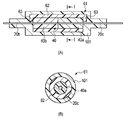
- FIG. 3A is a view showing a gap between a ferrule fixed to the optical fiber connection end of the light guide path of the light source device of the first embodiment and a ferrule fixed to the optical fiber guide light connection end of the light conversion unit.
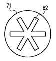
- FIG. 3 (B) shows the end surface of the connection part of the 1st connection part of FIG. 3 (A).
- FIG. 4 is a side view showing a second embodiment of the present invention.
- FIG. 5 is a plan view showing an example of a special screw tool in the third embodiment of the present invention.
- FIG. 6 is a plan view showing another example of a special screw tool.
- FIG. 7 is a side view showing a fourth embodiment of the present invention.
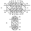
- FIG. 8A is a longitudinal cross-sectional view of the main part showing the connecting portion of the first connection portion of the light source device of the fifth embodiment of the present invention, and FIG.
- FIG. 8B is the view of FIG. It is the II sectional view taken on the line.
- FIG. 9 is a side view showing a schematic configuration of the light source device according to the sixth embodiment of the present invention.
- FIG. 10 (A) is a longitudinal sectional view of the main part showing the connecting part of the first connection part of the light source device of the seventh embodiment of the present invention, and FIG. 10 (B) is the same as FIG. 10 (A). It is II-II sectional view taken on the line.
- FIG. 11 is a side view showing a schematic configuration of a light source device according to an eighth embodiment of the present invention.
- FIG. 12 (A) is a longitudinal sectional view of the main part showing the connecting part of the first connecting part of the light source device of the ninth embodiment of the present invention, and FIG. 12 (B) is the same as FIG. 12 (A).
- FIG. FIG. 13 is a side view showing a schematic configuration of a light source device according to a tenth embodiment of the present invention.
- FIG. 1A, 1B to 3A, 3B show a first embodiment of the present invention.
- This embodiment shows an example in which the light source device 5 of the present invention shown in FIG. 2 is incorporated in the lighting device 1 such as the lighting stand shown in FIG.
- a shaft body 3 that can be flexibly deformed is erected on a base 2.
- An illumination light emitting unit 4 is disposed at the upper end of the shaft body 3.
- the shaft body 3 is formed of, for example, a flexible pipe. By extending and contracting the flexible pipe, the illumination light emitting portion 4 can be directed in an arbitrary direction by curving the shaft body 3.
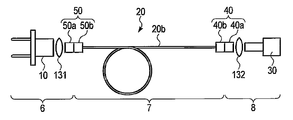
- FIG. 2 shows a schematic configuration of the light source device 5 according to the present embodiment.
- the light source device 5 includes a primary light source 10, a light guide path 20, and a conversion unit 30 as a basic configuration.
- the primary light source 10 emits primary light.
- the light conversion unit 30 converts the optical properties of the primary light and emits it as secondary light.
- the light conversion unit 30 converts at least one of the peak wavelength, spectrum shape, and radiation angle of the primary light and emits it as secondary light.
- the light guide 20 is composed of a long optical fiber that guides the primary light emitted from the primary light source 10 to the light conversion unit 30.
- the primary light source 10 is incorporated in a primary light source module 6 described later.
- the light conversion unit 30 is incorporated in a light conversion module 8 described later.
- An optical fiber module 7 described later is disposed between the primary light source module 6 and the light conversion module 8.
- the light guide part 20 is provided with two connection parts (first connection part 40 and second connection part 50).
- the 1st connection part 40 connects the light guide part 20 and the light conversion unit 30 so that attachment or detachment is possible, and the 2nd connection part 50 can attach or detach the primary light source 10 and light guide part 20 between them.
- the first connection unit 40 is provided with a light conversion unit side connector 40a and a light guide unit side connector 40b. And the optical conversion unit side connector 40a and the light guide part side connector 40b are connected so that attachment or detachment is possible.
- the second connection part 50 is provided with a primary light source side connector 50a and a light guide part side connector 50b. And the primary light source side connector 50a and the light guide part side connector 50b are detachably connected.
- the primary light source module 6 includes a first optical fiber 20 a connected to the primary light source 10, the light guide 20 includes a second optical fiber 20 b, and the light conversion module 8 includes a light conversion unit 30.
- a third optical fiber 20c connected to the.
- the primary light source module 6 includes a primary light source 10, a first optical fiber 20 a, and a primary light source 10 side connector 50 a of the second connection unit 50.
- a primary light source 10 for example, a semiconductor laser can be used.
- the primary light source 10 is formed by a blue semiconductor laser having a wavelength of 450 nm, for example. By using the semiconductor laser, the primary light can be efficiently incident on the first optical fiber 20a.
- the primary light source 10 is connected to one end of the first optical fiber 20a. At the other end of the first optical fiber 20a, a primary light source side connector 50a of the second connection portion 50 is provided.
- the primary light source module 6 is fixed to the housing or the like of the base 2 of the lighting device 1.
- the housing of the base 2 of the lighting device 1 has the primary light source 10 side connector 50a fixed to the upper center portion of the base body 2a formed by a light blocking member that blocks the transmission of laser light. . That is, the primary light source 10, the first optical fiber 20 a, and the primary light source 10 side connector 50 a are fixed to the base body 2 a that is a casing of the common base 2. Accordingly, the first optical fiber 20a is configured not to bend when the light source device 5 is used.
- the light conversion module 8 includes a light conversion unit 30, a third optical fiber 20 c, and a light conversion unit side connector 40 a of the first connection unit 40.
- the light conversion unit 30 has a function of converting at least one of the optical properties of the primary light, for example, the peak wavelength, the spectrum shape, and the radiation angle of the primary light.
- a light diffusion unit that widens the radiation angle of the primary light
- a phosphor unit that converts all of the peak wavelength, the spectrum shape, and the radiation angle can be used as the light conversion unit 30, a light diffusion unit that widens the radiation angle of the primary light, a phosphor unit that converts all of the peak wavelength, the spectrum shape, and the radiation angle can be used.
- the light conversion unit 30 is connected to one end of the third optical fiber 20c.
- the optical conversion unit side connector 40a is provided at the other end of the third optical fiber 20c.
- the light conversion module 8 is fixed to a common housing of the illumination light emitting unit 4 of the illumination device 1.
- the light conversion unit side connector 40a is fixed to the central portion of the lower end of the illumination light emitting part cover 4a that transmits the illumination light. That is, the light conversion unit 30, the third optical fiber 20 c, and the light conversion unit side connector 40 a of the first connection unit 40 are the illumination light emitting unit cover 4 a that is a common housing for the illumination light emitting unit 4. It is fixed to.
- the third optical fiber 20c is configured not to bend when the light source device 5 is used.
- the optical fiber module 7 includes a long flexible second optical fiber 20b, a light guide unit side connector 50b fixed to one end of the second optical fiber 20b, and a second optical fiber 20b. And a light guide unit side connector 40b fixed to the other end.
- the optical fiber module 7 is incorporated in the shaft body 3 of the illumination device 1.
- the light guide unit side connector 50b is fixed to the lower end portion of the shaft body 3, and the light guide unit side connector 40b is fixed to the upper end portion.
- the second optical fiber 20b can be bent together with the shaft body 3 when the shaft body 3 of the illumination device 1 is bent in an arbitrary direction by an external operation. It has become. Thereby, it is comprised so that especially the light conversion unit 30 which is the front-end
- the light source device 5 is configured by combining the primary light source module 6, the optical fiber module 7, and the light conversion module 8 described above.
- the primary light source 10 is a blue semiconductor laser having a wavelength of 450 nm.
- the light conversion unit 30 is configured to efficiently emit bright white light by using a phosphor such as YAG; Ce that absorbs blue light and emits yellow light.
- the light source device 5 has two connection portions (first connection portion 40 and second connection portion 50). Between the 2nd optical fiber 20b and the 3rd optical fiber 20c, the optical conversion unit side connector 40a and the light guide part side connector 40b are connected so that attachment or detachment is possible as the 1st connection part 40. Between the first optical fiber 20a and the second optical fiber 20b, a primary light source 10 side connector 50a and a light guide unit side connector 50b are detachably connected as a second connection unit 50.
- the second connection part 50 provided between the primary light source module 6 and the optical fiber module 7 is a connection part that can be used for purposes other than repair. That is, the second connection unit 50 is a connection unit that can be used by the end user. For example, in order to obtain illumination light according to the purpose, any primary light source module 6 and any light conversion module 8 can be used for replacement and connection. For this reason, the second connection portion 50 includes a shutter (not shown) so that the primary light does not leak outside even when the connection between the primary light source side connector 50a and the light guide portion side connector 50b is removed. Safety measures such as primary light source interlock system are taken. That is, the second connection unit 50 is configured to have a higher safety level than the first connection unit 40.
- the first connection portion 40 between the light conversion module 8 and the optical fiber module 7 is a connection portion used only during repair and maintenance and manufacture of the light source device 5. That is, the end user does not attach or detach the first connection part 40, but a person who has knowledge and skills for ensuring the safety of primary light, such as a person in charge of manufacturing and repair, uses the environment and equipment accordingly. It is a connection part for attaching and detaching. Therefore, unlike the second connection portion 50, the first connection portion 40 itself has no safety measures. Furthermore, since the first connection portion 40 is provided on the distal end side of the optical fiber module 7, it is inserted into the inside of the observation object, for example, a tube during observation. Therefore, it is necessary to make it thin and small. Therefore, the area of the cut surface of the first connection portion 40 cut by a plane orthogonal to the light guide direction of the primary light is configured to be smaller than that of the second connection portion 50.
- the first connection unit 40 has an access restriction that prevents the user from accidentally removing it.
- An example of access restriction is to prevent the tool 64 from being removed unless the tool 64 is used.
- the first connecting portion 40 is formed with an access restricting portion 61 for restricting the tool type access so as not to be easily removed by a user operation during use of the light source device 5.
- FIG. 3A is a cross-sectional view illustrating an example of the access restriction unit 61 of the first connection unit 40.
- the light conversion unit side connector 40a and the light guide unit side connector 40b of the first connection unit 40 are configured as ferrules, for example, and the first connection unit 40 is configured as described above. It is a small connector in which the connectors 40a and 40b are inserted and connected to the inside of the cylindrical sleeve 62.
- the sleeve 62 is bent and deformed substantially at right angles toward the center of the sleeve 62 as shown in FIG. 3B, and the light conversion unit side connector 40 a of the second connection portion 50 and the light guide.
- An engaging protrusion 63 for fixing is provided to lock the part-side connector 40b in a connected state. These engaging projections 63 hold the connectors 40a and 40b so that the light conversion unit side connector 40a and the light guide unit side connector 40b of the first connecting portion 40 are not easily detached from the sleeve 62.
- the ferrule of the light conversion unit side connector 40a or the light guide unit side connector 40b of the first connection portion 40 is sleeved by an access restriction releasing operation for deforming the engagement protrusion 63 by using a tool 64 or the like as necessary. It can be removed from 62. Thereby, the access restriction of the access restriction part 61 is released by a predetermined access restriction release work, and the attachment / detachment work between the light conversion unit side connector 40a and the light guide part side connector 40b of the first connection part 40 becomes possible. To do.
- the second connection portion 50 is configured to have higher resistance to repeated attachment and detachment than the first connection portion 40, and has high wear resistance in a contact region that comes into contact and slides during attachment and detachment operations. It is configured.
- the operation of the light source device 5 having the above configuration will be described.
- the user supplies power to the primary light source 10 from a power source (not shown) to emit primary light.
- the primary light emitted from the primary light source 10 enters the first optical fiber 20 a and is guided to the primary light source side connector 50 a of the second connection unit 50.
- the first optical fiber 20a of the primary light source side connector 50a and the second optical fiber 20b of the light guide unit side connector 50b are optically connected, and the first optical fiber is connected.
- the primary light guided by 20a is incident on the second optical fiber 20b.
- the primary light incident on the second optical fiber 20b is guided to the first connection portion 40 by the second optical fiber 20b.
- the second optical fiber 20b of the light guide unit side connector 40b and the third optical fiber 20c of the light conversion unit side connector 40a are optically connected, and the second optical fiber is connected.
- the primary light guided by 20b enters the third optical fiber 20c.
- the primary light incident on the third optical fiber 20c is guided to the light conversion unit 30 by the third optical fiber 20c.
- the light conversion unit 30 converts the guided primary light into light and emits it as secondary illumination light.
- the illumination light is obtained by bending the shaft body 3 by expanding and contracting the flexible pipe of the shaft body 3. Illuminate the emitting unit 4 in a desired direction.
- the second optical fiber 20b bends together with the shaft body 3 when the shaft body 3 of the illumination device 1 is bent in an arbitrary direction by an operation from the outside.
- the second optical fiber 20b is bent most frequently. It is. Therefore, there is a high possibility that the optical fiber breakage due to repeated bending occurs in the second optical fiber 20b.
- the user removes the second connection part 50 between the primary light source module 6 and the optical fiber module 7, and removes the optical fiber module 7 and the optical conversion module 8. Make a repair request to the person in charge of repair in the connected state.
- the repair person who has received the repair request has an access restriction unit 61 of the first connection unit 40 using a tool 64 or the like suitable for the access restriction release work in an environment suitable for the repair work.
- An access restriction releasing operation for deforming the engaging protrusion 63 is performed.
- the ferrule of the light conversion unit side connector 40a and the ferrule of the light guide unit side connector 40b of the first connection part 40 can be detached from the sleeve 62. Thereby, the optical fiber module 7 and the optical conversion module 8 are separated by the first connecting portion 40.
- the worker After separating the optical fiber module 7 and the optical conversion module 8, the worker connects the new optical fiber module 7 to the first connection unit 40, and completes the repair.
- the optical conversion module 8 fails, the user removes the second connection part 50 between the primary light source module 6 and the optical fiber module 7, and the optical fiber module 7 and the optical conversion module 8 A repair request is made to a repair person or the like in a state in which is connected. Therefore, the worker in charge of repairing the light conversion of the first connection portion 40 by deforming the engagement protrusion 63 of the access restriction portion 61 of the first connection portion 40 using the tool 64 or the like as described above.
- the ferrule of the unit side connector 40a and the ferrule of the light guide unit side connector 40b are removed from the sleeve 62. Thereby, the optical fiber module 7 and the light conversion module 8 are separated by the first connection part 40, and the new light conversion module 8 is connected to the first connection part 40 to complete the repair.
- the user removes the primary light source module 6 with the second connection unit 50 and requests a repair person or the like to repair the primary light source module 6.
- the person in charge of repair determines the state of the primary light source module 6 and repairs or replaces it.
- the position of the 1st connection part 40 can be selected appropriately so that the part of the optical fiber module 7 with the highest possibility of failure can be easily replaced.
- the light source device 5 having the above configuration has the following effects. That is, in the light source device 5 of the present embodiment, two connection portions (the first connection portion 40 and the second connection portion 50) are provided on the light guide portion 20. Thereby, when a failure occurs in the light source device 5, the first connection portion 40 and the second connection portion 50 are removed, and the portion where the failure has occurred (for example, the second optical fiber 20b of the failed optical fiber module 7). ) Can be removed and only that part can be replaced. As a result, repair can be easily performed.
- the optical conversion unit 30 of the optical conversion module 8 or the primary light source 10 of the primary light source module 6 is expensive. New parts can be reused without replacement. Therefore, the member cost at the time of repairing the light source device 5 can be reduced.
- the first optical fiber 20a of the primary light source module 6 and the third optical fiber 20c of the light conversion module 8 are configured so as not to bend when the light source device 5 is used. The possibility that the fiber 20a or the third optical fiber 20c is damaged is low. Further, the first optical fiber 20a of the primary light source module 6 and the third optical fiber 20c of the light conversion module 8 are arranged in the housing so that the length of the optical fiber is shortened and not exposed to the outside. Because of the configuration, the optical fibers 20a and 20c are not exposed to the outside of the module. Thereby, the possibility of damaging the first optical fiber 20a of the primary light source module 6 and the third optical fiber 20c of the light conversion module 8 during manufacturing or repair can be reduced.
- the first connection unit 40 that removably connects the light guide unit 20 and the light conversion unit 30 prohibits the attachment / detachment operation between the light guide unit 20 and the light conversion unit 30.
- the access restriction unit 61 is provided, and the access restriction of the access restriction unit 61 is released by a predetermined access restriction release operation so that the attachment / detachment operation between the light guide unit 20 and the light conversion unit 30 is enabled. Yes. Therefore, since it can be regulated so that the end user does not attach or detach the first connecting portion 40, the operation of attaching or detaching the first connecting portion 40 is the safety of the primary light such as a manufacturing or repair person.
- the light source device 5 can be repaired by a correct procedure so that a person who has knowledge and skills for securing can attach and detach using the environment and equipment corresponding to it.
- the light source device 5 that can be easily repaired can be provided.
- the second connection unit 50 is configured to be usable by the user, and the first connection unit 40 is configured not to be used by the user.
- the present invention is not limited to this.
- both the first and second connection portions 40 and 50 can be prevented from being used by the user. By comprising in this way, it becomes unnecessary to take a safety measure etc. to both the 1st, 2nd connection parts 40 and 50, and the cheap light source device 5 can be provided.
- both the first and second connection portions 40 and 50 can be used by the user. With this configuration, at the time of repair, the user only has to hand over the smallest unit to the person in charge of manufacturing and repair. In addition, if it is only exchange, the user can implement it.
- FIG. 4 shows a second embodiment.
- This embodiment is a first modification of the access restriction unit 61 in the first connection unit 40 of the light source device 5 of the first embodiment.
- the access restricting portion 61 of the first connecting portion 40 of the present modification includes a cylindrical sleeve 62 and male screws 71 provided respectively at the joint between the light conversion unit side connector 40a and the light guide portion side connector 40b. It is to be prepared.
- the head of the male screw 71 is provided with a plus-type engagement groove 72 that engages with a plus driver (not shown).
- the optical conversion unit side connector 40a of the first connecting portion 40 and the light guide are removed by an access restriction releasing operation in which a positive driver (not shown) is engaged with the positive engagement groove 72 of the male screw 71 and the male screw 71 is removed.
- the ferrule of the part side connector 40b can be removed from the sleeve 62.
- a minus-type engagement groove and a minus driver may be used instead of the plus-type engagement groove 72 and the plus driver.
- FIG. 5 and 6 show a third embodiment.
- This embodiment is a second modification of the access restriction unit 61 in the first connection unit 40 of the light source device 5 of the first embodiment.
- the access restricting portion 61 of the first connecting portion 40 of the present modification is attached to each of a joining portion between the cylindrical sleeve 62 and the light conversion unit side connector 40a and a joining portion between the sleeve 62 and the light guide portion side connector 40b.
- the male screw 71 is a special screw. That is, a special screw in which a triangular recess 81 is formed as shown in FIG. 5 or a special-shaped groove 82 in which three linear grooves are crossed is formed in the head of the male screw 71 as shown in FIG. Special screws are used.
- the access restriction unit 61 is a tool type access restriction having a tip structure of a special tool and a special screw fitting structure corresponding to the special tool.
- the screw to be used may be a reverse screw that can be removed by rotating it in the opposite direction.
- a two-action connector such as pushing and turning. At this time, if the screw is rotated in the reverse direction of the normal direction after being pushed in and fixed with the screw, the access is more reliably restricted.
- FIG. 7 shows a fourth embodiment.
- This embodiment shows a third modification of the access restriction unit 61 in the first connection unit 40 of the light source device 5 of the first embodiment.
- the access restricting portion 61 of the first connecting portion 40 of the present modification is an outer peripheral surface of a cylindrical sleeve 62 that is externally fitted to the light conversion unit side connector 40a and the light guide portion side connector 40b.
- a display 91 for displaying a warning display for example, a character or symbol such as “Prohibit removal except during maintenance” can be used.
- the first connection unit 40 is configured to have a high access restriction level so that the first connection unit 40 cannot be easily removed as compared with the second connection unit 50.
- FIGS. 1A, 1B to 3A, 3B show a fifth embodiment.
- This embodiment is an access restriction unit in the first connection unit 40 of the light source device 5 of the first example (see FIGS. 1A, 1B to 3A, 3B). It is the modification which changed the structure of 61 as follows. The same parts as those in the first embodiment are denoted by the same reference numerals, and the description thereof is omitted. Only different points will be described here.
- a cover 101 is provided as a protective member covering the outer peripheral surface of the sleeve 62 and its vicinity as the access restricting portion 61 in the first connecting portion 40 of the first embodiment.
- the cover 101 is made of a rubber having a waterproof property, and can reduce the connection loss of the optical fiber caused by dust and moisture entering the first connection portion 40. Further, it is desirable that the cover 101 has not only waterproofness but also heat resistance and impact resistance.
- the first connection portion 40 is inserted into the interior of the illumination object, so that it is waterproof and heat resistant compared to the second connection portion 50 so as not to select the illumination object. It is constructed with high impact resistance.
- a knowledgeable worker uses a necessary tool to remove the cover 101, and then removes the first connecting portion 40 in the same procedure as in the first embodiment. Further, after the repair, a new cover 101 is attached to the first connection portion 40.
- the cover 101 is provided as a protective member that covers the sleeve 62 of the access restricting portion 61 in the first connecting portion 40 and the outer peripheral surface of the vicinity thereof, the user accidentally enters the first It is difficult for the first connecting portion 40 to be detached due to physical impact or the like. Furthermore, since it is possible to prevent dust, moisture, and the like from entering the first connection portion 40 by the cover 101, it is possible to prevent a connection loss from being lowered.
- the user does not accidentally remove the first connection portion 40 for which safety measures are not taken, or the first connection portion 40 is not detached due to a physical shock.
- the risk of primary light irradiation to the user can be reduced.
- ferrules of the light conversion unit side connector 40a and the light guide unit side connector 40b and the sleeve 62 are not exposed to the outside, members can be selected by function without considering environmental resistance. For example, a glass ferrule that is easily broken can be used as necessary.
- FIG. 9 shows a sixth embodiment of the present invention.
- This embodiment is a modification of the light source device 5 of the fifth embodiment (see FIGS. 8A and 8B).
- the cover 101 is provided only around the first connecting portion 40 is shown, but in the present embodiment, the cover 111 as a protective member is entirely formed from the optical conversion module 8 to the optical fiber module 7. It is comprised so that it may be covered with.
- FIG. 9 shows an example in which a cover 111 as an access restriction unit is provided in a state where the optical fiber module 7 and the optical conversion module 8 are connected.
- the light conversion unit 8 the light conversion unit 30, the third optical fiber 20 c, and the light conversion unit side connector 40 a of the first connection unit 40 are a common housing of the illumination light emitting unit 4 of the lighting device 1. Is attached.
- the optical conversion module 8 and the optical fiber module 7 are covered with a cover 111 as a common protective member in a connected state.
- the cover 111 may be a rubber having a waterproof property, or may be a heat-resistant coat having a heat resistance. Further, a cushioning material having excellent impact resistance may be used.
- the example in which the cover 111 serving as one access restriction unit is provided for one first connection unit 40 is not limited thereto.
- one cover 121 may be provided for the two first connecting portions 40 as in the seventh embodiment shown in FIGS. It is also preferable to provide one cover for three or more first connection portions 40. At this time, it is desirable that the distance between the plurality of light guide paths in the first connection portion 40 is narrow, and the degree of integration is increased.
- a so-called multi-core connector having a function of connecting a plurality of light guide paths to one first connecting portion 40 can be used. Also in this case, it is desirable that the distance between the plurality of light guide paths is narrow and the degree of integration is increased.
- the distance between the plurality of light guide paths compared to the second connection portion 50 so as not to select the illumination object is: It is desirable to be narrow and configured to increase the degree of integration.
- connection portion 40 an example having two connection portions (the first connection portion 40 and the second connection portion 50) is shown, but the present invention is not limited thereto.
- optical fiber 20b When the optical fiber 20b is very long or when there are a plurality of bent portions, two or more connecting portions can be provided. As a result, only the damaged optical fiber 20b can be replaced and repaired.
- FIG. 11 shows an eighth embodiment of the present invention.
- the configurations of the primary light source module 6 and the light conversion module 8 are changed from those of the first embodiment. That is, instead of the first optical fiber 20a provided in the primary light source module 6 of the first embodiment, in this embodiment, a lens or the like is provided between the primary light source 10 and the primary light source side connector 50a.
- the optical connection part 131 composed only of the optical system is provided.
- a lens or the like is provided between the light conversion unit 30 and the light conversion unit side connector 40a.
- the optical connection part 132 comprised only of these optical systems is provided.
- the use of the optical fibers 20a and 20c can be omitted by using the optical connection portions 131 and 132 in both the primary light source module 6 and the light conversion module 8.
- FIG. 12A shows a peripheral portion of the first connection portion 40 of the light source device 5.
- the second device 141 such as an imaging device, for example, only the electric wiring 142 without a connection portion is arranged.
- the electrical wiring 142 of the second device 141 is arranged in parallel around the first connection portion 40 of the light source device 5, and the first connection portion 40 of the light source device 5 and the second device are arranged.
- One cover 143 is provided as a protective member for protecting the electrical wiring 142 of 141 together.
- the second device 141 used together with the light source device 5 can be protected together by one cover 143, the second device 141 used together with the light source device 5 is also combined with environmental performance. Can be improved.
- FIG. 13 shows a tenth embodiment of the present invention.
- This embodiment is a configuration example when the light source device 5 is used in combination with, for example, a second device 152 such as an endoscope having an elongated insertion portion 151 inserted into a tube.
- a second device 152 such as an endoscope having an elongated insertion portion 151 inserted into a tube.
- the second device 152 is provided with a hard tip rigid portion 153 at the tip of the insertion portion 151.
- the distal end rigid portion 153 is provided with an illumination portion 154 that is the light conversion unit 30 and an observation portion 155.
- the observation unit 155 is provided with an image sensor such as a CCD.
- the electrical wiring 156 of the imaging element of the observation unit 155 passes through the insertion unit 151 and is connected to an external camera control unit (CCU) 157 connected to the proximal end of the insertion unit 151.
- CCU camera control unit
- the light conversion module 8 is assembled to the distal end rigid portion 153, and the optical fiber module 7 is assembled to the insertion portion 151 of the second device 152.
- the light conversion module 8 and the optical fiber module 7 of the light source device 5 are integrally assembled with the insertion portion 151 of the second device 152, an insertion operation for inserting the insertion portion 151 into the tube is also performed.
- advantages such as easy to use and easy to share environmental resistance.
- the present invention illuminates the secondary light by guiding the primary light emitted from the primary light source to a light conversion unit that converts the optical properties of the primary light and generates secondary light through the light guide path. This is effective in a technical field that uses a light source device that emits light to the outside and a technical field that manufactures it.
Landscapes
- Health & Medical Sciences (AREA)
- Life Sciences & Earth Sciences (AREA)
- Physics & Mathematics (AREA)
- Surgery (AREA)
- Optics & Photonics (AREA)
- Engineering & Computer Science (AREA)
- Heart & Thoracic Surgery (AREA)
- Medical Informatics (AREA)
- Biophysics (AREA)
- Nuclear Medicine, Radiotherapy & Molecular Imaging (AREA)
- Pathology (AREA)
- Radiology & Medical Imaging (AREA)
- Veterinary Medicine (AREA)
- Biomedical Technology (AREA)
- Public Health (AREA)
- General Health & Medical Sciences (AREA)
- Molecular Biology (AREA)
- Animal Behavior & Ethology (AREA)
- General Physics & Mathematics (AREA)
- Astronomy & Astrophysics (AREA)
- General Engineering & Computer Science (AREA)
- Optical Couplings Of Light Guides (AREA)
- Endoscopes (AREA)
- Instruments For Viewing The Inside Of Hollow Bodies (AREA)
Abstract
1次光を射出する1次光源(10)を有する1次光源モジュール(6)と、前記1次光源から出射される1次光の光学的性質を変換し、2次光を生成する光変換ユニット(30)を有する光変換モジュール(8)と、前記1次光源モジュールと前記光変換モジュールとの間に配設され、前記1次光源から出射される1次光を前記1次光源モジュールから前記光変換モジュールに導光する導光部(20)と、前記光変換モジュールと導光部との間を着脱可能に接続する第1の接続部(40)と、前記1次光源モジュールと導光部との間を着脱可能に接続する第2の接続部(50)と、を有する。
Description
本発明は、光源から射出された光が導光路を使用して導光される光源装置に関する。
照明光を放射する光源装置の先行技術が、例えば特許文献1に記載されている。特許文献1では、レーザ光源と、光ファイバからなるライトガイドと、波長変換部材と、により構成されている発光ユニットを備えた発光装置が提案されている。ここでは、光ファイバからなるライトガイドの基端部に青色レーザ光源が、ライトガイドの先端部に波長変換部材が、それぞれ配設されている。そして、青色レーザ光源から射出されたレーザ光(1次光)をライトガイドで先端まで導光し、ライトガイドの先端の波長変換部材で波長変換した2次光が照明光として外部に出射される構成になっている。
この光源装置は、例えば内視鏡などに搭載される。この内視鏡で狭い空間に発光部 (波長変換部材)を挿入し、狭い空間の内部を照明するようになっている。
上記特許文献1では、内視鏡などに光源装置が搭載され、内視鏡で狭い空間に発光部(波長変換部材)を挿入し、狭い空間の内部を照明する。この場合、内視鏡が狭い空間内部に挿入される操作時には、挿入される空間内部の形状に合わせて内視鏡の形状が変形するので、このときの内視鏡の形状に応じてライトガイドの形状を変形させる必要がある。このようにライトガイドの形状の変形等を繰り返し行なった場合には、光ファイバが破損する可能性がある。光ファイバが破損した場合、レーザ光源から射出されたレーザ光は、ライトガイドの先端部に設けられた波長変換部材に届かなくなり、光源装置は発光できなくなる。
そして、上記特許文献1の光源装置の修理を行う場合には、破損した光ファイバの一端側をレーザ光源から取り外すとともに、他端側を波長変換部材から取り外す作業が必要になる。さらにその後、新しい光ファイバの一端側をレーザ光源に取り付け、さらに該新しい光ファイバの他端側を波長変換部材に取り付ける作業が必要になる。そのため、光ファイバの交換時の修理の手間が大きかった。
特に、狭い管内を照明するような細径な光源装置では、波長変換部材を細径に構成する必要がある。この場合、波長変換部材を再利用することが難しく、波長変換部材を新品に交換する必要もあり、コスト高になる。
さらに、波長変換部材が劣化した場合や、レーザ光源装置が劣化した場合にも同様に、光ファイバの着脱作業が必要になる問題がある。すなわち、従来技術の光源装置は、修理に手間の掛かる構成であった。
本発明は上記事情に着目してなされたもので、その目的は、装置の一部に故障が生じた場合にも、安全かつ容易に修理が可能な光源装置を提供することにある。
本発明の一態様によれば、
1次光を射出する1次光源を有する1次光源モジュールと、
前記1次光源から出射される1次光の光学的性質を変換し、2次光を生成する光変換ユニットを有する光変換モジュールと、
前記1次光源モジュールと前記光変換モジュールとの間に配設され、前記1次光源から出射される1次光を前記1次光源モジュールから前記光変換モジュールに導光する導光路と、
前記光変換モジュールと前記導光路との間を着脱可能に接続する第1の接続部と、
前記1次光源モジュールと前記導光路との間を着脱可能に接続する第2の接続部と、
を有することを特徴とする光源装置が提供される。
1次光を射出する1次光源を有する1次光源モジュールと、
前記1次光源から出射される1次光の光学的性質を変換し、2次光を生成する光変換ユニットを有する光変換モジュールと、
前記1次光源モジュールと前記光変換モジュールとの間に配設され、前記1次光源から出射される1次光を前記1次光源モジュールから前記光変換モジュールに導光する導光路と、
前記光変換モジュールと前記導光路との間を着脱可能に接続する第1の接続部と、
前記1次光源モジュールと前記導光路との間を着脱可能に接続する第2の接続部と、
を有することを特徴とする光源装置が提供される。
本発明によれば、装置の一部に故障が生じた場合にも、安全かつ容易に修理が可能な光源装置を提供することができる。
以下、本発明の実施例を、図面を参照して説明する。
[第1実施例]
図1(A),図1(B)乃至図3(A),図3(B)は、本発明の第1実施例を示す。本実施例は、図2に示す本発明の光源装置5を図1(A)に示す照明スタンドなどの照明装置1に組み込んだ例を示す。この照明装置1は、基台2上にフレキシブルに変形可能な軸体3が立設されている。軸体3の上端部には、照明光出射部4が配設されている。
図1(A),図1(B)乃至図3(A),図3(B)は、本発明の第1実施例を示す。本実施例は、図2に示す本発明の光源装置5を図1(A)に示す照明スタンドなどの照明装置1に組み込んだ例を示す。この照明装置1は、基台2上にフレキシブルに変形可能な軸体3が立設されている。軸体3の上端部には、照明光出射部4が配設されている。
軸体3は、例えばフレキシブルパイプによって形成されている。このフレキシブルパイプを伸縮することにより、軸体3を湾曲させることで照明光出射部4を任意の方向に向けることができる。
図2は、本実施例による光源装置5の概略構成を示す。本実施例による光源装置5は、基本構成として、1次光源10、導光路20及び変換ユニット30を備えている。1次光源10は、1次光を発光する。光変換ユニット30は、1次光の光学的性質を変換して2次光として射出する。ここで、光変換ユニット30は、1次光のピーク波長、スペクトル形状、放射角の少なくとも一つを変換して2次光として射出する。導光路20は、1次光源10から射出された1次光を光変換ユニット30まで導光する長尺の光ファイバからなる。
上記1次光源10は、後述する1次光源モジュール6に組み込まれている。上記光変換ユニット30は、後述する光変換モジュール8に組み込まれている。1次光源モジュール6と光変換モジュール8との間には後述する光ファイバモジュール7が配設されている。
導光部20には、2箇所の接続部(第1の接続部40および第2の接続部50)が設けられている。第1の接続部40は、導光部20と光変換ユニット30との間を着脱可能に接続し、第2の接続部50は、1次光源10と導光部20との間を着脱可能に接続する。ここで、第1の接続部40には、光変換ユニット側コネクタ40aと、導光部側コネクタ40bとが設けられている。そして、光変換ユニット側コネクタ40aと、導光部側コネクタ40bとが着脱可能に接続されるようになっている。同様に、第2の接続部50には、1次光源側コネクタ50aと、導光部側コネクタ50bとが設けられている。そして、1次光源側コネクタ50aと、導光部側コネクタ50bとが着脱可能に接続されるようになっている。
また、1次光源モジュール6は、1次光源10に接続された第1の光ファイバ20aを備え、導光路20は、第2の光ファイバ20bを備え、光変換モジュール8は、光変換ユニット30に接続された第3の光ファイバ20cを備える。
以下、各部の構成をより詳細に説明する。
[1次光源モジュール]
1次光源モジュール6は、1次光源10と、第1の光ファイバ20aと、第2の接続部50の1次光源10側コネクタ50aと、により構成されている。1次光源10は、例えば半導体レーザを用いることができる。本実施例では、1次光源10は、例えば波長450nmの青色半導体レーザによって形成されている。半導体レーザを用いることで、1次光を効率よく第1の光ファイバ20aに入射させることができる。
1次光源モジュール6は、1次光源10と、第1の光ファイバ20aと、第2の接続部50の1次光源10側コネクタ50aと、により構成されている。1次光源10は、例えば半導体レーザを用いることができる。本実施例では、1次光源10は、例えば波長450nmの青色半導体レーザによって形成されている。半導体レーザを用いることで、1次光を効率よく第1の光ファイバ20aに入射させることができる。
1次光源10は、第1の光ファイバ20aの一端に接続されている。第1の光ファイバ20aの他端には第2の接続部50の1次光源側コネクタ50aが設けられている。1次光源モジュール6は、照明装置1の基台2の筐体等に固定されている。ここで、照明装置1の基台2の筐体は、レーザ光の透過を遮光する遮光部材によって形成されている基台本体2aの上端中央部位に1次光源10側コネクタ50aが固定されている。すなわち、1次光源10と、第1の光ファイバ20aと、1次光源10側コネクタ50aとは、共通の基台2の筐体である基台本体2aに固定されている。これにより、第1の光ファイバ20aは、光源装置5の使用時には屈曲しないように構成されている。
[光変換モジュール]
光変換モジュール8は、光変換ユニット30と、第3の光ファイバ20cと、第1の接続部40の光変換ユニット側コネクタ40aと、により構成されている。光変換ユニット30は、1次光の光学的性質、例えば、1次光のピーク波長、スペクトル形状、放射角の少なくとも一つを変換する機能を有している。例えば、光変換ユニット30としては、1次光の放射角を広げる光拡散ユニットや、ピーク波長、スペクトル形状及び放射角の全てを変換する蛍光体ユニット、などを用いることができる。
光変換モジュール8は、光変換ユニット30と、第3の光ファイバ20cと、第1の接続部40の光変換ユニット側コネクタ40aと、により構成されている。光変換ユニット30は、1次光の光学的性質、例えば、1次光のピーク波長、スペクトル形状、放射角の少なくとも一つを変換する機能を有している。例えば、光変換ユニット30としては、1次光の放射角を広げる光拡散ユニットや、ピーク波長、スペクトル形状及び放射角の全てを変換する蛍光体ユニット、などを用いることができる。
光変換ユニット30は、第3の光ファイバ20cの一端に接続されている。第3の光ファイバ20cの他端には、光変換ユニット側コネクタ40aが設けられている。また、光変換モジュール8は、照明装置1の照明光出射部4の共通の筐体に固定されている。ここで、照明光出射部4は、照明光を透過する照明光出射部カバー4aの下端中央部位に光変換ユニット側コネクタ40aが固定されている。すなわち、光変換ユニット30と、第3の光ファイバ20cと、第1の接続部40の光変換ユニット側コネクタ40aとは、照明光出射部4の共通の筐体である照明光出射部カバー4aに固定されている。これにより、第3の光ファイバ20cは、光源装置5の使用時において、屈曲しないように構成されている。
[光ファイバモジュール]
光ファイバモジュール7は、長尺な可撓性を有する第2の光ファイバ20bと、この第2の光ファイバ20bの一端に固定された導光部側コネクタ50bと、第2の光ファイバ20bの他端に固定された導光部側コネクタ40bと、により構成されている。この光ファイバモジュール7は、照明装置1の軸体3内に組み込まれている。ここで、軸体3の下端部には、導光部側コネクタ50bが固定され、上端部には導光部側コネクタ40bが固定されている。そして、第2の光ファイバ20bは、光源装置5の使用時に、外部からの操作により照明装置1の軸体3が任意の方向に湾曲操作される際に、軸体3と一緒に湾曲可能になっている。これにより、特に、外部からの操作により光源装置5の先端部である光変換ユニット30を、照明したい方向に向けることができるように構成されている。
光ファイバモジュール7は、長尺な可撓性を有する第2の光ファイバ20bと、この第2の光ファイバ20bの一端に固定された導光部側コネクタ50bと、第2の光ファイバ20bの他端に固定された導光部側コネクタ40bと、により構成されている。この光ファイバモジュール7は、照明装置1の軸体3内に組み込まれている。ここで、軸体3の下端部には、導光部側コネクタ50bが固定され、上端部には導光部側コネクタ40bが固定されている。そして、第2の光ファイバ20bは、光源装置5の使用時に、外部からの操作により照明装置1の軸体3が任意の方向に湾曲操作される際に、軸体3と一緒に湾曲可能になっている。これにより、特に、外部からの操作により光源装置5の先端部である光変換ユニット30を、照明したい方向に向けることができるように構成されている。
[光源装置]
光源装置5は、上述した1次光源モジュール6と、光ファイバモジュール7と、光変換モジュール8とを組み合わせて構成されている。本実施例では例えば、1次光源10は、波長450nmの青色半導体レーザが使用される。光ファイバ20a、20b、20cは、コア径50μm、クラッド径125μm、NA=0.22のガラス製のステップインデックス型光ファイバが使用される。光変換ユニット30は、青色光を吸収し、黄色光を放射するYAG;Ce等の蛍光体を用いることで、明るい白色光を効率よく射出できるように構成されている。
光源装置5は、上述した1次光源モジュール6と、光ファイバモジュール7と、光変換モジュール8とを組み合わせて構成されている。本実施例では例えば、1次光源10は、波長450nmの青色半導体レーザが使用される。光ファイバ20a、20b、20cは、コア径50μm、クラッド径125μm、NA=0.22のガラス製のステップインデックス型光ファイバが使用される。光変換ユニット30は、青色光を吸収し、黄色光を放射するYAG;Ce等の蛍光体を用いることで、明るい白色光を効率よく射出できるように構成されている。
[接続部]
本実施例による光源装置5では、2箇所の接続部(第1の接続部40および第2の接続部50)を有している。第2の光ファイバ20bと第3の光ファイバ20cとの間は、第1の接続部40として、光変換ユニット側コネクタ40aと導光部側コネクタ40bとが着脱可能に連結されている。第1の光ファイバ20aと第2の光ファイバ20bとの間は、第2の接続部50として、1次光源10側コネクタ50aと導光部側コネクタ50bとが着脱可能に連結されている。
本実施例による光源装置5では、2箇所の接続部(第1の接続部40および第2の接続部50)を有している。第2の光ファイバ20bと第3の光ファイバ20cとの間は、第1の接続部40として、光変換ユニット側コネクタ40aと導光部側コネクタ40bとが着脱可能に連結されている。第1の光ファイバ20aと第2の光ファイバ20bとの間は、第2の接続部50として、1次光源10側コネクタ50aと導光部側コネクタ50bとが着脱可能に連結されている。
ここで、1次光源モジュール6と光ファイバモジュール7との間に設けられた第2の接続部50は、修理以外の目的にも利用可能な接続部である。すなわち、第2の接続部50は、最終ユーザも使用可能な接続部である。例えば、目的に応じた照明光を得るために、任意の1次光源モジュール6と任意の光変換モジュール8とを取り替えて接続するために利用することができる。このため、第2の接続部50には、1次光源側コネクタ50aと導光部側コネクタ50bとの連結を外した場合にも1次光が外部に漏れ出さないように、図示しないシャッタや、1次光源インターロックシステム等の安全策が講じられている。すなわち、第2の接続部50は、第1の接続部40と比較して、安全のレベルが高くなる状態に構成されている。
一方、光変換モジュール8と光ファイバモジュール7との間の第1の接続部40は、修理やメンテナンス、および光源装置5の製造時にのみ用いる接続部である。すなわち、最終ユーザは第1の接続部40を着脱することはなく、製造、修理担当者等、1次光の安全確保のための知識や技能を有する人間が、それに応じた環境、設備を使用して着脱するための接続部である。従って、第2の接続部50とは異なり、第1の接続部40そのものには安全策は講じられていない。さらに、第1の接続部40は、光ファイバモジュール7の先端側に設けられるため、観察時には観察対象物の内部、例えば管内に挿入される。従って、細く、小型に作製する必要がある。そこで、第1の接続部40の、1次光の導光方向と直交する平面により切断した切断面の面積は、第2の接続部50と比べて小さく構成されている。
第1の接続部40は、ユーザが誤って外したりしないようなアクセス制限がなされている。アクセス制限の例としては、例えば、工具64を使用しなければ外れないようにすることである。言い換えると、第1の接続部40は、光源装置5の使用中にユーザの操作により、容易には外れないように工具型アクセス制限がなされるアクセス制限部61が形成されている。
図3(A)は、第1の接続部40のアクセス制限部61の一例を示す断面図である。図3(A)に示すように、第1の接続部40の光変換ユニット側コネクタ40aおよび導光部側コネクタ40bは、例えばフェルール等として構成され、第1の接続部40は、このようなコネクタ40a,40bを円筒状のスリーブ62の内部に挿入して接続するような小型コネクタである。
また、スリーブ62の両端には、図3(B)に示すようにスリーブ62の中心方向に向けてほぼ直角に屈曲変形させて、第2の接続部50の光変換ユニット側コネクタ40aと導光部側コネクタ40bとを連結状態で係止させる、固定用の係合突起63が設けられている。これらの係合突起63は、スリーブ62から第1の接続部40の光変換ユニット側コネクタ40aと導光部側コネクタ40bとが容易には外れないように、それらコネクタ40a,40bを保持する。そして、必要に応じて工具64等の使用により、係合突起63を変形させるアクセス制限解除作業により、第1の接続部40の光変換ユニット側コネクタ40aまたは導光部側コネクタ40bのフェルールをスリーブ62から取り外すことが可能となっている。これにより、所定のアクセス制限解除作業によりアクセス制限部61のアクセス制限を解除して第1の接続部40の光変換ユニット側コネクタ40aと導光部側コネクタ40bとの間の着脱作業を可能にする。
一方、第2の接続部50は、第1の接続部40と比較して、着脱の繰り返しに対する耐性が高く構成されており、着脱作業時に接触して摺りあわされる接触領域の耐摩耗性が高く構成されている。
次に、上記構成の光源装置5の作用について説明する。はじめに、本実施例の光源装置5の基本動作について説明する。光源装置5を使用する場合、ユーザは図示しない電源から1次光源10に電力を供給して1次光を射出させる。1次光源10から射出された1次光は、第1の光ファイバ20aに入射し、第2の接続部50の1次光源側コネクタ50aまで導光される。第2の接続部50では、1次光源側コネクタ50aの第1の光ファイバ20aと導光部側コネクタ50bの第2の光ファイバ20bとが光学的に接続されており、第1の光ファイバ20aにより導光された1次光は第2の光ファイバ20bに入射される。
第2の光ファイバ20bに入射した1次光は、第2の光ファイバ20bにより第1の接続部40まで導光される。第1の接続部40では、導光部側コネクタ40bの第2の光ファイバ20bと光変換ユニット側コネクタ40aの第3の光ファイバ20cとが光学的に接続されており、第2の光ファイバ20bにより導光された1次光は第3の光ファイバ20cに入射される。第3の光ファイバ20cに入射した1次光は、第3の光ファイバ20cにより光変換ユニット30まで導光される。光変換ユニット30は、導光された1次光を光変換して2次光の照明光として外部に放出する。
本発明の光源装置5を図1(A)に示す照明スタンドなどの照明装置1に組み込んで使用する場合、軸体3のフレキシブルパイプを伸縮することにより、軸体3を湾曲させることで照明光出射部4を所望の方向に向けて照明する。このとき、外部からの操作により照明装置1の軸体3が任意の方向に湾曲操作される際に、第2の光ファイバ20bは、軸体3と一緒に湾曲する。
従って、光源装置5の3つの光ファイバ(第1の光ファイバ20aと、第2の光ファイバ20bと、第3の光ファイバ20c)のうち、最も頻繁に屈曲するのは第2の光ファイバ20bである。従って、繰り返しの屈曲を原因とする光ファイバの破損は第2の光ファイバ20bで発生する可能性が高い。例えば、第2の光ファイバ20bが破損した場合、ユーザは、1次光源モジュール6と光ファイバモジュール7との間の第2の接続部50を外し、光ファイバモジュール7と光変換モジュール8とを接続した状態で修理担当者等に修理依頼を行う。
修理依頼を受けた修理担当者は、ふさわしい技能を有する作業者が、修理作業にふさわしい環境下で、アクセス制限解除作業に適した工具64等を用いて第1の接続部40のアクセス制限部61の係合突起63を変形させるアクセス制限解除作業を行う。このアクセス制限解除作業により、第1の接続部40の光変換ユニット側コネクタ40aのフェルールと導光部側コネクタ40bのフェルールとをスリーブ62から取り外すことができる。これにより、第1の接続部40で光ファイバモジュール7と光変換モジュール8とを分離する。
さらに、作業者は、光ファイバモジュール7と光変換モジュール8との分離後、新しい光ファイバモジュール7を第1の接続部40に接続し、修理を完了する。
また、光変換モジュール8が故障した場合も同様に、ユーザは、1次光源モジュール6と光ファイバモジュール7との間の第2の接続部50を外し、光ファイバモジュール7と光変換モジュール8とを接続した状態で修理担当者等に修理依頼を行うことになる。よって、修理担当の作業者は、上述の通り、工具64等を用いて第1の接続部40のアクセス制限部61の係合突起63を変形させることで、第1の接続部40の光変換ユニット側コネクタ40aのフェルールと導光部側コネクタ40bのフェルールとをスリーブ62から取り外す。これにより、第1の接続部40で光ファイバモジュール7と光変換モジュール8とを分離し、新しい光変換モジュール8を第1の接続部40に接続し、修理を完了する。
さらに、1次光源モジュール6が故障した場合、ユーザは1次光源モジュール6を第2の接続部50で取り外し、1次光源モジュール6の修理を修理担当者等に依頼する。修理担当者は1次光源モジュール6の状態を判断し、修理するかまたは交換する。
上記のように構成することで、故障した光ファイバモジュール7の部分のみを容易に取り外し、交換修理することが可能となる。また、最も故障する可能性が高い光ファイバモジュール7の部分を交換し易いように、第1の接続部40の位置を適切に選択することができる。
そこで、上記構成の光源装置5にあっては次の効果を奏する。すなわち、本実施例の光源装置5では、導光部20上に、2箇所の接続部(第1の接続部40と第2の接続部50)を設けている。これにより、光源装置5に故障が生じた場合、第1の接続部40と第2の接続部50をはずし、故障が生じた部分(例えば、故障した光ファイバモジュール7の第2の光ファイバ20b)を取り外し、その部分のみ交換することができる。これにより、修理を容易に行うことが可能となっている。さらに、最も故障し易い光ファイバモジュール7の第2の光ファイバ20bの部分のみを交換できるため、例えば光変換モジュール8の光変換ユニット30や、1次光源モジュール6の1次光源10などの高価な部品は交換せずに、再利用することができる。そのため、光源装置5の修理時の部材コストを軽減することが可能となる。
なお、1次光源モジュール6の第1の光ファイバ20aと、光変換モジュール8の第3の光ファイバ20cとは、光源装置5の使用時には屈曲しないように構成されているので、第1の光ファイバ20aまたは第3の光ファイバ20cが破損する可能性は低い。さらに、1次光源モジュール6の第1の光ファイバ20aおよび光変換モジュール8の第3の光ファイバ20cは、光ファイバの長さを短くし、外部に露出しないように筐体内に配置するように構成しているため、光ファイバ20a、20cがモジュールの外部に露出しない。これにより、製造時や修理時に、1次光源モジュール6の第1の光ファイバ20aおよび光変換モジュール8の第3の光ファイバ20cを破損する可能性を軽減できる。
したがって、本実施例の構成によると、光源装置5が故障した場合にも、容易に修理、交換が可能となる。
さらに、本実施例では、導光部20と光変換ユニット30との間を着脱可能に接続する第1の接続部40は、導光部20と光変換ユニット30との間の着脱作業を禁止するアクセス制限部61を有し、所定のアクセス制限解除作業により前記アクセス制限部61のアクセス制限を解除して導光部20と光変換ユニット30との間の着脱作業を可能にするようにしている。そのため、最終ユーザが第1の接続部40を着脱することがないように規制することができるので、第1の接続部40を着脱する作業は、製造、修理担当者等、1次光の安全確保のための知識や技能を有する人間が、それに応じた環境、設備を使用して着脱するように、正しい手順で光源装置5の修理を行うことができる。
以上の通り、本実施例によると、修理が容易な光源装置5を提供することができる。
なお、本実施例では、第2の接続部50はユーザが使用可能とし、第1の接続部40はユーザが使用できないように構成したが、これに限らない。例えば、第1,第2の両接続部40,50ともユーザに使用できないようにすることも可能である。このように構成することで、第1,第2の両接続部40,50に安全策等を講じる必要がなくなり、安価な光源装置5を提供できる。また、第1,第2の両接続部40,50ともユーザが使用可能にすることも可能である。このように構成することで、修理時に、ユーザは最小のユニットだけを製造、修理担当者等に渡せば良いことになる。また、交換だけならユーザ自ら実施可能となる。
[第2実施例]
図4は、第2実施例を示す。本実施例は、第1実施例の光源装置5の第1の接続部40におけるアクセス制限部61の第1の変形例である。本変形例の第1の接続部40のアクセス制限部61は、円筒状のスリーブ62と、光変換ユニット側コネクタ40aと導光部側コネクタ40bとの接合部にそれぞれ設けた雄ネジ71とを備えるものである。この雄ネジ71の頭部には、図示しないプラスドライバと係合するプラス型の係合溝72を設けている。
図4は、第2実施例を示す。本実施例は、第1実施例の光源装置5の第1の接続部40におけるアクセス制限部61の第1の変形例である。本変形例の第1の接続部40のアクセス制限部61は、円筒状のスリーブ62と、光変換ユニット側コネクタ40aと導光部側コネクタ40bとの接合部にそれぞれ設けた雄ネジ71とを備えるものである。この雄ネジ71の頭部には、図示しないプラスドライバと係合するプラス型の係合溝72を設けている。
そして、図示しないプラスドライバを雄ネジ71のプラス型の係合溝72に係合させて雄ネジ71を取り外すアクセス制限解除作業により、第1の接続部40の光変換ユニット側コネクタ40aおよび導光部側コネクタ40bのフェルールをスリーブ62から取り外すことが可能となっている。このような所定のアクセス制限解除作業により、アクセス制限部61のアクセス制限を解除して、第1の接続部40の光変換ユニット側コネクタ40aと導光部側コネクタ40bの間の着脱作業を可能にする。
なお、プラス型の係合溝72とプラスドライバに代えて、マイナス型の係合溝とマイナスのドライバ等でも良い。
[第3実施例]
図5および図6は、第3実施例を示す。本実施例は、第1実施例の光源装置5の第1の接続部40におけるアクセス制限部61の第2の変形例である。本変形例の第1の接続部40のアクセス制限部61は、円筒状のスリーブ62と光変換ユニット側コネクタ40aとの接合部およびスリーブ62と導光部側コネクタ40bとの接合部それぞれに取り付ける雄ネジ71を、特殊ネジとしたものである。すなわち、雄ネジ71の頭部に、図5に示すように三角形状の凹部81を形成した特殊ネジや、図6に示すように、3つの直線溝を交差させた特殊形状の溝部82を形成した特殊ネジとしている。この場合、図5に示す三角形状の凹部81や、図6に示す特殊形状の溝部82と対応する、係合凸部が形成されている特殊な形状の工具を組み合わせることが望ましい。なお、逆に、雄ネジ71の頭部に、図5に示す三角形状の凸部や、図6に示す特殊形状の凸部を設け、特殊な形状の工具側にこれに対応する凹部を設けてもよい。すなわち、アクセス制限部61は、特殊工具の先端構造と、それに応じた特殊な形状の特殊ネジの嵌め合い構造とを有している、工具型アクセス制限であることが望ましい。
図5および図6は、第3実施例を示す。本実施例は、第1実施例の光源装置5の第1の接続部40におけるアクセス制限部61の第2の変形例である。本変形例の第1の接続部40のアクセス制限部61は、円筒状のスリーブ62と光変換ユニット側コネクタ40aとの接合部およびスリーブ62と導光部側コネクタ40bとの接合部それぞれに取り付ける雄ネジ71を、特殊ネジとしたものである。すなわち、雄ネジ71の頭部に、図5に示すように三角形状の凹部81を形成した特殊ネジや、図6に示すように、3つの直線溝を交差させた特殊形状の溝部82を形成した特殊ネジとしている。この場合、図5に示す三角形状の凹部81や、図6に示す特殊形状の溝部82と対応する、係合凸部が形成されている特殊な形状の工具を組み合わせることが望ましい。なお、逆に、雄ネジ71の頭部に、図5に示す三角形状の凸部や、図6に示す特殊形状の凸部を設け、特殊な形状の工具側にこれに対応する凹部を設けてもよい。すなわち、アクセス制限部61は、特殊工具の先端構造と、それに応じた特殊な形状の特殊ネジの嵌め合い構造とを有している、工具型アクセス制限であることが望ましい。
また、別の例としては、使用するネジを、通常とは逆方向に回転させることで取り外せる逆ネジとしても良い。さらに別の例としては、押し回しするなど、2アクションのコネクタとすることである。このとき、押し込んだ後、ネジにより固定する場合のネジの回転方向を通常とは逆方向の逆ネジとすれば、より確実なアクセス制限となる。
[第4実施例]
図7は、第4実施例を示す。本実施例は、第1実施例の光源装置5の第1の接続部40におけるアクセス制限部61の第3の変形例を示す。本変形例の第1の接続部40のアクセス制限部61は、図7に示すように、光変換ユニット側コネクタ40aおよび導光部側コネクタ40bに外嵌された円筒状のスリーブ62の外周面に警告表示を表示する表示部91を設けたものである。この警告表示としては、例えば、[メンテナンス時以外取り外し禁止]等の文字や記号、などとすることができる。
図7は、第4実施例を示す。本実施例は、第1実施例の光源装置5の第1の接続部40におけるアクセス制限部61の第3の変形例を示す。本変形例の第1の接続部40のアクセス制限部61は、図7に示すように、光変換ユニット側コネクタ40aおよび導光部側コネクタ40bに外嵌された円筒状のスリーブ62の外周面に警告表示を表示する表示部91を設けたものである。この警告表示としては、例えば、[メンテナンス時以外取り外し禁止]等の文字や記号、などとすることができる。
これにより、ユーザに対するアクセス制限として有効であり、第1の接続部40は第2の接続部50と比較して容易に取り外すことができないように、アクセス制限のレベルが高く構成されている。
[第5実施例]
図8(A)および図8(B)は、第5実施例を示す。本実施例は、第1実施例(図1(A),図1(B)乃至図3(A),図3(B)参照)の光源装置5の第1の接続部40におけるアクセス制限部61の構成を次の通り変更した変形例である。なお、第1実施例と同一部分については同一の符号を付してその説明を省略し、ここでは異なる点のみについて説明する。
図8(A)および図8(B)は、第5実施例を示す。本実施例は、第1実施例(図1(A),図1(B)乃至図3(A),図3(B)参照)の光源装置5の第1の接続部40におけるアクセス制限部61の構成を次の通り変更した変形例である。なお、第1実施例と同一部分については同一の符号を付してその説明を省略し、ここでは異なる点のみについて説明する。
本実施例では、第1実施例の第1の接続部40におけるアクセス制限部61として、スリーブ62およびその近傍部位の外周面を被覆する保護部材としてのカバー101が設けられている。カバー101は、防水性を有するラバー製であり、第1の接続部40にダストや水分が浸入することによる光ファイバの接続ロスを軽減することが可能となっている。また、カバー101は、防水性だけでなく、耐熱性や、耐衝撃性などを有していることが望ましい。
さらに、本実施例では、第1の接続部40は、照明対象物の内部等に挿入されるため、照明対象物を選ばぬよう、第2の接続部50と比較して防水性や耐熱性、耐衝撃性が高く構成されている。
光源装置5の修理においては、知識のある作業者が必要な工具を用い、カバー101を取り除く作業を行った後、第1実施例と同様の手順で第1の接続部40を取り外す。また、修理後、第1の接続部40に新しいカバー101を取り付ける。
本実施例の光源装置5では、第1の接続部40におけるアクセス制限部61のスリーブ62およびその近傍部位の外周面を被覆する保護部材としてのカバー101を設けたので、ユーザが誤って第1の接続部40を外したり、また、物理的な衝撃などにより第1の接続部40が外れたりし難くなっている。さらに、カバー101によって第1の接続部40にダスト、水分などが浸入することを防ぐことができるため、接続ロスが低下することを防ぐことができる。
したがって、本実施例の構成によると、安全対策の施されていない第1の接続部40をユーザが誤って外したり、物理的な衝撃により第1の接続部40が外れたりすることがないため、ユーザに対する1次光照射のリスクを軽減することができる。
また、第1の接続部40にダスト、水分などが浸入しにくいため、接続ロスに伴う光量の低下等を防ぐことができる。また、このダスト、水分の除去等のメンテナンスを作業者に依頼する必要性が小さくなる。
さらに、本実施例では光変換ユニット側コネクタ40aおよび導光部側コネクタ40bのフェルールや、スリーブ62が外部に露出しないため、対環境性を考慮せず、機能で部材を選択することができる。例えば、必要に応じて割れ易いガラス製のフェルール等を使用することができる。
[第6実施例]
図9は、本発明の第6実施例を示す。本実施例は第5実施例(図8(A)および図8(B)参照)の光源装置5の変形例である。第5実施例では、第1の接続部40の周辺のみにカバー101を設ける例を示したが、本実施例では、光変換モジュール8から光ファイバモジュール7までの全体を保護部材としてのカバー111で覆うように構成したものである。図9は、光ファイバモジュール7と光変換モジュール8とを接続した状態で、アクセス制限部としてのカバー111を設けた例を示している。
図9は、本発明の第6実施例を示す。本実施例は第5実施例(図8(A)および図8(B)参照)の光源装置5の変形例である。第5実施例では、第1の接続部40の周辺のみにカバー101を設ける例を示したが、本実施例では、光変換モジュール8から光ファイバモジュール7までの全体を保護部材としてのカバー111で覆うように構成したものである。図9は、光ファイバモジュール7と光変換モジュール8とを接続した状態で、アクセス制限部としてのカバー111を設けた例を示している。
光変換モジュール8は、光変換ユニット30と、第3の光ファイバ20cと、第1の接続部40の光変換ユニット側コネクタ40aとが、照明装置1の照明光出射部4の共通の筐体に取り付けられている。光変換モジュール8と光ファイバモジュール7は接続された状態で共通の保護部材としてのカバー111によりカバーされている。カバー111は、例えば、防水性を有するラバーであってもよく、また、耐熱性を有する耐熱コートであってもよい。さらに、耐衝撃性に優れたクッション材等でもよい。
本実施例の構成にすることで、第5実施例の効果に加え、光ファイバモジュール7、光変換モジュール8に対する物理的な衝撃、環境等に対する耐性の高い光源装置5を実現することができる。
[第7実施例]
なお、上記第6の実施例では、一つの第1の接続部40に対し一つのアクセス制限部としてのカバー111を設けた例を示したが、これに限らない。例えば、図10(A)および図10(B)に示す第7実施例のように、二つの第1の接続部40に対し一つのカバー121を設けても良い。また、三つ以上の第1の接続部40に対し一つのカバーを設けることも好適である。このとき、第1の接続部40における、複数の導光路間の距離は、狭く、集積度を高めるように構成することが望ましい。
なお、上記第6の実施例では、一つの第1の接続部40に対し一つのアクセス制限部としてのカバー111を設けた例を示したが、これに限らない。例えば、図10(A)および図10(B)に示す第7実施例のように、二つの第1の接続部40に対し一つのカバー121を設けても良い。また、三つ以上の第1の接続部40に対し一つのカバーを設けることも好適である。このとき、第1の接続部40における、複数の導光路間の距離は、狭く、集積度を高めるように構成することが望ましい。
また、一つの第1の接続部40に複数の導光路を接続する機能を有する、いわゆる多芯コネクタとすることもできる。この場合もまた、複数の導光路間の距離は、狭く、集積度を高めるように構成することが望ましい。
なお、第2の接続部50側も複数の導光路を接続する機能を有するように構成してもよい。この場合、第1の接続部40は、照明対象物の内部等に挿入されるため、照明対象物を選ばぬよう、第2の接続部50と比較して複数の導光路間の距離は、狭く、集積度を高めるように構成することが望ましい。
また、上述した本発明の実施例では、二つの接続部(第1の接続部40および第2の接続部50)を有する例を示したが、これに限らない。
光ファイバ20bが非常に長い場合や、屈曲部が複数ある場合、二つ以上の接続部を設けることができる。これにより、破損した光ファイバ20bの部分だけを交換修理することが可能となる。
[第8実施例]
図11は、本発明の第8実施例を示す。本実施例は、1次光源モジュール6および光変換モジュール8の構成を第1実施例とは変更したものである。すなわち、第1実施例の1次光源モジュール6に設けられていた第1の光ファイバ20aに代えて、本実施例では、1次光源10と1次光源側コネクタ50aとの間に、レンズ等の光学系のみで構成した光学的接続部131を設けている。同様に、第1実施例の光変換モジュール8に設けられていた第3の光ファイバ20cに代えて、本実施例では、光変換ユニット30と光変換ユニット側コネクタ40aとの間に、レンズ等の光学系のみで構成した光学的接続部132を設けている。
図11は、本発明の第8実施例を示す。本実施例は、1次光源モジュール6および光変換モジュール8の構成を第1実施例とは変更したものである。すなわち、第1実施例の1次光源モジュール6に設けられていた第1の光ファイバ20aに代えて、本実施例では、1次光源10と1次光源側コネクタ50aとの間に、レンズ等の光学系のみで構成した光学的接続部131を設けている。同様に、第1実施例の光変換モジュール8に設けられていた第3の光ファイバ20cに代えて、本実施例では、光変換ユニット30と光変換ユニット側コネクタ40aとの間に、レンズ等の光学系のみで構成した光学的接続部132を設けている。
そして、本実施例では1次光源モジュール6および光変換モジュール8の両方とも、光学的接続部131、132を使用することで、光ファイバ20a、20cの使用を省略することができる。
[第9実施例]
図12(A)および図12(B)は、本発明の第9実施例を示す。本実施例は、光源装置5をその他の装置、例えば、撮像装置等の第2の装置141と併用する場合の構成例である。図12(A)は、光源装置5の第1の接続部40の周辺部位を示す。ここで、撮像装置等の第2の装置141には、接続部のない、例えば電気配線142のみが配置されている。
図12(A)および図12(B)は、本発明の第9実施例を示す。本実施例は、光源装置5をその他の装置、例えば、撮像装置等の第2の装置141と併用する場合の構成例である。図12(A)は、光源装置5の第1の接続部40の周辺部位を示す。ここで、撮像装置等の第2の装置141には、接続部のない、例えば電気配線142のみが配置されている。
そして、本実施例では光源装置5の第1の接続部40の周辺部位に第2の装置141の電気配線142が並設され、光源装置5の第1の接続部40と、第2の装置141の電気配線142とを一緒に保護する保護部材としての一つのカバー143を設けている。
本実施例では、光源装置5と併用する第2の装置141とを一つのカバー143で一緒に保護することができるので、光源装置5と併用する第2の装置141も合わせて対環境性能等を向上することができる。
[第10実施例]
図13は、本発明の第10実施例を示す。本実施例は、光源装置5を例えば管内に挿入される細長い挿入部151を有する、例えば、内視鏡などの第2の装置152と組み合わせて使用する場合の構成例である。
図13は、本発明の第10実施例を示す。本実施例は、光源装置5を例えば管内に挿入される細長い挿入部151を有する、例えば、内視鏡などの第2の装置152と組み合わせて使用する場合の構成例である。
第2の装置152には、挿入部151の先端部に硬質な先端硬性部153が設けられている。この先端硬性部153には、光変換ユニット30である照明部154と、観察部155とが設けられている。観察部155にはCCDなどの撮像素子が配設されている。この観察部155の撮像素子の電気配線156は、挿入部151の内部を通り、挿入部151の基端部に接続された外部のカメラコントロールユニット(CCU)157に接続されている。
また、光源装置5は、光変換モジュール8が先端硬性部153に組み付けられているとともに、光ファイバモジュール7が第2の装置152の挿入部151に組み付けられている。
本実施例では、第2の装置152の挿入部151に光源装置5の光変換モジュール8と光ファイバモジュール7とを一体的に組み付けているので、管内に挿入部151を挿入させる挿入作業も行い易くなり、耐環境性能も共通化し易いなどのメリットがある。
さらに、本発明は上記実施例に限定されるものではなく、本発明の要旨を逸脱しない範囲で種々変形実施できることは勿論である。
本発明は、1次光源から射出された1次光を、導光路によって、1次光の光学的性質を変換し2次光を生成する光変換ユニットに導光して、2次光を照明光として外部に放出する光源装置を使用する技術分野や、これを製造する技術分野に有効である。
Claims (20)
- 1次光を射出する1次光源(10)を有する1次光源モジュール(6)と、
前記1次光源から出射される1次光の光学的性質を変換し、2次光を生成する光変換ユニット(30)を有する光変換モジュール(8)と、
前記1次光源モジュールと前記光変換モジュールとの間に配設され、前記1次光源から出射される1次光を前記1次光源モジュールから前記光変換モジュールに導光する導光路(20)と、
前記光変換モジュールと前記導光路との間を着脱可能に接続する第1の接続部(40)と、
前記1次光源モジュールと前記導光路との間を着脱可能に接続する第2の接続部(50)と、
を有することを特徴とする光源装置。 - 前記第1の接続部は、前記導光路と前記光変換ユニットとの間を着脱する作業を禁止するアクセス制限部(61)を有し、
所定のアクセス制限解除作業により前記アクセス制限部のアクセス制限を解除して前記導光路と前記光変換ユニットとの間の着脱作業を可能にすることを特徴とする請求項1に記載の光源装置。 - 前記第1の接続部は、前記導光路の一端部、前記第2の接続部は、前記導光路の他端部に設けられていることを特徴とする請求項2に記載の光源装置。
- 前記導光路は、光ファイバ(20b)であり、
前記光変換モジュールは、前記光変換ユニットに一端が接続された光変換ユニット側光ファイバ(20c)を有し、
前記第1の接続部の前記アクセス制限部は、前記導光路の光ファイバの接続端に固定されたフェルール(40b)と前記光変換ユニット側光ファイバの接続端に固定されたフェルール(40a)との間の接続部を外嵌するスリーブ(62)によって形成されていることを特徴とする請求項3に記載の光源装置。 - 前記アクセス制限部は、前記第1の接続部を着脱する作業を物理的に禁止する物理的構造であることを特徴とする請求項2に記載の光源装置。
- 前記物理的構造は、工具(64)を使用するアクセス制限解除作業によって前記第1の接続部のアクセス制限を解除することを特徴とする請求項5に記載の光源装置。
- 前記アクセス制限解除作業用の前記工具は、特殊な先端形状を有した特殊工具であり、
前記アクセス制限部は、前記特殊工具の先端形状に応じた特殊な形状の嵌め合い構造(81;82)を有していること特徴とする請求項6に記載の光源装置。 - 前記物理的構造は、前記第1の接続部を接続した状態で前記第1の接続部の外周面の略全体をカバーするアクセス制限カバー(101;111;121;143)であり、
前記カバーを取り除く作業により、前記アクセス制限解除作業が行われることを特徴とする請求項5に記載の光源装置。 - 前記アクセス制限カバーは、防水性、耐熱性、耐衝撃性の少なくともいずれか一つを有するカバー部材(111)であることを特徴とする請求項8に記載の光源装置。
- 前記アクセス制限部は、前記第1の接続部のアクセス制限部分の近傍に設けられた、警告表示部(91)であることを特徴とする請求項2に記載の光源装置。
- 前記第2の接続部は、前記第1の接続部と付帯する機能が異なっていることを特徴とする請求項1に記載の光源装置。
- 前記第1の接続部は、前記第2の接続部と比較して、アクセス制限のレベルが高く、
前記第2の接続部は、前記第1の接続部より容易に着脱可能であることを特徴とする請求項11に記載の光源装置。 - 前記第2の接続部は、前記第1の接続部と比較して安全のレベルが高く、
接続作業ミスが発生した場合に、前記第2の接続部は、前記第1の接続部と比較して、前記1次光が外部に漏れ出すリスクが小さいことを特徴とする請求項11に記載の光源装置。 - 前記第1、第2の接続部を、前記1次光の導光方向と直交する平面により切断した切断面の面積は、前記第2の接続部の方が、前記第1の接続部と比べて大きいことを特徴とする請求項11に記載の光源装置。
- 前記第1、第2の接続部は、複数の導光路を接続する接続機能を有しており、
前記複数の導光路の、隣り合う導光路間の距離は、前記第1の接続部の方が前記第2の接続部より狭く形成されていることを特徴とする請求項11に記載の光源装置。 - 前記第1の接続部と前記第2の接続部の少なくとも一方は、防水機能を有しており、
前記第1の接続部は前記第2の接続部と比較して、前記防水機能が高いレベルに構成されていることを特徴とする請求項11に記載の光源装置。 - 前記第1の接続部と前記第2の接続部は、着脱の繰り返しに対する耐性が異なり、
前記第2の接続部は、前記第1の接続部と比較して着脱作業時に接触して摺りあわされる接触領域の耐摩耗性が高く構成されていることを特徴とする請求項11に記載の光源装置。 - 前記導光路は可撓性を有する導光部材を有しており、前記第1の接続部は前記導光部材内またはその近傍に設けられていることを特徴とする請求項1に記載の光源装置。
- 前記第1の接続部と前記第2の接続部は、前記導光部材を挟んで両側に設けられていることを特徴とする請求項18に記載の光源装置。
- 前記第1の接続部は、前記導光部材の、前記光変換ユニット側に設けられており、前記第2の接続部は、前記導光部材の前記1次光源側に設けられていることを特徴とする請求項19に記載の光源装置。
Priority Applications (2)
| Application Number | Priority Date | Filing Date | Title |
|---|---|---|---|
| EP12820296.7A EP2741119B1 (en) | 2011-08-02 | 2012-07-31 | Light source device |
| US14/170,992 US9618670B2 (en) | 2011-08-02 | 2014-02-03 | Light source apparatus |
Applications Claiming Priority (2)
| Application Number | Priority Date | Filing Date | Title |
|---|---|---|---|
| JP2011-169506 | 2011-08-02 | ||
| JP2011169506A JP5868629B2 (ja) | 2011-08-02 | 2011-08-02 | 光源装置 |
Related Child Applications (1)
| Application Number | Title | Priority Date | Filing Date |
|---|---|---|---|
| US14/170,992 Continuation US9618670B2 (en) | 2011-08-02 | 2014-02-03 | Light source apparatus |
Publications (1)
| Publication Number | Publication Date |
|---|---|
| WO2013018803A1 true WO2013018803A1 (ja) | 2013-02-07 |
Family
ID=47629324
Family Applications (1)
| Application Number | Title | Priority Date | Filing Date |
|---|---|---|---|
| PCT/JP2012/069480 Ceased WO2013018803A1 (ja) | 2011-08-02 | 2012-07-31 | 光源装置 |
Country Status (4)
| Country | Link |
|---|---|
| US (1) | US9618670B2 (ja) |
| EP (1) | EP2741119B1 (ja) |
| JP (1) | JP5868629B2 (ja) |
| WO (1) | WO2013018803A1 (ja) |
Families Citing this family (10)
| Publication number | Priority date | Publication date | Assignee | Title |
|---|---|---|---|---|
| US12134140B2 (en) * | 2009-08-19 | 2024-11-05 | Foro Energy, Inc. | High power laser offshore decommissioning tool, system and methods of use |
| CN103443535A (zh) | 2011-03-30 | 2013-12-11 | 奥林巴斯株式会社 | 光源单元、光变换单元、光源装置以及光源系统 |
| JP5780864B2 (ja) * | 2011-07-11 | 2015-09-16 | オリンパス株式会社 | 光源装置 |
| JP5868629B2 (ja) | 2011-08-02 | 2016-02-24 | オリンパス株式会社 | 光源装置 |
| WO2014196287A1 (ja) * | 2013-06-03 | 2014-12-11 | オリンパスメディカルシステムズ株式会社 | 内視鏡システム |
| WO2018163498A1 (ja) | 2017-03-08 | 2018-09-13 | ソニー・オリンパスメディカルソリューションズ株式会社 | 医療用装置および医療用装置の製造方法 |
| JP7455130B2 (ja) * | 2019-08-09 | 2024-03-25 | オリンパス株式会社 | 内視鏡、内視鏡システム及びワイヤレス内視鏡システム |
| JP2021083698A (ja) | 2019-11-28 | 2021-06-03 | パナソニックIpマネジメント株式会社 | 発光装置及び接続方法 |
| JP7515060B2 (ja) * | 2021-02-09 | 2024-07-12 | パナソニックIpマネジメント株式会社 | レーザ加工装置 |
| US20230028600A1 (en) * | 2021-07-23 | 2023-01-26 | Goodrich Corporation | Directional uvc systems and methods |
Citations (7)
| Publication number | Priority date | Publication date | Assignee | Title |
|---|---|---|---|---|
| JPH01164406U (ja) * | 1988-05-02 | 1989-11-16 | ||
| JPH08254658A (ja) * | 1995-03-17 | 1996-10-01 | Shimadzu Corp | 内視鏡 |
| JPH10137184A (ja) * | 1996-11-12 | 1998-05-26 | Olympus Optical Co Ltd | ライトガイドケーブル |
| JP2001215362A (ja) * | 2000-01-31 | 2001-08-10 | Nec Eng Ltd | 光ファイバコネクタ |
| JP2003225196A (ja) * | 2002-02-01 | 2003-08-12 | Olympus Optical Co Ltd | 内視鏡装置 |
| JP2005205195A (ja) | 2003-12-22 | 2005-08-04 | Nichia Chem Ind Ltd | 発光装置及び内視鏡装置 |
| JP2006317890A (ja) * | 2005-04-14 | 2006-11-24 | Sumitomo Electric Ind Ltd | 光コネクタ及び光コネクタの組立方法 |
Family Cites Families (41)
| Publication number | Priority date | Publication date | Assignee | Title |
|---|---|---|---|---|
| DE7612933U1 (de) * | 1976-04-24 | 1976-09-09 | Cannon Electric Gmbh, 7056 Beutelsbach | Kupplungsgehaeuse fuer lichtleitkabel |
| US4327964A (en) * | 1979-12-20 | 1982-05-04 | Texas Instruments Incorporated | Snap-action fiber optic connector |
| US4421383A (en) * | 1980-01-17 | 1983-12-20 | Gte Laboratories Incorporated | Optical fiber connectors |
| CA1158465A (en) * | 1980-07-08 | 1983-12-13 | Mitsuaki Nishie | Optical connector |
| JPS58152212A (ja) * | 1982-03-05 | 1983-09-09 | Nec Corp | 光コネクタ |
| US4676588A (en) * | 1983-06-01 | 1987-06-30 | Amp Incorporated | Fiber optic connector |
| JPS60178809U (ja) * | 1984-05-07 | 1985-11-27 | 第一電子工業株式会社 | 光フアイバコネクタのフエル−ル保持構造 |
| JPS61255311A (ja) * | 1985-05-09 | 1986-11-13 | Sumitomo Electric Ind Ltd | 光フアイバコネクタ |
| US4805980A (en) * | 1985-12-09 | 1989-02-21 | Einhard Mackenroth | Universal fiber optic termination system |
| US4752111A (en) * | 1987-08-28 | 1988-06-21 | Amp Incorporated | Fiber optic connector |
| US5078467A (en) * | 1991-02-07 | 1992-01-07 | Minnesota Mining And Manufacturing Company | Optical fiber connector including integral deformable housing and second-class levers |
| US5237984A (en) * | 1991-06-24 | 1993-08-24 | Xomed-Treace Inc. | Sheath for endoscope |
| US5423312A (en) * | 1992-12-18 | 1995-06-13 | Schott Fiber Optics, Inc. | Rigid endoscope having modified high refractive index tunnel rod for image transmission and method of manufacture thereof |
| US6065882A (en) * | 1995-07-14 | 2000-05-23 | Cogent Light Technologies, Inc. | Snap-in proximal connector for mounting an optic fiber element into a light source system |
| US7018331B2 (en) * | 1996-08-26 | 2006-03-28 | Stryker Corporation | Endoscope assembly useful with a scope-sensing light cable |
| US6203208B1 (en) * | 1998-11-05 | 2001-03-20 | Illinois Tool Works Inc. | Fiber optic lighting system connector coupling medium |
| US6139194A (en) * | 1998-11-05 | 2000-10-31 | Illinois Tool Works Inc. | Fiber optic lighting system connector |
| US6195477B1 (en) * | 1998-11-12 | 2001-02-27 | Delphi Technologies, Inc. | Hybrid fiber optic lighting distribution system |
| US6450677B1 (en) * | 2000-09-21 | 2002-09-17 | Robert M. Knauer | Fiberoptic lighting system |
| WO2002101289A2 (en) * | 2001-06-11 | 2002-12-19 | Honeywell International, Inc. | Optical distribution components |
| CA2487535A1 (en) * | 2002-06-07 | 2003-12-18 | Mikio Miyake | Optical fiber connector-use ferrule and optical fiber connector structure, and ferrule connecting sleeve |
| KR100671121B1 (ko) * | 2002-07-15 | 2007-01-17 | 가부시키가이샤 도모에가와 세이시쇼 | 광섬유 접속용 부품, 광섬유 접속 구조 및 광섬유 접속 방법 |
| US6785460B2 (en) * | 2002-11-27 | 2004-08-31 | Corning Cable Systems Llc | Tool to remove a ferrule from a receptacle |
| JP4153418B2 (ja) * | 2003-12-16 | 2008-09-24 | 株式会社巴川製紙所 | 光学接続構造 |
| DE102004009218B4 (de) * | 2004-02-26 | 2006-03-09 | Olympus Winter & Ibe Gmbh | Kupplungsverbindung eines Lichtleiteranschlusskabels mit einer Endoskopoptik |
| US7325977B2 (en) * | 2004-03-30 | 2008-02-05 | Lockheed Martin Corporation | Optical coupling |
| EP1795798B1 (en) * | 2004-10-01 | 2013-07-03 | Nichia Corporation | Light-emitting device |
| US7356054B2 (en) * | 2004-12-17 | 2008-04-08 | Nichia Corporation | Light emitting device |
| EP1867272B1 (en) * | 2005-04-07 | 2016-12-28 | Olympus Corporation | Endoscope with an optical path-switching unit |
| JP5124978B2 (ja) * | 2005-06-13 | 2013-01-23 | 日亜化学工業株式会社 | 発光装置 |
| JP2009039438A (ja) * | 2007-08-10 | 2009-02-26 | Olympus Corp | 光ファイバ照明装置 |
| JP2010068865A (ja) * | 2008-09-16 | 2010-04-02 | Fujifilm Corp | 画像診断装置 |
| JP2010224353A (ja) * | 2009-03-25 | 2010-10-07 | Brother Ind Ltd | フェルール接続機構 |
| JP5767775B2 (ja) * | 2009-07-06 | 2015-08-19 | 富士フイルム株式会社 | 内視鏡装置 |
| JP5478232B2 (ja) * | 2009-12-11 | 2014-04-23 | オリンパス株式会社 | 照明装置 |
| WO2012008259A1 (ja) * | 2010-07-12 | 2012-01-19 | オリンパスメディカルシステムズ株式会社 | 内視鏡画像処理装置及び内視鏡システム |
| CN103443535A (zh) * | 2011-03-30 | 2013-12-11 | 奥林巴斯株式会社 | 光源单元、光变换单元、光源装置以及光源系统 |
| WO2012166103A1 (en) * | 2011-05-27 | 2012-12-06 | Empire Technology Development Llc | Lighting using natural light |
| JP5868629B2 (ja) * | 2011-08-02 | 2016-02-24 | オリンパス株式会社 | 光源装置 |
| JP2013142858A (ja) * | 2012-01-12 | 2013-07-22 | Hitachi Cable Ltd | フェルール保持部材及び光コネクタ |
| US20140055562A1 (en) * | 2012-08-27 | 2014-02-27 | Joseph R. Demers | Endoscopic synthetic stereo imaging method and apparatus |
-
2011
- 2011-08-02 JP JP2011169506A patent/JP5868629B2/ja not_active Expired - Fee Related
-
2012
- 2012-07-31 EP EP12820296.7A patent/EP2741119B1/en not_active Not-in-force
- 2012-07-31 WO PCT/JP2012/069480 patent/WO2013018803A1/ja not_active Ceased
-
2014
- 2014-02-03 US US14/170,992 patent/US9618670B2/en not_active Expired - Fee Related
Patent Citations (7)
| Publication number | Priority date | Publication date | Assignee | Title |
|---|---|---|---|---|
| JPH01164406U (ja) * | 1988-05-02 | 1989-11-16 | ||
| JPH08254658A (ja) * | 1995-03-17 | 1996-10-01 | Shimadzu Corp | 内視鏡 |
| JPH10137184A (ja) * | 1996-11-12 | 1998-05-26 | Olympus Optical Co Ltd | ライトガイドケーブル |
| JP2001215362A (ja) * | 2000-01-31 | 2001-08-10 | Nec Eng Ltd | 光ファイバコネクタ |
| JP2003225196A (ja) * | 2002-02-01 | 2003-08-12 | Olympus Optical Co Ltd | 内視鏡装置 |
| JP2005205195A (ja) | 2003-12-22 | 2005-08-04 | Nichia Chem Ind Ltd | 発光装置及び内視鏡装置 |
| JP2006317890A (ja) * | 2005-04-14 | 2006-11-24 | Sumitomo Electric Ind Ltd | 光コネクタ及び光コネクタの組立方法 |
Non-Patent Citations (1)
| Title |
|---|
| See also references of EP2741119A4 |
Also Published As
| Publication number | Publication date |
|---|---|
| EP2741119B1 (en) | 2017-10-25 |
| EP2741119A1 (en) | 2014-06-11 |
| US20140146559A1 (en) | 2014-05-29 |
| JP2013033158A (ja) | 2013-02-14 |
| EP2741119A4 (en) | 2015-01-14 |
| US9618670B2 (en) | 2017-04-11 |
| JP5868629B2 (ja) | 2016-02-24 |
Similar Documents
| Publication | Publication Date | Title |
|---|---|---|
| JP5868629B2 (ja) | 光源装置 | |
| CN103037749B (zh) | 内窥镜 | |
| US10197739B2 (en) | Optical connector plug, receptacle for optical connector, and optical connector connection structure | |
| US20100074588A1 (en) | Fiber Optic Dust Cap and Dust Plug with High Power Protection | |
| US20160166138A1 (en) | Image pick-up window defogging function-equipped built-in camera hand piece | |
| JP5945633B2 (ja) | 挿入機器 | |
| JP5231071B2 (ja) | 内視鏡装置、アダプタ | |
| JPWO2016136592A1 (ja) | 光コネクタプラグ、光コネクタ用レセプタクル、および光コネクタ接続構造 | |
| JP6444989B2 (ja) | 内視鏡 | |
| JP2016061944A (ja) | ファンアウト部品 | |
| JP6091665B2 (ja) | 内視鏡 | |
| JP5248815B2 (ja) | 内視鏡 | |
| JP5185699B2 (ja) | 内視鏡用側視アダプタ、内視鏡装置 | |
| JP2007007338A (ja) | 内視鏡 | |
| JP2010231144A (ja) | コネクタ付き光ファイバ | |
| JP2016198468A (ja) | 内視鏡 | |
| JP2016164598A (ja) | 光コネクタ及びコネクタ付き光ケーブル | |
| JP5628661B2 (ja) | 内視鏡 | |
| JPWO2017110238A1 (ja) | 内視鏡および内視鏡の対物光学ユニット | |
| JP5969853B2 (ja) | 内視鏡 | |
| JP2017084529A (ja) | 複合コネクタ及び車両用灯具 | |
| JP2017162740A (ja) | 照明装置 | |
| JP2016164597A (ja) | プラグ側光コネクタ及び光コネクタシステム | |
| JP2010211074A (ja) | 光コネクタ及び組立用クサビ | |
| JP2007135956A (ja) | 内視鏡のコネクタ |
Legal Events
| Date | Code | Title | Description |
|---|---|---|---|
| 121 | Ep: the epo has been informed by wipo that ep was designated in this application |
Ref document number: 12820296 Country of ref document: EP Kind code of ref document: A1 |
|
| REEP | Request for entry into the european phase |
Ref document number: 2012820296 Country of ref document: EP |
|
| WWE | Wipo information: entry into national phase |
Ref document number: 2012820296 Country of ref document: EP |
|
| NENP | Non-entry into the national phase |
Ref country code: DE |