WO2013021999A1 - 加工装置及び加工方法 - Google Patents
加工装置及び加工方法 Download PDFInfo
- Publication number
- WO2013021999A1 WO2013021999A1 PCT/JP2012/070102 JP2012070102W WO2013021999A1 WO 2013021999 A1 WO2013021999 A1 WO 2013021999A1 JP 2012070102 W JP2012070102 W JP 2012070102W WO 2013021999 A1 WO2013021999 A1 WO 2013021999A1
- Authority
- WO
- WIPO (PCT)
- Prior art keywords
- cut
- cutting
- diameter portion
- fixing jig
- pattern
- Prior art date
- Legal status (The legal status is an assumption and is not a legal conclusion. Google has not performed a legal analysis and makes no representation as to the accuracy of the status listed.)
- Ceased
Links
Images





Classifications
-
- B—PERFORMING OPERATIONS; TRANSPORTING
- B23—MACHINE TOOLS; METAL-WORKING NOT OTHERWISE PROVIDED FOR
- B23Q—DETAILS, COMPONENTS, OR ACCESSORIES FOR MACHINE TOOLS, e.g. ARRANGEMENTS FOR COPYING OR CONTROLLING; MACHINE TOOLS IN GENERAL CHARACTERISED BY THE CONSTRUCTION OF PARTICULAR DETAILS OR COMPONENTS; COMBINATIONS OR ASSOCIATIONS OF METAL-WORKING MACHINES, NOT DIRECTED TO A PARTICULAR RESULT
- B23Q3/00—Devices holding, supporting, or positioning work or tools, of a kind normally removable from the machine
- B23Q3/02—Devices holding, supporting, or positioning work or tools, of a kind normally removable from the machine for mounting on a work-table, tool-slide, or analogous part
- B23Q3/06—Work-clamping means
- B23Q3/062—Work-clamping means adapted for holding workpieces having a special form or being made from a special material
- B23Q3/065—Work-clamping means adapted for holding workpieces having a special form or being made from a special material for holding workpieces being specially deformable, e.g. made from thin-walled or elastic material
-
- B—PERFORMING OPERATIONS; TRANSPORTING
- B23—MACHINE TOOLS; METAL-WORKING NOT OTHERWISE PROVIDED FOR
- B23B—TURNING; BORING
- B23B5/00—Turning-machines or devices specially adapted for particular work; Accessories specially adapted therefor
-
- B—PERFORMING OPERATIONS; TRANSPORTING
- B23—MACHINE TOOLS; METAL-WORKING NOT OTHERWISE PROVIDED FOR
- B23Q—DETAILS, COMPONENTS, OR ACCESSORIES FOR MACHINE TOOLS, e.g. ARRANGEMENTS FOR COPYING OR CONTROLLING; MACHINE TOOLS IN GENERAL CHARACTERISED BY THE CONSTRUCTION OF PARTICULAR DETAILS OR COMPONENTS; COMBINATIONS OR ASSOCIATIONS OF METAL-WORKING MACHINES, NOT DIRECTED TO A PARTICULAR RESULT
- B23Q3/00—Devices holding, supporting, or positioning work or tools, of a kind normally removable from the machine
- B23Q3/02—Devices holding, supporting, or positioning work or tools, of a kind normally removable from the machine for mounting on a work-table, tool-slide, or analogous part
- B23Q3/06—Work-clamping means
- B23Q3/08—Work-clamping means other than mechanically-actuated
- B23Q3/088—Work-clamping means other than mechanically-actuated using vacuum means
-
- H—ELECTRICITY
- H05—ELECTRIC TECHNIQUES NOT OTHERWISE PROVIDED FOR
- H05H—PLASMA TECHNIQUE; PRODUCTION OF ACCELERATED ELECTRICALLY-CHARGED PARTICLES OR OF NEUTRONS; PRODUCTION OR ACCELERATION OF NEUTRAL MOLECULAR OR ATOMIC BEAMS
- H05H7/00—Details of devices of the types covered by groups H05H9/00, H05H11/00, H05H13/00
- H05H7/14—Vacuum chambers
- H05H7/18—Cavities; Resonators
- H05H7/20—Cavities; Resonators with superconductive walls
-
- Y—GENERAL TAGGING OF NEW TECHNOLOGICAL DEVELOPMENTS; GENERAL TAGGING OF CROSS-SECTIONAL TECHNOLOGIES SPANNING OVER SEVERAL SECTIONS OF THE IPC; TECHNICAL SUBJECTS COVERED BY FORMER USPC CROSS-REFERENCE ART COLLECTIONS [XRACs] AND DIGESTS
- Y10—TECHNICAL SUBJECTS COVERED BY FORMER USPC
- Y10T—TECHNICAL SUBJECTS COVERED BY FORMER US CLASSIFICATION
- Y10T82/00—Turning
- Y10T82/10—Process of turning
-
- Y—GENERAL TAGGING OF NEW TECHNOLOGICAL DEVELOPMENTS; GENERAL TAGGING OF CROSS-SECTIONAL TECHNOLOGIES SPANNING OVER SEVERAL SECTIONS OF THE IPC; TECHNICAL SUBJECTS COVERED BY FORMER USPC CROSS-REFERENCE ART COLLECTIONS [XRACs] AND DIGESTS
- Y10—TECHNICAL SUBJECTS COVERED BY FORMER USPC
- Y10T—TECHNICAL SUBJECTS COVERED BY FORMER US CLASSIFICATION
- Y10T82/00—Turning
- Y10T82/14—Axial pattern
Definitions
- the present invention relates to a processing apparatus and a processing method for processing an object to be cut to form a superconducting acceleration hollow member.
- the superconducting acceleration system is a device that provides kinetic energy to charged particles, and includes a hollow superconducting acceleration cavity.
- the superconducting accelerated cavity has a shape in which a large diameter portion and a small diameter portion are alternately repeated in the longitudinal direction, and is formed by pressing and cutting a pure niobium material plate and then welding them.
- Patent Documents 1 and 2 in order to form the cavity main body 1, a plurality of half cells 11 having a large diameter at one end and a small diameter at the other end are connected in the longitudinal direction.
- Patent Document 3 in order to form a superconducting cavity 1, a dumbbell-shaped dumbbell cell indented around a central portion and a bowl-shaped half cell are combined and connected in the longitudinal direction.
- a superconducting acceleration cavity In order to form a superconducting acceleration cavity, cutting is performed on the large diameter portion, the small diameter portion, and the middle portion between the large diameter portion and the small diameter portion of a half cell (half member) which is an acceleration cavity component.
- the superconducting acceleration cavity is required to be assembled with high accuracy in order to secure the performance in use. Therefore, the parallelism of both end faces of the half cell may be required to be suppressed to, for example, 0.1 mm or less.
- the half cell is made of pure niobium, it has high ductility and is soft. Furthermore, since the half cell is a press-formed product, there is a variation in shape accuracy.
- the present invention has been made in view of such circumstances, and it is possible to easily process an object to be cut, and to provide a processing apparatus and a processing method capable of forming a highly accurate superconducting accelerated cavity. Intended to be provided.
- a processing apparatus is a processing apparatus that forms an acceleration hollow member by processing a hollow object to be cut whose one end is a large diameter portion and whose other end is a small diameter portion.
- the fixing jig includes a plurality of members;
- the plurality of members are combined in the first pattern so that the first portion to be cut is exposed, and when cutting the second portion to be cut on the object to be cut, The plurality of members are combined in a second pattern different from the first pattern such that the second portion to be cut is exposed, and the plurality of first patterns to the second pattern are removed without removing the object to be cut.
- the combination of members is changed.
- the object to be cut is fixed by the fixing jig, and the object to be cut fixed to the fixing jig by the rotation driving unit is rotated.
- the object to be cut is processed to form an acceleration hollow member.
- a plurality of members of the fixing jig are combined in different patterns according to the portions to be cut. Since the fixing jig fixes the object to be cut such that the portion to be cut is exposed, the object to be cut can be reliably fixed while cutting the portion to be cut by combining a plurality of members appropriately. Since the combination of the plurality of members can be changed without removing the object to be cut, the plurality of portions to be cut can be cut without changing the position of the object to be cut, and the shape accuracy and the processing efficiency can be improved.
- a processing apparatus is a processing apparatus for processing a hollow object to be cut whose one end is a large diameter part and whose other end is a small diameter part to form a half member of an acceleration cavity. And a fixing jig for attracting the inner surface of the object to be cut to fix the object to be cut so that the portion to be cut of the object to be cut is exposed, a rotational drive unit for rotating the fixing jig, and the object to be cut And a cutting tool for cutting the
- the object to be cut has its inner surface sucked and is fixed to the fixing jig, and the object to be cut that is fixed to the fixing jig by the rotation driving unit rotates. Since the portion to be cut is exposed, the object to be cut is processed by using the cutting tool with respect to the rotating target to be cut, whereby the acceleration hollow member is formed. Since the object to be cut is supported on the inner surface side, it is possible to cut a plurality of portions to be cut while fixing the position of the object to be cut without removing the object to be cut, thereby improving shape accuracy and processing efficiency. Can.
- the processing method is a processing method using a processing apparatus that forms an accelerated hollow member by processing a hollow object to be cut whose one end is a large diameter portion and whose other end is a small diameter portion.
- a step of fixing the object to be cut by a fixing jig composed of a plurality of members, a step of rotating the fixing jig by the rotation drive unit, and a step of cutting the object to be cut by the cutting tool And fixing the object to be cut, combining the plurality of members in a first pattern such that the first portion to be cut is exposed when cutting the first portion to be cut on the object to be cut.
- a processing method is a processing apparatus for processing a hollow object to be cut whose one end side is a large diameter portion and the other end side is a small diameter portion to form a half member of an acceleration cavity portion.
- the fixing jig sucks the inner surface of the object to be cut to fix the object to be cut so that the portion to be cut of the object to be cut is exposed;
- the method comprises the steps of rotating the jig, and cutting the object to be cut by the cutting tool.
- the object to be cut can be easily processed, and a highly accurate superconducting accelerated cavity can be formed.
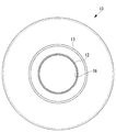
- the superconducting acceleration system is a device for giving kinetic energy to charged particles, and comprises a hollow tubular superconducting acceleration cavity 20 as shown in FIG.
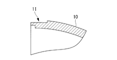
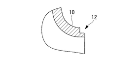
- the superconducting acceleration cavity 20 has a shape in which a large diameter portion 11 (equatorial portion) and a small diameter portion 12 (iris portion) are alternately repeated in the longitudinal direction, and a plurality of half cells 10 shown in FIGS. 2 and 3 are combined. It is formed.
- the half cell 10 is formed by pressing a pure niobium material plate.
- the half cell 10 has the large diameter portion 11 at one end 10 a and the small diameter portion 12 at the other end 10 b.
- An opening 17 is formed in the large diameter portion 11, and an opening 18 is formed in the small diameter portion 12.
- a middle portion between the large diameter portion 11 and the small diameter portion 12 has a curved surface shape, and a reinforcement wheel fixing portion 13 is provided at the middle portion.
- the two half cells 10 adjacent to each other are welded together to form the superconducting accelerated cavity 20 by welding the large diameter portions 11 with each other or the small diameter portions 12 with each other. Further, the reinforcing ring 21 is inserted between the two half cells 10, and the shape of the half cell 10 is maintained.
- the strengthening wheel 21 is welded to the strengthening wheel fixing portion 13.
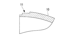
- the large diameter portion 11 and the small diameter portion 12 are formed with an inlay (fitting structure), and are fixed to the large diameter portion 11 and the small diameter portion 12 of the adjacent half cell 10 without moving in the radial direction.
- the large diameter portion 11 is a groove in which the tip of a protrusion provided from the large diameter portion 11 of one half cell 10 is provided in the large diameter portion 11 of the other half cell 10 as in the combination shown in FIGS. It is assembled by inserting in.
- the small diameter portion 12 is also assembled by the combination shown in FIGS. 5 and 8.
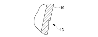
- the reinforcing ring fixing portion 13 has a step shape formed on the outer surface of the curved half-cell 10, and the reinforcing ring 21 is welded.
- the projections and grooves of the large diameter portion 11 and the small diameter portion 12 and the step shape of the strengthening wheel fixing portion 13 are formed by cutting with a cutting tool.
- the fixing jig 1 used for cutting of the half cell 10 will be described.
- the fixing jig 1 is fixed to the claw 3 of the lathe, and is rotated about an axis by a rotation driving unit (not shown).
- a workpiece 10A (object to be cut) to be a half cell 10 after processing is fixed to the fixing jig 1. Then, the cutting tool 4 cuts the rotating workpiece 10A.
- the fixing jig 1 is composed of a plurality of members, as shown in FIGS.
- the fixing jig 1 is Multiple members are combined in different patterns. Since the fixing jig 1 fixes the work 10A such that the portion to be cut is exposed, the work 10A can be reliably fixed while cutting the portion to be cut by appropriately combining a plurality of members. Since the combination of a plurality of members can be changed without removing the work 10A, a plurality of portions to be cut can be cut with respect to the work 10A at the same position, and the shape accuracy and the processing efficiency are improved.
- the fixing jig 1 includes a male die 31, a female die 32, a first large diameter side metal fitting 33, a second large diameter side metal fitting 34, a first small diameter side metal fitting 35, and a second small diameter side metal fitting 36. It comprises the third small diameter side metal fitting 37.
- the second large-diameter side metal fitting 34 is held by the claws 3 of the lathe, and the fixing jig 1 is fixed to the lathe.
- the second large diameter side fitting 34 is an axially long member.
- a male mold 31 is fixed to the end of the second large-diameter side fitting 34 opposite to the end of the second large-diameter end fitting held by the claws 3.
- the outer surface of the male mold 31 has a curved surface along the shape of the inner surface 15 of the workpiece 10A.
- the female mold 32 is fixed to the outer surface 16 of the work 10A.
- the work 10A is sandwiched between the male mold 31 and the female mold 32.
- the inner surface of the negative die 32 has a curved surface along the shape of the outer surface of the workpiece 10A.
- the surface of the male die 31 in contact with the work 10A is made of a material softer than pure niobium which is the material of the work 10A, such as MC nylon (registered trademark), pure aluminum, aluminum alloy or the like.
- the fixing method of the work 10A by the fixing jig 1 is based on the combination of the male mold 31 and the female mold 32. In the following, fixing and repairing in the case of processing each of the large diameter portion 11, the small diameter portion 12 and the strong ring fixing portion 13 The combination pattern of the tool 1 will be described.
- the 1st combination pattern in the case of processing the large diameter part 11 is demonstrated.
- the fixing jig 1 fixes the work 10A such that the large diameter portion 11 is exposed.
- a first small diameter metal fitting 35 is installed on the small diameter portion 12 side of the work 10A with respect to the female die 32 and on the outer surface 16 of the work 10A.
- a central portion of the first small-diameter-side metal fitting 35 is formed in a concave shape so that the small-diameter portion 12 of the work 10A is exposed.
- the third small diameter side metal fitting 37 is installed so as to cover the small diameter portion 12 so as to be in contact with the surface of the first small diameter metal fitting 35 opposite to the surface in contact with the female die 32.
- the first small diameter side fitting 35 and the third small diameter side fitting 37 are fixed to the male die 31 by the bolt 42, and the first small diameter side fitting 35 is fixed to the female die 32 by the bolt 43.
- the large diameter portion 11 is exposed while the work 10A is fixed to the fixing jig 1 by the first combination pattern, so that the large diameter portion 11 can be cut while the shape of the work 10A is maintained.
- the first small diameter side can be fixed so that the first small diameter side metal fitting 33 can be fixed to the work 10A side without removing the male mold 31 from the second large diameter side metal fitting 34
- the side fitting 33 is retracted to the claw 3 side of the lathe, and is fixed to the second large diameter side fitting 34 by the bolt 41.
- the fixing jig 1 fixes the work 10A so that the small diameter portion 12 is exposed.
- the first large diameter side metal fitting 33 is installed on the large diameter portion 11 side of the work 10A more than the male die 31 so as to cover the large diameter portion 11.
- the first large diameter side fitting 33 is fixed to the male die 31 by a bolt 44.
- the female die 32 is fixed to the first large-diameter side fitting 33 by the bolt 46 while maintaining the position of the first combination pattern.
- the third small diameter side metal fitting 37 in the first combination pattern is removed from the male die 31.
- the small diameter part 12 is exposed from between the male die 31 and the first small diameter side metal fitting 35, and the small diameter part 12 can be processed.
- the small diameter portion 12 is exposed while the work 10A is fixed to the fixing jig 1 by the second combination pattern, so that the small diameter portion 12 can be cut while the shape of the work 10A is maintained.
- the fixing jig 1 fixes the work 10A such that the reinforcing wheel fixing portion 13 is exposed.
- the first small diameter side metal fitting 35 in the second combination pattern is removed from the female die 32.
- the female die 32 is fixed to the first large diameter side fitting 33 by the bolt 46 while maintaining the position of the second combination pattern.
- the first large diameter side metal fitting 33 is fixed to the male die 31 by the bolt 44 while maintaining the position of the second combination pattern.
- the second small diameter side metal fitting 36 is installed on the small diameter portion 12 side so as to cover the small diameter portion 12.
- the second small diameter side metal fitting 36 is provided apart from the female die 32 so as to expose the reinforcing ring fixing portion 13, and is fixed to the male die 31 by a bolt 45.
- the reinforcement wheel fixing portion 13 can be cut while the shape of the workpiece 10A is maintained.
- the work 10A in the case of processing the work 10A, when there are a plurality of cut portions such as the large diameter portion 11, the small diameter portion 12 and the reinforcement wheel fixing portion 13, the work 10A is cut every cut portion It is possible to cut a plurality of cut parts while fixing the work 10A, without removing and re-fixing the work 10A. As a result, the processing efficiency can be enhanced while improving the shape accuracy when forming the superconducting acceleration cavity 10 from the workpiece 10A.
- the combination pattern is described to be shifted in the order of the first, second, and third combination patterns, but the present invention is not limited to this example. As long as the male mold 31 and the female mold 32 keep the work 10A fixed, the order of transfer of the combination pattern is arbitrary.
- FIG. 12 is a cross-sectional view taken along the line AA of FIG.
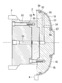
- the fixing jig 2 fixes the work 10A only from the inner surface 15 side of the work 10A, and metal fittings and the like for fixing the work 10A are installed on the outer surface 16 of the work 10A. There is nothing to do. Therefore, the large diameter portion 11, the small diameter portion 12, and the strong wheel fixing portion 13 which are to be cut are always exposed at the time of processing.
- the fixing jig 2 is composed of a plurality of members, such as a first member 51, a second member 52, and a third member 53, for example.
- the respective members are fixed to each other by bolts.
- a suction passage 56 for suctioning air from the work 10A side and discharging the air to the outside is provided inside each member.
- the outer surface of the first member 51 has a curved surface along the inner surface 15 of the workpiece 10A.
- the outer surface of the first member 51 in contact with the work 10A is made of a material softer than pure niobium which is the material of the work 10A, such as MC nylon (registered trademark), pure aluminum, aluminum alloy or the like.
- the outer surface of the first member 51 is formed with an opening 54 and an opening 55 connected to the suction passage 56.
- O-ring grooves 57 and 59 directly connected to the openings 54 and 55 are formed on the outer surface of the first member 51.
- the opening 54 is provided on the small diameter portion 12 side of the work 10A, and the O-ring groove 57 is formed on the small diameter portion 12 side of the opening 54.
- the opening 55 is provided on the large diameter portion 11 side of the work 10 A, and the O-ring groove 58 is formed on the large diameter portion 11 side of the opening 55. It is desirable that the positions at which the O-ring grooves 57, 59 are provided be as close as possible to the end portions 10a, 10b of the work 10A. As a result, the distance from the O-rings 58, 60 to the end portions 10a, 10b of the work 10A in a cantilever state becomes short, and generation of processing error due to vibration at the time of cutting can be suppressed.
- O-ring grooves 57, 59 be formed in the vicinity of the openings 54, 55. Thereby, the O-rings 58, 60 in the O-ring grooves 57, 59 are deformed before the air in the space between the workpiece 10A and the first member 51 is sucked. As a result, a closed space is reliably formed between the workpiece 10A and the first member 51, and a negative pressure can be easily generated between the workpiece 10A and the first member 51.
- connection destination of the suction path 56 is a vacuum unit (for example, a vacuum chuck unit MarkIII of Fuji Engineering, etc.), and the vacuum unit applies a negative pressure between the workpiece 10A and the first member 51 to make the workpiece 10A a first member. Fix it to 51.
- a vacuum unit for example, a vacuum chuck unit MarkIII of Fuji Engineering, etc.
- the vacuum unit When processing the workpiece 10A using the fixing jig 2, the vacuum unit is driven to suck the air existing between the workpiece 10A and the first member 51, and between the workpiece 10A and the first member 51 Apply negative pressure. Thereby, the work 10A is fixed to the first member 51. Then, the fixing jig 2 is rotated by the rotation drive unit to rotate the workpiece 10A around the axis. By using the cutting tool 4 with respect to the rotating workpiece 10A, the workpiece 10A is processed to form a half cell 10.
- the workpiece 10A and the first member 51 are in close contact with each other by vacuum suction, displacement of the workpiece 10A during processing can be prevented.
- the large diameter portion 11, the small diameter portion 12 and the reinforcing ring fixing portion 13 which are to be cut are always exposed at the time of processing, and therefore all cut portions can be cut without step replacement. Therefore, the processing efficiency can be enhanced while improving the shape accuracy when forming the half cell 10 from the workpiece 10A.
Landscapes
- Engineering & Computer Science (AREA)
- Mechanical Engineering (AREA)
- Physics & Mathematics (AREA)
- Plasma & Fusion (AREA)
- Spectroscopy & Molecular Physics (AREA)
- Milling Processes (AREA)
- Particle Accelerators (AREA)
- Jigs For Machine Tools (AREA)
- Turning (AREA)
Abstract
被切削対象を容易に加工することができ、精度の高い超伝導加速空洞を形成することが可能な加工装置及び加工方法を提供することを目的とする。加工装置は、一端側が大径部(11)であり、他端側が小径部(12)である中空状のワーク(10A)を加工して、ハーフセル(10)を形成する加工装置であって、ワーク(10A)を固定する固定治具(1)と、固定治具(1)を回転させる回転駆動部と、ワーク(10A)を切削する切削工具(4)とを備え、固定治具(1)は、複数の部材からなり、ワーク(10A)において第1の被切削部分を切削するとき、複数の部材は、第1の被切削部分が露出するように第1のパターンで組み合わされ、ワーク(10A)において第2の被切削部分を切削するとき、複数の部材は、第2の被切削部分が露出するように第2のパターンで組み合わされ、ワーク(10A)を取り外さずに、第1のパターンから第2のパターンへ複数の部材の組み合わせが変更される。
Description
本発明は、被切削対象を加工して超伝導加速空洞部材を形成する加工装置及び加工方法に関するものである。
超伝導加速システムは、荷電粒子に運動エネルギーを与える装置であり、中空状の超伝導加速空洞を備える。超伝導加速空洞は、大径部と小径部が長手方向に交互に繰り返された形状であり、純ニオブ製の素材板をプレス成形かつ切削加工した後にそれらを溶接して形成される。
特許文献1及び2では、空洞本体1を形成するため、一端が大径であり他端が小径である半割りセル11が複数個長手方向に連結される。特許文献3では、超伝導空洞1を形成するため、中央部の周りを凹ませたダンベル形状のダンベルセルと、椀形状のハーフセルが組み合わされて、長手方向に連結される。
超伝導加速空洞を形成するため、加速空洞部品であるハーフセル(半割り部材)の大径部、小径部、及び大径部と小径部の中間部に切削加工が施される。ところで、超伝導加速空洞は、使用時の性能を確保するため、高精度の組立てが要求される。そのため、ハーフセルの両端面の平行度が、例えば0.1mm以下に抑えられることが求められる場合がある。また、ハーフセルは、純ニオブ製であるため、高延性で柔らかい。更に、ハーフセルは、プレス成形品であることから、形状精度にばらつきがある。
したがって、被切削部分が複数個所あって、ハーフセルの被切削部分を変更する場合、一の被切削部分の切削が完了したのち、他の被切削部分の切削を開始する前に、被切削対象の位置ずれが生じないことが望ましい。
特許文献3では、ダンベル形状のダンベルセルを形成するために、金型を使用して円筒状の部材の中央部分を凹ませる。しかし、凹状の中央部分では、切削加工などの機械加工が困難であり、精度の高い超伝導加速空洞を形成することができなかった。
本発明は、このような事情に鑑みてなされたものであって、被切削対象を容易に加工することができ、精度の高い超伝導加速空洞を形成することが可能な加工装置及び加工方法を提供することを目的とする。
上記課題を解決するために、本発明の加工装置及び加工方法は以下の手段を採用する。
すなわち、本発明の一態様に係る加工装置は、一端側が大径部であり、他端側が小径部である中空状の被切削対象を加工して、加速空洞部材を形成する加工装置であって、被切削対象を固定する固定治具と、固定治具を回転させる回転駆動部と、被切削対象を切削する切削工具とを備え、固定治具は、複数の部材からなり、被切削対象において第1の被切削部分を切削するとき、複数の部材は、第1の被切削部分が露出するように第1のパターンで組み合わされ、被切削対象において第2の被切削部分を切削するとき、複数の部材は、第2の被切削部分が露出するように第1のパターンと異なる第2のパターンで組み合わされ、被切削対象を取り外さずに、第1のパターンから第2のパターンへ複数の部材の組み合わせが変更される。
すなわち、本発明の一態様に係る加工装置は、一端側が大径部であり、他端側が小径部である中空状の被切削対象を加工して、加速空洞部材を形成する加工装置であって、被切削対象を固定する固定治具と、固定治具を回転させる回転駆動部と、被切削対象を切削する切削工具とを備え、固定治具は、複数の部材からなり、被切削対象において第1の被切削部分を切削するとき、複数の部材は、第1の被切削部分が露出するように第1のパターンで組み合わされ、被切削対象において第2の被切削部分を切削するとき、複数の部材は、第2の被切削部分が露出するように第1のパターンと異なる第2のパターンで組み合わされ、被切削対象を取り外さずに、第1のパターンから第2のパターンへ複数の部材の組み合わせが変更される。
上記態様によれば、被切削対象が固定治具によって固定され、回転駆動部によって固定治具に固定された被切削対象が回転する。回転する被切削対象に対して切削工具を用いることによって、被切削対象が加工されて加速空洞部材が形成される。このとき、複数の被切削部分が存在する被切削対象を加工する際、被切削部分に応じて、固定治具の複数の部材が異なるパターンで組み合わされる。被切削部分が露出するように固定治具が被切削対象を固定することから、複数の部材を適切に組み合わせることによって、被切削部分を切削しつつ、被切削対象を確実に固定できる。被切削対象を取り外さずに複数の部材の組み合わせを変更できるため、被切削対象の位置を変更せずに複数の被切削部分を切削でき、形状精度と加工効率を向上させることができる。
本発明の一態様に係る加工装置は、一端側が大径部であり、他端側が小径部である中空状の被切削対象を加工して、加速空洞部の半割り部材を形成する加工装置であって、被切削対象の被切削部分が露出するように、被切削対象の内面を吸引して被切削対象を固定する固定治具と、固定治具を回転させる回転駆動部と、被切削対象を切削する切削工具とを備える。
上記態様によれば、被切削対象が内面を吸引されて固定治具に固定され、回転駆動部によって固定治具に固定された被切削対象が回転する。被切削部分が露出していることから、回転する被切削対象に対して切削工具を用いることによって、被切削対象が加工されて加速空洞部材が形成される。被切削対象は、内面側で支持されていることから、被切削対象を取り外さずに、被切削対象の位置を固定したまま複数の被切削部分を切削でき、形状精度と加工効率を向上させることができる。
本発明の一態様に係る加工方法は、一端側が大径部であり、他端側が小径部である中空状の被切削対象を加工して、加速空洞部材を形成する加工装置を用いた加工方法であって、複数の部材からなる固定治具が、被切削対象を固定するステップと、回転駆動部が、固定治具を回転させるステップと、切削工具が、被切削対象を切削するステップとを備え、被切削対象を固定するステップは、被切削対象において第1の被切削部分を切削するとき、複数の部材を、第1の被切削部分が露出するように第1のパターンで組み合わせるステップと、被切削対象において第2の被切削部分を切削するとき、複数の部材を、第2の被切削部分が露出するように第1のパターンと異なる第2のパターンで組み合わせるステップとを有し、被切削対象を取り外さずに、第1のパターンから第2のパターンへ複数の部材の組み合わせが変更される。
本発明の一態様に係る加工方法は、一端側が大径部であり、他端側が小径部である中空状の被切削対象を加工して、加速空洞部の半割り部材を形成する加工装置を用いた加工方法であって、固定治具が、被切削対象の被切削部分が露出するように、被切削対象の内面を吸引して被切削対象を固定するステップと、回転駆動部が、固定治具を回転させるステップと、切削工具が、被切削対象を切削するステップとを備える。
上記態様によれば、被切削対象を容易に加工することができ、精度の高い超伝導加速空洞を形成することができる。
以下に、本発明に係る実施形態について、図面を参照して説明する。
[第1実施形態]
以下、本発明の第1実施形態について、説明する。
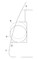
まず、超伝導加速システムに用いられる超伝導加速空洞20について説明する。超伝導加速システムは、荷電粒子に運動エネルギーを与える装置であり、図1に示すような中空管状の超伝導加速空洞20を備える。超伝導加速空洞20は、大径部11(赤道部)と小径部12(アイリス部)が長手方向に交互に繰り返された形状であり、図2及び図3に示すハーフセル10が複数組み合わされて形成される。
[第1実施形態]
以下、本発明の第1実施形態について、説明する。
まず、超伝導加速システムに用いられる超伝導加速空洞20について説明する。超伝導加速システムは、荷電粒子に運動エネルギーを与える装置であり、図1に示すような中空管状の超伝導加速空洞20を備える。超伝導加速空洞20は、大径部11(赤道部)と小径部12(アイリス部)が長手方向に交互に繰り返された形状であり、図2及び図3に示すハーフセル10が複数組み合わされて形成される。
ハーフセル10は、純ニオブ製の素材板をプレス成形して形成される。ハーフセル10は、一端10aに大径部11を有し、他端10bに小径部12を有する。大径部11には、開口17が形成され、小径部12には、開口18が形成される。大径部11と小径部12の中間は、曲面形状を有し、中間部分に強め輪固定部13を有する。
互いに隣接する二つのハーフセル10は、大径部11同士又は小径部12同士が溶接されて、超伝導加速空洞20を形成する。また、二つのハーフセル10間には、強め輪21が挿入されて、ハーフセル10の形状が維持される。強め輪21は、強め輪固定部13に溶接される。大径部11及び小径部12は、インロー(嵌め合い構造)が形成されて、隣接するハーフセル10の大径部11及び小径部12に対して半径方向へ移動すること無く固定される。
例えば、大径部11は、図4及び図7に示す組み合わせのように、一方のハーフセル10の大径部11から設けた突起の先端を、他方のハーフセル10の大径部11に設けた溝に挿入することで組み立てられる。小径部12についても、図5及び図8に示す組み合わせにより、組み立てられる。
強め輪固定部13は、図6に示すように、曲面形状のハーフセル10の外面に形成された段差形状を有し、強め輪21が溶接される。
大径部11及び小径部12の突起や溝、強め輪固定部13の段差形状等は、切削工具による切削加工によって、形成される。以下、ハーフセル10の切削加工に用いる固定治具1について説明する。
固定治具1は、図9に示すように、旋盤の爪3に固定されて、回転駆動部(図示せず。)によって軸線周りに回転する。固定治具1には、加工後にハーフセル10となるワーク10A(被切削対象)が固定される。そして、切削工具4が、回転するワーク10Aを切削する。
固定治具1は、図9~図11に示すように、複数の部材から構成される。上述したハーフセル10のように、大径部11、小径部12及び強め輪固定部13といった複数の被切削部分が存在するワーク10Aを加工する場合、被切削部分に応じて、固定治具1の複数の部材が異なるパターンで組み合わされる。被切削部分が露出するように固定治具1がワーク10Aを固定することから、複数の部材を適切に組み合わせることによって、被切削部分を切削しつつ、ワーク10Aを確実に固定できる。ワーク10Aを取り外さずに複数の部材の組み合わせを変更できるため、同一位置のワーク10Aに対して複数の被切削部分を切削でき、形状精度と加工効率が向上する。
固定治具1は、雄型31と、雌型32と、第1大径側金具33と、第2大径側金具34と、第1小径側金具35と、第2小径側金具36と、第3小径側金具37から構成される。
図9に示すように、第2大径側金具34が旋盤の爪3によって挟持され、固定治具1が旋盤に対して固定される。第2大径側金具34は、軸方向に長い部材である。第2大径側金具34のうち爪3に挟持される端部側に対して反対側の端部には、雄型31が固定される。雄型31の外表面は、ワーク10Aの内面15の形状に沿った曲面を有する。雄型31の外表面にワーク10Aが設置されると、ワーク10Aの外面16に雌型32が固定される。ワーク10Aは、雄型31と雌型32によって挟み込まれる。雌型32の内表面は、ワーク10Aの外面の形状に沿った曲面を有する。
雄型31のワーク10Aと接触する面は、ワーク10Aの素材である純ニオブよりも柔らかい材料、例えばMCナイロン(登録商標)、純アルミニウム、アルミニウム合金等が用いられる。これにより、固定治具1にワーク10Aが固定されたときに、ワーク10Aの内面15が傷つくことを防止できる。
固定治具1によるワーク10Aの固定方法は、上記雄型31と雌型32の組み合わせを基本とし、以下、大径部11、小径部12、強め輪固定部13それぞれを加工する場合の固定治具1の組み合わせパターンについて説明する。
まず、図9を参照して、大径部11を加工する場合の第1組み合わせパターンについて説明する。大径部11を加工する場合、固定治具1は、大径部11が露出するようにワーク10Aを固定する。
雌型32よりもワーク10Aの小径部12側かつワーク10Aの外面16に、第1小径側金具35が設置される。第1小径側金具35は、ワーク10Aの小径部12が露出するように中央部分が凹状に形成されている。また、第3小径側金具37が、小径部12を覆うように、第1小径金具35のうち雌型32と接する側の面に対して反対側の面と接するように設置される。
ボルト42によって、第1小径側金具35と第3小径側金具37が雄型31に固定され、ボルト43によって第1小径側金具35が雌型32に固定される。
上記第1組み合わせパターンによって、ワーク10Aは、固定治具1に固定されつつ大径部11が露出するため、ワーク10Aの形状が維持されつつ、大径部11の切削が可能になる。この組み合わせパターンにおいて、次の組み合わせパターンへ移行するときに、雄型31を第2大径側金具34から取り外さないで、第1小径側金具33をワーク10A側へ固定できるように、第1小径側金具33は、旋盤の爪3側へ退避され、ボルト41によって第2大径側金具34に対して固定される。
次に、図11を参照して、小径部12を加工する場合の第2組み合わせパターンについて説明する。小径部12を加工する場合、固定治具1は、小径部12が露出するようにワーク10Aを固定する。
雄型31よりもワーク10Aの大径部11側に、第1大径側金具33が大径部11を覆うように設置される。第1大径側金具33は、ボルト44によって雄型31に対して固定される。そして、雌型32が、第1組み合わせパターンの位置を維持したまま、第1大径側金具33に対してボルト46によって固定される。
第1組み合わせパターンにおける第3小径側金具37は、雄型31から取り外される。第3小径側金具37が取り外されることによって、小径部12が雄型31と第1小径側金具35の間から露出し、小径部12の加工が可能になる。
上記第2組み合わせパターンによって、ワーク10Aは、固定治具1に固定されつつ小径部12が露出するため、ワーク10Aの形状が維持されつつ、小径部12の切削が可能になる。
次に、図10を参照して、強め輪固定部13を加工する場合の第3組み合わせパターンについて説明する。強め輪固定部13を加工する場合、固定治具1は、強め輪固定部13が露出するようにワーク10Aを固定する。
上記第2組み合わせパターンにおける第1小径側金具35が、雌型32から取り外される。このとき、雌型32が、第2組み合わせパターンの位置を維持したまま、第1大径側金具33に対してボルト46によって固定される。第1大径側金具33は、第2組み合わせパターンの位置を維持したまま、雄型31に対してボルト44によって固定される。
第3組み合わせパターンでは、第2小径側金具36が小径部12を覆うように小径部12側に設置される。第2小径側金具36は、強め輪固定部13が露出するように、雌型32から離隔して設けられ、ボルト45によって雄型31に対して固定される。
上記第3組み合わせパターンによって、ワーク10Aは、固定治具1に固定されつつ強め輪固定部13が露出するため、ワーク10Aの形状が維持されつつ、強め輪固定部13の切削が可能になる。
以上、本実施形態によれば、ワーク10Aを加工する場合において、大径部11、小径部12、強め輪固定部13のように複数の被切削部分がある場合、ワーク10Aを被切削部分ごとに取り外したり再度固定したりと段取り替えすることなく、ワーク10Aを固定したまま複数の被切削部分を切削できる。その結果、ワーク10Aから超伝導加速空洞10を形成する際の形状精度を向上させつつ、加工能率を高めることができる。
上記第1実施形態において、組み合わせパターンは、第1、第2、第3組み合わせパターンの順で移行する場合について説明したが、本発明はこの例に限定されない。雄型31及び雌型32がワーク10Aを固定維持したままであれば、組み合わせパターンの移行の順番は任意である。
[第2実施形態]
次に、本発明の第2実施形態に係る固定治具2について説明する。
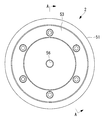
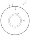
固定治具2は、図12に示すように、旋盤の爪3に固定されて、回転駆動部(図示せず。)によって軸線周りに回転する。固定治具2には、加工後にハーフセル10となるワーク10A(被切削対象)が吸引固定される。そして、切削工具4が、回転するワーク10Aを切削する。図13は、本実施形態に係る固定治具を示す背面図であり、図14は、本実施形態に係る固定治具を示す正面図である。図12は、図13のA-A線で切断した断面図である。
次に、本発明の第2実施形態に係る固定治具2について説明する。
固定治具2は、図12に示すように、旋盤の爪3に固定されて、回転駆動部(図示せず。)によって軸線周りに回転する。固定治具2には、加工後にハーフセル10となるワーク10A(被切削対象)が吸引固定される。そして、切削工具4が、回転するワーク10Aを切削する。図13は、本実施形態に係る固定治具を示す背面図であり、図14は、本実施形態に係る固定治具を示す正面図である。図12は、図13のA-A線で切断した断面図である。
固定治具2は、第1実施形態の固定治具1と異なり、ワーク10Aの内面15側からのみワーク10Aを固定し、ワーク10Aの外面16にはワーク10Aを固定する金具等が設置されることはない。そのため、被切削部分である大径部11、小径部12及び強め輪固定部13は、加工時に常時露出している。
固定治具2は、例えば第1部材51と、第2部材52と、第3部材53のように複数の部材から構成される。それぞれの部材は互いにボルトによって固定される。各部材の内部には、ワーク10A側から空気を吸引して外部へ空気を排出するための吸引路56が設けられる。
第1部材51の外表面は、ワーク10Aの内面15に沿った曲面を有する。第1部材51のワーク10Aと接触する外表面は、ワーク10Aの素材である純ニオブよりも柔らかい材料、例えばMCナイロン(登録商標)、純アルミニウム、アルミニウム合金等が用いられる。これにより、固定治具2がワーク10Aを吸着固定したときに、ワーク10Aの内面15が傷つくことを防止できる。
第1部材51の外表面は、吸引路56と接続された開口部54及び開口部55が形成される。図12及び図14に示すように、開口部54、55それぞれに直結したOリング溝57、59が、第1部材51の外表面に形成される。開口部54、55とOリング溝57、59が接続されることによって、Oリング溝57、59内の空気が吸引されて、外部へ排出される。Oリング溝57、59内には、Oリング58、60が設置される。図15は、Oリング溝59内にOリング60を設置する場合の一例を示している。
開口部54は、ワーク10Aの小径部12側に設けられ、Oリング溝57は、開口部54よりも小径部12側に形成される。開口部55は、ワーク10Aの大径部11側に設けられ、Oリング溝58は、開口部55よりも大径部11側に形成される。Oリング溝57、59が設けられる位置は、可能な限りワーク10Aの端部10a、10bに近いことが望ましい。これにより、Oリング58、60からワーク10Aの端部10a、10bまで片持ち状態になる距離が短くなり、切削加工時の振動による加工誤差の発生を抑制できる。
開口部54、55の近傍にOリング溝57、59が形成されることが望ましい。これにより、ワーク10Aと第1部材51との間の空間の空気が吸引される前に、Oリング溝57、59内のOリング58、60が変形する。その結果、ワーク10Aと第1部材51との間に閉空間が確実に形成され、ワーク10Aと第1部材51との間を負圧にしやすくすることができる。
吸引路56の接続先は、真空ユニット(例えばFuji Engineering社の真空チャックユニットMarkIIIなど)であり、真空ユニットは、ワーク10Aと第1部材51との間を負圧にし、ワーク10Aを第1部材51に対して固定する。
固定治具2を用いてワーク10Aを加工する場合、真空ユニットを駆動し、ワーク10Aと第1部材51との間に存在する空気を吸引して、ワーク10Aと第1部材51との間を負圧にする。これにより、ワーク10Aが第1部材51に対して固定される。そして、固定治具2を回転駆動部によって回転させて、ワーク10Aを軸線周りに回転させる。回転しているワーク10Aに対して切削工具4を用いることによって、ワーク10Aが加工されてハーフセル10が形成される。
真空吸着によって、ワーク10Aと第1部材51が密着することから、加工時にワーク10Aが位置ずれすることを防止できる。被切削部分である大径部11、小径部12及び強め輪固定部13は、加工時に常時露出していることから、段取り替えすることなく、全ての被切削部分を切削できる。したがって、ワーク10Aからハーフセル10を形成する際の形状精度を向上させつつ、加工能率を高めることができる。
1,2 固定治具
3 爪
4 切削工具
10 ハーフセル
10A ワーク
11 大径部
12 小径部
13 強め輪固定部
20 超伝導加速空洞
21 強め輪
31 雄型
32 雌型
33 第1大径側金具
34 第2大径側金具
35 第1小径側金具
36 第2小径側金具
37 第3小径側金具
51 第1部材
52 第2部材
53 第3部材
54,55 開口部
56 吸引路
57,59 Oリング溝
58,60 Oリング
3 爪
4 切削工具
10 ハーフセル
10A ワーク
11 大径部
12 小径部
13 強め輪固定部
20 超伝導加速空洞
21 強め輪
31 雄型
32 雌型
33 第1大径側金具
34 第2大径側金具
35 第1小径側金具
36 第2小径側金具
37 第3小径側金具
51 第1部材
52 第2部材
53 第3部材
54,55 開口部
56 吸引路
57,59 Oリング溝
58,60 Oリング
Claims (4)
- 一端側が大径部であり、他端側が小径部である中空状の被切削対象を加工して、加速空洞部材を形成する加工装置であって、
前記被切削対象を固定する固定治具と、
前記固定治具を回転させる回転駆動部と、
前記被切削対象を切削する切削工具と、
を備え、
前記固定治具は、複数の部材からなり、
前記被切削対象において第1の被切削部分を切削するとき、前記複数の部材は、前記第1の被切削部分が露出するように第1のパターンで組み合わされ、前記被切削対象において第2の被切削部分を切削するとき、前記複数の部材は、前記第2の被切削部分が露出するように前記第1のパターンと異なる第2のパターンで組み合わされ、
前記被切削対象を取り外さずに、前記第1のパターンから前記第2のパターンへ前記複数の部材の組み合わせが変更される加工装置。 - 一端側が大径部であり、他端側が小径部である中空状の被切削対象を加工して、加速空洞部の半割り部材を形成する加工装置であって、
前記被切削対象の被切削部分が露出するように、前記被切削対象の内面を吸引して前記被切削対象を固定する固定治具と、
前記固定治具を回転させる回転駆動部と、
前記被切削対象を切削する切削工具と、
を備える加工装置。 - 一端側が大径部であり、他端側が小径部である中空状の被切削対象を加工して、加速空洞部材を形成する加工装置を用いた加工方法であって、
複数の部材からなる固定治具が、前記被切削対象を固定するステップと、
回転駆動部が、前記固定治具を回転させるステップと、
切削工具が、前記被切削対象を切削するステップと、
を備え、
前記被切削対象を固定するステップは、
前記被切削対象において第1の被切削部分を切削するとき、前記複数の部材を、前記第1の被切削部分が露出するように第1のパターンで組み合わせるステップと、
前記被切削対象において第2の被切削部分を切削するとき、前記複数の部材を、前記第2の被切削部分が露出するように前記第1のパターンと異なる第2のパターンで組み合わせるステップと、
を有し、
前記被切削対象を取り外さずに、前記第1のパターンから前記第2のパターンへ前記複数の部材の組み合わせが変更される加工方法。 - 一端側が大径部であり、他端側が小径部である中空状の被切削対象を加工して、加速空洞部の半割り部材を形成する加工装置を用いた加工方法であって、
固定治具が、前記被切削対象の被切削部分が露出するように、前記被切削対象の内面を吸引して前記被切削対象を固定するステップと、
回転駆動部が、前記固定治具を回転させるステップと、
切削工具が、前記被切削対象を切削するステップと、
を備える加工方法。
Priority Applications (2)
| Application Number | Priority Date | Filing Date | Title |
|---|---|---|---|
| US14/127,828 US10035229B2 (en) | 2011-08-11 | 2012-08-07 | Processing apparatus and processing method |
| EP12822311.2A EP2744308B8 (en) | 2011-08-11 | 2012-08-07 | Processing apparatus and processing method |
Applications Claiming Priority (2)
| Application Number | Priority Date | Filing Date | Title |
|---|---|---|---|
| JP2011175939A JP5804840B2 (ja) | 2011-08-11 | 2011-08-11 | 加工装置及び加工方法 |
| JP2011-175939 | 2011-08-11 |
Publications (1)
| Publication Number | Publication Date |
|---|---|
| WO2013021999A1 true WO2013021999A1 (ja) | 2013-02-14 |
Family
ID=47668506
Family Applications (1)
| Application Number | Title | Priority Date | Filing Date |
|---|---|---|---|
| PCT/JP2012/070102 Ceased WO2013021999A1 (ja) | 2011-08-11 | 2012-08-07 | 加工装置及び加工方法 |
Country Status (4)
| Country | Link |
|---|---|
| US (1) | US10035229B2 (ja) |
| EP (1) | EP2744308B8 (ja) |
| JP (1) | JP5804840B2 (ja) |
| WO (1) | WO2013021999A1 (ja) |
Cited By (2)
| Publication number | Priority date | Publication date | Assignee | Title |
|---|---|---|---|---|
| CN103624680A (zh) * | 2013-11-19 | 2014-03-12 | 西安航天动力机械厂 | 一种用于少半球球体展成磨削的装夹装置 |
| CN111571311A (zh) * | 2020-05-06 | 2020-08-25 | 扬州恒达数控机床有限公司 | 一种高效环保型数控加工中心 |
Families Citing this family (4)
| Publication number | Priority date | Publication date | Assignee | Title |
|---|---|---|---|---|
| JP5985011B1 (ja) * | 2015-06-30 | 2016-09-06 | 三菱重工メカトロシステムズ株式会社 | 超伝導加速器 |
| CN108655772B (zh) * | 2018-03-27 | 2020-09-15 | 武汉船用机械有限责任公司 | 燃气轮机整流罩壳的车削夹具 |
| CN109128904B (zh) * | 2018-09-13 | 2020-02-07 | 杭州富阳富宝仪表机床厂 | 一种薄壁机匣类零件精密孔加工设备 |
| JP7610194B2 (ja) | 2020-03-26 | 2025-01-08 | 株式会社ミラプロ | 加工装置および加工方法 |
Citations (12)
| Publication number | Priority date | Publication date | Assignee | Title |
|---|---|---|---|---|
| JPH03117548A (ja) * | 1989-09-29 | 1991-05-20 | Olympus Optical Co Ltd | 研摩用ワークホルダー |
| JPH08216013A (ja) * | 1995-02-14 | 1996-08-27 | Shinei Kiko Kk | 陶磁器の表面研磨方法及びその研磨装置 |
| JPH09180899A (ja) * | 1995-12-27 | 1997-07-11 | Shuichi Noguchi | 超伝導加速空洞の芯出し装置 |
| JPH1148002A (ja) * | 1997-07-31 | 1999-02-23 | Menicon Co Ltd | 眼用レンズの製造方法および眼用レンズの切削加工用保持具 |
| JP2000348900A (ja) * | 1999-06-07 | 2000-12-15 | Toshiba Corp | 超電導高周波加速空胴の製造方法 |
| JP2003036999A (ja) | 2001-07-19 | 2003-02-07 | Toshiba Corp | 超電導高周波加速空胴の製造方法 |
| JP2003037000A (ja) | 2001-07-19 | 2003-02-07 | Toshiba Corp | 超電導高周波加速空胴の製造方法 |
| JP2006318890A (ja) | 2005-04-12 | 2006-11-24 | Mitsubishi Heavy Ind Ltd | 超伝導加速空洞の製造方法 |
| WO2010016337A1 (ja) * | 2008-08-07 | 2010-02-11 | 大学共同利用機関法人高エネルギー加速器研究機構 | 超伝導高周波加速空洞の製造方法 |
| JP2011167709A (ja) * | 2010-02-17 | 2011-09-01 | Mitsubishi Heavy Ind Ltd | 溶接方法および超伝導加速器 |
| WO2011142348A1 (ja) * | 2010-05-12 | 2011-11-17 | 三菱重工業株式会社 | 超伝導加速空洞および超伝導加速空洞の製造方法 |
| JP2011238517A (ja) * | 2010-05-12 | 2011-11-24 | Mitsubishi Heavy Ind Ltd | 超伝導加速空洞の製造方法 |
Family Cites Families (12)
| Publication number | Priority date | Publication date | Assignee | Title |
|---|---|---|---|---|
| US2681806A (en) * | 1949-11-23 | 1954-06-22 | Barrus Walter Elvin | Valve gate turning jig |
| US2887833A (en) * | 1958-04-03 | 1959-05-26 | Passarotti Anthony | Tool grinding jig |
| US5291692A (en) | 1989-09-14 | 1994-03-08 | Olympus Optical Company Limited | Polishing work holder |
| US5239157A (en) * | 1990-10-31 | 1993-08-24 | The Furukawa Electric Co., Ltd. | Superconducting accelerating tube and a method for manufacturing the same |
| ATE153211T1 (de) * | 1993-06-14 | 1997-05-15 | Ist Nazionale Fisica Nucleare | Herstellungsverfahren von nahtloser radiofrequenz-resonanzholräumen und dadurch erhaltenes produkt |
| JPH0966401A (ja) * | 1995-06-21 | 1997-03-11 | Canon Inc | 円筒部材およびその製造方法ならびに製造装置 |
| JP3959198B2 (ja) * | 1999-03-09 | 2007-08-15 | 株式会社東芝 | 超電導キャビティ、その製造方法、及び超電導加速器 |
| US6758640B2 (en) * | 2000-10-11 | 2004-07-06 | Fuji Seiko Limited | Method and apparatus for controlling movement of cutting blade and workpiece |
| JP2005001100A (ja) * | 2003-02-21 | 2005-01-06 | Seiko Epson Corp | 非球面加工方法及び非球面形成方法 |
| DE102006021111B3 (de) * | 2005-12-02 | 2007-08-02 | Deutsches Elektronen-Synchrotron Desy | Verfahren zur Herstellung von Hohlkörpern von Resonatoren |
| JP4890424B2 (ja) | 2007-11-13 | 2012-03-07 | 川崎重工業株式会社 | 薄板曲面被加工物の加工装置 |
| WO2011055373A1 (en) * | 2009-11-03 | 2011-05-12 | The Secretary, Department Of Atomic Energy,Govt.Of India. | Niobium based superconducting radio frequency (scrf) cavities comprising niobium components joined by laser welding; method and apparatus for manufacturing such cavities |
-
2011
- 2011-08-11 JP JP2011175939A patent/JP5804840B2/ja not_active Expired - Fee Related
-
2012
- 2012-08-07 US US14/127,828 patent/US10035229B2/en active Active
- 2012-08-07 EP EP12822311.2A patent/EP2744308B8/en active Active
- 2012-08-07 WO PCT/JP2012/070102 patent/WO2013021999A1/ja not_active Ceased
Patent Citations (12)
| Publication number | Priority date | Publication date | Assignee | Title |
|---|---|---|---|---|
| JPH03117548A (ja) * | 1989-09-29 | 1991-05-20 | Olympus Optical Co Ltd | 研摩用ワークホルダー |
| JPH08216013A (ja) * | 1995-02-14 | 1996-08-27 | Shinei Kiko Kk | 陶磁器の表面研磨方法及びその研磨装置 |
| JPH09180899A (ja) * | 1995-12-27 | 1997-07-11 | Shuichi Noguchi | 超伝導加速空洞の芯出し装置 |
| JPH1148002A (ja) * | 1997-07-31 | 1999-02-23 | Menicon Co Ltd | 眼用レンズの製造方法および眼用レンズの切削加工用保持具 |
| JP2000348900A (ja) * | 1999-06-07 | 2000-12-15 | Toshiba Corp | 超電導高周波加速空胴の製造方法 |
| JP2003036999A (ja) | 2001-07-19 | 2003-02-07 | Toshiba Corp | 超電導高周波加速空胴の製造方法 |
| JP2003037000A (ja) | 2001-07-19 | 2003-02-07 | Toshiba Corp | 超電導高周波加速空胴の製造方法 |
| JP2006318890A (ja) | 2005-04-12 | 2006-11-24 | Mitsubishi Heavy Ind Ltd | 超伝導加速空洞の製造方法 |
| WO2010016337A1 (ja) * | 2008-08-07 | 2010-02-11 | 大学共同利用機関法人高エネルギー加速器研究機構 | 超伝導高周波加速空洞の製造方法 |
| JP2011167709A (ja) * | 2010-02-17 | 2011-09-01 | Mitsubishi Heavy Ind Ltd | 溶接方法および超伝導加速器 |
| WO2011142348A1 (ja) * | 2010-05-12 | 2011-11-17 | 三菱重工業株式会社 | 超伝導加速空洞および超伝導加速空洞の製造方法 |
| JP2011238517A (ja) * | 2010-05-12 | 2011-11-24 | Mitsubishi Heavy Ind Ltd | 超伝導加速空洞の製造方法 |
Non-Patent Citations (1)
| Title |
|---|
| TAMAO HIGUCHI: "Atarashii Kikai Kenma to Denkai Kenma ni yoru Suiso Kuzo o Okosanai Chodendo Kudo no Hyomen Shoriho no Kaihatsu", ILC-TAMAWO HIGUCHI'S PHD THESIS, 3 March 2006 (2006-03-03), XP008172670, Retrieved from the Internet <URL:http://ilc-dms.fnal.gov/Members/tajima/References/foldercontents> [retrieved on 20121106] * |
Cited By (3)
| Publication number | Priority date | Publication date | Assignee | Title |
|---|---|---|---|---|
| CN103624680A (zh) * | 2013-11-19 | 2014-03-12 | 西安航天动力机械厂 | 一种用于少半球球体展成磨削的装夹装置 |
| CN103624680B (zh) * | 2013-11-19 | 2016-01-20 | 西安航天动力机械厂 | 一种用于少半球球体展成磨削的装夹装置 |
| CN111571311A (zh) * | 2020-05-06 | 2020-08-25 | 扬州恒达数控机床有限公司 | 一种高效环保型数控加工中心 |
Also Published As
| Publication number | Publication date |
|---|---|
| JP2013041671A (ja) | 2013-02-28 |
| EP2744308B8 (en) | 2018-04-18 |
| JP5804840B2 (ja) | 2015-11-04 |
| US10035229B2 (en) | 2018-07-31 |
| EP2744308A1 (en) | 2014-06-18 |
| EP2744308A4 (en) | 2015-04-01 |
| EP2744308B1 (en) | 2018-03-14 |
| US20140137711A1 (en) | 2014-05-22 |
Similar Documents
| Publication | Publication Date | Title |
|---|---|---|
| JP5804840B2 (ja) | 加工装置及び加工方法 | |
| US8579559B2 (en) | Grooving work method and grooving work apparatus | |
| CN1390162A (zh) | 外科器械用的末端封闭的管件的制造 | |
| IL201986A (en) | A method of production that uses the same factual characteristics about different things that are in the processing stages | |
| KR20080019574A (ko) | 마이크로 스탬프의 표면 결함을 감소시키는 방법 및 장치 | |
| CN204545483U (zh) | 薄壁长筒体零件用加工工装 | |
| JP2007092968A (ja) | ナットの製造方法 | |
| JP5489830B2 (ja) | 外導体製造方法 | |
| US11213902B2 (en) | Broaching machine and lathe comprising same | |
| CN103212898B (zh) | 一种适用于薄壁管材的气动夹持系统 | |
| KR101057983B1 (ko) | 벨트 풀리 제조방법 | |
| KR20100026828A (ko) | 임펠러 제조방법 | |
| JP2002233908A (ja) | 管継手用管体加工装置 | |
| CN115610617B (zh) | 一种悬臂结构件的制造方法及悬臂结构件 | |
| CN116998090A (zh) | 用于电机的转子 | |
| JPH106111A (ja) | ワーク支持装置 | |
| CN110814194B (zh) | 一种管端成型机的多工位换向机构 | |
| JP2013208690A (ja) | チャック装置及び切削装置 | |
| CN202607103U (zh) | 一种适用于薄壁管材的气动夹持系统 | |
| CN121004287B (zh) | 一种球阀加工用切削装置 | |
| JP3240263U (ja) | 金属管加工装置 | |
| CN219684587U (zh) | 一种用于内壁带键槽筒形件的夹紧工装 | |
| US11904420B2 (en) | Method for manufacturing a turbomachine compressor blade by compacting | |
| KR102180103B1 (ko) | 언발란스 제품 가공방법 및 가공용 지그 | |
| CN108687447B (zh) | 一种切管机切口加工方法 |
Legal Events
| Date | Code | Title | Description |
|---|---|---|---|
| 121 | Ep: the epo has been informed by wipo that ep was designated in this application |
Ref document number: 12822311 Country of ref document: EP Kind code of ref document: A1 |
|
| WWE | Wipo information: entry into national phase |
Ref document number: 14127828 Country of ref document: US |
|
| NENP | Non-entry into the national phase |
Ref country code: DE |