WO2013027376A1 - 操作装置 - Google Patents
操作装置 Download PDFInfo
- Publication number
- WO2013027376A1 WO2013027376A1 PCT/JP2012/005172 JP2012005172W WO2013027376A1 WO 2013027376 A1 WO2013027376 A1 WO 2013027376A1 JP 2012005172 W JP2012005172 W JP 2012005172W WO 2013027376 A1 WO2013027376 A1 WO 2013027376A1
- Authority
- WO
- WIPO (PCT)
- Prior art keywords
- buttons
- button
- operation button
- operating
- board
- Prior art date
- Legal status (The legal status is an assumption and is not a legal conclusion. Google has not performed a legal analysis and makes no representation as to the accuracy of the status listed.)
- Ceased
Links
Images




Classifications
-
- H—ELECTRICITY
- H01—ELECTRIC ELEMENTS
- H01H—ELECTRIC SWITCHES; RELAYS; SELECTORS; EMERGENCY PROTECTIVE DEVICES
- H01H13/00—Switches having rectilinearly-movable operating part or parts adapted for pushing or pulling in one direction only, e.g. push-button switch
- H01H13/70—Switches having rectilinearly-movable operating part or parts adapted for pushing or pulling in one direction only, e.g. push-button switch having a plurality of operating members associated with different sets of contacts, e.g. keyboard
- H01H13/84—Switches having rectilinearly-movable operating part or parts adapted for pushing or pulling in one direction only, e.g. push-button switch having a plurality of operating members associated with different sets of contacts, e.g. keyboard characterised by ergonomic functions, e.g. for miniature keyboards; characterised by operational sensory functions, e.g. sound feedback
-
- H—ELECTRICITY
- H01—ELECTRIC ELEMENTS
- H01H—ELECTRIC SWITCHES; RELAYS; SELECTORS; EMERGENCY PROTECTIVE DEVICES
- H01H13/00—Switches having rectilinearly-movable operating part or parts adapted for pushing or pulling in one direction only, e.g. push-button switch
- H01H13/70—Switches having rectilinearly-movable operating part or parts adapted for pushing or pulling in one direction only, e.g. push-button switch having a plurality of operating members associated with different sets of contacts, e.g. keyboard
-
- H—ELECTRICITY
- H01—ELECTRIC ELEMENTS
- H01H—ELECTRIC SWITCHES; RELAYS; SELECTORS; EMERGENCY PROTECTIVE DEVICES
- H01H2211/00—Spacers
- H01H2211/006—Individual areas
-
- H—ELECTRICITY
- H01—ELECTRIC ELEMENTS
- H01H—ELECTRIC SWITCHES; RELAYS; SELECTORS; EMERGENCY PROTECTIVE DEVICES
- H01H2227/00—Dimensions; Characteristics
- H01H2227/024—Spacer elements
-
- H—ELECTRICITY
- H01—ELECTRIC ELEMENTS
- H01H—ELECTRIC SWITCHES; RELAYS; SELECTORS; EMERGENCY PROTECTIVE DEVICES
- H01H2227/00—Dimensions; Characteristics
- H01H2227/036—Minimise height
-
- H—ELECTRICITY
- H01—ELECTRIC ELEMENTS
- H01H—ELECTRIC SWITCHES; RELAYS; SELECTORS; EMERGENCY PROTECTIVE DEVICES
- H01H2233/00—Key modules
- H01H2233/002—Key modules joined to form button rows
- H01H2233/004—One molded part
Definitions
- the present invention relates to an operation device constituting an operation unit in an electronic device.
- buttons are generally known to have a configuration in which a plurality of buttons are located at separate locations or a configuration in which the buttons are arranged side by side and in parallel with no gap (see, for example, Patent Document 1). ).
- a button configuration in which a plurality of buttons are located at remote locations it is relatively easy to use a resin in which a plurality of buttons are integrally molded, which causes problems in appearance such as parallelism of buttons. It is possible to solve.
- FIG. 7 is an external perspective view showing a conventional operating device.
- the operation button 11 has a configuration independent of the operation unit 12.
- Each operation button 11 protrudes independently from the exterior surface through an opening for each button opened in the operation unit 12.
- An operation sheet 15 is attached to the front surface of the operation unit 12.
- FIG. 8 is a front view showing an example of operation buttons in the operation device of this configuration. As shown in FIG. 8, in a button layout in which a plurality of buttons are respectively located at a certain distance, it is relatively easy to solve the problem of configuring the operation buttons integrally.
- buttons 11 as shown in FIG. 7 are integrated, and there is a certain gap (generally about 1 mm) between the buttons. ) Will occur.
- it is generally used to make each button an independent component configuration.
- FIG. 9 is an external perspective view having a button layout in which a plurality of buttons are arranged side by side without gaps.
- the operation button 11 has a configuration in which a gap between adjacent operation buttons 11 is small.
- the operation buttons 11 a, 11 b, and 11 c are independently disposed on the operation unit 12.
- the operation board 14 is supported by the operation unit 12.
- the operation board 13 is provided with an operation switch 13 on the side facing the operation button 11.
- each operation button 11 makes each operation button 11 an independent component has problems in terms of cost and assembly man-hours such as an increase in the number of molded parts and an increase in assembly work. It was intervening. In order to solve this, it is necessary to mold each operation button 11 integrally. However, the problem that the gap between adjacent operation buttons 11 becomes large due to the molding problem due to the molding. I have.
- each operation button is integrally molded, that is, has a one-part configuration, and its adverse effect is adjacent.
- An object of the present invention is to provide an operating device that can reduce the number of parts and simplify assembly by reducing the gap between the buttons.
- an operation device includes an operation board for controlling an electronic device, an operation part for supporting the operation board, and two or more horizontally and integrally supported by the operation part.
- An operation button for performing the selected operation an operation switch mounted on the operation board and disposed on a surface facing the operation button, an opening for disposing the operation button of the operation unit, It is provided with a peripheral part arranged around the opening, provided with a convex part that reaches the peripheral part of the button on the end face side of the operation button, and intentionally warps the operation button in a bow shape. is there.
- the operation device of the present invention it is possible to reduce the gap between adjacent buttons of the operation button, that is, it is possible to form a shape in which a plurality of buttons are arranged side by side without any gap. It is possible to reduce the number of parts and simplify the assembly.
- the front view of the operation button comprised in the operating device in one embodiment of this invention Longitudinal sectional view of the operation switch part of the operation device Longitudinal sectional view at the convex part of the operation button of the operation device Cross-sectional view of the state before the bow-shaped deformation in the operation switch part of the operation device Cross-sectional view of the operation switch section of the operation device after the bow is deformed
- an operation board that controls an electronic device, an operation section that is disposed on an operation side of the operation board and supports the operation board, and a plurality of operations that are supported by the operation section and connected linearly.
- the operation button is flat in a state where the convex portions of the adjacent buttons are bent in a bow shape in accordance with the bow shape.
- a plurality of operation buttons are arranged by integrating two or more operation buttons arranged side by side in the vertical direction.
- the layout becomes possible, and the design can be improved, the number of parts can be further reduced, and the assembly can be simplified.
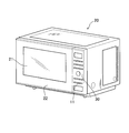
- FIG. 1 is an external perspective view of a microwave oven (electronic device) as an example having the operating device according to the first embodiment of the present invention.
- FIG. 2 is a front view of the operation buttons of the operation device.
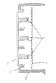
- FIG. 3 is a longitudinal sectional view of an operation switch portion of the operation device.
- FIG. 4 is a longitudinal sectional view of the vicinity of the convex portion of the operating device.
- FIG. 5 is a cross-sectional view of the operation switch portion of the operation device before the bow is deformed.
- FIG. 6 is a cross-sectional view of the operation switch unit of the operating device after the bow is deformed.
- a microwave oven 20 as an electronic device is provided with a heating chamber 21 for storing a heated object such as food in order to cook food.
- a side opening 22 for opening and closing the heated object outlet is provided at the heated object outlet formed on the front surface of the heating chamber 21.
- a viewing window is formed at the center of the door 22 so that the heating status of the object to be heated during cooking can be confirmed.
- a machine room is provided on the right side of the microwave oven 20 from the front.
- a magnetron (not shown), which is a high-frequency generator, is provided in the machine room, and high-frequency power generated by the magnetron propagates through the waveguide and is supplied into the heating chamber 21. Has been.
- An operation panel 30 as an operation device is installed adjacent to the door 22 on the front side of the microwave oven 20 and on the right side of the door 22.
- the operation panel 30 includes an operation unit 12, an operation board 14, and operation buttons 11.
- An operation sheet 15 is affixed to the front surface of the operation unit 12 and the side operated by the user of the microwave oven 20, and the operation sheet 15 is a display for explaining functions assigned to the operation buttons 11. Is printed.
- the operation unit 12 is made of polycarbonate ABS resin.
- five operation button insertion openings 18 (openings) are formed in a long hole shape in the up-down direction across the width direction of the operation unit 12. The user can select a cooking menu and start heating by pressing the operation button 11 of the operation unit 12.
- a rib-shaped peripheral edge 17 is formed on the entire rear surface of the operation button insertion opening 18 on the rear surface side of the operation button insertion opening 18.
- the polycarbonate ABS resin is used as the material of the operation unit 12, but other resins may be used.
- the operation board 14 is attached to the operation unit 12.
- the operation board 14 is equipped with an operation switch 13 using 14 tact switches and a liquid crystal display panel (not shown) on the front side (operation side) of the microwave oven 20.
- the operation switch 13 is installed to face an operation button 11 described later.
- a circuit pattern is printed on the rear surface of the operation board 14 and wired to an IC (not shown). Then, input processing is performed by operating the operation switch 13 with the operation board 14, and a signal is output to the control device on another substrate, and a signal from the control device is input to the liquid crystal display panel. The operation contents of 13 and the progress status of the selected cooking contents (time until the end of cooking, etc.) are displayed.
- the operation button 11 is manufactured by injection molding of ABS resin and is attached to the operation unit 12.
- the operation buttons 11 are arranged side by side on the operation unit 12, and the gaps between the operation buttons 11 have a possible gap in mold molding.
- a similar arrangement is also formed in five stages in the vertical direction.
- Each operation button 11 is formed with a hinge mechanism that operates independently. For example, when the user presses a certain operation button 11, the surrounding operation buttons 11 do not move, and only the pressed operation button 11 is pushed backward.
- a convex portion 16 that protrudes forward at a predetermined height in a rib shape is provided near the center of the two operation buttons 11 at both ends. Are formed in the vertical direction so as to be orthogonal to each other. And the convex part 16 is similarly formed also in the other step
- the operation button 11 in which a plurality of operation buttons are integrally formed is inserted into the operation button insertion opening 18 from the rear to the front of the operation unit 12.
- the convex portion 16 formed integrally with the operation button 11 interferes with the peripheral portion 17 of the operation button insertion opening 18 (the convex portion 16 abuts on the peripheral portion 17).
- the operation button 11 formed with the hinge mechanism inevitably moves backward (rightward in FIG. 4) (the operation button 11 is pushed backward by the peripheral edge portion 17).
- each operation button 11 is individually movable, and therefore, the center side of the operation button 11 is moved (rotated) backward with the end side of the operation button 11 as an axis.
- the protruding heights of the surfaces of the operation buttons 11 coincide with each other. Unevenness can be eliminated and the appearance can be improved.
- an operation switch 13 using a tact switch installed on the opposite surface is turned on, and an operation board 14 on which the operation switch 13 is installed is operated by an IC (FIG. A signal is transmitted to (not shown) and control is performed.
- the peripheral edge 17 of the operation button insertion opening 18 of the operation unit 12 is provided in the operation panel 30 having the integrated operation buttons 11 arranged side by side without any gaps.
- the convex portion 16 formed integrally with the operation button 11 it becomes possible to move one end of the operation button 11 backward, so that the gap between the adjacent operation buttons 11 can be narrowed. become. That is, since it is not necessary to make the operation buttons 11 arranged side by side independent from each other, it is possible to reduce the number of parts and improve the assemblability.
- the present invention is not limited to the microwave oven, and the field having an operating device that performs electronic control is used. It can also be applied to applications.
- the operation device according to the present invention since the operation device according to the present invention relates to the optimum shape of the operation button, it can be applied to applications such as a field having an operation device having a similar button layout.
Landscapes
- Push-Button Switches (AREA)
- Rotary Switch, Piano Key Switch, And Lever Switch (AREA)
Abstract
操作パネルは、操作基板を支持する操作部と、操作部に支持され、2個以上横並びに一体化され操作選択をするための操作ボタンと、操作基板上にあり、操作ボタンと同軸上に配置された操作スイッチと、操作部の操作ボタンを配設するための開口部と、開口部の周囲に配置された周縁部を備える。操作ボタンの端面側のボタンに、周縁部に先当たりする凸部を設け、操作ボタンを故意に弓形に反らせる。
Description
本発明は、電子機器における操作部を構成する操作装置に関するものである。
近年、音響機器、映像機器をはじめ、電子レンジなどの家電製品にいたるまで、電子機器の操作パネルには、操作部と独立した操作ボタン構成が、広く用いられている。
これらの独立した操作ボタンは、複数個のボタンがそれぞれ離れた場所に位置する構成や、横並びに平行に隙間なく並んだ構成のものが、一般的に知られている(例えば、特許文献1参照)。また複数個のボタンが、離れた場所に位置されるボタン構成においては、複数個のボタンを、一体に成型した樹脂を用いることは、比較的容易にボタンの平行度等、外観上の課題を解決することが可能である。
図7は、従来の操作装置を示した外観斜視図である。図7に示すように、操作ボタン11は、操作部12から独立した構成である。各操作ボタン11は、操作部12に開けられた各ボタン用の開口部により、独立して外観表面に突出している。また、操作部12の前面には、操作シート15を貼り付けている。
図8は、本構成の操作装置における操作ボタンの一例を示す正面図である。図8に示すように、複数個のボタンが、ある一定の距離を保って、それぞれ位置するボタンレイアウトにおいては、操作ボタンを一体に構成することは比較的容易に解決できる。
しかしながら、横並びに平行に隙間なく並んだボタン構成においては、図7のような操作ボタン11を一体にすることは、成型上の問題があり、ボタン間の隙間をある程度(一般的には1mm程度)発生してしまう。この問題を解決するため、一般的には各ボタンを独立した部品構成にすることが、広く用いられている。
図9は、複数個のボタンを横並びに、隙間なく並べたボタンレイアウトを有した外観斜視図である。図9に示すように、操作ボタン11は、隣り合う操作ボタン11との隙間が少ない構成である。本構成を実現するため、図10に示すように、各操作ボタン11a、11b、11cは、それぞれ独立して操作部12に配設されている。また、操作基板14は操作部12に支持されている。そして、この操作基板14には、操作ボタン11の対向面側に、操作スイッチ13が配設されている。
しかしながら、横並びに平行に隙間なく並んだ操作ボタン11構成において、各操作ボタン11を独立した部品構成にすることは、成型部品点数の増加、組立作業の増加など、コスト面や組立工数の問題が介在していた。それを解決するためには、各操作ボタン11を一体に成型することが必要であるが、一体に成型することにより、成型上の問題から、隣り合う各操作ボタン11の隙間が大きくなる課題を有してしまう。
本発明は、前記従来の課題を解決するもので、横並びに平行に隙間なく並んだ操作ボタン構成において、各操作ボタンを一体に成型し、すなわち1部品構成とし、また、その弊害である隣り合うボタンの隙間を小さくすることにより、部品点数の減少、組立の簡易化を行うことを可能にした操作装置を提供することを目的とする。
前記従来の課題を解決するために、本発明の操作装置は、電子機器を制御する操作基板と、前記操作基板を支持する操作部と、前記操作部に支持され、2個以上横並びに一体化された操作選択をするための操作ボタンと、前記操作基板上に取り付けられ前記操作ボタンの対向面に配置された操作スイッチと、前記操作部の前記操作ボタンを配設するための開口部と、前記開口部の周囲に配置された周縁部を備え、前記操作ボタンの端面側のボタンに、前記周縁部に先当たりする凸部を設け、前記操作ボタンを故意に弓形に反らせる構成としたものである。
上記発明によれば、操作ボタンを弓形上に反らせることにより、隣り合う各ボタンの隙間を小さくすることが可能になり、すなわち複数個のボタンが横並びに隙間なく並んだ形状を1部品で形成することができるため、部品点数の減少、組立の簡易化が可能となる。
本発明の操作装置によれば、操作ボタンの隣り合うボタン間の隙間を小さくすることが可能になり、すなわち複数個のボタンが横並びに隙間なく並んだ形状を1部品で形成することができるため、部品点数の減少、組立の簡易化が可能となる。
第1の発明は、電子機器を制御する操作基板と、前記操作基板の操作側に配置され前記操作基板を支持する操作部と、前記操作部に支持され直線状に接続された複数個の操作ボタンと、前記操作基板上に搭載され前記操作ボタンの対向面に配置された操作スイッチと、前記操作ボタンを配設するため前記操作部に形成された開口部と、前記開口部の周囲でかつ前記操作ボタン方向に突出して形成した周縁部と、を備え、前記操作ボタンの端面側のボタンに前記周縁部に先当たりする凸部を設け、前記操作ボタンを故意に弓形に反らせることにより、前記操作ボタンの隣り合う各ボタンの隙間を小さくすることが可能となり、操作ボタンの部品点数の減少、組立の簡易化を行うことができる。
第2の発明は、特に第1の発明の操作装置において、前記操作ボタンは、弓形に反らせた形状に合わせて、隣り合う各ボタンの凸部を弓形に反らせた状態で平面になるように、予め各ボタンを凹凸に構成することにより、各ボタンの凸部のボタン間の差異がなくなり、外観の向上、および使用者の操作感を向上させることができる。
第3の発明は、特に第1又は第2の発明の操作装置において、2個以上横並びに配設された前記操作ボタンが、縦方向に複数個一体に構成することにより、複数個の操作ボタンレイアウトが可能になり、デザイン性の向上および、更なる部品点数の減少、組立の簡易化が可能になる。
以下、本発明の実施の形態について、図面を参照しながら説明する。なお、この実施の形態によって、本発明が限定されるものではない。
(実施の形態1)
図1は、本発明の第1の実施の形態における操作装置を有した一例としての電子レンジ(電子機器)の外観斜視図である。図2は、同操作装置の操作ボタンの正面図である。図3は、同操作装置の操作スイッチ部の縦断面図である。図4は、同操作装置の凸部近傍の縦断面図である。図5は、同操作装置の操作スイッチ部における弓形変形前の状態の横断面図である。図6は、同操作装置の操作スイッチ部における弓形変形後の状態の横断面図である。
図1は、本発明の第1の実施の形態における操作装置を有した一例としての電子レンジ(電子機器)の外観斜視図である。図2は、同操作装置の操作ボタンの正面図である。図3は、同操作装置の操作スイッチ部の縦断面図である。図4は、同操作装置の凸部近傍の縦断面図である。図5は、同操作装置の操作スイッチ部における弓形変形前の状態の横断面図である。図6は、同操作装置の操作スイッチ部における弓形変形後の状態の横断面図である。
同図において、電子機器としての電子レンジ20には、食材の加熱調理を行うため、食品のような被加熱物を収容する加熱室21が設けられている。この加熱室21の前面に形成された被加熱物取出口には、被加熱物取出口を開閉する横開きの扉22が設けられている。この扉22の中央部には、覗き窓が形成され、調理中の被加熱物の加熱状況を確認することができる。
また、電子レンジ20の正面から向かって右側部には、機械室が設けられている。この機械室内には、高周波発生装置であるマグネトロン(図示せず)が設けられ、このマグネトロンで発生した高周波電力は、導波管を伝播して、加熱室21内へ、供給されるように構成されている。
電子レンジ20の前面でかつ扉22の右側には、操作装置としての操作パネル30が、扉22に隣り合って設置されている。そして、操作パネル30は、操作部12と、操作基板14と、操作ボタン11とを備えている。操作部12の前面、電子レンジ20の使用者が操作する側には、操作シート15が貼付されており、この操作シート15には、各操作ボタンに11に割り当てられた機能等を説明する表示が印刷されている。
操作部12は、ポリカーボネートABS樹脂で、形成されている。そして、操作部12の前面には、操作ボタン挿入用開口部18(開口部)が、操作部12の幅方向にわたって、上下方向に5つ、長孔状に形成されている。使用者は、操作部12の操作ボタン11を押すことにより、調理メニュー選択および加熱開始を行うことができる。
また、この操作ボタン挿入用開口部18の後面側には、操作ボタン挿入用開口部18の全周に、リブ状の周縁部17が形成されている。なお、本実施の形態では、操作部12の材料として、ポリカーボネートABS樹脂を用いたが、その他の樹脂を用いても構わない。
操作基板14は、操作部12に取り付けられている。そして、操作基板14は、電子レンジ20の前面側(操作側)に、14個のタクトスイッチを用いた操作スイッチ13と、液晶表示パネル(図示せず)とを搭載している。操作スイッチ13は、後述する操作ボタン11に、それぞれ対向して設置されている。
操作基板14の後面には回路パターンが印刷され、IC(図示せず)に配線されている。そして、操作基板14により、操作スイッチ13を操作することによる入力処理を行い、別基板の制御装置へ信号を出力するとともに、制御装置からの信号を入力して、前記液晶表示パネルに、操作スイッチ13の操作内容や選択した調理内容の進行状況(調理終了までの時間等)を表示する。
また、操作ボタン11は、ABS樹脂を射出成型することにより製造され、操作部12に取り付けられている。そして、操作ボタン11は、操作部12に横並びに3個並んだ構造であり、各操作ボタン11間の隙間は、金型成型上、可能な隙間を有した形状となっている。また、同様の配列が、縦方向にも5段形成されている。
各操作ボタン11は、それぞれ独立して動作するヒンジ機構が形成されている。例えば、使用者がある操作ボタン11を押すと、その周囲の操作ボタン11は動かないで、押した操作ボタン11のみが後方へ押し下げられる構造になっている。
また、横並びに並列された3個の操作ボタン11のうち、両端の2個の操作ボタン11の中央寄りには、リブ状に前方へ所定の高さで突出した凸部16が、操作ボタン11と直交するように上下方向に、形成されている。そして、3個の操作ボタン11が並列された他の段も、凸部16が同様に形成されている。操作ボタン11が2個だけ並設された最下段については、2個の操作ボタン11両方の中央側にそれぞれ凸部16が、形成されている。
以上のように構成された操作装置について、以下その取り付けを説明する。
図4に示すように、複数の操作ボタンが一体に構成された操作ボタン11は、操作ボタン挿入用開口部18に、操作部12の後方から前方へ挿入されている。この時、操作ボタン11と一体に形成された凸部16が、操作ボタン挿入用開口部18の周縁部17に干渉する(凸部16が周縁部17に当接する)。
ヒンジ機構が形成された操作ボタン11は、必然的に後方(図4の右方向)に、移動することになる(操作ボタン11が周縁部17により後方に押される)。前述のように、各操作ボタン11は、それぞれ単独で可動であるため、操作ボタン11の端部側を軸に、操作ボタン11の中央側を後方へ移動(回動)させている。
横並び状態で操作ボタン11を見ると、操作ボタン11に並んで設けられたリブ状凸部16近傍の操作ボタン11が、凸部16の高さだけ、後方へ移動(回動)した状態になる。これにより、横並びの操作ボタン11間の隙間が、成型時に比べ狭くなる。
また、操作ボタン11の前方への突出高さが略同じになるよう、凸部16と周縁部17の高さを設定することにより、操作ボタン11の表面の突出高さが、相互に一致し、凸凹がなくなり、外観上の美観を向上できる。
また、操作ボタン11と操作部12の周縁部17とが近接し隙間を狭くすることにより、操作ボタン挿入用開口部18から水が浸入し、操作基板14に浸水しにくくでき、誤動作が発生することを防止できる。
以上のように構成された操作装置について、以下その動作及び作用を説明する。
操作部12に支持された操作ボタン11を押すと、その対向面に設置されたタクトスイッチを用いた操作スイッチ13がONし、この操作スイッチ13が設置されている操作基板14により、IC(図示せず)に信号が伝達され、制御が行われることになる。
以上のように、本実施の形態によれば、横並びに複数個隙間なく並列した一体型の操作ボタン11を有する操作パネル30において、操作部12の操作ボタン挿入用開口部18の周縁部17に、操作ボタン11に一体に形成された凸部16を干渉させることにより、操作ボタン11の一端を後方に移動させることが可能となるため、隣り合う操作ボタン11間の隙間を狭くすることが可能になる。すなわち、横並びの操作ボタン11を、それぞれ独立したボタンにする必要がなくなるため、部品点数の減少および組立性の向上を実現することが可能となる。
なお、本実施の形態において、本発明の操作装置を電子機器である電子レンジに適用した例を述べたが、電子レンジに限定されるものではなく、電子制御を行う操作装置を持つ分野等の用途にも適用可能である。
本発明を詳細にまた特定の実施態様を参照して説明したが、本発明の精神と範囲を逸脱することなく様々な変更や修正を加えることができることは当業者にとって明らかである。
本出願は、2011年8月23日出願の日本特許出願(特願2011-181239)に基づくものであり、その内容はここに参照として取り込まれる。
以上のように、本発明にかかる操作装置は、操作ボタンの最適形状に関するものであるため、同様のボタンレイアウトを有する操作装置を持つ分野等の用途にも適用可能である。
11 操作ボタン
12 操作部
13 操作スイッチ
14 操作基板
15 操作シート
16 凸部
17 周縁部
18 操作ボタン挿入用開口部(開口部)
20 電子レンジ
21 加熱室
22 扉
30 操作パネル(操作装置)
12 操作部
13 操作スイッチ
14 操作基板
15 操作シート
16 凸部
17 周縁部
18 操作ボタン挿入用開口部(開口部)
20 電子レンジ
21 加熱室
22 扉
30 操作パネル(操作装置)
Claims (3)
- 電子機器を制御する操作基板と、
前記操作基板の操作側に配置され前記操作基板を支持する操作部と、
前記操作部に支持され直線状に接続された複数個の操作ボタンと、
前記操作基板上に搭載され前記操作ボタンの対向面に配置された操作スイッチと、
前記操作ボタンを配設するため前記操作部に形成された開口部と、前記開口部の周囲でかつ前記操作ボタン方向に突出して形成した周縁部と、を備え、
前記操作ボタンの端面側のボタンに前記周縁部に先当たりする凸部を設け、前記操作ボタンを故意に弓形に反らせることにより、前記操作ボタンの隣り合う各ボタンの隙間を小さくすることを特徴とした操作装置。 - 前記操作ボタンは、弓形に反らせた形状に合わせて、隣り合う各ボタンの凸部を弓形に反らせた状態で平面になるように、予め各ボタンを凹凸に構成した請求項1に記載の操作装置。
- 2個以上横並びに配設された前記操作ボタンが、縦方向に複数個一体に構成された請求項1または2に記載の操作装置。
Priority Applications (1)
| Application Number | Priority Date | Filing Date | Title |
|---|---|---|---|
| EP12824977.8A EP2733715B1 (en) | 2011-08-23 | 2012-08-16 | Operating device |
Applications Claiming Priority (2)
| Application Number | Priority Date | Filing Date | Title |
|---|---|---|---|
| JP2011-181239 | 2011-08-23 | ||
| JP2011181239A JP5671704B2 (ja) | 2011-08-23 | 2011-08-23 | 操作装置 |
Publications (1)
| Publication Number | Publication Date |
|---|---|
| WO2013027376A1 true WO2013027376A1 (ja) | 2013-02-28 |
Family
ID=47746145
Family Applications (1)
| Application Number | Title | Priority Date | Filing Date |
|---|---|---|---|
| PCT/JP2012/005172 Ceased WO2013027376A1 (ja) | 2011-08-23 | 2012-08-16 | 操作装置 |
Country Status (3)
| Country | Link |
|---|---|
| EP (1) | EP2733715B1 (ja) |
| JP (1) | JP5671704B2 (ja) |
| WO (1) | WO2013027376A1 (ja) |
Citations (4)
| Publication number | Priority date | Publication date | Assignee | Title |
|---|---|---|---|---|
| JPS54120328U (ja) * | 1978-02-09 | 1979-08-23 | ||
| JPS6294522U (ja) * | 1985-12-03 | 1987-06-16 | ||
| JPH07302526A (ja) * | 1994-04-28 | 1995-11-14 | Teikoku Tsushin Kogyo Co Ltd | キートップ板 |
| JP2006269286A (ja) | 2005-03-24 | 2006-10-05 | Denso Corp | 押しボタンスイッチ |
Family Cites Families (2)
| Publication number | Priority date | Publication date | Assignee | Title |
|---|---|---|---|---|
| GB2364021B (en) * | 2000-06-30 | 2003-06-18 | Nokia Mobile Phones Ltd | Keypad and electronic device |
| JP2003331689A (ja) * | 2002-05-15 | 2003-11-21 | Alps Electric Co Ltd | スイッチ装置 |
-
2011
- 2011-08-23 JP JP2011181239A patent/JP5671704B2/ja active Active
-
2012
- 2012-08-16 EP EP12824977.8A patent/EP2733715B1/en active Active
- 2012-08-16 WO PCT/JP2012/005172 patent/WO2013027376A1/ja not_active Ceased
Patent Citations (4)
| Publication number | Priority date | Publication date | Assignee | Title |
|---|---|---|---|---|
| JPS54120328U (ja) * | 1978-02-09 | 1979-08-23 | ||
| JPS6294522U (ja) * | 1985-12-03 | 1987-06-16 | ||
| JPH07302526A (ja) * | 1994-04-28 | 1995-11-14 | Teikoku Tsushin Kogyo Co Ltd | キートップ板 |
| JP2006269286A (ja) | 2005-03-24 | 2006-10-05 | Denso Corp | 押しボタンスイッチ |
Non-Patent Citations (1)
| Title |
|---|
| See also references of EP2733715A4 * |
Also Published As
| Publication number | Publication date |
|---|---|
| EP2733715A1 (en) | 2014-05-21 |
| JP2013045539A (ja) | 2013-03-04 |
| JP5671704B2 (ja) | 2015-02-18 |
| EP2733715B1 (en) | 2016-06-29 |
| EP2733715A4 (en) | 2015-04-22 |
Similar Documents
| Publication | Publication Date | Title |
|---|---|---|
| EP3037760B1 (en) | Touch sensor assembly and method of manufacturing the same | |
| EP2337225B1 (en) | Icon illumination for capacitive touch switch | |
| KR101662941B1 (ko) | 조리기기 및 조리기기의 터치 센서 어셈블리 | |
| US9732963B2 (en) | Appliance control panel assembly | |
| CN105805783A (zh) | 烹调装置 | |
| KR101680969B1 (ko) | 컨트롤 어셈블리 및 컨트롤 어셈블리가 구비된 조리 기기 | |
| EP3077583B1 (en) | A household appliance comprising a light guide | |
| JP5671704B2 (ja) | 操作装置 | |
| US9666388B2 (en) | Control panel for an appliance | |
| KR102128908B1 (ko) | 리모컨 장치 | |
| KR100487151B1 (ko) | 전자렌지 | |
| KR19990017335U (ko) | 전자렌지용 버튼의 구조 | |
| KR20060135534A (ko) | 가열 조리기 | |
| KR100760401B1 (ko) | 전자레인지용 다이얼노브 | |
| KR20060063146A (ko) | 전기오븐의 인쇄회로기판 장착구조 | |
| KR200220809Y1 (ko) | 박판 필름이 있는 케이스부품의 버튼장치(Button Device for Use with Case Unit Having Sheet Material) | |
| EP2797476B1 (en) | A household appliance | |
| US11757447B2 (en) | Sensor element device for an operating device, operating device and electrical appliance having such an operating device | |
| KR101297992B1 (ko) | Pcb 모듈 | |
| CN100455902C (zh) | 微波炉用控制部 | |
| JP2012048875A (ja) | 加熱調理器 | |
| EP2292135B1 (en) | A control panel for a domestic appliance | |
| KR20040049479A (ko) | 전자렌지 | |
| KR20030079363A (ko) | 전자레인지의 컨트롤러 조립체 | |
| KR200386575Y1 (ko) | 전기오븐의 컨트롤패널 |
Legal Events
| Date | Code | Title | Description |
|---|---|---|---|
| 121 | Ep: the epo has been informed by wipo that ep was designated in this application |
Ref document number: 12824977 Country of ref document: EP Kind code of ref document: A1 |
|
| WWE | Wipo information: entry into national phase |
Ref document number: 2012824977 Country of ref document: EP |
|
| NENP | Non-entry into the national phase |
Ref country code: DE |