WO2013027627A1 - 燃料電池用電極触媒層、燃料電池用電極、燃料電池用膜電極接合体及び燃料電池 - Google Patents
燃料電池用電極触媒層、燃料電池用電極、燃料電池用膜電極接合体及び燃料電池 Download PDFInfo
- Publication number
- WO2013027627A1 WO2013027627A1 PCT/JP2012/070659 JP2012070659W WO2013027627A1 WO 2013027627 A1 WO2013027627 A1 WO 2013027627A1 JP 2012070659 W JP2012070659 W JP 2012070659W WO 2013027627 A1 WO2013027627 A1 WO 2013027627A1
- Authority
- WO
- WIPO (PCT)
- Prior art keywords
- catalyst layer
- electrode catalyst
- fuel cell
- ionomer
- platinum
- Prior art date
- Legal status (The legal status is an assumption and is not a legal conclusion. Google has not performed a legal analysis and makes no representation as to the accuracy of the status listed.)
- Ceased
Links
Images








Classifications
-
- H—ELECTRICITY
- H01—ELECTRIC ELEMENTS
- H01M—PROCESSES OR MEANS, e.g. BATTERIES, FOR THE DIRECT CONVERSION OF CHEMICAL ENERGY INTO ELECTRICAL ENERGY
- H01M4/00—Electrodes
- H01M4/86—Inert electrodes with catalytic activity, e.g. for fuel cells
- H01M4/8663—Selection of inactive substances as ingredients for catalytic active masses, e.g. binders, fillers
-
- B—PERFORMING OPERATIONS; TRANSPORTING
- B01—PHYSICAL OR CHEMICAL PROCESSES OR APPARATUS IN GENERAL
- B01J—CHEMICAL OR PHYSICAL PROCESSES, e.g. CATALYSIS OR COLLOID CHEMISTRY; THEIR RELEVANT APPARATUS
- B01J23/00—Catalysts comprising metals or metal oxides or hydroxides, not provided for in group B01J21/00
- B01J23/38—Catalysts comprising metals or metal oxides or hydroxides, not provided for in group B01J21/00 of noble metals
- B01J23/40—Catalysts comprising metals or metal oxides or hydroxides, not provided for in group B01J21/00 of noble metals of the platinum group metals
- B01J23/42—Platinum
-
- B—PERFORMING OPERATIONS; TRANSPORTING
- B01—PHYSICAL OR CHEMICAL PROCESSES OR APPARATUS IN GENERAL
- B01J—CHEMICAL OR PHYSICAL PROCESSES, e.g. CATALYSIS OR COLLOID CHEMISTRY; THEIR RELEVANT APPARATUS
- B01J35/00—Catalysts, in general, characterised by their form or physical properties
- B01J35/30—Catalysts, in general, characterised by their form or physical properties characterised by their physical properties
- B01J35/33—Electric or magnetic properties
-
- B—PERFORMING OPERATIONS; TRANSPORTING
- B01—PHYSICAL OR CHEMICAL PROCESSES OR APPARATUS IN GENERAL
- B01J—CHEMICAL OR PHYSICAL PROCESSES, e.g. CATALYSIS OR COLLOID CHEMISTRY; THEIR RELEVANT APPARATUS
- B01J35/00—Catalysts, in general, characterised by their form or physical properties
- B01J35/30—Catalysts, in general, characterised by their form or physical properties characterised by their physical properties
- B01J35/391—Physical properties of the active metal ingredient
- B01J35/392—Metal surface area
-
- H—ELECTRICITY
- H01—ELECTRIC ELEMENTS
- H01M—PROCESSES OR MEANS, e.g. BATTERIES, FOR THE DIRECT CONVERSION OF CHEMICAL ENERGY INTO ELECTRICAL ENERGY
- H01M4/00—Electrodes
- H01M4/86—Inert electrodes with catalytic activity, e.g. for fuel cells
- H01M4/8605—Porous electrodes
-
- H—ELECTRICITY
- H01—ELECTRIC ELEMENTS
- H01M—PROCESSES OR MEANS, e.g. BATTERIES, FOR THE DIRECT CONVERSION OF CHEMICAL ENERGY INTO ELECTRICAL ENERGY
- H01M4/00—Electrodes
- H01M4/86—Inert electrodes with catalytic activity, e.g. for fuel cells
- H01M4/8663—Selection of inactive substances as ingredients for catalytic active masses, e.g. binders, fillers
- H01M4/8668—Binders
-
- H—ELECTRICITY
- H01—ELECTRIC ELEMENTS
- H01M—PROCESSES OR MEANS, e.g. BATTERIES, FOR THE DIRECT CONVERSION OF CHEMICAL ENERGY INTO ELECTRICAL ENERGY
- H01M4/00—Electrodes
- H01M4/86—Inert electrodes with catalytic activity, e.g. for fuel cells
- H01M4/90—Selection of catalytic material
- H01M4/92—Metals of platinum group
-
- H—ELECTRICITY
- H01—ELECTRIC ELEMENTS
- H01M—PROCESSES OR MEANS, e.g. BATTERIES, FOR THE DIRECT CONVERSION OF CHEMICAL ENERGY INTO ELECTRICAL ENERGY
- H01M4/00—Electrodes
- H01M4/86—Inert electrodes with catalytic activity, e.g. for fuel cells
- H01M4/90—Selection of catalytic material
- H01M4/92—Metals of platinum group
- H01M4/925—Metals of platinum group supported on carriers, e.g. powder carriers
-
- H—ELECTRICITY
- H01—ELECTRIC ELEMENTS
- H01M—PROCESSES OR MEANS, e.g. BATTERIES, FOR THE DIRECT CONVERSION OF CHEMICAL ENERGY INTO ELECTRICAL ENERGY
- H01M8/00—Fuel cells; Manufacture thereof
- H01M8/10—Fuel cells with solid electrolytes
- H01M8/1007—Fuel cells with solid electrolytes with both reactants being gaseous or vaporised
-
- H—ELECTRICITY
- H01—ELECTRIC ELEMENTS
- H01M—PROCESSES OR MEANS, e.g. BATTERIES, FOR THE DIRECT CONVERSION OF CHEMICAL ENERGY INTO ELECTRICAL ENERGY
- H01M8/00—Fuel cells; Manufacture thereof
- H01M8/10—Fuel cells with solid electrolytes
- H01M2008/1095—Fuel cells with polymeric electrolytes
-
- Y—GENERAL TAGGING OF NEW TECHNOLOGICAL DEVELOPMENTS; GENERAL TAGGING OF CROSS-SECTIONAL TECHNOLOGIES SPANNING OVER SEVERAL SECTIONS OF THE IPC; TECHNICAL SUBJECTS COVERED BY FORMER USPC CROSS-REFERENCE ART COLLECTIONS [XRACs] AND DIGESTS
- Y02—TECHNOLOGIES OR APPLICATIONS FOR MITIGATION OR ADAPTATION AGAINST CLIMATE CHANGE
- Y02E—REDUCTION OF GREENHOUSE GAS [GHG] EMISSIONS, RELATED TO ENERGY GENERATION, TRANSMISSION OR DISTRIBUTION
- Y02E60/00—Enabling technologies; Technologies with a potential or indirect contribution to GHG emissions mitigation
- Y02E60/30—Hydrogen technology
- Y02E60/50—Fuel cells
Definitions
- the present invention relates to a fuel cell electrode catalyst layer, a fuel cell electrode, a fuel cell membrane electrode assembly, and a fuel cell. More specifically, the present invention provides a fuel that can achieve good current-voltage characteristics while achieving both gas transport properties and proton transport properties such as oxidant gas and fuel gas even when the platinum loading is lowered.
- the present invention relates to an electrode catalyst layer for a battery, an electrode for a fuel cell, a membrane electrode assembly for a fuel cell, and a fuel cell.
- Such a fuel cell can be applied to a vehicle, for example.
- An example of such a fuel cell is a polymer electrolyte fuel cell (PEFC).
- a polymer electrolyte fuel cell generally has a structure in which a plurality of single cells that exhibit a power generation function are stacked.
- Each single cell has a polymer electrolyte membrane and a membrane electrode assembly (MEA).
- the MEA includes a pair of electrode catalyst layers that sandwich a polymer electrolyte membrane from the anode side and the cathode side.
- Examples of the polymer electrolyte membrane include Nafion (registered trademark, manufactured by DuPont).
- Each single cell further includes a membrane electrode gas diffusion layer assembly including a pair of gas diffusion layers (GDL) for sandwiching the membrane electrode assembly and dispersing the supply gas on the anode side and the cathode side, respectively.
- GDL gas diffusion layers
- a fuel cell stack is configured by stacking and connecting single cells in this manner.
- the fuel cell stack can function as power generation means that can be used for various applications.
- the power generation mechanism of the polymer electrolyte fuel cell will be briefly explained.
- a fuel gas such as hydrogen gas is supplied to the anode side of the single cell, and an oxidant gas such as air or oxygen is supplied to the cathode side.
- an electrochemical reaction represented by the following reaction formulas (1) and (2) proceeds to generate electricity.
- platinum is used as a catalyst component for promoting the electrochemical reaction represented by the above reaction formulas (1) and (2).
- This membrane electrode assembly is a membrane electrode assembly in which catalyst electrodes are joined to both surfaces of an electrolyte membrane, and at least one of the catalyst electrodes includes first and second catalyst layers containing a catalyst, carbon, and ionomer. .
- the weight ratio of ionomer to carbon in the second catalyst layer is 0.4 to 0.75.
- the present invention has been made to solve the above problems. That is, the present invention provides an electrode for a fuel cell that can achieve good current-voltage characteristics while achieving both gas transportability and proton transportability of oxidant gas, fuel gas, etc., even when the platinum loading is lowered.
- An object is to provide a catalyst layer. It is another object of the present invention to provide a fuel cell electrode, a fuel cell membrane electrode assembly and a fuel cell using such a fuel cell electrode catalyst layer.
- An electrode catalyst layer for a fuel cell includes an electrode catalyst having a conductive support and platinum-containing metal particles supported on the surface of the conductive support, and an ionomer that covers the electrode catalyst.
- the average thickness of the ionomer is 2.4 nm or less.
- the fuel cell electrode according to an aspect of the present invention is characterized by having the fuel cell electrode catalyst layer of the present invention.
- a fuel cell membrane electrode assembly according to an aspect of the present invention is characterized by having the fuel cell electrode of the present invention.
- a fuel cell according to an aspect of the present invention is characterized by including the membrane electrode assembly for a fuel cell of the present invention.
- FIG. 1 is a perspective view schematically showing a stack of a polymer electrolyte fuel cell which is a representative example of a fuel cell according to an embodiment of the present invention.
- FIG. 2 is a cross-sectional view schematically showing a basic configuration of a polymer electrolyte fuel cell which is a typical example of a fuel cell according to an embodiment of the present invention.
- FIG. 3 is a cross-sectional view schematically showing a configuration of an electrode catalyst layer of a polymer electrolyte fuel cell which is a typical example of a fuel cell according to an embodiment of the present invention.
- FIG. 1 is a perspective view schematically showing a stack of a polymer electrolyte fuel cell which is a representative example of a fuel cell according to an embodiment of the present invention.
- FIG. 2 is a cross-sectional view schematically showing a basic configuration of a polymer electrolyte fuel cell which is a typical example of a fuel cell according to an embodiment of the present invention.
- FIG. 3
- FIG. 4 shows the relative humidity (RH) of the supply gas of the electric double layer capacity (C dl ) of the fuel cell catalyst layer measured using the fuel cell membrane electrode assembly having the fuel cell electrode catalyst layers A and B. It is a graph which shows dependence.
- FIG. 5 is a graph showing the relationship between the effective platinum surface area and the oxygen transport resistance of the electrode catalyst layer when the electrode catalyst layer A (A1s, A2s, A3s) is used.
- FIG. 6 is a graph showing current-voltage characteristics when the electrode catalyst layer A (A1-3, A2-6, A3-3) is used.
- FIG. 7 is a graph showing current-voltage characteristics when the electrode catalyst layer A (A1-1, A2-3, A3-1) is used.
- FIG. 8 is a graph showing current-voltage characteristics when the electrode catalyst layer A (A1-2, A2-5, A3-2) is used.
- FIG. 9 is a graph showing the relationship between the effective platinum surface area and the oxygen transport resistance of the electrode catalyst layer when the electrode catalyst layer B (B1s, B2s, B3s, B4s, etc.) is used.
- FIG. 10 is a graph showing the relationship between the average thickness of the ionomer and the coverage of the ionomer in the conductive carrier.
- FIG. 11 is a diagram for explaining the results of molecular dynamic analysis of the ionomer coating structure in FIG. (A) is a top view, (b) is sectional drawing.
- FIG. 12 is a three-way digital slice image of (a) electrode catalyst C, (b) electrode catalyst D, and (c) electrode catalyst E.
- FIG. 13 is a graph showing the relationship between the electrode catalyst layer thickness and the cell voltage when the platinum effective surface area is the same.
- FIG. 14 is a graph showing the relationship between the platinum metal particle support concentration in the electrode catalyst and the thickness of the electrode catalyst layer.
- FIG. 15 is a graph showing current-voltage characteristics when ionomers of each ion exchange equivalent are applied.
- FIG. 16 is a graph showing current-voltage characteristics when conductive carriers having different amounts of acidic functional groups are applied.
- FIG. 1 is a perspective view schematically showing a stack of a polymer electrolyte fuel cell which is a typical example of a fuel cell according to an embodiment of the present invention.
- FIG. 2 is a cross-sectional view schematically showing a basic configuration of a polymer electrolyte fuel cell which is a typical example of a fuel cell according to an embodiment of the present invention.
- FIG. 3 is a cross-sectional view schematically showing a configuration of an electrode catalyst layer of a polymer electrolyte fuel cell which is a typical example of a fuel cell according to an embodiment of the present invention.
- the fuel cell (stack) 1 includes a membrane electrode assembly 10, a pair of gas diffusion layers (GDL) 20 that sandwich the membrane electrode assembly 10, and a membrane electrode assembly. 10 and a pair of separators 30 sandwiching the gas diffusion layer 20.
- the GDL 20 and the separator 30 are paired on the anode side and the cathode side.
- the membrane electrode assembly exhibits a power generation function, and the gas diffusion layer disperses the supply gas.
- the separator separates the fuel gas and the oxidant gas supplied to the anode and the cathode and electrically connects adjacent membrane electrode assemblies.
- a fuel cell stack is comprised by laminating
- a gas seal portion is disposed between a separator and a solid polymer electrolyte membrane, which will be described later, or between a membrane electrode assembly and another membrane electrode assembly adjacent thereto.
- a manifold functioning as a connecting means for connecting the cells when the stack is formed is disposed, but these descriptions are omitted in FIG.
- the membrane electrode assembly 10 includes a polymer electrolyte membrane 11 and a pair of electrode catalyst layers 13 sandwiching the polymer electrolyte membrane 11.
- the pair of electrode catalyst layers 13 may be referred to as an anode electrode catalyst layer 13a and a cathode electrode catalyst layer 13c, respectively.
- the membrane electrode assembly 10 is sandwiched between a pair of gas diffusion layers (GDL) 20.
- the pair of gas diffusion layers 20 may be referred to as an anode gas diffusion layer 20a and a cathode gas diffusion layer 20c, respectively.
- the membrane electrode assembly 10 and the gas diffusion layer 20 are sandwiched between a pair of separators 30.
- the pair of separators 30 may be referred to as an anode separator 30a and a cathode separator 30c, respectively.
- the separator 30 has an uneven shape as shown in FIG.
- the convex part seen from the membrane electrode assembly 10 side of the separator (30a, 30c) is in contact with the gas diffusion layer 20. Thereby, the electrical connection with the membrane electrode assembly 10 is ensured.
- the recesses of the separators (30a, 30c) viewed from the membrane electrode assembly 10 side function as gas flow paths (GPa, GPc) for flowing gas when the fuel cell (stack) 1 is operated.
- the said recessed part corresponds to the space between the separator 30 and gas diffusion layer 20 which arises due to the uneven
- a fuel gas such as hydrogen is circulated through the gas flow path GPa of the anode separator 30a, and an oxidant gas such as oxygen and air is circulated through the gas flow path GPc of the cathode separator 30c.
- the concave portion viewed from the side opposite to the membrane electrode assembly 10 side of the separator (30a, 30c) is used to cool the fuel cell (stack) with a coolant such as water in order to cool the fuel cell (stack). It functions as a refrigerant channel CP to be circulated.
- a fuel cell electrode is composed of only the electrode catalyst layer or a structure formed by forming an electrode catalyst layer on the gas diffusion layer.
- the electrode catalyst layer 13 of this embodiment includes an electrode catalyst 131 including a conductive carrier 131a and metal particles 131b containing platinum supported on the surface of the conductive carrier 131a, and an electrode catalyst 131.
- An ionomer 133 that covers the surface.
- the conductive carrier 131a has the primary holes a.
- arrows A and B in the figure indicate the movement (flow) of oxygen gas and proton when the electrode catalyst layer 13 is the cathode electrode catalyst layer 13c, respectively.
- the electrode catalyst layer of the present embodiment is highly effective when used as a cathode electrode catalyst layer, but is not limited thereto. For example, it can be used as an anode electrode catalyst layer.
- platinum-containing metal particles can be interpreted to include platinum particles themselves.
- a conductive carrier having primary pores it is preferable to use a conductive carrier having primary pores, but the present invention is not limited to this. That is, although not shown, one having no primary holes can be applied.
- hole a represents the space which the electrode catalyst 131 has in a particle
- hole represents the space which is formed between electrode catalyst particles although it is not illustrated.
- the average thickness of the ionomer in this embodiment is 2.4 nm or less. Even when the amount of platinum supported is further lowered, in order to exhibit better current-voltage characteristics, the thickness is preferably 2.0 nm or less, and more preferably 1.7 nm or less.
- the fuel cell electrode catalyst layer of the present embodiment improves the gas transportability and proton transportability of oxidant gas, fuel gas, etc., even when the amount of platinum supported is lowered. It can be compatible. As a result, good current-voltage characteristics can be exhibited.
- a fuel cell electrode, a fuel cell membrane electrode assembly, and a fuel cell to which the fuel cell electrode catalyst layer is applied that is, even when the amount of platinum supported is lowered, it is possible to improve both the gas transportability and proton transportability of oxidant gas, fuel gas, etc., and to exhibit good current-voltage characteristics.
- the effective surface area of platinum in this embodiment is preferably 120 cm 2 ⁇ cm ⁇ 2 or less. Further, even when the amount of platinum supported is further reduced, it is preferably 100 cm 2 ⁇ cm ⁇ 2 or less in order to exhibit good current-voltage characteristics. However, the present invention is not limited to being within such a suitable numerical range.
- the effective surface area of platinum and the average thickness of ionomer will be described.
- the “effective platinum surface area (S pt eff [cm 2 ⁇ cm ⁇ 2 ])” is the amount of platinum (m [mg pt ⁇ cm ⁇ 2 ]) contained in the electrode catalyst layer for fuel cells, and the electrochemical It is represented by the following formula [1] using the surface area (s eff [m 2 ⁇ g pt ⁇ 1 ]).
- the electrochemical surface area is determined from the amount of electricity corresponding to the hydrogen adsorption amount and CO adsorption amount in cyclic voltammetry, which is a general technique.
- w [ ⁇ ] is a mass ratio of the ionomer to the conductive carrier, and is represented by g_ionomer / g_support .
- ⁇ [ g_ionomer / cm 3 ] is the dry density of the ionomer.
- S [m 2 / g_support ] is the nitrogen (N 2 ) BET specific surface area of the conductive support.
- ⁇ [ ⁇ ] is the ratio of C dl under the low and high humidification conditions determined when evaluating the relative humidity (RH) dependence of the supply gas. Note that low humidification is a humidity condition of RH 30% or less, and may be abbreviated as “dry” hereinafter. Moreover, high humidification means the humidity conditions of RH100%.
- ⁇ [ ⁇ ] is expressed as C dl_dry / C dl_RH 100% .
- C dl is the electric double layer capacity of the fuel cell catalyst layer measured using a fuel cell membrane electrode assembly having a fuel cell catalyst layer formed as a mixture containing a conductive carrier and an ionomer. Represents.
- the dependence of the electric double layer capacity (C dl ) in the fuel cell catalyst layer on the relative humidity of the supply gas is evaluated as follows. That is, the low humidity condition is 30% relative humidity, the high humidity condition is 100% relative humidity, and the ratio of the electric double layer capacity under these conditions is used. The reason is as follows.
- FIG. 4 shows the electric double layer capacity (C dl ) in the fuel cell catalyst layer measured using the fuel cell membrane electrode assembly having the fuel cell electrode catalyst layers A and B, and the relative humidity ( It is a graph which shows the dependence with respect to (RH).
- the fuel cell electrode catalyst layer A is formed using a graphitized ketjen black (GKB) carrier, and the nitrogen BET specific surface area is 151 m 2 / g.
- the fuel cell electrode catalyst layer B is formed using a ketjen black (KB) carrier, and the nitrogen BET specific surface area is 718 m 2 / g.
- Nafion having a dry density of 1.91 g / cm 3 was used as the ionomer, and platinum particles were used as the metal particles.
- FIG. 4 suggests that the electric double layer capacity is substantially constant at a relative humidity of 30% or less. Therefore, in the present invention, the relative humidity of 30% and the relative humidity of 100% are set as representative points of the low humidification condition and the high humidification condition, respectively. Then, by taking the ratio of the electric double layer capacity under both conditions, it was used as an index for evaluating how much the conductive support was covered with the ionomer.
- this gas transport route is a gas transport route for oxygen or the like toward the metal particles containing platinum existing in the surface of the conductive carrier or in the primary vacancies. Therefore, for example, the effect of reducing the average thickness of the ionomer to 2.4 nm or less does not appear.
- the effective surface area of platinum is 120 cm 2 ⁇ cm ⁇ 2 or less, the resistance to transporting gas such as oxygen inside the electrode catalyst layer is remarkably increased.
- transmits an ionomer becomes obvious. That is, the gas transport resistance in the ionomer is rate limiting.
- the gas transportability in a gas transport path of oxygen or the like that passes through the ionomer is improved.
- the proton transportability slightly decreases as the thickness of the ionomer is reduced, but the effect does not become obvious. Therefore, even when the amount of platinum supported is lowered, it is possible to improve both gas transport properties such as oxidant gas and fuel gas and proton transport properties and to exhibit good current-voltage characteristics.
- the effective surface area of platinum in the present embodiment is preferably 5 cm 2 ⁇ cm ⁇ 2 or more from the viewpoint of suppressing voltage drop.
- the present invention is not limited to being within such a suitable numerical range.
- the average thickness of the ionomer in this embodiment is preferably 0.9 nm or more.
- the present invention is not limited to being within such a suitable numerical range.
- FIG. 5 is a graph showing the relationship between the effective platinum surface area and the oxygen transport resistance of the electrode catalyst layer when the electrode catalyst layer A (A1s, A2s and A3s) is used.
- A1s has an ionomer average thickness of 2.4 nm
- A2s has an ionomer average thickness of 3.2 nm
- A3s has an ionomer average thickness of 4.6 nm.
- A3-1 was 38 cm 2 ⁇ cm -2
- A1-1 was 43 cm 2 ⁇ cm -2 .
- All of A1-2, A2-5, and A3-2 were 104 cm 2 ⁇ cm ⁇ 2 .
- A1-3, A2-6, and A3-3 were all 123 cm 2 ⁇ cm -2 .
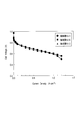
- FIG. 6 is a graph showing current-voltage characteristics when the electrode catalyst layers A1-3, A2-6, and A3-3 are used.
- A1-3 has an effective platinum surface area of 123 cm 2 ⁇ cm ⁇ 2 and an average ionomer thickness of 2.4 nm
- A2-6 has an effective platinum surface area of 123 cm 2 ⁇ cm ⁇ 2 and an average ionomer thickness of 3.2 nm
- A3-3 has a platinum effective surface area of 123 cm 2 ⁇ cm -2 and an ionomer average thickness of 4.6 nm. As shown in FIG. 6, when the platinum effective surface area is large, the effect of reducing the average thickness of the ionomer does not appear.
- the above mechanism is not clear, but it is considered that the improvement in gas transportability such as oxygen and the decrease in proton transportability cancel each other, and the current voltage performance at the maximum current remains low.
- the above mechanism is based on estimation. Therefore, it goes without saying that even if the above-described effect is obtained by a mechanism other than the above-described mechanism, it is included in the scope of the present invention. The same applies to the mechanism described below.
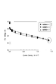
- FIG. 7 is a graph showing the current-voltage characteristics when the electrode catalyst layers A1-1, A2-3 and A3-1 are used.
- A1-1 has an effective platinum surface area of 43 cm 2 ⁇ cm ⁇ 2 and an average ionomer thickness of 2.4 nm
- A2-3 has an effective platinum surface area of 42 cm 2 ⁇ cm ⁇ 2 and an average ionomer thickness of 3.2 nm
- A3-1 has a platinum effective surface area of 38 cm 2 ⁇ cm -2 and an ionomer average thickness of 4.6 nm. As shown in FIG. 7, when the platinum effective surface area is small, the effect of reducing the average thickness of the ionomer becomes obvious.
- the above mechanism is not clear, but it is considered that the improvement in gas transport properties such as oxygen dominates the current-voltage characteristics and the influence of the decrease in proton transport properties is small. Further, the cell voltage when the electrode catalyst layer A1-1 at the highest current is applied is 485 mV, and the cell voltage when the electrode catalyst layer A3-1 is applied is 452 mV, so that the current-voltage performance is 7.3%. It can be seen that it has improved.
- FIG. 8 is a graph showing current-voltage characteristics when the electrode catalyst layer A (A1-2, A2-5, A3-2) is used.
- A1-2 has an effective platinum surface area of 104 cm 2 ⁇ cm -2 and an average ionomer thickness of 2.4 nm
- A2-5 has an effective platinum surface area of 42 cm 2 ⁇ cm -2 and an average ionomer thickness of 3.2 nm
- A3-2 has an effective platinum surface area of 38 cm 2 ⁇ cm -2 and an ionomer average thickness of 4.6 nm.
- the platinum effective surface area is 104 cm 2 ⁇ cm ⁇ 2
- the current-voltage performance at the maximum current in each catalyst layer is equivalent.
- the electrocatalyst layer has primary vacancies having a diameter of 10 nm or less
- it is particularly preferable that the average thickness of the ionomer is 2.0 nm or less.
- hole can be suppressed. Therefore, even when the amount of platinum supported is further reduced, it is possible to achieve both good gas transport properties such as oxidant gas and fuel gas and proton transport properties, and to realize good current-voltage characteristics.
- the average thickness of the ionomer is particularly preferably 1.7 nm or less.
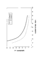
- FIG. 9 is a graph showing the relationship between the effective platinum surface area and the oxygen transport resistance of the electrode catalyst layer when the electrode catalyst layer B (B1s, B2s, B3s, B4s, etc.) is used.
- B1s has an ionomer average thickness of 1.7 nm
- B2s has an ionomer average thickness of 2.0 nm
- B3s has an ionomer average thickness of 2.4 nm
- B4s has an ionomer average thickness of 3.0 nm. The following can be seen from FIG.
- the oxygen transport resistance tends to increase.
- the catalyst layer B2s having an average ionomer thickness of 2 nm when the effective platinum surface area is 120 cm 2 ⁇ cm ⁇ 2 or less, the oxygen transport resistance tends to increase similarly.
- the effective platinum surface area when the effective platinum surface area is 120 cm 2 ⁇ cm ⁇ 2 or less, the average thickness of the ionomer is 2 nm or less, and both excellent oxygen transportability and proton transportability are achieved, and good current-voltage characteristics are obtained. It can be realized.
- the effective platinum surface area is 100 cm 2 ⁇ cm -2 or less, the ionomer thickness is 1.7 nm or less, and both excellent oxygen transportability and proton transportability are achieved, and good current-voltage characteristics are obtained. It can be realized.
- FIG. 10 is a graph showing the relationship between the average thickness of the ionomer and the coverage of the conductive carrier.
- the coverage on the vertical axis is normalized by the value of ( ⁇ ), which is the highest value in the measured value.
- ( ⁇ ) is when the average thickness of the ionomer is 4.0 nm
- ( ⁇ ) is when the average thickness of the ionomer is 2.0 nm
- ( ⁇ ) is an average thickness of the ionomer of 1.0 nm. This corresponds to the case.
- FIG. 11 is a diagram for explaining the result of molecular dynamic analysis of the ionomer coating structure in FIG. (A) is a top view
- (b) is sectional drawing. As shown in FIGS.
- the ratio of the surface area of the metal particles contained in the primary pores of the conductive carrier to the surface area of the metal particles supported on the conductive carrier is 50% or more.
- the ratio of the surface area can be regarded as being equivalent to the ratio of the metal particles present in the primary pores of carbon, and can be calculated as shown in Table 1 from FIG. That is, the proportion of platinum particles present inside the carbon support in Table 1 is equivalent to the proportion of the surface area.
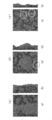
- FIG. 12 is a three-way digital slice image of (a) electrode catalyst C, (b) electrode catalyst D, and (c) electrode catalyst E.
- the electrode catalyst C is in powder form using ketjen black as a conductive carrier and metal particles containing platinum as platinum metal particles.
- the electrode catalyst D is in the form of a catalyst layer using ketjen black as a conductive carrier and metal particles containing platinum as platinum metal particles.
- the electrode catalyst E is in the form of a catalyst layer using acetylene black as a conductive carrier and metal particles containing platinum as platinum metal particles. In each catalyst, platinum metal particles were supported by the same raw material and the same method. Thus, it can be said that FIG. 12 shows the carbon support and platinum supported thereon in a slice image.
- Table 1 shows the measurement results of each parameter for each catalyst.
- the average particle diameter of platinum is the average particle diameter of platinum particles observed in FIG.
- the “total number of platinum particles” is the number of all platinum particles existing in FIG.
- the “ratio of platinum particles present inside the carbon support” is a value obtained by dividing the number of platinum particles inside the carbon support by the total number of platinum particles.
- the ratio of the surface area is considered to be equal to the ratio of the number of particles. That is, in the electrode catalysts C to E, the ratio of the surface area of the metal particles contained in the primary pores of the conductive carrier to the surface area of the platinum particles supported on the conductive carrier is 50% or more. .
- the electrode catalyst layer preferably has a thickness of 5 ⁇ m or less.
- FIG. 13 is a graph showing the relationship between the thickness of the electrode catalyst layer and the cell voltage when the platinum effective surface area is the same.
- FIG. 13 shows that the cell voltage decreases when the thickness of the electrode catalyst layer exceeds 5 ⁇ m. This is considered to be mainly caused by proton transport resistance inside the electrode catalyst layer, that is, IR loss.
- the electrode catalyst layer preferably has a metal particle support concentration of 50% by mass or more in the electrode catalyst. Even with such a configuration, when the platinum loading is lowered, gas transport properties such as oxidant gas and fuel gas and proton transport properties are compatible, and good current-voltage characteristics can be realized. Further, when the supporting concentration is increased in this way, the thickness of the electrode catalyst layer can be reduced even with the same platinum amount, and gas (for example, oxygen) transport in the secondary vacancies of the electrode catalyst layer can be reduced. Since resistance can be reduced, better current-voltage characteristics can be realized.
- FIG. 14 is a graph showing the relationship between the platinum metal particle support concentration in the electrode catalyst and the thickness of the electrode catalyst layer. From FIG. 14, it can be seen that increasing the platinum metal particle support concentration can reduce the thickness of the electrode catalyst layer when the same platinum usage (mg / cm 2 ).
- the ion exchange equivalent (EW) of ionomer in the electrode catalyst layer is preferably 800 or less.
- FIG. 15 is a graph showing current-voltage characteristics when ionomers of each ion exchange equivalent are applied.
- an ion exchange equivalent means the gram number of the electrolyte per 1 mol of acidic functional groups. The number of moles of the acidic functional group can be calculated based on the result of acid-base titration, and the ion exchange equivalent is obtained by dividing the mass of the electrolyte by the number of moles. From FIG. 15, it can be seen that using an ionomer having an ion exchange equivalent of 700, which has an ion exchange equivalent lower than 800, can achieve better current-voltage characteristics than using an ionomer having an ion exchange equivalent of 1000. This is thought to be due to an improvement in proton transportability.
- the conductive support in the electrode catalyst layer has an acidic functional group of 0.34 mmol or more per 1 g of the conductive support.
- the amount of acidic functional group can be determined from the acidity measured by acid-base titration. With such a configuration, water can be retained in the electrode catalyst layer, and proton transport resistance can be further reduced. Therefore, better current-voltage characteristics can be realized.
- FIG. 16 is a graph showing current-voltage characteristics when a conductive carrier having each acidic functional group amount is applied.
- FIG. 16 shows that the use of a conductive carrier having an acidic functional group amount of 0.34 mmol per gram of conductive carrier is a better current voltage than the case of using 0.14 mmol of conductive carrier per gram of conductive carrier. It can be seen that the characteristics can be realized. This is presumably because the moisture content of the electrode catalyst layer when exposed to the same relative humidity increased due to the acidic functional group, and the proton transportability improved.
- the polymer electrolyte membrane 11 has a function of selectively transmitting protons generated in the anode electrode catalyst layer 13a during the operation of the fuel cell (stack) 1 to the cathode electrode catalyst layer 13c along the film thickness direction.
- the solid polymer electrolyte membrane 11 also has a function as a partition wall for preventing the fuel gas supplied to the anode side and the oxidant gas supplied to the cathode side from being mixed.
- the solid polymer electrolyte membrane 11 is roughly classified into a fluorine-based polymer electrolyte membrane and a hydrocarbon-based polymer electrolyte membrane depending on the type of ion exchange resin that is a constituent material.
- ion exchange resins constituting the fluorine-based polymer electrolyte membrane include perfluorocarbon sulfonic acid polymers such as Nafion, Aciplex (registered trademark, manufactured by Asahi Kasei Chemicals Corporation), and FLEION (registered trademark, manufactured by Asahi Glass Co., Ltd.). Is mentioned.
- fluorocarbon phosphonic acid polymers examples include perfluorocarbon phosphonic acid polymers, trifluorostyrene sulfonic acid polymers, ethylene tetrafluoroethylene-g-styrene sulfonic acid polymers, ethylene-tetrafluoroethylene copolymers, and polyvinylidene fluoride-perfluorocarbon sulfonic acids. System polymers and the like. From the viewpoint of improving power generation performance such as heat resistance and chemical stability, these fluorine-based polymer electrolyte membranes are preferably used, and particularly preferably fluorine-based polymer electrolytes composed of perfluorocarbon sulfonic acid polymers. A membrane is used.
- Examples of the ion exchange resin constituting the hydrocarbon electrolyte membrane include sulfonated polyethersulfone (S-PES), sulfonated polyaryletherketone, sulfonated polybenzimidazole alkyl, phosphonated polybenzimidazole alkyl, and sulfonated polystyrene. Sulfonated polyetheretherketone (S-PEEK) and sulfonated polyphenylene (S-PPP). These hydrocarbon polymer electrolyte membranes are preferably used from the viewpoint of production such that the raw material is inexpensive, the production process is simple, and the selectivity of the material is high.
- the ion exchange resin mentioned above only 1 type may be used independently and 2 or more types may be used together. Moreover, it is not limited to the material mentioned above, Other materials can also be used.
- the thickness of the polymer electrolyte membrane may be appropriately determined in consideration of the characteristics of the obtained fuel cell, and is not particularly limited.
- the thickness of the polymer electrolyte membrane is usually 5 to 300 ⁇ m. When the thickness of the polymer electrolyte membrane is within such a numerical range, it is possible to appropriately control the balance of strength during film formation, durability during use, and output characteristics during use.
- the anode electrode catalyst layer 13a and the cathode electrode catalyst layer 13c are layers in which the cell reaction actually proceeds. Specifically, the oxidation reaction of hydrogen proceeds in the anode electrode catalyst layer 13a, and the reduction reaction of oxygen proceeds in the cathode electrode catalyst layer 13c.
- the metal particles 131b used for the anode electrode catalyst layer and containing platinum are not particularly limited as long as they have a catalytic action for the oxidation reaction of hydrogen, and conventionally known catalysts can be applied. Further, the metal particles used in the cathode electrode catalyst layer are not particularly limited as long as they contain platinum and have a catalytic action for the oxygen reduction reaction, and conventionally known catalysts can be similarly used.
- the metal particles include platinum (Pt) simple particles, or platinum particles and ruthenium (Ru), iridium (Ir), rhodium (Rh), palladium (Pd), osmium (Os), tungsten (W), From lead (Pb), iron (Fe), chromium (Cr), cobalt (Co), nickel (Ni), manganese (Mn), vanadium (V), molybdenum (Mo), gallium (Ga) and aluminum (Al)
- grains of the at least 1 sort (s) of other metal chosen from the group which consists of, the alloy of platinum and another metal, etc. can be mentioned.
- a material containing at least platinum is used.
- the composition of the alloy depends on the type of metal to be alloyed, the content of platinum is preferably 30 to 90 atomic% and the content of the metal to be alloyed with platinum is preferably 10 to 70 atomic%.
- an alloy is a generic term for a metal element having one or more metal elements or non-metal elements added and having metallic properties.
- the eutectic alloy which is a mixture of the component elements to form separate crystals, the component elements are completely melted into a solid solution, the component element is an intermetallic compound or a compound of a metal and a nonmetal.
- the metal particles used for the anode electrode catalyst layer and the metal particles used for the cathode electrode catalyst layer can be appropriately selected from the above.
- the metal particles used for the anode electrode catalyst layer and the cathode electrode catalyst layer can be defined similarly. Therefore, they are collectively referred to as “metal particles”.
- the metal particles of the anode electrode catalyst layer and the cathode electrode catalyst layer do not have to be the same, and can be appropriately selected so as to exhibit the desired action as described above.
- the size of the metal particles is not particularly limited, and the same size as a conventionally known catalyst can be adopted.
- the average particle diameter of the metal particles is preferably 1 to 30 nm, more preferably 1 to 2.3 nm.
- the “average particle diameter of the metal particles” in the present invention is the average of the crystallite diameter determined from the half-value width of the diffraction peak of the metal particles in X-ray diffraction or the average particle diameter of the metal particles determined from a transmission electron microscope image. It can be measured as a value.
- the conductive carrier is not particularly limited as long as it functions as a carrier for supporting the above-described metal particles and an electron conduction path material involved in the exchange of electrons between the metal particles and other members. Instead, a conventionally known conductive carrier can be similarly used. Any conductive carrier may be used as long as it has a specific surface area for supporting metal particles in a desired dispersed state and has sufficient electron conductivity, and the main component is preferably carbon.
- carbon examples include acetylene black, channel black, oil (gas) furnace black, lamp black, thermal black, ketjen black and other carbon black, black pearl, graphitized acetylene black, graphitized channel black, graphite Oil (gas) furnace black, graphitized lamp black, graphitized thermal black, graphitized thermal black, graphitized black pearl, carbon nanotube, carbon nanofiber, carbon nanohorn, carbon fibril, activated carbon, coke, natural graphite and artificial Examples thereof include graphite.
- Examples of the oil (gas) furnace black include Vulcan
- examples of the graphitized oil (gas) furnace black include Vulcan.
- the main component is carbon
- the main component contains carbon atoms. In other words, it is used as a concept including both a carbon atom only and a substantially carbon atom. Therefore, in some cases, elements other than carbon atoms may be included in order to improve the characteristics of the fuel cell.
- substantially consisting of carbon atoms means that contamination of 2 to 3 mass% or less of impurities can be allowed.
- the BET specific surface area of the conductive support is preferably a specific surface area sufficient to carry the metal particles in a highly dispersed manner. Specifically, it is preferably 20 to 1600 m 2 / g, more preferably 80 to 1200 m 2 / g. When the specific surface area of the conductive support is within such a numerical range, the balance between the dispersibility of the metal particles on the conductive support and the effective utilization rate of the metal particles as the catalyst component can be appropriately controlled.
- the size of the conductive carrier is not particularly limited, but from the viewpoint of easy loading, utilization as a catalyst for metal particles, and controlling the thickness of the electrode catalyst layer within an appropriate range, the average particle size Is preferably about 5 to 200 nm. More preferably, the average particle size is 10 to 100 nm.
- the supported concentration of the metal particles in the conductive support is preferably 50 to 80% by mass, more preferably 50 to 70% by mass, based on the total amount of the electrode catalyst.
- the concentration of the metal particles supported on the conductive carrier can be measured by inductively coupled plasma emission spectroscopy (ICP).
- Examples of the ionomer include a fluorine-based polymer electrolyte material and a hydrocarbon-based polymer electrolyte material. Depending on the type of ion exchange resin that is a constituent material, the material is roughly classified into a fluorine-based polymer electrolyte material and a hydrocarbon-based polymer electrolyte material.
- the ion exchange resin constituting the fluoropolymer electrolyte material examples include perfluorocarbon sulfonic acid polymers such as Nafion, Aciplex, and Flemion, perfluorocarbon phosphonic acid polymers, trifluorostyrene sulfonic acid polymers, and ethylene tetrafluoro.
- perfluorocarbon sulfonic acid polymers such as Nafion, Aciplex, and Flemion
- perfluorocarbon phosphonic acid polymers examples thereof include an ethylene-g-styrene sulfonic acid polymer, an ethylene-tetrafluoroethylene copolymer, and a polyvinylidene fluoride-perfluorocarbon sulfonic acid polymer.
- these fluorine-based polymer electrolyte materials are preferably used, and perfluorocarbon sulfonic acid polymers are particularly preferably used.
- ion exchange resins constituting hydrocarbon electrolyte materials include sulfonated polyethersulfone (S-PES), sulfonated polyaryletherketone, sulfonated polybenzimidazole alkyl, phosphonated polybenzimidazole alkyl, and sulfonated polystyrene. Sulfonated polyetheretherketone (S-PEEK) and sulfonated polyphenylene (S-PPP). From the viewpoint of production such that the raw material is inexpensive, the production process is simple, and the selectivity of the material is high, these hydrocarbon polymer electrolyte materials are preferably used.
- the ion exchange resin mentioned above only 1 type may be used independently and 2 or more types may be used together. Moreover, it is not limited to the material mentioned above, Other materials can also be used.
- the ion exchange equivalent (EW) of the ionomer in the electrode catalyst layer is preferably 800 or less.
- EW ion exchange equivalent
- the present invention is not limited to being within this preferred numerical range.
- the anode gas diffusion layer 20a and the cathode gas diffusion layer 20c of this embodiment diffuse the fuel gas or oxidant gas supplied through the gas flow paths (GPa, GPc) of the separator to the electrode catalyst layers (13a, 13c). And a function as an electron conduction path.
- the material constituting the base material of the gas diffusion layer is not particularly limited, and conventionally known knowledge can be appropriately referred to. Examples thereof include sheet-like materials having conductivity and porosity, such as carbon woven fabrics and nonwoven fabrics, paper-like paper bodies, wire nets, metal meshes, punching metals, and expanded metals.
- the thickness of the substrate may be appropriately determined in consideration of the characteristics of the obtained gas diffusion layer, but may be about 30 to 500 ⁇ m. If the thickness of the substrate is a value within such a range, the balance between mechanical strength and diffusibility such as gas and water can be appropriately controlled.
- the gas diffusion layer preferably contains a water repellent for the purpose of further improving water repellency and preventing flooding.
- the water repellent is not particularly limited, and examples thereof include fluorine-based polymer materials and olefin-based polymer materials.
- fluorine-based polymer material include polytetrafluoroethylene (PTFE), polyvinylidene fluoride (PVdF), polyhexafluoropropylene (PHFP), and tetrafluoroethylene-hexafluoropropylene copolymer (TFE-HFP). It is done.
- the olefin polymer material include polypropylene (PP) and polyethylene (PE).
- the gas diffusion layer has a carbon particle layer (microporous layer: MPL) (not shown) made of an aggregate of carbon particles containing a water repellent agent on the electrode catalyst layer side of the substrate. It may be a thing.
- MPL microporous layer
- the carbon particles contained in the carbon particle layer are not particularly limited, and conventionally known materials such as carbon black, graphite, and expanded graphite can be appropriately employed. Among them, carbon black such as oil furnace black, channel black, lamp black, thermal black, acetylene black is preferably used because of its excellent electron conductivity and large specific surface area.
- the average particle diameter of the carbon particles is preferably about 10 to 100 nm. Thereby, while being able to obtain the high drainage property by capillary force, it becomes possible to improve contact property with a catalyst layer.
- Examples of the water repellent used for the carbon particle layer include the same water repellents as described above. Among them, it is preferable to use a fluorine-based polymer material because it is excellent in water repellency, corrosion resistance during electrode reaction, and the like.
- the mixing ratio of the carbon particles to the water repellent in the carbon particle layer is about 90:10 to 40:60 in terms of the mass ratio of carbon particles: water repellent in consideration of the balance between water repellency and electronic conductivity. It is preferable.
- the separator 30 is obtained, for example, by pressing a thin plate having a thickness of 0.5 mm or less into a concavo-convex shape as shown in FIG. 1, but is limited to such a form. is not.
- the concave and convex shapes constituting the gas flow path and the refrigerant flow path may be formed by cutting a flat metal plate as a metal base.
- the material constituting the separator is not particularly limited, and conventionally known materials can be applied. It is preferable that the supplied gas is difficult to permeate, and it is preferable that the current extracted by the battery reaction easily flows.
- metal materials such as iron, titanium, aluminum, and alloys thereof, and carbon materials that have improved corrosion resistance by forming coatings such as carbon materials, high conductivity that has been imparted with metal materials, carbon materials, etc. Examples include molecular materials.
- the iron alloy includes stainless steel, and the polymer material includes conductive plastic. These may be a single layer or may have a laminated structure of two or more layers.
- the manufacturing method of the fuel cell is not particularly limited, and conventionally known knowledge can be appropriately referred to in the field of the fuel cell.
- the above-described electrode catalyst layer, electrode, membrane electrode assembly, and fuel cell can be produced, for example, by the following method.
- an electrode catalyst is prepared by dispersing and supporting metal catalyst particles on a conductive carrier.
- a conventionally known method such as a precipitation method, a gelation method, an impregnation method, or an ion exchange method can be applied.
- an electroconductive carrier carrying metal catalyst particles, an ionomer, and an ionomer solvent are mixed.
- an electrode catalyst layer is directly formed by arranging the obtained mixture on a polymer electrolyte membrane by spray coating or printing.
- an electrode catalyst layer, an electrode, and a membrane electrode assembly can be obtained, and further, a fuel cell can be obtained by being sandwiched between a gas diffusion layer and a separator.
- an electrode catalyst layer is directly formed by arrange
- an electrode catalyst layer and an electrode can be obtained.
- a membrane electrode assembly and a fuel cell can be obtained by sandwiching a polymer electrolyte membrane with a gas diffusion layer in which an electrode catalyst layer is formed.
- the electrode catalyst layer is formed by placing the obtained mixture on a transfer material such as a film by spray coating or printing. By transferring this to a polymer electrolyte membrane, a membrane electrode assembly can be obtained. Also in the step of forming the electrode catalyst layer or the like, it is confirmed whether or not a desired structure is formed by performing preliminary tests several times as described above.
- the fuel used when operating the fuel cell is not particularly limited.
- hydrogen, methanol, ethanol, 1-propanol, 2-propanol, 1-butanol, secondary butanol, tertiary butanol, dimethyl ether, diethyl ether, ethylene glycol and diethylene glycol can be used.
- hydrogen and methanol are preferably used in that high output can be achieved.
- ketjen black having a nitrogen BET specific surface area of 718 m 2 / g was baked in an electric furnace in a nitrogen atmosphere at 2000 ° C. for 1 hour to produce graphitized ketjen black.
- graphitized ketjen black obtained here primary pores having a diameter of 10 nm or less were not observed.
- the ratio of the pore volume of the catalyst layer having a pore diameter in a specific range can be examined by measuring the pore distribution of the catalyst layer using a nitrogen adsorption method.
- the sample solution was allowed to cool to room temperature, and the platinum-supported graphitized ketjen black powder was filtered off with a suction filtration device and thoroughly washed with water. Thereafter, the powder washed with water was dried under reduced pressure at 80 ° C. for 6 hours to obtain an electrode catalyst comprising platinum-supported graphitized ketjen black.
- an electrode catalyst composed of platinum-supported graphitized ketjen black, 50 parts by mass of ion-exchanged water, 5 parts by mass of isopropyl alcohol, and 7 parts by mass of Nafion, which is an ionomer, were mixed. Furthermore, the electrode catalyst slurry was obtained by fully dispersing with an ultrasonic homogenizer and adding a vacuum degassing operation in addition thereto. Here, a Nafion solution containing 5% by mass of Nafion (manufactured by Aldrich) was used, and the ion exchange equivalent of Nafion was 1000. Moreover, the ionomer ratio with respect to the electroconductive support
- an electrode catalyst slurry was applied on a transfer substrate made of polytetrafluoroethylene (PTFE) by a screen printing method so as to have a size of 5 cm ⁇ 5 cm. Then, it heat-processed for 30 minutes at 130 degreeC, and obtained the electrode catalyst layer. The amount of platinum supported at this time was 0.12 mg / cm 2 .
- PTFE polytetrafluoroethylene
- Nafion NR211 manufactured by Dupont
- a 25 ⁇ m-thick gasket Teonex, manufactured by Teijin Dupont
- the thickness of the adhesive layer in the gasket was 10 ⁇ m.
- the active area of the exposed portion was 5.0 cm ⁇ 5.0 cm and 25 cm 2 .
- the pressure of 0.8 MPa was applied and the polymer electrolyte membrane and each electrode catalyst layer were stuck.
- each electrode catalyst layer was joined with the polymer electrolyte membrane by transcription
- the effective platinum surface area in the electrode catalyst layer of this membrane / electrode assembly was 43 cm 2 ⁇ cm ⁇ 2 .
- the average thickness of the ionomer in the electrode catalyst layer of this membrane electrode assembly was 2.4 nm.
- the thickness of the electrode catalyst layer of this membrane electrode assembly was 3.9 ⁇ m.
- test examples having the electrode catalyst layer A have been described above, but A1-1, A1-2, A1-3, and A1s correspond to the examples of the present invention, and the rest are comparative examples.
- the sample solution was allowed to cool to room temperature, and the platinum-supported ketjen black powder was filtered off with a suction filtration device and washed thoroughly with water. Thereafter, the washed powder was dried under reduced pressure at 80 ° C. for 6 hours to obtain an electrode catalyst composed of platinum-supported ketjen black. In addition, it confirmed that the ratio of the surface area of the platinum particle contained in a primary void
- an electrode catalyst made of platinum-supported ketjen black 50 parts by mass of ion-exchanged water, 5 parts by mass of isopropyl alcohol, and 7 parts by mass of Nafion as an ionomer were mixed.
- Nafion a Nafion solution containing 5% by mass of Nafion (manufactured by Aldrich) was used, and the ion exchange equivalent of Nafion used was 1000.
- an electrocatalyst slurry was obtained by sufficiently dispersing these mixtures with an ultrasonic homogenizer and applying a vacuum degassing operation.
- the ionomer ratio (mass ratio) to the conductive carrier was 0.7. It was confirmed by acid-base titration that 0.34 mmol of acidic functional groups per 1 g of the conductive support was obtained.
- an electrode catalyst slurry was applied to a size of 5 cm ⁇ 5 cm on a transfer substrate made of polytetrafluoroethylene (PTFE) by a screen printing method. Then, it heat-processed for 30 minutes at 130 degreeC, and obtained the electrode catalyst layer. The amount of platinum supported at this time was 0.21 mg / cm2.
- PTFE polytetrafluoroethylene
- Gaskets are arranged around both sides of the polymer electrolyte membrane, polytetrafluoroethylene having an electrode catalyst layer formed on the exposed portions on both sides of the polymer electrolyte membrane, and a pressure of 0.8 MPa is applied to form a polymer.
- the electrolyte membrane and each electrode catalyst layer were adhered. Subsequently, it heated at 150 degreeC for 10 minute (s), and each electrode catalyst layer was joined with the polymer electrolyte membrane by transcription
- a polymer electrolyte membrane Nafion NR211 (manufactured by Dupont) having a thickness of 25 ⁇ m was used.
- Teonex manufactured by Teijin Dupont having a thickness of 25 ⁇ m was used as the gasket.
- the thickness of the adhesive layer in the gasket was 10 ⁇ m.
- the active area of the exposed portion was 5.0 cm ⁇ 5.0 cm and 25 cm 2 .
- the effective platinum surface area in the electrode catalyst layer of this membrane electrode assembly was 100 cm 2 ⁇ cm ⁇ 2 , and the average thickness of the ionomer in the electrode catalyst layer of this membrane electrode assembly was 1.7 nm.
- the thickness of the electrode catalyst layer of this membrane electrode assembly was 6.5 ⁇ m.
- B4-1 and B4s correspond to comparative examples of the present invention, and the rest are examples.
- Test Example A1-1 and Test Example A1-2 included in the scope of the present invention have a lower platinum loading compared to other test examples outside the present invention. Even so, it can be seen that both excellent gas transportability and proton transportability are achieved. Therefore, it can be seen that the membrane electrode assemblies according to these examples can realize good current-voltage characteristics.
- the thickness of the electrode catalyst layer is the same when the same platinum use amount (mg / cm 2 ). It can be seen that the thickness can be reduced.
- the supporting concentration is increased in this way, the thickness of the electrode catalyst layer can be reduced even with the same platinum amount, and the resistance of gas transport such as oxygen in the secondary vacancies of the electrode catalyst layer can be reduced. It becomes possible to reduce. Therefore, it can be seen that better current-voltage characteristics can be realized.
- FIG. 15 shows that better current-voltage characteristics can be realized if the ion exchange equivalent of the ionomer is 800 or less. This is because the proton transport resistance can be further reduced in the electrode catalyst layer.
- FIG. 16 shows that better current-voltage characteristics can be realized when the conductive carrier has an acidic functional group of 0.34 mmol or more per gram of the conductive carrier.
- an electrocatalyst having an electroconductive carrier and platinum-containing metal particles supported on the surface of the electroconductive carrier and an ionomer covering the electrocatalyst are provided, and the average thickness of the ionomer is 2.4 nm.
- the electrode catalyst layer for a fuel cell was configured as follows. Therefore, even when the amount of platinum supported is lowered, the fuel cell electrode catalyst layer, the fuel cell electrode, and the fuel cell that can achieve both excellent gas transportability and proton transportability and realize good current-voltage characteristics A membrane electrode assembly and a fuel cell can be provided.
Landscapes
- Chemical & Material Sciences (AREA)
- Chemical Kinetics & Catalysis (AREA)
- Electrochemistry (AREA)
- General Chemical & Material Sciences (AREA)
- Engineering & Computer Science (AREA)
- Materials Engineering (AREA)
- Organic Chemistry (AREA)
- Life Sciences & Earth Sciences (AREA)
- Manufacturing & Machinery (AREA)
- Sustainable Development (AREA)
- Sustainable Energy (AREA)
- Inert Electrodes (AREA)
- Fuel Cell (AREA)
- Catalysts (AREA)
Abstract
Description
2H++2e-+(1/2)O2→H2O…(2)



高分子電解質膜11は、燃料電池(スタック)1の運転時にアノード電極触媒層13aで生成したプロトンを膜厚方向に沿ってカソード電極触媒層13cへと選択的に透過させる機能を有する。また、固体高分子電解質膜11は、アノード側に供給される燃料ガスとカソード側に供給される酸化剤ガスとを混合させないための隔壁としての機能も有する。
本形態のアノード電極触媒層13a、カソード電極触媒層13cは、実際に電池反応が進行する層である。具体的には、アノード電極触媒層13aでは水素の酸化反応が進行し、カソード電極触媒層13cでは酸素の還元反応が進行する。
アノード電極触媒層に用いられ、白金を含む金属粒子131bは、水素の酸化反応に触媒作用を有するものであれば、特に限定されるものではなく、従来公知の触媒を適用することができる。また、カソード電極触媒層に用いられる金属粒子もまた、白金を含み、酸素の還元反応に触媒作用を有するものであれば、特に限定されるものではなく、従来公知の触媒を同様に使用できる。金属粒子の具体例としては、白金(Pt)の単体粒子、又は白金粒子とルテニウム(Ru)、イリジウム(Ir)、ロジウム(Rh)、パラジウム(Pd)、オスミウム(Os)、タングステン(W)、鉛(Pb)、鉄(Fe)、クロム(Cr)、コバルト(Co)、ニッケル(Ni)、マンガン(Mn)、バナジウム(V)、モリブデン(Mo)、ガリウム(Ga)及びアルミニウム(Al)からなる群より選ばれる少なくとも1種の他の金属の粒子との混合物、白金と他の金属との合金などを挙げることができる。
導電性担体は、上述した金属粒子を担持するための担体、及び金属粒子と他の部材との間での電子の授受に関与する電子伝導パス材として機能するものであれば、特に限定されるものではなく、従来公知の導電性担体を同様に使用できる。導電性担体としては、金属粒子を所望の分散状態で担持させるための比表面積を有し、充分な電子伝導性を有しているものであればよく、主成分がカーボンであることが好ましい。
アイオノマとしては、例えば、フッ素系高分子電解質材料や炭化水素系高分子電解質材料を挙げることができる。構成材料であるイオン交換樹脂の種類によって、フッ素系高分子電解質材料と炭化水素系高分子電解質材料とに大別される。
本形態のアノードガス拡散層20a、カソードガス拡散層20cは、セパレータのガス流路(GPa、GPc)を介して供給された燃料ガス又は酸化剤ガスの電極触媒層(13a、13c)への拡散を促進する機能、及び電子伝導パスとしての機能を有する。
セパレータ30は、例えば、厚さ0.5mm以下の薄板にプレス処理を施すことによって図1に示すような凹凸状の形状に成形することにより得られるが、このような形態のみに限定されるものではない。例えば、金属基材としての平板状の金属板に対して切削処理を施すことにより、ガス流路や冷媒流路を構成する凹凸形状を形成してもよい。
まず、窒素BET比表面積が718m2/gのケッチェンブラックを電気炉内にて窒素雰囲気下、2000℃、1時間焼成し、グラファイト化ケッチェンブラックを生成した。なお、ここで得られたグラファイト化ケッチェンブラックには直径10nm以下の1次細孔が観察されなかった。なお、このような触媒層における特定範囲の細孔径のものの細孔容積の割合については、窒素吸着法を用いて触媒層の細孔分布を計測することにより、調べることができる。次いで、電極触媒における白金粒子担持濃度が50質量%となるように、導電性担体としてのグラファイト化ケッチェンブラック5質量部を、0.2質量%白金含有塩化白金酸水溶液2500質量部中にホモジナイザを用いて十分に分散させた。このグラファイト化ケッチェンブラックとしては、窒素BET比表面積が151m2/gのものを用いた。次に、クエン酸ナトリウム50質量部を加え、十分に混合させて反応液を調製した。更に、還流反応装置を用い、反応液を攪拌しながら85℃で4時間還流し、白金をグラファイト化ケッチェンブラック表面へ還元担持させた。反応終了後、室温まで試料溶液を放冷し、白金担持されたグラファイト化ケッチェンブラック粉末を吸引ろ過装置でろ別し、十分に水洗した。その後、水洗した粉末を80℃で6時間減圧乾燥して、白金担持グラファイト化ケッチェンブラックからなる電極触媒を得た。
白金有効表面積を104cm2・cm-2とするために、白金担持量を0.29mg/cm2に変更した。それ以外は、試験例A1-1と同様の操作を繰り返して、本例の膜電極接合体を得た。
白金有効表面積を123cm2・cm-2とするために、白金担持量を0.35mg/cm2に変更した。それ以外は、試験例A1-2と同様の操作を繰り返して、本例の膜電極接合体を得た。
白金有効表面積を10~170cm2・cm-2とするために、白金担持量を0.03~0.48mg/cm2に変更した。それ以外は、試験例A1-1と同様の操作を繰り返して、各例の膜電極接合体を得た。すなわち、試験例A1-1、A1-2及びA1-3は、試験例A1sに含まれるものである。
アイオノマの平均厚さを3.2nmとするために、導電性担体に対するアイオノマ比(質量比)を0.9に変更した。さらに、白金有効表面積を18cm2・cm-2とするために、白金担持量を0.05mg/cm2に変更した。それ以外は、試験例A1-1と同様の操作を繰り返して、本例の膜電極接合体を得た。
アイオノマの平均厚さを3.2nmとするために、導電性担体に対するアイオノマ比(質量比)を0.9に変更した。さらに、白金有効表面積を39cm2・cm-2とするために、白金担持量を0.12mg/cm2に変更した。それ以外は、試験例A1-1と同様の操作を繰り返して、本例の膜電極接合体を得た。
アイオノマの平均厚さを3.2nmとするために、導電性担体に対するアイオノマ比(質量比)を0.9に変更した。さらに、白金有効表面積を42cm2・cm-2とするために、白金担持量を0.12mg/cm2に変更した。それ以外は、試験例A1-1と同様の操作を繰り返して、本例の膜電極接合体を得た。
アイオノマの平均厚さを3.2nmとするために、導電性担体に対するアイオノマ比(質量比)を0.9に変更した。さらに、白金有効表面積を70cm2・cm-2とするために、白金担持量を0.21mg/cm2に変更した。それ以外は、試験例A1-1と同様の操作を繰り返して、本例の膜電極接合体を得た。
アイオノマの平均厚さを3.2nmとするために、導電性担体に対するアイオノマ比(質量比)を0.9に変更した。さらに、白金有効表面積を104cm2・cm-2とするために、白金担持量を0.31mg/cm2に変更した。それ以外は、試験例A1-1と同様の操作を繰り返して、本例の膜電極接合体を得た。
アイオノマの平均厚さを3.2nmとするために、導電性担体に対するアイオノマ比(質量比)を0.9に変更した。さらに、白金有効表面積を123cm2・cm-2とするために、白金担持量を0.37mg/cm2に変更した。それ以外は、試験例A1-1と同様の操作を繰り返して、本例の膜電極接合体を得た。
アイオノマの平均厚さを3.2nmとするために、導電性担体に対するアイオノマ比(質量比)を0.9に変更した。さらに、白金有効表面積を10~170cm2・cm-2とするために、白金担持量を0.03~0.48mg/cm2に変更した。それ以外は、試験例A1-1と同様の操作を繰り返して、各例の膜電極接合体を得た。すなわち、試験例A2-1、A2-2、A2-3、A2-4、A2-5及びA2-6は、試験例A2sに含まれるものである。
アイオノマの平均厚さを4.6nmとするために、導電性担体に対するアイオノマ比(質量比)を1.3に変更した。さらに、白金有効表面積を38cm2・cm-2とするために、白金担持量を0.11mg/cm2に変更した。それ以外は、試験例A1-1と同様の操作を繰り返して、本例の膜電極接合体を得た。
アイオノマの平均厚さを4.6nmとするために、導電性担体に対するアイオノマ比(質量比)を1.3に変更した。さらに、白金有効表面積を104cm2・cm-2とするために、白金担持量を0.31mg/cm2に変更した。それ以外は、試験例A1-1と同様の操作を繰り返して、本例の膜電極接合体を得た。
アイオノマの平均厚さを4.6nmとするために、導電性担体に対するアイオノマ比(質量比)を1.3に変更した。さらに、白金有効表面積を123cm2・cm-2とするために、白金担持量を0.37mg/cm2に変更した。それ以外は、試験例A1-1と同様の操作を繰り返して、本例の膜電極接合体を得た。
アイオノマの平均厚さを4.6nmとするために、導電性担体に対するアイオノマ比(質量比)を1.3に変更した。さらに、白金有効表面積を10~170cm2・cm-2とするために、白金担持量を0.03~0.48mg/cm2に変更した。それ以外は、試験例A1-1と同様の操作を繰り返して、各例の膜電極接合体を得た。すなわち、試験例A3-1、A3-2及びA3-3は、試験例A2sに含まれるものである。
まず、窒素BET比表面積が718m2/gのケッチェンブラック5質量部を、0.2質量%白金含有塩化白金酸水溶液2500質量部中にホモジナイザを用いて十分に分散させた。用いたケッチェンブラックには直径10nm以下の1次細孔が観察された。次に、クエン酸ナトリウム50質量部を加え、十分に混合させて反応液を調製した。更に、還流反応装置を用い、反応液を攪拌しながら85℃で4時間還流して白金をケッチェンブラック表面へ還元担持させた。反応終了後、室温まで試料溶液を放冷し、白金担持されたケッチェンブラック粉末を吸引ろ過装置でろ別し、十分に水洗した。その後、水洗した粉末を80℃で6時間減圧乾燥して、白金担持ケッチェンブラックから構成される電極触媒を得た。なお、1次空孔中に含まれる白金粒子の表面積の割合が50%以上であることを確認した。
白金有効表面積を168cm2・cm-2とするために、白金担持量を0.35mg/cm2に変更した。それ以外は、試験例B1-1と同様の操作を繰り返して、本例の膜電極接合体を得た。
白金有効表面積を10~170cm2・cm-2とするために、白金担持量を0.02~0.36mg/cm2に変更した。それ以外は、試験例B1-1と同様の操作を繰り返して、各例の膜電極接合体を得た。すなわち、試験例B1-1及びB1-2は、試験例B1sに含まれるものである。
アイオノマの平均厚さを2.0nmとするために、導電性担体に対するアイオノマ比(質量比)を0.9に変更した。さらに、白金有効表面積を27cm2・cm-2とするために、白金担持量を0.05mg/cm2に変更した。それ以外は、試験例B1-1と同様の操作を繰り返して、本例の膜電極接合体を得た。
アイオノマの平均厚さを2.0nmとするために、導電性担体に対するアイオノマ比(質量比)を0.9に変更した。さらに、白金有効表面積を65cm2・cm-2とするために、白金担持量を0.12mg/cm2に変更した。それ以外は、試験例B1-1と同様の操作を繰り返して、本例の膜電極接合体を得た。
アイオノマの平均厚さを2.0nmとするために、導電性担体に対するアイオノマ比(質量比)を0.9に変更した。さらに、白金有効表面積を108cm2・cm-2とするために、白金担持量を0.20mg/cm2に変更した。それ以外は、試験例B1-1と同様の操作を繰り返して、本例の膜電極接合体を得た。
アイオノマの平均厚さを2.0nmとするために、導電性担体に対するアイオノマ比(質量比)を0.9に変更した。さらに、白金有効表面積を172cm2・cm-2とするために、白金担持量を0.35mg/cm2に変更した。それ以外は、試験例B1-1と同様の操作を繰り返して、本例の膜電極接合体を得た。
アイオノマの平均厚さを2.0nmとするために、導電性担体に対するアイオノマ比(質量比)を0.9に変更した。さらに、白金有効表面積を188cm2・cm-2とするために、白金担持量を0.38mg/cm2に変更した。それ以外は、試験例B1-1と同様の操作を繰り返して、本例の膜電極接合体を得た。
アイオノマの平均厚さを2.0nmとするために、導電性担体に対するアイオノマ比(質量比)を0.9に変更した。さらに、白金有効表面積を10~170cm2・cm-2とするために、白金担持量を0.02~0.36mg/cm2に変更した。それ以外は、試験例B1-1と同様の操作を繰り返して、各例の膜電極接合体を得た。すなわち、試験例B2-1、B2-2及びB2-3は、試験例B2sに含まれるものである。
アイオノマの平均厚さを2.4nmとするために、導電性担体に対するアイオノマ比(質量比)を1.1に変更した。さらに、白金有効表面積を10~170cm2・cm-2とするために、白金担持量を0.02~0.36mg/cm2に変更した。それ以外は、試験例B1-1と同様の操作を繰り返して、各例の膜電極接合体を得た。
アイオノマの平均厚さを3.0nmとするために、導電性担体に対するアイオノマ比(質量比)を1.3に変更した。さらに、白金有効表面積を177cm2・cm-2とするために、白金担持量を0.36mg/cm2に変更した。それ以外は、試験例B1-1と同様の操作を繰り返して、本例の膜電極接合体を得た。
アイオノマの平均厚さを3.0nmとするために、導電性担体に対するアイオノマ比(質量比)を1.3に変更した。さらに、白金有効表面積を10~170cm2・cm-2とするために、白金担持量を0.02~0.36mg/cm2に変更した。それ以外は、試験例B1-1と同様の操作を繰り返して、各例の膜電極接合体を得た。
10 膜電極接合体
11 高分子電解質膜
13 電極触媒層
13a アノード電極触媒層
13c カソード電極触媒層
20 ガス拡散層(GDL)
20a アノードガス拡散層
20c カソードガス拡散層
30 セパレータ
30a アノードセパレータ
30c カソードセパレータ
131a 導電性担体
131b 白金を含む金属粒子
133 アイオノマ
a 1次空孔
GPa 燃料ガス流路
GPc 酸化剤ガス流路
CP 冷媒流路
Claims (12)
- 導電性担体と前記導電性担体の表面に担持される白金含有金属粒子とを有する電極触媒と、
前記電極触媒を被覆するアイオノマと、
を備え、
前記アイオノマの平均厚さが2.4nm以下であることを特徴とする燃料電池用電極触媒層。 - 前記白金の有効表面積が120cm2・cm-2以下であることを特徴とする請求項1に記載の燃料電池用電極触媒層。
- 前記導電性担体が直径10nm以下の1次空孔を有し、
前記アイオノマの平均厚さが2.0nm以下であることを特徴とする請求項1又は2に記載の燃料電池用電極触媒層。 - 前記白金の有効表面積が100cm2・cm-2以下であり、前記アイオノマの平均厚さが1.7nm以下であることを特徴とする請求項1~3のいずれか1項に記載の燃料電池用電極触媒層。
- 前記導電性担体に担持された金属粒子の表面積に対する前記導電性担体の1次空孔中に含まれる金属粒子の表面積の割合が、50%以上であることを特徴とする請求項3又は4に記載の燃料電池用電極触媒層。
- 前記燃料電池用電極触媒層の厚さが5μm以下であることを特徴とする請求項1~5のいずれか1つの項に記載の燃料電池用電極触媒層。
- 前記電極触媒の金属粒子担持濃度が50質量%以上であることを特徴とする請求項1~6のいずれか1つの項に記載の燃料電池用電極触媒層。
- 前記アイオノマのイオン交換当量が800以下であることを特徴とする請求項1~7のいずれか1つの項に記載の燃料電池用電極触媒層。
- 前記導電性担体が前記導電性担体1g当たり0.34mmol以上の酸性官能基を有することを特徴とする請求項1~8のいずれか1つの項に記載の燃料電池用電極触媒層。
- 請求項1~9のいずれか1つの項に記載の燃料電池用電極触媒層を有することを特徴とする燃料電池用電極。
- 請求項10に記載の燃料電池用電極を有することを特徴とする燃料電池用膜電極接合体。
- 請求項11に記載の燃料電池用膜電極接合体を備えることを特徴とする燃料電池。
Priority Applications (4)
| Application Number | Priority Date | Filing Date | Title |
|---|---|---|---|
| US14/240,653 US9755243B2 (en) | 2011-08-25 | 2012-08-14 | Electrode catalyst layer for fuel cells, electrode for fuel cells, membrane electrode assembly for fuel cells, and fuel cell |
| CA2846120A CA2846120C (en) | 2011-08-25 | 2012-08-14 | Fuel cell electrode catalyst layer, fuel cell electrode, fuel cell membrane electrode assembly and fuel cell |
| EP12825657.5A EP2750226B1 (en) | 2011-08-25 | 2012-08-14 | Electrode catalyst layer for fuel cells, electrode for fuel cells, membrane electrode assembly for fuel cells, and fuel cell |
| CN201280041512.1A CN103765643B (zh) | 2011-08-25 | 2012-08-14 | 燃料电池用电极催化剂层、燃料电池用电极、燃料电池用膜电极组件以及燃料电池 |
Applications Claiming Priority (2)
| Application Number | Priority Date | Filing Date | Title |
|---|---|---|---|
| JP2011183654A JP5877494B2 (ja) | 2011-08-25 | 2011-08-25 | 燃料電池用電極触媒層、燃料電池用電極、燃料電池用膜電極接合体及び燃料電池 |
| JP2011-183654 | 2011-08-25 |
Publications (1)
| Publication Number | Publication Date |
|---|---|
| WO2013027627A1 true WO2013027627A1 (ja) | 2013-02-28 |
Family
ID=47746374
Family Applications (1)
| Application Number | Title | Priority Date | Filing Date |
|---|---|---|---|
| PCT/JP2012/070659 Ceased WO2013027627A1 (ja) | 2011-08-25 | 2012-08-14 | 燃料電池用電極触媒層、燃料電池用電極、燃料電池用膜電極接合体及び燃料電池 |
Country Status (6)
| Country | Link |
|---|---|
| US (1) | US9755243B2 (ja) |
| EP (1) | EP2750226B1 (ja) |
| JP (1) | JP5877494B2 (ja) |
| CN (1) | CN103765643B (ja) |
| CA (1) | CA2846120C (ja) |
| WO (1) | WO2013027627A1 (ja) |
Cited By (3)
| Publication number | Priority date | Publication date | Assignee | Title |
|---|---|---|---|---|
| CN105612644A (zh) * | 2013-10-09 | 2016-05-25 | 株式会社科特拉 | 燃料电池用电极催化剂及其制造方法 |
| US20170338496A1 (en) * | 2014-10-29 | 2017-11-23 | Nissan Motor Co., Ltd. | Electrode catalyst layer for fuel cell, and fuel cell membrane electrode assembly and fuel cell using the catalyst layer |
| US10573901B2 (en) | 2013-04-25 | 2020-02-25 | Tanaka Kikinzoku Kogyo K.K. | Catalyst and manufacturing method thereof, and electrode catalyst layer using the catalyst |
Families Citing this family (22)
| Publication number | Priority date | Publication date | Assignee | Title |
|---|---|---|---|---|
| JP5994729B2 (ja) * | 2013-05-24 | 2016-09-21 | トヨタ自動車株式会社 | 燃料電池用触媒電極層、膜電極接合体、燃料電池、および、燃料電池用触媒電極層を製造する方法。 |
| JP2015135790A (ja) * | 2014-01-20 | 2015-07-27 | パナソニックIpマネジメント株式会社 | 燃料電池のシミュレーション方法およびシミュレーション装置とこれを用いた製造方法 |
| GB201408953D0 (en) * | 2014-05-20 | 2014-07-02 | Johnson Matthey Fuel Cells Ltd | Membrane electrode assembly |
| JP6347259B2 (ja) | 2016-01-15 | 2018-06-27 | トヨタ自動車株式会社 | 燃料電池用触媒層の製造方法 |
| WO2018069979A1 (ja) * | 2016-10-11 | 2018-04-19 | 日産自動車株式会社 | 触媒層の製造方法、触媒層、ならびに触媒前駆体および当該触媒前駆体の製造方法 |
| JP6969996B2 (ja) | 2016-12-09 | 2021-11-24 | トヨタ自動車株式会社 | 燃料電池用電極触媒及びその製造方法 |
| KR102189064B1 (ko) * | 2016-12-28 | 2020-12-09 | 코오롱인더스트리 주식회사 | 전극의 제조 방법, 이에 의하여 제조된 전극, 상기 전극을 포함하는 막-전극 어셈블리, 그리고 상기 막-전극 어셈블리를 포함하는 연료 전지 |
| US11283093B2 (en) | 2016-12-28 | 2022-03-22 | Kolon Industries, Inc. | Method for manufacturing electrode, electrode manufactured thereby, membrane-electrode assembly comprising same electrode, and fuel cell including same membrane-electrode assembly |
| KR102463420B1 (ko) * | 2017-11-02 | 2022-11-03 | 현대자동차주식회사 | 고분자 전해질 연료전지용 전극의 제조방법 및 이에 의해 제조된 전극 |
| JP7025636B2 (ja) * | 2017-12-26 | 2022-02-25 | 国立大学法人山梨大学 | 担持金属触媒及びその製造方法 |
| JP6624411B2 (ja) * | 2018-04-12 | 2019-12-25 | パナソニックIpマネジメント株式会社 | パラメータ決定方法および細孔内のガスまたはイオンの輸送性を求めるシミュレーション方法 |
| WO2019208310A1 (ja) * | 2018-04-25 | 2019-10-31 | ステラケミファ株式会社 | 燃料電池用触媒、燃料電池用膜電極接合体及びそれを備えた燃料電池 |
| KR102644546B1 (ko) * | 2018-10-17 | 2024-03-06 | 현대자동차주식회사 | 연료 전지용 촉매 복합체 및 이의 제조 방법 |
| CN111063896B (zh) * | 2018-10-17 | 2024-11-08 | 松下知识产权经营株式会社 | 电化学器件的电极催化剂、膜电极接合体、它们的制造方法和电化学器件的电极催化剂层 |
| JP7247693B2 (ja) * | 2019-03-22 | 2023-03-29 | 株式会社豊田中央研究所 | 燃料電池触媒層及びその製造方法 |
| JP7310759B2 (ja) * | 2019-11-19 | 2023-07-19 | 株式会社豊田中央研究所 | アイオノマコート触媒及びその製造方法、並びに、保護材被覆電極触媒及びその製造方法 |
| CN110739475B (zh) | 2019-11-28 | 2020-12-18 | 上海交通大学 | 一种具有超低氧气传质阻力的膜电极 |
| CN111261879A (zh) * | 2020-01-23 | 2020-06-09 | 同济大学 | 含分散助剂的催化剂浆料及制得的催化层和燃料电池电极 |
| KR102298989B1 (ko) | 2020-12-07 | 2021-09-06 | 현대자동차주식회사 | 이온 전도성이 높고 물 배출이 용이한 전해질막 및 이의 제조방법 |
| KR20220091754A (ko) * | 2020-12-24 | 2022-07-01 | 현대자동차주식회사 | 인터메탈릭 촉매 및 이의 제조 방법 |
| KR20220103288A (ko) * | 2021-01-15 | 2022-07-22 | 현대자동차주식회사 | 인터메탈릭 촉매 및 이의 제조 방법 |
| JP7401493B2 (ja) * | 2021-09-10 | 2023-12-19 | 株式会社Screenホールディングス | 触媒インクの製造方法、および膜電極接合体の製造方法 |
Citations (5)
| Publication number | Priority date | Publication date | Assignee | Title |
|---|---|---|---|---|
| JP2006286329A (ja) * | 2005-03-31 | 2006-10-19 | Equos Research Co Ltd | マイクロ/ナノカプセル、燃料電池用の触媒層、燃料電池、及びマイクロ/ナノカプセルの製造方法 |
| JP2006294594A (ja) * | 2005-03-18 | 2006-10-26 | Nissan Motor Co Ltd | 燃料電池用電極触媒層、および、これを用いた燃料電池 |
| JP2009295341A (ja) | 2008-06-03 | 2009-12-17 | Toyota Motor Corp | 膜電極接合体、および、燃料電池 |
| JP2011113884A (ja) * | 2009-11-27 | 2011-06-09 | Univ Of Yamanashi | 高分子電解質、およびその利用 |
| JP2011159586A (ja) * | 2010-02-03 | 2011-08-18 | Toyota Motor Corp | 燃料電池用触媒層構造 |
Family Cites Families (10)
| Publication number | Priority date | Publication date | Assignee | Title |
|---|---|---|---|---|
| CN1516311A (zh) * | 1998-06-16 | 2004-07-28 | ���µ�����ҵ��ʽ���� | 高分子电解质燃料电池 |
| US7255954B2 (en) * | 1998-08-27 | 2007-08-14 | Cabot Corporation | Energy devices |
| WO2002003489A1 (en) * | 2000-07-03 | 2002-01-10 | Matsushita Electric Industrial Co., Ltd. | Polyelectrolyte fuel cell |
| US7432221B2 (en) * | 2003-06-03 | 2008-10-07 | Korea Institute Of Energy Research | Electrocatalyst for fuel cells using support body resistant to carbon monoxide poisoning |
| JP2007080694A (ja) * | 2005-09-14 | 2007-03-29 | Nissan Motor Co Ltd | 燃料電池用電極触媒層、および、これを用いた燃料電池 |
| JP2007280828A (ja) * | 2006-04-10 | 2007-10-25 | Hitachi Ltd | 燃料電池用カーボン担体、燃料電池用電極材、それを用いた膜電極接合体、燃料電池、燃料電池電源システム及び電子機器 |
| JP2007335338A (ja) * | 2006-06-19 | 2007-12-27 | Toyota Motor Corp | 燃料電池用電極触媒の製造方法、燃料電池用電極触媒、及びこれを備えた固体高分子型燃料電池 |
| JP5298436B2 (ja) * | 2007-02-06 | 2013-09-25 | トヨタ自動車株式会社 | 膜−電極接合体およびそれを備えた燃料電池 |
| JP2010092808A (ja) * | 2008-10-10 | 2010-04-22 | Nippon Shokubai Co Ltd | 固体高分子型燃料電池用電極触媒 |
| JP5636851B2 (ja) * | 2010-10-04 | 2014-12-10 | 日産自動車株式会社 | 燃料電池用電極及び膜電極接合体 |
-
2011
- 2011-08-25 JP JP2011183654A patent/JP5877494B2/ja active Active
-
2012
- 2012-08-14 US US14/240,653 patent/US9755243B2/en active Active
- 2012-08-14 CA CA2846120A patent/CA2846120C/en active Active
- 2012-08-14 CN CN201280041512.1A patent/CN103765643B/zh active Active
- 2012-08-14 WO PCT/JP2012/070659 patent/WO2013027627A1/ja not_active Ceased
- 2012-08-14 EP EP12825657.5A patent/EP2750226B1/en active Active
Patent Citations (5)
| Publication number | Priority date | Publication date | Assignee | Title |
|---|---|---|---|---|
| JP2006294594A (ja) * | 2005-03-18 | 2006-10-26 | Nissan Motor Co Ltd | 燃料電池用電極触媒層、および、これを用いた燃料電池 |
| JP2006286329A (ja) * | 2005-03-31 | 2006-10-19 | Equos Research Co Ltd | マイクロ/ナノカプセル、燃料電池用の触媒層、燃料電池、及びマイクロ/ナノカプセルの製造方法 |
| JP2009295341A (ja) | 2008-06-03 | 2009-12-17 | Toyota Motor Corp | 膜電極接合体、および、燃料電池 |
| JP2011113884A (ja) * | 2009-11-27 | 2011-06-09 | Univ Of Yamanashi | 高分子電解質、およびその利用 |
| JP2011159586A (ja) * | 2010-02-03 | 2011-08-18 | Toyota Motor Corp | 燃料電池用触媒層構造 |
Non-Patent Citations (1)
| Title |
|---|
| See also references of EP2750226A4 |
Cited By (5)
| Publication number | Priority date | Publication date | Assignee | Title |
|---|---|---|---|---|
| US10573901B2 (en) | 2013-04-25 | 2020-02-25 | Tanaka Kikinzoku Kogyo K.K. | Catalyst and manufacturing method thereof, and electrode catalyst layer using the catalyst |
| CN105612644A (zh) * | 2013-10-09 | 2016-05-25 | 株式会社科特拉 | 燃料电池用电极催化剂及其制造方法 |
| CN105612644B (zh) * | 2013-10-09 | 2017-12-19 | 株式会社科特拉 | 燃料电池用电极催化剂及其制造方法 |
| US20170338496A1 (en) * | 2014-10-29 | 2017-11-23 | Nissan Motor Co., Ltd. | Electrode catalyst layer for fuel cell, and fuel cell membrane electrode assembly and fuel cell using the catalyst layer |
| US10714762B2 (en) * | 2014-10-29 | 2020-07-14 | Nissan Motor Co., Ltd. | Electrode catalyst layer for fuel cell, and fuel cell membrane electrode assembly and fuel cell using the catalyst layer |
Also Published As
| Publication number | Publication date |
|---|---|
| US9755243B2 (en) | 2017-09-05 |
| JP5877494B2 (ja) | 2016-03-08 |
| CN103765643B (zh) | 2016-08-17 |
| EP2750226A1 (en) | 2014-07-02 |
| CA2846120A1 (en) | 2013-02-28 |
| JP2013045694A (ja) | 2013-03-04 |
| CA2846120C (en) | 2016-01-26 |
| EP2750226A4 (en) | 2015-01-07 |
| CN103765643A (zh) | 2014-04-30 |
| EP2750226B1 (en) | 2017-04-05 |
| US20140205929A1 (en) | 2014-07-24 |
Similar Documents
| Publication | Publication Date | Title |
|---|---|---|
| JP5877494B2 (ja) | 燃料電池用電極触媒層、燃料電池用電極、燃料電池用膜電極接合体及び燃料電池 | |
| US11031604B2 (en) | Catalyst and electrode catalyst layer, membrane electrode assembly, and fuel cell using the catalyst | |
| CN104094460B (zh) | 燃料电池用电极催化剂层 | |
| US10573901B2 (en) | Catalyst and manufacturing method thereof, and electrode catalyst layer using the catalyst | |
| EP2990109B1 (en) | Catalyst and electrode catalyst layer for fuel cell having the catalyst | |
| CN105518917B (zh) | 催化剂以及使用该催化剂的电极催化剂层、膜电极接合体及燃料电池 | |
| JP6339220B2 (ja) | 燃料電池用電極触媒層、その製造方法ならびに当該触媒層を用いる膜電極接合体および燃料電池 | |
| JP5811184B2 (ja) | 燃料電池用電極触媒層、燃料電池用電極、燃料電池用膜電極接合体及び燃料電池 | |
| KR20190004324A (ko) | 전극 촉매, 그의 제조 방법 및 당해 전극 촉매를 사용한 전극 촉매층 | |
| JP6672622B2 (ja) | 燃料電池用電極触媒層およびその製造方法、ならびに当該触媒層を用いる膜電極接合体、燃料電池および車両 | |
| JP6661954B2 (ja) | 触媒および電解質を含む構造体の評価方法、ならびに当該評価方法を用いる燃料電池の製造方法 | |
| JP2011070925A (ja) | 電解質膜−電極接合体 |
Legal Events
| Date | Code | Title | Description |
|---|---|---|---|
| 121 | Ep: the epo has been informed by wipo that ep was designated in this application |
Ref document number: 12825657 Country of ref document: EP Kind code of ref document: A1 |
|
| REEP | Request for entry into the european phase |
Ref document number: 2012825657 Country of ref document: EP |
|
| WWE | Wipo information: entry into national phase |
Ref document number: 2012825657 Country of ref document: EP |
|
| ENP | Entry into the national phase |
Ref document number: 2846120 Country of ref document: CA |
|
| WWE | Wipo information: entry into national phase |
Ref document number: 14240653 Country of ref document: US |
|
| NENP | Non-entry into the national phase |
Ref country code: DE |