WO2013030906A1 - 運転支援装置及び運転支援方法 - Google Patents
運転支援装置及び運転支援方法 Download PDFInfo
- Publication number
- WO2013030906A1 WO2013030906A1 PCT/JP2011/069329 JP2011069329W WO2013030906A1 WO 2013030906 A1 WO2013030906 A1 WO 2013030906A1 JP 2011069329 W JP2011069329 W JP 2011069329W WO 2013030906 A1 WO2013030906 A1 WO 2013030906A1
- Authority
- WO
- WIPO (PCT)
- Prior art keywords
- driving support
- moving body
- host vehicle
- map
- intersection
- Prior art date
- Legal status (The legal status is an assumption and is not a legal conclusion. Google has not performed a legal analysis and makes no representation as to the accuracy of the status listed.)
- Ceased
Links
Images



Classifications
-
- G—PHYSICS
- G08—SIGNALLING
- G08G—TRAFFIC CONTROL SYSTEMS
- G08G1/00—Traffic control systems for road vehicles
- G08G1/16—Anti-collision systems
- G08G1/166—Anti-collision systems for active traffic, e.g. moving vehicles, pedestrians, bikes
-
- B—PERFORMING OPERATIONS; TRANSPORTING
- B60—VEHICLES IN GENERAL
- B60W—CONJOINT CONTROL OF VEHICLE SUB-UNITS OF DIFFERENT TYPE OR DIFFERENT FUNCTION; CONTROL SYSTEMS SPECIALLY ADAPTED FOR HYBRID VEHICLES; ROAD VEHICLE DRIVE CONTROL SYSTEMS FOR PURPOSES NOT RELATED TO THE CONTROL OF A PARTICULAR SUB-UNIT
- B60W10/00—Conjoint control of vehicle sub-units of different type or different function
- B60W10/18—Conjoint control of vehicle sub-units of different type or different function including control of braking systems
-
- B—PERFORMING OPERATIONS; TRANSPORTING
- B60—VEHICLES IN GENERAL
- B60W—CONJOINT CONTROL OF VEHICLE SUB-UNITS OF DIFFERENT TYPE OR DIFFERENT FUNCTION; CONTROL SYSTEMS SPECIALLY ADAPTED FOR HYBRID VEHICLES; ROAD VEHICLE DRIVE CONTROL SYSTEMS FOR PURPOSES NOT RELATED TO THE CONTROL OF A PARTICULAR SUB-UNIT
- B60W10/00—Conjoint control of vehicle sub-units of different type or different function
- B60W10/20—Conjoint control of vehicle sub-units of different type or different function including control of steering systems
-
- B—PERFORMING OPERATIONS; TRANSPORTING
- B60—VEHICLES IN GENERAL
- B60W—CONJOINT CONTROL OF VEHICLE SUB-UNITS OF DIFFERENT TYPE OR DIFFERENT FUNCTION; CONTROL SYSTEMS SPECIALLY ADAPTED FOR HYBRID VEHICLES; ROAD VEHICLE DRIVE CONTROL SYSTEMS FOR PURPOSES NOT RELATED TO THE CONTROL OF A PARTICULAR SUB-UNIT
- B60W30/00—Purposes of road vehicle drive control systems not related to the control of a particular sub-unit, e.g. of systems using conjoint control of vehicle sub-units
- B60W30/08—Active safety systems predicting or avoiding probable or impending collision or attempting to minimise its consequences
- B60W30/09—Taking automatic action to avoid collision, e.g. braking and steering
-
- B—PERFORMING OPERATIONS; TRANSPORTING
- B60—VEHICLES IN GENERAL
- B60W—CONJOINT CONTROL OF VEHICLE SUB-UNITS OF DIFFERENT TYPE OR DIFFERENT FUNCTION; CONTROL SYSTEMS SPECIALLY ADAPTED FOR HYBRID VEHICLES; ROAD VEHICLE DRIVE CONTROL SYSTEMS FOR PURPOSES NOT RELATED TO THE CONTROL OF A PARTICULAR SUB-UNIT
- B60W30/00—Purposes of road vehicle drive control systems not related to the control of a particular sub-unit, e.g. of systems using conjoint control of vehicle sub-units
- B60W30/08—Active safety systems predicting or avoiding probable or impending collision or attempting to minimise its consequences
- B60W30/095—Predicting travel path or likelihood of collision
- B60W30/0953—Predicting travel path or likelihood of collision the prediction being responsive to vehicle dynamic parameters
-
- B—PERFORMING OPERATIONS; TRANSPORTING
- B60—VEHICLES IN GENERAL
- B60W—CONJOINT CONTROL OF VEHICLE SUB-UNITS OF DIFFERENT TYPE OR DIFFERENT FUNCTION; CONTROL SYSTEMS SPECIALLY ADAPTED FOR HYBRID VEHICLES; ROAD VEHICLE DRIVE CONTROL SYSTEMS FOR PURPOSES NOT RELATED TO THE CONTROL OF A PARTICULAR SUB-UNIT
- B60W30/00—Purposes of road vehicle drive control systems not related to the control of a particular sub-unit, e.g. of systems using conjoint control of vehicle sub-units
- B60W30/08—Active safety systems predicting or avoiding probable or impending collision or attempting to minimise its consequences
- B60W30/095—Predicting travel path or likelihood of collision
- B60W30/0956—Predicting travel path or likelihood of collision the prediction being responsive to traffic or environmental parameters
-
- G—PHYSICS
- G08—SIGNALLING
- G08G—TRAFFIC CONTROL SYSTEMS
- G08G1/00—Traffic control systems for road vehicles
- G08G1/09—Arrangements for giving variable traffic instructions
- G08G1/0962—Arrangements for giving variable traffic instructions having an indicator mounted inside the vehicle, e.g. giving voice messages
- G08G1/0968—Systems involving transmission of navigation instructions to the vehicle
- G08G1/0969—Systems involving transmission of navigation instructions to the vehicle having a display in the form of a map
-
- B—PERFORMING OPERATIONS; TRANSPORTING
- B60—VEHICLES IN GENERAL
- B60T—VEHICLE BRAKE CONTROL SYSTEMS OR PARTS THEREOF; BRAKE CONTROL SYSTEMS OR PARTS THEREOF, IN GENERAL; ARRANGEMENT OF BRAKING ELEMENTS ON VEHICLES IN GENERAL; PORTABLE DEVICES FOR PREVENTING UNWANTED MOVEMENT OF VEHICLES; VEHICLE MODIFICATIONS TO FACILITATE COOLING OF BRAKES
- B60T2201/00—Particular use of vehicle brake systems; Special systems using also the brakes; Special software modules within the brake system controller
- B60T2201/02—Active or adaptive cruise control system; Distance control
- B60T2201/022—Collision avoidance systems
-
- B—PERFORMING OPERATIONS; TRANSPORTING
- B60—VEHICLES IN GENERAL
- B60W—CONJOINT CONTROL OF VEHICLE SUB-UNITS OF DIFFERENT TYPE OR DIFFERENT FUNCTION; CONTROL SYSTEMS SPECIALLY ADAPTED FOR HYBRID VEHICLES; ROAD VEHICLE DRIVE CONTROL SYSTEMS FOR PURPOSES NOT RELATED TO THE CONTROL OF A PARTICULAR SUB-UNIT
- B60W2520/00—Input parameters relating to overall vehicle dynamics
- B60W2520/06—Direction of travel
-
- B—PERFORMING OPERATIONS; TRANSPORTING
- B60—VEHICLES IN GENERAL
- B60W—CONJOINT CONTROL OF VEHICLE SUB-UNITS OF DIFFERENT TYPE OR DIFFERENT FUNCTION; CONTROL SYSTEMS SPECIALLY ADAPTED FOR HYBRID VEHICLES; ROAD VEHICLE DRIVE CONTROL SYSTEMS FOR PURPOSES NOT RELATED TO THE CONTROL OF A PARTICULAR SUB-UNIT
- B60W2520/00—Input parameters relating to overall vehicle dynamics
- B60W2520/10—Longitudinal speed
-
- B—PERFORMING OPERATIONS; TRANSPORTING
- B60—VEHICLES IN GENERAL
- B60W—CONJOINT CONTROL OF VEHICLE SUB-UNITS OF DIFFERENT TYPE OR DIFFERENT FUNCTION; CONTROL SYSTEMS SPECIALLY ADAPTED FOR HYBRID VEHICLES; ROAD VEHICLE DRIVE CONTROL SYSTEMS FOR PURPOSES NOT RELATED TO THE CONTROL OF A PARTICULAR SUB-UNIT
- B60W2520/00—Input parameters relating to overall vehicle dynamics
- B60W2520/14—Yaw
-
- B—PERFORMING OPERATIONS; TRANSPORTING
- B60—VEHICLES IN GENERAL
- B60W—CONJOINT CONTROL OF VEHICLE SUB-UNITS OF DIFFERENT TYPE OR DIFFERENT FUNCTION; CONTROL SYSTEMS SPECIALLY ADAPTED FOR HYBRID VEHICLES; ROAD VEHICLE DRIVE CONTROL SYSTEMS FOR PURPOSES NOT RELATED TO THE CONTROL OF A PARTICULAR SUB-UNIT
- B60W2554/00—Input parameters relating to objects
-
- B—PERFORMING OPERATIONS; TRANSPORTING
- B60—VEHICLES IN GENERAL
- B60W—CONJOINT CONTROL OF VEHICLE SUB-UNITS OF DIFFERENT TYPE OR DIFFERENT FUNCTION; CONTROL SYSTEMS SPECIALLY ADAPTED FOR HYBRID VEHICLES; ROAD VEHICLE DRIVE CONTROL SYSTEMS FOR PURPOSES NOT RELATED TO THE CONTROL OF A PARTICULAR SUB-UNIT
- B60W2554/00—Input parameters relating to objects
- B60W2554/40—Dynamic objects, e.g. animals, windblown objects
- B60W2554/402—Type
- B60W2554/4026—Cycles
-
- B—PERFORMING OPERATIONS; TRANSPORTING
- B60—VEHICLES IN GENERAL
- B60W—CONJOINT CONTROL OF VEHICLE SUB-UNITS OF DIFFERENT TYPE OR DIFFERENT FUNCTION; CONTROL SYSTEMS SPECIALLY ADAPTED FOR HYBRID VEHICLES; ROAD VEHICLE DRIVE CONTROL SYSTEMS FOR PURPOSES NOT RELATED TO THE CONTROL OF A PARTICULAR SUB-UNIT
- B60W2554/00—Input parameters relating to objects
- B60W2554/40—Dynamic objects, e.g. animals, windblown objects
- B60W2554/402—Type
- B60W2554/4029—Pedestrians
-
- B—PERFORMING OPERATIONS; TRANSPORTING
- B60—VEHICLES IN GENERAL
- B60W—CONJOINT CONTROL OF VEHICLE SUB-UNITS OF DIFFERENT TYPE OR DIFFERENT FUNCTION; CONTROL SYSTEMS SPECIALLY ADAPTED FOR HYBRID VEHICLES; ROAD VEHICLE DRIVE CONTROL SYSTEMS FOR PURPOSES NOT RELATED TO THE CONTROL OF A PARTICULAR SUB-UNIT
- B60W2554/00—Input parameters relating to objects
- B60W2554/40—Dynamic objects, e.g. animals, windblown objects
- B60W2554/404—Characteristics
- B60W2554/4041—Position
-
- B—PERFORMING OPERATIONS; TRANSPORTING
- B60—VEHICLES IN GENERAL
- B60W—CONJOINT CONTROL OF VEHICLE SUB-UNITS OF DIFFERENT TYPE OR DIFFERENT FUNCTION; CONTROL SYSTEMS SPECIALLY ADAPTED FOR HYBRID VEHICLES; ROAD VEHICLE DRIVE CONTROL SYSTEMS FOR PURPOSES NOT RELATED TO THE CONTROL OF A PARTICULAR SUB-UNIT
- B60W2554/00—Input parameters relating to objects
- B60W2554/80—Spatial relation or speed relative to objects
-
- B—PERFORMING OPERATIONS; TRANSPORTING
- B60—VEHICLES IN GENERAL
- B60W—CONJOINT CONTROL OF VEHICLE SUB-UNITS OF DIFFERENT TYPE OR DIFFERENT FUNCTION; CONTROL SYSTEMS SPECIALLY ADAPTED FOR HYBRID VEHICLES; ROAD VEHICLE DRIVE CONTROL SYSTEMS FOR PURPOSES NOT RELATED TO THE CONTROL OF A PARTICULAR SUB-UNIT
- B60W2554/00—Input parameters relating to objects
- B60W2554/80—Spatial relation or speed relative to objects
- B60W2554/801—Lateral distance
-
- B—PERFORMING OPERATIONS; TRANSPORTING
- B60—VEHICLES IN GENERAL
- B60W—CONJOINT CONTROL OF VEHICLE SUB-UNITS OF DIFFERENT TYPE OR DIFFERENT FUNCTION; CONTROL SYSTEMS SPECIALLY ADAPTED FOR HYBRID VEHICLES; ROAD VEHICLE DRIVE CONTROL SYSTEMS FOR PURPOSES NOT RELATED TO THE CONTROL OF A PARTICULAR SUB-UNIT
- B60W2554/00—Input parameters relating to objects
- B60W2554/80—Spatial relation or speed relative to objects
- B60W2554/804—Relative longitudinal speed
-
- B—PERFORMING OPERATIONS; TRANSPORTING
- B60—VEHICLES IN GENERAL
- B60W—CONJOINT CONTROL OF VEHICLE SUB-UNITS OF DIFFERENT TYPE OR DIFFERENT FUNCTION; CONTROL SYSTEMS SPECIALLY ADAPTED FOR HYBRID VEHICLES; ROAD VEHICLE DRIVE CONTROL SYSTEMS FOR PURPOSES NOT RELATED TO THE CONTROL OF A PARTICULAR SUB-UNIT
- B60W2554/00—Input parameters relating to objects
- B60W2554/80—Spatial relation or speed relative to objects
- B60W2554/805—Azimuth angle
Definitions
- the present invention relates to a driving support apparatus and a driving support method for performing driving support for avoiding a collision between a host vehicle and a moving body.
- a device described in Patent Document 1 As a conventional driving support device, for example, a device described in Patent Document 1 is known.
- the driving support device described in Patent Document 1 the position of an object existing in the traveling direction of the host vehicle is detected, and it is determined whether or not the lateral movement speed with respect to the traveling direction of the detected object is equal to or lower than a predetermined speed. Yes.
- the contact between the host vehicle and the moving body is based on the detection angle formed by the detection direction of the moving body and the traveling direction of the host vehicle.
- the moving body may change its direction in the transverse direction when passing the side of the moving body.
- the possibility of contact between the host vehicle and the moving body is determined based on the detection angle formed by the detection direction of the moving body and the traveling direction of the host vehicle. If you do, the response may be delayed. Therefore, driving assistance that assumes the above situation in advance is desired.
- This invention was made in order to solve the said subject, and it aims at providing the driving assistance apparatus and driving assistance method which can aim at the improvement of reliability.
- a driving support device is a driving support device that performs driving support that avoids a collision between the host vehicle and a moving body
- the driving support device according to the present invention has The intersection where the own vehicle and the moving body intersect with each other in the intersecting direction is predicted, and the moving body moves in the traveling direction by the first time until the own vehicle reaches the intersection and the virtually set virtual speed.
- the intersection where the host vehicle and the moving body intersect is predicted, and the moving body travels in the first time until the host vehicle reaches the intersection and the virtual speed set virtually.
- the second time until the moving body reaches the intersection when the vehicle moves in the direction intersecting with each other is obtained.
- the driving assistance in the own vehicle is performed based on the relative relationship between the predicted first time and second time.
- a driving support determination unit that performs the determination; and a driving support control unit that controls the driving support in the host vehicle when the driving support determination unit determines that the driving support is to be performed in the host vehicle. In this way, by applying the first time and the second time to a preset map, it is possible to more accurately determine whether driving assistance is necessary.
- a traveling state detection unit that detects a traveling state of the host vehicle, a moving body state detection unit that detects a state of the moving body, and a predicted movement direction of the host vehicle based on the state of the host vehicle detected by the traveling state detection unit.
- the movement prediction direction calculation means for calculating, the vector detection means for detecting the velocity vector of the moving body from the state of the moving body detected by the moving body state detection means, the movement prediction direction of the host vehicle and the direction of the moving body are formed.
- An angle determination unit that calculates an angle and determines whether or not the formed angle is equal to or greater than a predetermined angle, and the driving support determination unit determines that the angle determination unit does not determine that the angle is equal to or greater than the predetermined angle.
- the first time is set as the vertical axis and the second time is set as the horizontal axis, and the first area where it is determined that the driving support is unnecessary and the driving support is necessary.
- the second region to be determined is set, and the driving support determination means determines that the driving support is to be performed in the own vehicle when the point where the first time and the second time intersect exists in the second region. .
- the map and the second map can be configured as one map.
- a driving support method is a driving support method for avoiding a collision between the host vehicle and a moving body, and the host vehicle and the moving body intersect in a traveling direction of the host vehicle and a direction intersecting the traveling direction.
- the second time until the vehicle arrives is determined, and based on the relative relationship between the first time and the second time, it is determined whether or not driving assistance is to be performed in the host vehicle.
- FIG. 1 is a diagram illustrating a configuration of a driving support apparatus according to an embodiment.
- a driving assistance apparatus 1 shown in FIG. 1 is an apparatus that is mounted on a vehicle such as a car and performs driving assistance for avoiding a collision with a moving body such as a pedestrian or a bicycle. Note that driving assistance includes performing interventional control such as braking and steering directly in the host vehicle and warning the driver.
- the driving support device 1 includes an ECU (Electronic Control Unit) 3.
- the ECU 3 is connected with a moving body detection sensor (moving body state detection means) 5, a vehicle sensor (running state detection means) 7, an HMI (Human Machine Interface) 9, and an intervention control ECU 11.
- the ECU 3 and the intervention control ECU 11 are electronic control units including a CPU [Central Processing Unit], ROM [Read Only Memory], RAM [Random Access Memory], and the like, and operate according to a program.
- the moving body detection sensor 5 is an external sensor that detects a moving body.
- the moving body detection sensor 5 is an imaging unit such as a laser radar, a millimeter wave radar, or a camera.
- the moving object detection sensor 5 detects a moving object located in front of the host vehicle by transmitting and receiving a radar wave of a frequency-modulated millimeter wave band, and moves based on the detection result. Generates moving body information such as body position and speed.
- the moving body detection sensor 5 outputs the moving body information to the ECU 3. If the moving body detection sensor 5 is a camera, the captured image is subjected to image processing to generate moving body information.
- the mobile body detection sensor 5 may be comprised from both the millimeter wave radar and the camera.
- Vehicle sensor 7 is an internal sensor that detects the traveling state of the host vehicle.
- the vehicle sensor 7 is, for example, a yaw rate sensor that detects the yaw rate of the vehicle, a steering angle sensor that detects the steering angle of the steering, a vehicle speed sensor that detects the vehicle speed (traveling speed) of the vehicle, and the like.
- the vehicle sensor 7 outputs vehicle information indicating the detected traveling state of the host vehicle to the ECU 3.
- the ECU 3 includes an angle determination unit (angle determination unit, movement prediction direction calculation unit, vector detection unit) 31, a collision time prediction unit (first time prediction unit, second time prediction unit) 33, a map storage unit 35, A driving support determination unit (driving support determination unit) 37 and a driving support control unit (driving support control unit) 39 are provided.
- the angle determination unit 31 is a part that determines an angle A formed by the host vehicle and the moving body.
- the angle determination unit 31 receives the moving body information output from the moving body detection sensor 5, the angle determination unit 31 detects the velocity vector of the moving body from the moving body information.
- the angle determination unit 31 receives the vehicle information output from the vehicle sensor 7, the angle determination unit 31 calculates the movement prediction direction (trajectory) of the host vehicle based on the vehicle information.
- the angle determination unit 31 calculates an angle A formed by the velocity vector (moving body direction) of the moving body and the predicted movement direction of the host vehicle, and determines whether the formed angle A is equal to or greater than a predetermined threshold B. To do.
- the predetermined threshold B is set based on an experiment or the like.
- the angle determination unit 31 outputs result information indicating the determination result to the collision time prediction unit 33 and the driving support determination unit 37.
- the collision time prediction unit 33 is a part that predicts the time until the host vehicle and the moving body reach the intersection.
- the collision time prediction unit 33 receives the mobile body information output from the mobile body detection sensor 5, the vehicle information output from the vehicle sensor 7, and the result information output from the angle determination unit 31, the mobile body information Based on the vehicle information, the collision time between the host vehicle and the moving body, that is, the time until the host vehicle and the moving body reach the intersection where the host vehicle and the moving body cross each other is calculated.
- the collision time prediction unit 33 When the collision time prediction unit 33 indicates that the angle A formed in the result information is equal to or greater than the threshold B (the formed angle A ⁇ the threshold B), the collision time prediction unit 33 obtains the predicted trajectory of the host vehicle based on the vehicle information, TTC (Time ⁇ ⁇ To Collision, 1st time) which is the time until the own vehicle reaches the intersection, that is, the number of seconds after which the own vehicle collides with the moving body when traveling in the traveling direction in the current state ) Is calculated.
- the collision time predicting unit 33 obtains a speed vector of the moving body based on the moving body information, and the time until the moving body reaches the intersection, that is, the moving body is in the current state (moving speed).
- TTV Time To Vehicle, second time
- the collision time prediction unit 33 calculates TTC and TTV by the following equations (1) and (2).
- TTC x / (V ⁇ vx) (1)
- TTV y / vy (2)
- V speed of the host vehicle
- x, y relative position of the moving body
- vx, vy speed of the moving body.
- the collision time prediction unit 33 outputs the TTC information and the TTV information indicating the calculated TTC and TTV to the driving support determination unit 37.
- the collision time prediction unit 33 when the collision time prediction unit 33 receives the result information output from the angle determination unit 31 and does not indicate that the angle A formed in the result information is greater than or equal to the threshold value B, the collision time prediction unit 33 is a virtual object of the moving object.
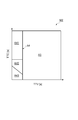
- the collision time prediction unit 33 sets a virtual intersection (cross point) CP that intersects the host vehicle C when the moving body W moves at the virtual speed vp.
- the virtual intersection CP moves due to the time change (t ⁇ t + 1) of the host vehicle C and the moving body W.
- the collision time prediction unit 33 calculates a virtual TTC until the host vehicle C reaches the virtual intersection CP, and a virtual TTV until the mobile body W reaches the virtual intersection CP.
- the collision time prediction unit 33 outputs the virtual TTC information and the virtual TTV information indicating the calculated virtual TTC and virtual TTV to the driving support determination unit 37.
- the map storage unit 35 stores a map (second map) M1 and a map M2.
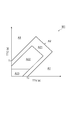
- FIG. 3 is a diagram showing a map. As shown in FIG. 3, in the map M1, the vertical axis is TTC [s] and the horizontal axis is TTV [s], which shows the relative relationship between TTC and TTV.
- the origin is set at the intersection of the host vehicle and the moving body.
- the map M1 As the distance from the origin is increased (as TTC and TTV increase), the map M1 is located at a position away from the intersection.
- a driving assistance unnecessary area (first area) A1 and a driving assistance area (second area) A2 are set.
- the map M1 will be specifically described below.
- the two straight lines that define the driving support area A2 are set as a difference between TTC and TTV (TTC-TTV).
- T 1 and T 2 are set to 1 to 3 seconds, for example.
- the driving assistance area A2 a plurality of driving assistance control contents are set in advance according to the degree of emergency, and an HMI area A21, an intervention control area A22, and an emergency intervention control area A23 are set.
- the HMI area A21 is an area where driving assistance is performed such as warning the driver.
- the intervention control area A22 is set inside the HMI area A21.
- the intervention control area A22 is an area where intervention control such as braking is performed.
- the emergency intervention control area A23 is an area in which emergency braking control for avoiding a collision is performed by performing sudden braking or the like.
- the emergency intervention control area A23 is set near the origin of the map M1, that is, near the intersection of the host vehicle and the moving body.
- the driving support unnecessary area A1 is a portion other than the driving support area A2, and is an area that does not require driving support for avoiding a collision between the host vehicle and the moving body. That is, in the case where it corresponds to the driving assistance unnecessary area A1, when the own vehicle reaches the intersection, the moving body has already passed the intersection, or the moving body is located at a place away from the intersection. Will be.
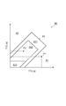
- FIG. 4 is a diagram showing a map.
- the map M2 has a vertical axis of TTC [s] and a horizontal axis of TTV [s], and shows a relative relationship between TTC and TTV.
- the origin is set at the intersection of the host vehicle and the moving body.
- the map M2 as the distance from the origin increases (as TTC and TTV increase), the map M2 is located at a location far from the intersection.
- a driving support unnecessary area A3 and a driving support area A4 are set.
- the driving support area A4 a plurality of driving support control contents are set in advance according to the degree of emergency, and an HMI area A41, an intervention control area A42, and an emergency intervention control area A43 are set.
- the HMI area A41 is an area where driving assistance is performed such as warning the driver.
- the intervention control area A42 is an area for performing intervention control such as braking.
- the emergency intervention control area A43 is an area in which emergency braking control is performed to avoid a collision by performing sudden braking or the like.
- the emergency intervention control area A23 is set near the origin of the map M2, that is, near the intersection between the host vehicle and the moving body.
- the driving support unnecessary area A3 is a part other than the driving support area A4, and is an area that does not require driving support for avoiding a collision between the host vehicle and the moving body.
- driving support areas A2 and A4 and driving support unnecessary areas A1 and A3 may be set based on experimental data or the like, and the driver's driving characteristics (accelerator characteristics, brake characteristics) are learned. By doing so, driving support areas A2 and A4 and driving support unnecessary areas A1 and A3 may be set.
- the driving assistance control amounts may be set in the intervention control areas A22 and A42 and the emergency intervention control areas A23 and A43, respectively.
- the map M2 may be set according to the environment (such as weather) around the host vehicle.
- the maps M1 and M2 stored (stored) in the map storage unit 35 can be rewritten (update of the driving support control unit 39).
- the driving support determination unit 37 is a part that determines whether or not driving support is performed in the host vehicle.
- the driving support determination unit 37 applies TTC and TTV, or virtual TTC and virtual TTV to the map M1 or map M2, and determines whether or not driving support is to be performed in the host vehicle.
- the driving support determination unit 37 applies the TTC information and the TTV information output from the collision time prediction unit 33 to the map M1, and the intersection where the TTC and the TTV intersect is located in which area of the map M1.
- the driving support determination unit 37 determines that the driving support is performed in the own vehicle because it is the driving support area A2 (intervention control area A22).
- the driving support determination unit 37 provides the driving support control unit 39 with support execution information including information indicating any one of the HMI area A21, the intervention control area A22, and the emergency intervention control area A23. Output.
- the driving support determination unit 37 applies the virtual TTC information and the virtual TTV information output from the collision time prediction unit 33 to the map M2, and the intersection where the virtual TTC and the virtual TTV intersect is determined. It is determined which area of the map M2 is located.
- the driving support determination unit 37 provides the driving support control unit 39 with support execution information including information indicating any one of the HMI area A41, the intervention control area A42, and the emergency intervention control area A43. Output.
- the driving support control unit 39 is a part that controls driving support in the host vehicle.
- the driving support control unit 39 controls driving support (intervention control) based on the support execution information.
- the intervention control is, for example, braking control or steering control.
- the driving support control unit 39 outputs a warning instruction signal to the HMI 9 when the support execution information includes information indicating the HMI areas A21 and A41.
- the driving support control unit 39 calculates the control amount of the intervention control.
- the driving support control unit 39 controls braking based on the map M1 or the map M2.
- the amount target acceleration (deceleration acceleration), speed) is calculated.
- the driving support control unit 39 calculates the braking control amount based on the following equation (3) when the control amount is not set in the maps M1 and M2. ⁇ ⁇ TTC + ⁇ ⁇ TTV + ⁇ (3)
- ⁇ and ⁇ are coefficients, and ⁇ is a constant.
- the driving support control unit 39 outputs an intervention control signal including a control amount to the intervention control ECU 11.
- the HMI 9 is a buzzer, HUD (Head Up Display), a navigation system monitor, a meter panel, and the like.
- HMI 9 receives the warning instruction signal output from the ECU 3
- the HMI 9 plays a sound for warning the driver that the moving body exists ahead, or displays a warning text or the like. For example, when the HMI 9 is HUD, a pop-up indicating that a moving body is present on the windshield is displayed.
- the intervention control ECU 11 is an ECU that executes intervention control in the host vehicle.
- the intervention control ECU 11 is composed of a brake ECU, an engine ECU (not shown), and the like.
- FIG. 6 is a flowchart showing the operation of the driving support apparatus.
- the state of the moving body is detected by the moving body detection sensor 5 (step S01). Further, the traveling state of the host vehicle is detected by the vehicle sensor 7 (step S02). Next, the angle determination unit 31 detects a velocity vector of the moving object from the moving object information detected by the moving object detection sensor 5 (step S03). Moreover, based on the vehicle information produced
- an angle A formed by the velocity vector of the moving object and the predicted movement direction of the host vehicle is calculated by the angle determination unit 31 (step S05). Then, the angle determination unit 31 determines whether or not the calculated angle A is greater than or equal to the threshold value B (step S06). If it is determined that the formed angle A is equal to or greater than the threshold value B, the process proceeds to step S07. On the other hand, if it is not determined that the formed angle A is equal to or greater than the threshold value B, the process proceeds to step S16.
- Step S07 TTC and TTV are calculated by the collision time prediction unit 33 based on the moving body information and the vehicle information detected by the moving body detection sensor 5 and the vehicle sensor 7. Then, the TTC and TTV calculated by the collision time prediction unit 33 are applied to the map M1 stored in the map storage unit 35 (step S08), and it is determined whether or not driving support is to be performed in the host vehicle. This is performed in the determination unit 37.
- the driving support determination unit 37 determines whether or not the intersection of TTC and TTV is the HMI area A21, that is, whether or not it is the driving support area A2 (step S09). If it is determined that the area is the HMI area A21, the HMI operation flag is set to “1” (step S10). On the other hand, if it is not determined that the area is the HMI area A21, that is, if it is determined that the area is the driving assistance unnecessary area A1, the process returns to step S01.
- step S11 it is determined in the driving support determination unit 37 whether or not it is the intervention control area A22 (step S11). If it is determined that it is the intervention control area A22, the driving support control unit 39 calculates the control amount of the intervention control based on, for example, the map M1 (step S12). On the other hand, if it is not determined that it is the intervention control area A22, the process proceeds to step S15.
- step S13 it is determined in the driving support determination unit 37 whether or not it is the emergency intervention control area A23 (step S13). If it is determined that it is the emergency intervention control area A23, the driving assistance control unit 39 calculates a control amount for emergency avoidance (step S14). On the other hand, if the emergency intervention control area A23 is not determined, the process proceeds to step S15.
- step S15 driving support is implemented. Specifically, a warning is given to the driver by the HMI 9. In addition, intervention control is performed by the intervention control ECU 11 together with a warning by the HMI 9.
- step S16 the virtual moving speed (virtual speed) of the moving body is set by the collision time prediction unit 33. Then, based on the virtual moving speed of the moving body, the virtual TTC and the virtual TTV are calculated by the collision time prediction unit 33 (step S17). Then, the virtual TTC and the virtual TTV calculated by the collision time prediction unit 33 are applied to the map M2 stored in the map storage unit 35 (step S18), and it is determined whether or not driving assistance is to be performed in the host vehicle. This is performed in the driving support determination unit 37.
- the driving support determination unit 37 determines whether or not the intersection of the virtual TTC and the virtual TTV is the HMI area A41, that is, the driving support area A4 (step S19). If it is determined that the area is the HMI area A41, the HMI operation flag is set to “1” (step S20). On the other hand, when it is not determined that the area is the HMI area A41, that is, when it is determined that the area is the driving support unnecessary area A3, the process returns to the step S01.
- step S21 it is determined in the driving support determination part 37 whether it is intervention control area A42 (step S21). If it is determined that it is the intervention control area A42, the driving support control unit 39 calculates the control amount of the intervention control based on, for example, the map M2 (step S22). On the other hand, if it is not determined that it is the intervention control area A42, the process proceeds to step S15.
- step S23 it is determined in the driving support determination part 37 whether it is emergency intervention control area A43 (step S23).
- the driving assistance control unit 39 calculates a control amount for emergency avoidance (step S24).
- step S24 the process proceeds to step S15.
- the intersection point CP where the host vehicle and the moving body intersect is predicted, the virtual TTC until the host vehicle reaches the intersection point, and the virtually set virtual speed vp.
- the virtual TTV until the moving body reaches the intersection CP is obtained.
- driving assistance can be implemented by predicting the crossing of the moving body, driving assistance can also be implemented for a moving body that has not actually crossed. Accordingly, it is possible to cope with a case where the moving body suddenly changes its direction in the transverse direction when passing the side of the moving body. Therefore, the reliability can be improved.
- the angle A formed by the predicted movement direction of the host vehicle and the direction of the moving body is calculated. If the formed angle A is equal to or greater than the threshold value B, whether or not driving assistance is performed using the map M1. If the angle A formed is smaller than the threshold value B, it is determined whether or not driving assistance is to be performed using the map M2. In this way, by changing the maps M1 and M2 used according to the formed angle A, it is possible to implement driving support optimal for the positional relationship between the host vehicle and the moving body.
- the maps M1 and M2 include driving support unnecessary areas A1 and A3 and driving support areas A2 and A4.
- the driving support areas A2 and A4 include HMI areas A21 and A41 and an intervention control area A22. , A42 and emergency intervention control areas A23, A43 are set.
- the present invention is not limited to the above embodiment.
- the map M1 and the map 2 are used separately, but the map M1 and the map M2 may be one map.
- the warning by the HIM 9 is also performed at the same time.
- the warning by the HIM 9 may not be performed.
Landscapes
- Engineering & Computer Science (AREA)
- Transportation (AREA)
- Mechanical Engineering (AREA)
- Automation & Control Theory (AREA)
- Physics & Mathematics (AREA)
- General Physics & Mathematics (AREA)
- Chemical & Material Sciences (AREA)
- Combustion & Propulsion (AREA)
- Radar, Positioning & Navigation (AREA)
- Remote Sensing (AREA)
- Traffic Control Systems (AREA)
Abstract
Description
TTC=x/(V-vx) …(1)
TTV=y/vy …(2)
上記式(1),(2)において、V:自車両の速度、x,y:移動体の相対位置、vx,vy:移動体の速度である。衝突時間予測部33は、算出したTTC及びTTVを示すTTC情報及びTTV情報を運転支援判断部37に出力する。
α×TTC+β×TTV+γ …(3)
ここで、α,βは係数であり、γは定数である。α,β,γは、実験値などに基づいて設定されている。また、操舵の制御量は、実験値や所定の式などに基づいて算出する。運転支援制御部39は、制御量を含む介入制御信号を介入制御ECU11に出力する。
Claims (6)
- 自車両と移動体との衝突を回避する運転支援を実施する運転支援装置であって、
前記自車両の進行方向と当該進行方向に交差する方向とにおいて前記自車両と前記移動体とが交差する交差地点を予測し、当該交差地点に前記自車両が到達するまでの第1時間と、仮想的に設定した仮想速度により前記移動体が進行方向に交差する方向に移動したきに前記交差地点に前記移動体が到達するまでの第2時間とをそれぞれ求め、第1時間と第2時間との相対関係に基づいて、前記自車両における運転支援を行うことを特徴とする運転支援装置。 - 前記自車両が進行方向において前記交差地点に到達するまでの前記第1時間を予測する第1時間予測手段と、
前記移動体が前記進行方向に交差する方向において前記仮想速度により前記交差地点に到達するまでの前記第2時間を予測する第2時間予測手段と、
前記第1及び第2時間予測手段によって予測された前記第1及び第2時間を予め設定されたマップに適用して、前記自車両において運転支援を実施するか否かの判断を行う運転支援判断手段と、
前記運転支援判断手段により前記自車両において運転支援を実施すると判断された場合に、前記自車両における運転支援を制御する運転支援制御手段と、
を備える、請求項1記載の運転支援装置。 - 前記自車両の走行状態を検出する走行状態検出手段と、
前記移動体の状態を検出する移動体状態検出手段と、
前記走行状態検出手段により検出された前記自車両の状態に基づいて前記自車両の移動予測方向を算出する移動予測方向算出手段と、
前記移動体状態検出手段によって検出された前記移動体の状態から前記移動体の速度ベクトルを検出するベクトル検出手段と、
前記自車両の前記移動予測方向と前記移動体の向きとが成す角度を算出し、当該成す角度が所定角度以上であるか否かを判定する角度判定手段と、
を備え、
前記運転支援判断手段は、前記角度判定手段によって前記所定角度以上であると判定されなかった場合には前記マップを用い、前記角度判定手段によって前記所定角度以上であると判定された場合には、前記マップにおいて、検出された前記移動体の速度により当該移動体が進行方向に交差する方向に移動したときに前記交差地点に前記移動体が到達するまでの時間を第2時間とした第2マップを用いる、請求項2記載の運転支援装置。 - 前記マップ及び前記第2マップは、前記第1時間が縦軸で且つ前記第2時間が横軸として設定されていると共に、運転支援が不要であると判断される第1領域と、運転支援が必要であると判断される第2領域とが設定されており、
前記運転支援判断手段は、前記第1時間と前記第2時間とが交わる点が前記第2領域に存在する場合に、前記自車両において運転支援を実施すると判断する、請求項3記載の運転支援装置。 - 前記マップ及び前記第2マップは、一つのマップに構成されている、請求項3又は4記載の運転支援装置。
- 自車両と移動体との衝突を回避する運転支援方法であって、
前記自車両の進行方向と当該進行方向に交差する方向とにおいて前記自車両と前記移動体とが交差する交差地点を予測し、当該交差地点に前記自車両が到達するまでの第1時間と、仮想的に設定した仮想速度により前記移動体が進行方向に交差する方向に移動したきに前記交差地点に前記移動体が到達するまでの第2時間とをそれぞれ求め、第1時間と第2時間との相対関係に基づいて、自車両における運転支援を行うことを特徴とする運転支援方法。
Priority Applications (5)
| Application Number | Priority Date | Filing Date | Title |
|---|---|---|---|
| JP2013530891A JP5641146B2 (ja) | 2011-08-26 | 2011-08-26 | 運転支援装置及び運転支援方法 |
| CN201180073022.5A CN103765487B (zh) | 2011-08-26 | 2011-08-26 | 驾驶辅助装置以及驾驶辅助方法 |
| EP11871550.7A EP2750118B1 (en) | 2011-08-26 | 2011-08-26 | Driving support apparatus and driving support method |
| US14/240,808 US9196163B2 (en) | 2011-08-26 | 2011-08-26 | Driving support apparatus and driving support method |
| PCT/JP2011/069329 WO2013030906A1 (ja) | 2011-08-26 | 2011-08-26 | 運転支援装置及び運転支援方法 |
Applications Claiming Priority (1)
| Application Number | Priority Date | Filing Date | Title |
|---|---|---|---|
| PCT/JP2011/069329 WO2013030906A1 (ja) | 2011-08-26 | 2011-08-26 | 運転支援装置及び運転支援方法 |
Publications (1)
| Publication Number | Publication Date |
|---|---|
| WO2013030906A1 true WO2013030906A1 (ja) | 2013-03-07 |
Family
ID=47755461
Family Applications (1)
| Application Number | Title | Priority Date | Filing Date |
|---|---|---|---|
| PCT/JP2011/069329 Ceased WO2013030906A1 (ja) | 2011-08-26 | 2011-08-26 | 運転支援装置及び運転支援方法 |
Country Status (5)
| Country | Link |
|---|---|
| US (1) | US9196163B2 (ja) |
| EP (1) | EP2750118B1 (ja) |
| JP (1) | JP5641146B2 (ja) |
| CN (1) | CN103765487B (ja) |
| WO (1) | WO2013030906A1 (ja) |
Cited By (3)
| Publication number | Priority date | Publication date | Assignee | Title |
|---|---|---|---|---|
| CN104851320A (zh) * | 2015-04-28 | 2015-08-19 | 奇瑞汽车股份有限公司 | 一种提示驾驶员的方法和装置 |
| CN104973055A (zh) * | 2014-04-14 | 2015-10-14 | 本田技研工业株式会社 | 碰撞可能性判定装置、驾驶辅助装置、碰撞可能性判定方法及碰撞可能性判定程序 |
| JP2017105249A (ja) * | 2015-12-07 | 2017-06-15 | 株式会社Subaru | 車両の運転支援制御装置 |
Families Citing this family (23)
| Publication number | Priority date | Publication date | Assignee | Title |
|---|---|---|---|---|
| JP6049542B2 (ja) * | 2013-05-31 | 2016-12-21 | 日立オートモティブシステムズ株式会社 | 車両制御システム |
| CN104050837A (zh) * | 2014-06-10 | 2014-09-17 | 奇瑞汽车股份有限公司 | 一种行车安全提示方法和装置 |
| KR101628503B1 (ko) * | 2014-10-27 | 2016-06-08 | 현대자동차주식회사 | 운전자 보조장치 및 그 작동 방법 |
| JP6462328B2 (ja) * | 2014-11-18 | 2019-01-30 | 日立オートモティブシステムズ株式会社 | 走行制御システム |
| CN104376735B (zh) * | 2014-11-21 | 2016-10-12 | 中国科学院合肥物质科学研究院 | 一种盲区路口车辆行驶安全预警系统及其预警方法 |
| JP6304223B2 (ja) * | 2015-12-10 | 2018-04-04 | トヨタ自動車株式会社 | 運転支援装置 |
| JP2017117344A (ja) * | 2015-12-25 | 2017-06-29 | 株式会社デンソー | 走行支援装置 |
| JP6569523B2 (ja) * | 2015-12-25 | 2019-09-04 | 株式会社デンソー | 走行支援装置 |
| JP2018018389A (ja) * | 2016-07-29 | 2018-02-01 | パナソニックIpマネジメント株式会社 | 自動運転車輌の制御装置、及び制御プログラム |
| JP6609237B2 (ja) * | 2016-11-17 | 2019-11-20 | 株式会社デンソー | 衝突判定装置、及び衝突判定方法 |
| US10474163B2 (en) * | 2016-11-24 | 2019-11-12 | Lg Electronics Inc. | Vehicle control device mounted on vehicle and method for controlling the vehicle |
| KR102014259B1 (ko) * | 2016-11-24 | 2019-08-26 | 엘지전자 주식회사 | 차량에 구비된 차량 제어 장치 및 차량의 제어방법 |
| KR102663017B1 (ko) * | 2016-11-24 | 2024-05-07 | 현대자동차주식회사 | 차량 및 그 제어방법 |
| US10611370B2 (en) * | 2017-02-09 | 2020-04-07 | Panasonic Intellectual Property Corporation Of America | Information processing apparatus, information processing method, and non-transitory recording medium |
| EP3413083B1 (en) * | 2017-06-09 | 2020-03-11 | Veoneer Sweden AB | A vehicle system for detection of oncoming vehicles |
| EP3413082B1 (en) * | 2017-06-09 | 2020-01-01 | Veoneer Sweden AB | A vehicle system for detection of oncoming vehicles |
| KR102486179B1 (ko) * | 2018-02-20 | 2023-01-10 | 현대자동차주식회사 | 차량 및 그 제어 방법 |
| JP7085371B2 (ja) * | 2018-03-15 | 2022-06-16 | 本田技研工業株式会社 | 車両制御装置、車両制御方法、およびプログラム |
| WO2020096077A1 (ko) * | 2018-11-06 | 2020-05-14 | 엘지전자 주식회사 | 차량용 전자 장치, 차량용 전자 장치의 동작 방법 및 시스템 |
| US11332132B2 (en) * | 2019-08-30 | 2022-05-17 | Argo AI, LLC | Method of handling occlusions at intersections in operation of autonomous vehicle |
| US10971005B1 (en) * | 2019-12-26 | 2021-04-06 | Continental Automotive Systems, Inc. | Determining I2X traffic-participant criticality |
| US20210101620A1 (en) * | 2020-12-17 | 2021-04-08 | Intel Corporation | Systems, methods, and devices for generating and using safety threat maps |
| TWI796846B (zh) * | 2021-11-23 | 2023-03-21 | 財團法人工業技術研究院 | 基於物件互動關係之路徑預測方法及電子裝置 |
Citations (5)
| Publication number | Priority date | Publication date | Assignee | Title |
|---|---|---|---|---|
| JP2004164315A (ja) * | 2002-11-13 | 2004-06-10 | Toyota Motor Corp | 車両用衝突警報システム |
| JP2006256493A (ja) * | 2005-03-17 | 2006-09-28 | Advics:Kk | 車両用走行支援装置 |
| JP2007257338A (ja) * | 2006-03-23 | 2007-10-04 | Toyota Central Res & Dev Lab Inc | 潜在危険度推定装置 |
| JP2009053925A (ja) * | 2007-08-27 | 2009-03-12 | Toyota Motor Corp | 行動予測装置 |
| JP2010257298A (ja) | 2009-04-27 | 2010-11-11 | Honda Motor Co Ltd | 車両の走行安全装置 |
Family Cites Families (6)
| Publication number | Priority date | Publication date | Assignee | Title |
|---|---|---|---|---|
| JP3653954B2 (ja) * | 1997-10-23 | 2005-06-02 | トヨタ自動車株式会社 | 移動体交通制御システムの移動体装置、移動体交通制御システムの管制局、移動体交通制御システム |
| US7124027B1 (en) * | 2002-07-11 | 2006-10-17 | Yazaki North America, Inc. | Vehicular collision avoidance system |
| JP2004302621A (ja) | 2003-03-28 | 2004-10-28 | Calsonic Kansei Corp | 車両衝突防止装置 |
| US7729857B2 (en) * | 2005-08-18 | 2010-06-01 | Gm Global Technology Operations, Inc. | System for and method of detecting a collision and predicting a vehicle path |
| JP2010188981A (ja) * | 2009-02-20 | 2010-09-02 | Fuji Heavy Ind Ltd | 車両の運転支援装置 |
| US8577550B2 (en) * | 2009-10-05 | 2013-11-05 | Ford Global Technologies, Llc | System for vehicle control to mitigate intersection collisions and method of using the same |
-
2011
- 2011-08-26 JP JP2013530891A patent/JP5641146B2/ja not_active Expired - Fee Related
- 2011-08-26 EP EP11871550.7A patent/EP2750118B1/en active Active
- 2011-08-26 US US14/240,808 patent/US9196163B2/en not_active Expired - Fee Related
- 2011-08-26 WO PCT/JP2011/069329 patent/WO2013030906A1/ja not_active Ceased
- 2011-08-26 CN CN201180073022.5A patent/CN103765487B/zh not_active Expired - Fee Related
Patent Citations (5)
| Publication number | Priority date | Publication date | Assignee | Title |
|---|---|---|---|---|
| JP2004164315A (ja) * | 2002-11-13 | 2004-06-10 | Toyota Motor Corp | 車両用衝突警報システム |
| JP2006256493A (ja) * | 2005-03-17 | 2006-09-28 | Advics:Kk | 車両用走行支援装置 |
| JP2007257338A (ja) * | 2006-03-23 | 2007-10-04 | Toyota Central Res & Dev Lab Inc | 潜在危険度推定装置 |
| JP2009053925A (ja) * | 2007-08-27 | 2009-03-12 | Toyota Motor Corp | 行動予測装置 |
| JP2010257298A (ja) | 2009-04-27 | 2010-11-11 | Honda Motor Co Ltd | 車両の走行安全装置 |
Non-Patent Citations (1)
| Title |
|---|
| See also references of EP2750118A4 |
Cited By (4)
| Publication number | Priority date | Publication date | Assignee | Title |
|---|---|---|---|---|
| CN104973055A (zh) * | 2014-04-14 | 2015-10-14 | 本田技研工业株式会社 | 碰撞可能性判定装置、驾驶辅助装置、碰撞可能性判定方法及碰撞可能性判定程序 |
| CN104973055B (zh) * | 2014-04-14 | 2017-12-29 | 本田技研工业株式会社 | 碰撞可能性判定装置、驾驶辅助装置、碰撞可能性判定方法及碰撞可能性判定程序 |
| CN104851320A (zh) * | 2015-04-28 | 2015-08-19 | 奇瑞汽车股份有限公司 | 一种提示驾驶员的方法和装置 |
| JP2017105249A (ja) * | 2015-12-07 | 2017-06-15 | 株式会社Subaru | 車両の運転支援制御装置 |
Also Published As
| Publication number | Publication date |
|---|---|
| CN103765487A (zh) | 2014-04-30 |
| JP5641146B2 (ja) | 2014-12-17 |
| EP2750118A4 (en) | 2016-04-06 |
| CN103765487B (zh) | 2016-03-30 |
| US9196163B2 (en) | 2015-11-24 |
| EP2750118A1 (en) | 2014-07-02 |
| EP2750118B1 (en) | 2020-01-01 |
| JPWO2013030906A1 (ja) | 2015-03-23 |
| US20140288816A1 (en) | 2014-09-25 |
Similar Documents
| Publication | Publication Date | Title |
|---|---|---|
| JP5641146B2 (ja) | 運転支援装置及び運転支援方法 | |
| JP5664790B2 (ja) | 運転支援装置及び運転支援方法 | |
| JP5668862B2 (ja) | 運転支援装置及び運転支援方法 | |
| JP6318864B2 (ja) | 運転支援装置 | |
| US9058247B2 (en) | Risk potential calculation apparatus | |
| JP6036839B2 (ja) | 運転支援装置及び運転支援方法 | |
| JP5846106B2 (ja) | 運転支援装置及び運転支援方法 | |
| JP2018090006A (ja) | 運転支援装置 | |
| JP2008003880A (ja) | 車両周辺監視システム、車両周辺監視プログラム、車両周辺監視システムの構築方法およびサーバ | |
| JP2013246768A (ja) | 運転支援装置 | |
| JP5733273B2 (ja) | 運転支援装置及び運転支援方法 | |
| JP2013186626A (ja) | 運転支援装置及び運転支援方法 | |
| JP5915386B2 (ja) | 運転支援装置及び運転支援方法 | |
| JP2013149077A (ja) | 運転支援装置及び運転支援方法 | |
| JP2013156688A (ja) | 運転支援装置及び運転支援方法 | |
| WO2013132621A1 (ja) | 運転支援装置及び運転支援方法 | |
| JP2013156687A (ja) | 運転支援装置及び運転支援方法 | |
| JP2013161232A (ja) | 運転支援装置及び運転支援方法 | |
| JP2011113239A (ja) | 車両の衝突を回避するための装置 | |
| JP2013246767A (ja) | 運転支援装置 | |
| JP2014148291A (ja) | 運転支援装置及び運転支援方法 |
Legal Events
| Date | Code | Title | Description |
|---|---|---|---|
| WWE | Wipo information: entry into national phase |
Ref document number: 201180073022.5 Country of ref document: CN |
|
| 121 | Ep: the epo has been informed by wipo that ep was designated in this application |
Ref document number: 11871550 Country of ref document: EP Kind code of ref document: A1 |
|
| ENP | Entry into the national phase |
Ref document number: 2013530891 Country of ref document: JP Kind code of ref document: A |
|
| WWE | Wipo information: entry into national phase |
Ref document number: 14240808 Country of ref document: US |
|
| NENP | Non-entry into the national phase |
Ref country code: DE |