WO2013031073A1 - 充電システム及び充電装置並びに充電方法 - Google Patents
充電システム及び充電装置並びに充電方法 Download PDFInfo
- Publication number
- WO2013031073A1 WO2013031073A1 PCT/JP2012/004238 JP2012004238W WO2013031073A1 WO 2013031073 A1 WO2013031073 A1 WO 2013031073A1 JP 2012004238 W JP2012004238 W JP 2012004238W WO 2013031073 A1 WO2013031073 A1 WO 2013031073A1
- Authority
- WO
- WIPO (PCT)
- Prior art keywords
- charging
- current
- power
- command
- charging device
- Prior art date
- Legal status (The legal status is an assumption and is not a legal conclusion. Google has not performed a legal analysis and makes no representation as to the accuracy of the status listed.)
- Ceased
Links
Images


Classifications
-
- B—PERFORMING OPERATIONS; TRANSPORTING
- B60—VEHICLES IN GENERAL
- B60L—PROPULSION OF ELECTRICALLY-PROPELLED VEHICLES; SUPPLYING ELECTRIC POWER FOR AUXILIARY EQUIPMENT OF ELECTRICALLY-PROPELLED VEHICLES; ELECTRODYNAMIC BRAKE SYSTEMS FOR VEHICLES IN GENERAL; MAGNETIC SUSPENSION OR LEVITATION FOR VEHICLES; MONITORING OPERATING VARIABLES OF ELECTRICALLY-PROPELLED VEHICLES; ELECTRIC SAFETY DEVICES FOR ELECTRICALLY-PROPELLED VEHICLES
- B60L53/00—Methods of charging batteries, specially adapted for electric vehicles; Charging stations or on-board charging equipment therefor; Exchange of energy storage elements in electric vehicles
- B60L53/30—Constructional details of charging stations
- B60L53/305—Communication interfaces
-
- B—PERFORMING OPERATIONS; TRANSPORTING
- B60—VEHICLES IN GENERAL
- B60L—PROPULSION OF ELECTRICALLY-PROPELLED VEHICLES; SUPPLYING ELECTRIC POWER FOR AUXILIARY EQUIPMENT OF ELECTRICALLY-PROPELLED VEHICLES; ELECTRODYNAMIC BRAKE SYSTEMS FOR VEHICLES IN GENERAL; MAGNETIC SUSPENSION OR LEVITATION FOR VEHICLES; MONITORING OPERATING VARIABLES OF ELECTRICALLY-PROPELLED VEHICLES; ELECTRIC SAFETY DEVICES FOR ELECTRICALLY-PROPELLED VEHICLES
- B60L53/00—Methods of charging batteries, specially adapted for electric vehicles; Charging stations or on-board charging equipment therefor; Exchange of energy storage elements in electric vehicles
- B60L53/60—Monitoring or controlling charging stations
- B60L53/64—Optimising energy costs, e.g. responding to electricity rates
-
- B—PERFORMING OPERATIONS; TRANSPORTING
- B60—VEHICLES IN GENERAL
- B60L—PROPULSION OF ELECTRICALLY-PROPELLED VEHICLES; SUPPLYING ELECTRIC POWER FOR AUXILIARY EQUIPMENT OF ELECTRICALLY-PROPELLED VEHICLES; ELECTRODYNAMIC BRAKE SYSTEMS FOR VEHICLES IN GENERAL; MAGNETIC SUSPENSION OR LEVITATION FOR VEHICLES; MONITORING OPERATING VARIABLES OF ELECTRICALLY-PROPELLED VEHICLES; ELECTRIC SAFETY DEVICES FOR ELECTRICALLY-PROPELLED VEHICLES
- B60L53/00—Methods of charging batteries, specially adapted for electric vehicles; Charging stations or on-board charging equipment therefor; Exchange of energy storage elements in electric vehicles
- B60L53/60—Monitoring or controlling charging stations
- B60L53/65—Monitoring or controlling charging stations involving identification of vehicles or their battery types
-
- B—PERFORMING OPERATIONS; TRANSPORTING
- B60—VEHICLES IN GENERAL
- B60L—PROPULSION OF ELECTRICALLY-PROPELLED VEHICLES; SUPPLYING ELECTRIC POWER FOR AUXILIARY EQUIPMENT OF ELECTRICALLY-PROPELLED VEHICLES; ELECTRODYNAMIC BRAKE SYSTEMS FOR VEHICLES IN GENERAL; MAGNETIC SUSPENSION OR LEVITATION FOR VEHICLES; MONITORING OPERATING VARIABLES OF ELECTRICALLY-PROPELLED VEHICLES; ELECTRIC SAFETY DEVICES FOR ELECTRICALLY-PROPELLED VEHICLES
- B60L53/00—Methods of charging batteries, specially adapted for electric vehicles; Charging stations or on-board charging equipment therefor; Exchange of energy storage elements in electric vehicles
- B60L53/60—Monitoring or controlling charging stations
- B60L53/66—Data transfer between charging stations and vehicles
- B60L53/665—Methods related to measuring, billing or payment
-
- H—ELECTRICITY
- H01—ELECTRIC ELEMENTS
- H01M—PROCESSES OR MEANS, e.g. BATTERIES, FOR THE DIRECT CONVERSION OF CHEMICAL ENERGY INTO ELECTRICAL ENERGY
- H01M10/00—Secondary cells; Manufacture thereof
- H01M10/42—Methods or arrangements for servicing or maintenance of secondary cells or secondary half-cells
- H01M10/44—Methods for charging or discharging
-
- H—ELECTRICITY
- H02—GENERATION; CONVERSION OR DISTRIBUTION OF ELECTRIC POWER
- H02J—ELECTRIC POWER NETWORKS; CIRCUIT ARRANGEMENTS OR SYSTEMS FOR SUPPLYING OR DISTRIBUTING ELECTRIC POWER; SYSTEMS FOR STORING ELECTRIC ENERGY
- H02J3/00—Circuit arrangements for AC mains or AC distribution networks
- H02J3/28—Arrangements for balancing of the load in networks by storage of energy
- H02J3/32—Arrangements for balancing of the load in networks by storage of energy using batteries or super capacitors with converting means
- H02J3/322—Arrangements for balancing of the load in networks by storage of energy using batteries or super capacitors with converting means the battery being on-board an electric or hybrid vehicle, e.g. vehicle to grid arrangements [V2G], power aggregation, use of the battery for network load balancing, coordinated or cooperative battery charging
-
- H—ELECTRICITY
- H02—GENERATION; CONVERSION OR DISTRIBUTION OF ELECTRIC POWER
- H02J—ELECTRIC POWER NETWORKS; CIRCUIT ARRANGEMENTS OR SYSTEMS FOR SUPPLYING OR DISTRIBUTING ELECTRIC POWER; SYSTEMS FOR STORING ELECTRIC ENERGY
- H02J7/00—Circuit arrangements for charging or discharging batteries or for supplying loads from batteries
- H02J7/02—Circuit arrangements for charging or discharging batteries or for supplying loads from batteries for charging batteries from AC mains by converters
- H02J7/04—Regulation of charging current or voltage
-
- H—ELECTRICITY
- H02—GENERATION; CONVERSION OR DISTRIBUTION OF ELECTRIC POWER
- H02J—ELECTRIC POWER NETWORKS; CIRCUIT ARRANGEMENTS OR SYSTEMS FOR SUPPLYING OR DISTRIBUTING ELECTRIC POWER; SYSTEMS FOR STORING ELECTRIC ENERGY
- H02J7/00—Circuit arrangements for charging or discharging batteries or for supplying loads from batteries
- H02J7/90—Regulation of charging or discharging current or voltage
-
- B—PERFORMING OPERATIONS; TRANSPORTING
- B60—VEHICLES IN GENERAL
- B60L—PROPULSION OF ELECTRICALLY-PROPELLED VEHICLES; SUPPLYING ELECTRIC POWER FOR AUXILIARY EQUIPMENT OF ELECTRICALLY-PROPELLED VEHICLES; ELECTRODYNAMIC BRAKE SYSTEMS FOR VEHICLES IN GENERAL; MAGNETIC SUSPENSION OR LEVITATION FOR VEHICLES; MONITORING OPERATING VARIABLES OF ELECTRICALLY-PROPELLED VEHICLES; ELECTRIC SAFETY DEVICES FOR ELECTRICALLY-PROPELLED VEHICLES
- B60L2210/00—Converter types
- B60L2210/30—AC to DC converters
-
- B—PERFORMING OPERATIONS; TRANSPORTING
- B60—VEHICLES IN GENERAL
- B60L—PROPULSION OF ELECTRICALLY-PROPELLED VEHICLES; SUPPLYING ELECTRIC POWER FOR AUXILIARY EQUIPMENT OF ELECTRICALLY-PROPELLED VEHICLES; ELECTRODYNAMIC BRAKE SYSTEMS FOR VEHICLES IN GENERAL; MAGNETIC SUSPENSION OR LEVITATION FOR VEHICLES; MONITORING OPERATING VARIABLES OF ELECTRICALLY-PROPELLED VEHICLES; ELECTRIC SAFETY DEVICES FOR ELECTRICALLY-PROPELLED VEHICLES
- B60L2240/00—Control parameters of input or output; Target parameters
- B60L2240/40—Drive Train control parameters
- B60L2240/54—Drive Train control parameters related to batteries
- B60L2240/547—Voltage
-
- B—PERFORMING OPERATIONS; TRANSPORTING
- B60—VEHICLES IN GENERAL
- B60L—PROPULSION OF ELECTRICALLY-PROPELLED VEHICLES; SUPPLYING ELECTRIC POWER FOR AUXILIARY EQUIPMENT OF ELECTRICALLY-PROPELLED VEHICLES; ELECTRODYNAMIC BRAKE SYSTEMS FOR VEHICLES IN GENERAL; MAGNETIC SUSPENSION OR LEVITATION FOR VEHICLES; MONITORING OPERATING VARIABLES OF ELECTRICALLY-PROPELLED VEHICLES; ELECTRIC SAFETY DEVICES FOR ELECTRICALLY-PROPELLED VEHICLES
- B60L2240/00—Control parameters of input or output; Target parameters
- B60L2240/40—Drive Train control parameters
- B60L2240/54—Drive Train control parameters related to batteries
- B60L2240/549—Current
-
- H—ELECTRICITY
- H02—GENERATION; CONVERSION OR DISTRIBUTION OF ELECTRIC POWER
- H02J—ELECTRIC POWER NETWORKS; CIRCUIT ARRANGEMENTS OR SYSTEMS FOR SUPPLYING OR DISTRIBUTING ELECTRIC POWER; SYSTEMS FOR STORING ELECTRIC ENERGY
- H02J2105/00—Networks for supplying or distributing electric power characterised by their spatial reach or by the load
- H02J2105/30—Networks for supplying or distributing electric power characterised by their spatial reach or by the load the load networks being external to vehicles, i.e. exchanging power with vehicles
- H02J2105/33—Networks for supplying or distributing electric power characterised by their spatial reach or by the load the load networks being external to vehicles, i.e. exchanging power with vehicles exchanging power with road vehicles
- H02J2105/37—Networks for supplying or distributing electric power characterised by their spatial reach or by the load the load networks being external to vehicles, i.e. exchanging power with vehicles exchanging power with road vehicles exchanging power with electric vehicles [EV] or with hybrid electric vehicles [HEV]
-
- Y—GENERAL TAGGING OF NEW TECHNOLOGICAL DEVELOPMENTS; GENERAL TAGGING OF CROSS-SECTIONAL TECHNOLOGIES SPANNING OVER SEVERAL SECTIONS OF THE IPC; TECHNICAL SUBJECTS COVERED BY FORMER USPC CROSS-REFERENCE ART COLLECTIONS [XRACs] AND DIGESTS
- Y02—TECHNOLOGIES OR APPLICATIONS FOR MITIGATION OR ADAPTATION AGAINST CLIMATE CHANGE
- Y02E—REDUCTION OF GREENHOUSE GAS [GHG] EMISSIONS, RELATED TO ENERGY GENERATION, TRANSMISSION OR DISTRIBUTION
- Y02E60/00—Enabling technologies; Technologies with a potential or indirect contribution to GHG emissions mitigation
- Y02E60/10—Energy storage using batteries
-
- Y—GENERAL TAGGING OF NEW TECHNOLOGICAL DEVELOPMENTS; GENERAL TAGGING OF CROSS-SECTIONAL TECHNOLOGIES SPANNING OVER SEVERAL SECTIONS OF THE IPC; TECHNICAL SUBJECTS COVERED BY FORMER USPC CROSS-REFERENCE ART COLLECTIONS [XRACs] AND DIGESTS
- Y02—TECHNOLOGIES OR APPLICATIONS FOR MITIGATION OR ADAPTATION AGAINST CLIMATE CHANGE
- Y02T—CLIMATE CHANGE MITIGATION TECHNOLOGIES RELATED TO TRANSPORTATION
- Y02T10/00—Road transport of goods or passengers
- Y02T10/60—Other road transportation technologies with climate change mitigation effect
- Y02T10/70—Energy storage systems for electromobility, e.g. batteries
-
- Y—GENERAL TAGGING OF NEW TECHNOLOGICAL DEVELOPMENTS; GENERAL TAGGING OF CROSS-SECTIONAL TECHNOLOGIES SPANNING OVER SEVERAL SECTIONS OF THE IPC; TECHNICAL SUBJECTS COVERED BY FORMER USPC CROSS-REFERENCE ART COLLECTIONS [XRACs] AND DIGESTS
- Y02—TECHNOLOGIES OR APPLICATIONS FOR MITIGATION OR ADAPTATION AGAINST CLIMATE CHANGE
- Y02T—CLIMATE CHANGE MITIGATION TECHNOLOGIES RELATED TO TRANSPORTATION
- Y02T10/00—Road transport of goods or passengers
- Y02T10/60—Other road transportation technologies with climate change mitigation effect
- Y02T10/7072—Electromobility specific charging systems or methods for batteries, ultracapacitors, supercapacitors or double-layer capacitors
-
- Y—GENERAL TAGGING OF NEW TECHNOLOGICAL DEVELOPMENTS; GENERAL TAGGING OF CROSS-SECTIONAL TECHNOLOGIES SPANNING OVER SEVERAL SECTIONS OF THE IPC; TECHNICAL SUBJECTS COVERED BY FORMER USPC CROSS-REFERENCE ART COLLECTIONS [XRACs] AND DIGESTS
- Y02—TECHNOLOGIES OR APPLICATIONS FOR MITIGATION OR ADAPTATION AGAINST CLIMATE CHANGE
- Y02T—CLIMATE CHANGE MITIGATION TECHNOLOGIES RELATED TO TRANSPORTATION
- Y02T10/00—Road transport of goods or passengers
- Y02T10/60—Other road transportation technologies with climate change mitigation effect
- Y02T10/72—Electric energy management in electromobility
-
- Y—GENERAL TAGGING OF NEW TECHNOLOGICAL DEVELOPMENTS; GENERAL TAGGING OF CROSS-SECTIONAL TECHNOLOGIES SPANNING OVER SEVERAL SECTIONS OF THE IPC; TECHNICAL SUBJECTS COVERED BY FORMER USPC CROSS-REFERENCE ART COLLECTIONS [XRACs] AND DIGESTS
- Y02—TECHNOLOGIES OR APPLICATIONS FOR MITIGATION OR ADAPTATION AGAINST CLIMATE CHANGE
- Y02T—CLIMATE CHANGE MITIGATION TECHNOLOGIES RELATED TO TRANSPORTATION
- Y02T90/00—Enabling technologies or technologies with a potential or indirect contribution to GHG emissions mitigation
- Y02T90/10—Technologies relating to charging of electric vehicles
- Y02T90/12—Electric charging stations
-
- Y—GENERAL TAGGING OF NEW TECHNOLOGICAL DEVELOPMENTS; GENERAL TAGGING OF CROSS-SECTIONAL TECHNOLOGIES SPANNING OVER SEVERAL SECTIONS OF THE IPC; TECHNICAL SUBJECTS COVERED BY FORMER USPC CROSS-REFERENCE ART COLLECTIONS [XRACs] AND DIGESTS
- Y02—TECHNOLOGIES OR APPLICATIONS FOR MITIGATION OR ADAPTATION AGAINST CLIMATE CHANGE
- Y02T—CLIMATE CHANGE MITIGATION TECHNOLOGIES RELATED TO TRANSPORTATION
- Y02T90/00—Enabling technologies or technologies with a potential or indirect contribution to GHG emissions mitigation
- Y02T90/10—Technologies relating to charging of electric vehicles
- Y02T90/14—Plug-in electric vehicles
-
- Y—GENERAL TAGGING OF NEW TECHNOLOGICAL DEVELOPMENTS; GENERAL TAGGING OF CROSS-SECTIONAL TECHNOLOGIES SPANNING OVER SEVERAL SECTIONS OF THE IPC; TECHNICAL SUBJECTS COVERED BY FORMER USPC CROSS-REFERENCE ART COLLECTIONS [XRACs] AND DIGESTS
- Y02—TECHNOLOGIES OR APPLICATIONS FOR MITIGATION OR ADAPTATION AGAINST CLIMATE CHANGE
- Y02T—CLIMATE CHANGE MITIGATION TECHNOLOGIES RELATED TO TRANSPORTATION
- Y02T90/00—Enabling technologies or technologies with a potential or indirect contribution to GHG emissions mitigation
- Y02T90/10—Technologies relating to charging of electric vehicles
- Y02T90/16—Information or communication technologies improving the operation of electric vehicles
- Y02T90/167—Systems integrating technologies related to power network operation and communication or information technologies for supporting the interoperability of electric or hybrid vehicles, i.e. smartgrids as interface for battery charging of electric vehicles [EV] or hybrid vehicles [HEV]
-
- Y—GENERAL TAGGING OF NEW TECHNOLOGICAL DEVELOPMENTS; GENERAL TAGGING OF CROSS-SECTIONAL TECHNOLOGIES SPANNING OVER SEVERAL SECTIONS OF THE IPC; TECHNICAL SUBJECTS COVERED BY FORMER USPC CROSS-REFERENCE ART COLLECTIONS [XRACs] AND DIGESTS
- Y04—INFORMATION OR COMMUNICATION TECHNOLOGIES HAVING AN IMPACT ON OTHER TECHNOLOGY AREAS
- Y04S—SYSTEMS INTEGRATING TECHNOLOGIES RELATED TO POWER NETWORK OPERATION, COMMUNICATION OR INFORMATION TECHNOLOGIES FOR IMPROVING THE ELECTRICAL POWER GENERATION, TRANSMISSION, DISTRIBUTION, MANAGEMENT OR USAGE, i.e. SMART GRIDS
- Y04S10/00—Systems supporting electrical power generation, transmission or distribution
- Y04S10/12—Monitoring or controlling equipment for energy generation units, e.g. distributed energy generation [DER] or load-side generation
- Y04S10/126—Monitoring or controlling equipment for energy generation units, e.g. distributed energy generation [DER] or load-side generation the energy generation units being or involving electric vehicles [EV] or hybrid vehicles [HEV], i.e. power aggregation of EV or HEV, vehicle to grid arrangements [V2G]
-
- Y—GENERAL TAGGING OF NEW TECHNOLOGICAL DEVELOPMENTS; GENERAL TAGGING OF CROSS-SECTIONAL TECHNOLOGIES SPANNING OVER SEVERAL SECTIONS OF THE IPC; TECHNICAL SUBJECTS COVERED BY FORMER USPC CROSS-REFERENCE ART COLLECTIONS [XRACs] AND DIGESTS
- Y04—INFORMATION OR COMMUNICATION TECHNOLOGIES HAVING AN IMPACT ON OTHER TECHNOLOGY AREAS
- Y04S—SYSTEMS INTEGRATING TECHNOLOGIES RELATED TO POWER NETWORK OPERATION, COMMUNICATION OR INFORMATION TECHNOLOGIES FOR IMPROVING THE ELECTRICAL POWER GENERATION, TRANSMISSION, DISTRIBUTION, MANAGEMENT OR USAGE, i.e. SMART GRIDS
- Y04S30/00—Systems supporting specific end-user applications in the sector of transportation
- Y04S30/10—Systems supporting the interoperability of electric or hybrid vehicles
- Y04S30/12—Remote or cooperative charging
-
- Y—GENERAL TAGGING OF NEW TECHNOLOGICAL DEVELOPMENTS; GENERAL TAGGING OF CROSS-SECTIONAL TECHNOLOGIES SPANNING OVER SEVERAL SECTIONS OF THE IPC; TECHNICAL SUBJECTS COVERED BY FORMER USPC CROSS-REFERENCE ART COLLECTIONS [XRACs] AND DIGESTS
- Y04—INFORMATION OR COMMUNICATION TECHNOLOGIES HAVING AN IMPACT ON OTHER TECHNOLOGY AREAS
- Y04S—SYSTEMS INTEGRATING TECHNOLOGIES RELATED TO POWER NETWORK OPERATION, COMMUNICATION OR INFORMATION TECHNOLOGIES FOR IMPROVING THE ELECTRICAL POWER GENERATION, TRANSMISSION, DISTRIBUTION, MANAGEMENT OR USAGE, i.e. SMART GRIDS
- Y04S30/00—Systems supporting specific end-user applications in the sector of transportation
- Y04S30/10—Systems supporting the interoperability of electric or hybrid vehicles
- Y04S30/14—Details associated with the interoperability, e.g. vehicle recognition, authentication, identification or billing
Definitions
- the present embodiment relates to a charging system, a charging device, and a charging method for charging a storage battery mounted on, for example, an electric vehicle.
- the charging facility for charging the storage battery is arranged in a convenience store and a shopping mall in addition to a charging station such as a conventional gas station.
- Patent Document 1 a technique described in Patent Document 1 is disclosed.
- DC power of low current is obtained from an AC power source by a rectifier and a charger at all times, and the storage battery for facilities is charged.
- a large amount of DC power is obtained from the storage battery by a charger, and the storage battery such as an electric vehicle is rapidly charged. For this reason, a storage battery can be charged at night or the like.
- the following documents are cited, and the entire contents thereof are incorporated herein by reference.
- the charging device of Patent Document 1 cannot control power reception according to the state of the commercial power supply (system). For example, when the charging current to the electric vehicle is large and exceeds the contract current of the consumer, the consumer must increase the contract current with the electric power company. For this reason, the basic charge of the power charge increases, and the charge for charging the electric vehicle increases.
- the charging device of Patent Document 1 cannot control power reception according to the power quality of the commercial system.
- the charging system is connected to an electric power system and a storage battery unit, the charging device charging the storage battery unit, and at least current, voltage, and harmonics of the electric power system.
- a measurement unit that measures one piece of information
- a control unit that transmits a command for controlling charging to the storage battery unit to the charging device according to at least one piece of information measured by the measurement unit.
- charging can be controlled according to the situation of the commercial system.
- the charging system, the charging device, and the charging method of the present embodiment will be described in detail with reference to the drawings.
- the load is not limited to the electric vehicle, and may be another load equipped with the storage battery.
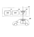
- FIG. 1 is a block diagram showing the configuration of the electric vehicle charging system according to the first embodiment.
- a charging system 100 a commercial power source 900, loads 910a and 910b, and electric vehicles 920a and 920b are connected by a power line. Electric power is supplied to 920a and 920b.
- a thick solid line indicates a power supply path
- a thin solid line indicates a signal path.
- the charging system 100 includes a measuring unit 110, a control device 120, and charging devices 130a and 130b. Each of these components may be provided in a separate device as a charging system or in the same device.
- the charging system 100 is installed in a consumer such as a convenience store or a shopping mall.
- the commercial power supply 900 supplies electric power such as alternating current (AC) 100V or 6600V to the loads 910a and 910b, the charging system 100, and the electric vehicles 920a and 920b.
- the loads 910a and 910b are loads on the consumer. For example, in the case of a convenience store, the loads are luminaires and refrigerators.
- the measurement unit 110 receives power from the commercial power source 900 and supplies current, voltage, frequency, harmonics such as harmonics of the voltage waveform to the charging devices 130a and 130b, ratios of harmonics to fundamental waves, power, The amount of electric power is measured, and these measured data are transmitted to the control device 120.
- the control device 120 is configured by a personal computer, a minicomputer, or a dedicated device, and controls charging of the charging devices 130a and 130b based on data from the measurement unit 110.
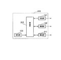
- FIG. 2 is a block diagram illustrating the configuration of the control device of the electric vehicle charging system according to the first embodiment.
- the control device 120 includes a receiving unit 121, a communication unit 122, an operation unit 123, and a control unit 124.
- the receiving unit 121 receives data from the measuring unit 110.
- the communication unit 122 transmits a command to each of the charging devices 130a and 130b.
- the operation unit 123 includes a switch and a liquid crystal panel, and as a value designated in advance, a current value that can be used for charging, that is, a current value or a voltage drop that is considered in relation to a contract current of a consumer is allowed. Electricity charges for each time zone, such as the lower voltage limit and the allowable harmonic magnitude, and the contract current of the customer are input.
- the control unit 124 controls each unit of the reception unit 121, the communication unit 122, and the operation unit 123.
- Charging devices 130a and 130b are provided corresponding to electric vehicles 920a and 920b, and charge storage battery unit 921 provided in electric vehicles 920a and 920b with electric power from a power line. This charging may be limited by the control device 120.
- the charging devices 130 a and 130 b include a communication unit 131, a control unit 132, and a current adjustment unit 133.
- the communication unit 131 receives a command transmitted from the communication unit 122 of the control device 120.
- the control unit 132 controls the current adjustment unit 133 so as to obtain an appropriate current in order to reduce the charging current in accordance with a command from the communication unit 131.
- the current adjustment unit 133 converts power supplied from the commercial power source 900 (alternating current or direct current, and in the case of alternating current, alternating current is converted into direct current) into a charging current, and the storage battery unit 921 of the electric vehicles 920a and 920b. To charge.
- the charging current is controlled by the control unit 132.
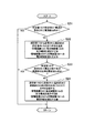
- FIG. FIG. 4 is a flowchart showing a charging process executed by the control unit 124 in the control device 120 of the electric vehicle charging system.
- the measurement unit 110 measures the current supplied from the commercial power supply 900, the voltage, the ratio of harmonics to the fundamental wave, and the like. It is checked whether or not the current measured by the measurement unit 110 is within a preset current value (step S11). If the measured current is not within the preset current value, a command to decrease the output current of the current adjustment unit 133 to the charging device 130 until the current value transmitted from the measurement unit 110 falls within the set value. Is transmitted (step S12).
- step S13 it is checked whether the voltage drop measured by the measurement unit 110 and the ratio of harmonics to the fundamental wave are within the set values. If the ratio of the voltage drop and the harmonic to the fundamental wave is not within the set value, the current to the charging device 130 until the ratio of the voltage value and the harmonic to the fundamental wave transmitted from the measurement unit 110 is within the set value. A command to decrease the output current of the adjustment unit 133 is transmitted (step S14).
- scheduling is performed so that a large current is generated in a time zone where the electricity rate is low and a low current is set in a time zone where the electricity rate is high, and the scheduling information is transmitted to the charging device 130 to charge the electric vehicles 920a and 920b. May be controlled.
- the measurement unit 110 measures at least one of the current, voltage, and harmonics of the commercial power supply 900, and the commercial power supply 900 measured by the measurement unit 110 is measured. Since the control unit 124 of the control device 120 transmits a command for controlling the charging of the storage battery unit 921 to the charging device 130 according to at least one information of current, voltage, and harmonics of the electric vehicle 920a, 920b It is possible to appropriately control the charging of the storage battery unit 921.
- FIG. 5 is a block diagram showing a configuration of an electric vehicle charging system according to the second embodiment.
- the electric vehicle charging system 200 of the second embodiment shown in FIG. 5 is further replaced with a power storage device 220 and a control device 120, compared to the electric vehicle charging system 100 of the first embodiment shown in FIG.
- charging devices 230a and 230b are provided.
- control device 210 has a communication unit 211 added to the configuration of the control device 120.
- Communication unit 211 transmits a command (command) instructing the amount of discharge to power storage device 220. That is, communication unit 211 transmits a command for supplying current from power storage device 220 to charging devices 230a and 230b.
- FIG. 7A is a block diagram showing a configuration of the power storage device 220 of the electric vehicle charging system according to the second embodiment
- FIG. 7B is a charging device of the electric vehicle charging system according to the second embodiment.
- the power storage device 220 is charged with the power supplied from the commercial power supply 900 by alternating current (AC) or direct current (DC) when the load 910a, 910b and the charging devices 230a, 230b use less power.
- the power storage device 220 supplies charging power to the charging devices 230a and 230b, and includes a communication unit 221, a control unit 222, a current / voltage variable unit 223, and a storage battery 224.
- the communication unit 221 receives a command indicating the discharge amount transmitted from the communication unit 211 of the control device 210.
- the control unit 222 controls the current value and voltage value of the current-voltage variable unit 223 in accordance with a command from the communication unit 221 that instructs the amount of discharge.
- the current voltage variable unit 223 varies the output current and output voltage of the storage battery 224 based on information from the control unit 222.
- the charging devices 230a and 230b are provided corresponding to the electric vehicles 920a and 920b, and include a communication unit 131, a control unit 132, a current adjustment unit 133, and a current conversion unit 231 as illustrated in FIG.
- the storage battery unit 921 provided in the electric vehicles 920a and 920b has a current obtained by adding the current supplied from the commercial power supply 900 via the current adjustment unit 133 and the current supplied from the power storage device 220 via the voltage conversion unit 231. Charged.
- the communication unit 131 receives a command transmitted from the communication unit 122 of the control device 210.
- the control unit 132 controls the current adjustment unit 133 so as to obtain an appropriate current in order to reduce the current supplied from the commercial power supply 900 in accordance with a command from the communication unit 131.
- the current adjustment unit 133 converts the power supplied from the commercial power supply 900 (AC or DC, and converts AC to DC in the case of AC) into a charging current and outputs the current.
- the output current is controlled by the control unit 132.
- Current conversion unit 231 converts the current supplied from power storage device 220 into a charging current for storage battery unit 921 of electric vehicle 920 and outputs the current. Note that when the power storage device 220 outputs alternating current, it is converted into direct current and output.
- FIG. 8 is a flowchart showing a charging process executed by the control unit in the control device of the electric vehicle charging system.
- the measurement unit 110 measures the current supplied from the commercial power supply 900, the voltage, the ratio of harmonics to the fundamental wave, and the like. It is checked whether or not the current measured by the measurement unit 110 is within a preset current value (step S21). If the measured current is not within the preset current value, a command to decrease the output current of the current adjustment unit 133 to the charging device 230 until the current value transmitted from the measurement unit 110 falls within the set value. Then, a command to increase current supply to charging device 230 is transmitted to power storage device 220 (step S22).
- step S23 it is checked whether the voltage drop and the ratio of harmonics to the fundamental wave measured by the measurement unit 110 are within the set values. If the ratio of the voltage drop and the harmonic to the fundamental wave is not within the set value, the current to the charging device 230 until the voltage value transmitted from the measurement unit 110 and the ratio of the harmonic to the fundamental wave are within the set value. A command to decrease the output current of adjustment unit 133 and a command to increase current supply to charging device 230 are transmitted to power storage device 220 (step S24).
- the charging of the electric vehicles 920a and 920b may be controlled using the current from the commercial power supply 900 during a time period when the electricity rate is low.
- the charging of the electric vehicles 920a and 920b is controlled by controlling at least one of the process of reducing the charging current and the process of using a large amount of current from the power storage device 220 during the time period when the electricity bill is expensive. May be.
- the current from the power storage device 220 can be supplied to the charging devices 230a and 230b, the voltage drop and the ratio of harmonics to the fundamental wave become smaller.
- FIG. 9 is a block diagram showing a configuration of an electric vehicle charging system according to the third embodiment.
- the electric vehicle charging system 300 according to the third embodiment illustrated in FIG. 9 further includes a communication unit 320 and data from the communication unit 320 with respect to the electric vehicle charging system 200 according to the second embodiment illustrated in FIG. And a control device 310 for receiving.
- the difference between the control device 310 and the control device 210 in the second embodiment is that it has an interface circuit with the communication unit 320 and only a program, and other configurations are the same. Accordingly, each part in the control device 310 is denoted by the same reference numeral as each part of the control device 210.
- the communication unit 320 is an interface unit with the Internet, a power line carrier communication device or a wireless communication device, information on the power usage status of the commercial power supply 900, for example, “electricity forecast” or “power reduction” individually transmitted to consumers.
- a message about a request (demand) ” is received, and the information is transmitted to the control device 310.
- FIG. 10 is a flowchart showing a charging process executed by the control unit in the control device of the electric vehicle charging system.
- step S31 it is checked whether information (demand) to reduce power or an electric forecast has been received via the communication unit 320 (step S31).
- a command to decrease the output current of the current adjusting unit 133 to the charging device 230, and a current supply to the charging device 230 to the power storage device 220 are increased.
- a command to transmit is transmitted (step S32).
- the control unit 212 of the control device 310 charges the storage battery unit 921 according to the information for reducing the power transmitted from the outside to the communication unit 320. Is transmitted to the charging device 130, and a command to increase the current supply from the power storage device 220 to the charging device 130 is transmitted to the power storage device 220. Therefore, charging of the storage battery unit 921 of the electric vehicles 920a and 920b is performed. Can be controlled appropriately.
- FIG. 11 is a block diagram illustrating a configuration of an electric vehicle charging system according to the fourth embodiment.
- the electric vehicle charging system 400 of the fourth embodiment shown in FIG. 11 differs from the electric vehicle charging system 300 of the third embodiment shown in FIG. 9 in the measurement unit 410, the power storage device 420, and the control device 430. .
- the difference between the control device 430 and the control device 210 in the second embodiment is that it has an interface circuit with the communication unit 320 and only a program, and other configurations are the same. Accordingly, each part in the control device 430 is denoted by the same reference numeral as each part of the control device 210.
- charging devices 130a and 130b are provided as in the first embodiment.
- the measurement unit 410 measures the power of the customer's loads 910a and 910b and the power to the charging devices 130a and 130b, and transmits the measured data to the control device 430.
- Power storage device 420 includes an inverter, converts direct current to alternating current, and supplies the output to charging devices 130a and 130b and loads 910a and 910b.
- FIG. FIG. 12 is a flowchart showing a charging process executed by the control unit in the control device 430 of the electric vehicle charging system.
- the measurement unit 410 measures the current supplied from the commercial power supply 900, the voltage, the ratio of harmonics to the fundamental wave, and the like. It is checked whether or not the current measured by the measurement unit 410 is within a preset current value (step S41). If the measured current is not within the preset current value, a command to increase the output current is transmitted to the power storage device 420 until the current value transmitted from the measurement unit 410 is equal to or less than the contract current. If the current is still not within the set current range, a command to decrease the output current of the current adjustment unit 133 is transmitted to the charging device 130 (step S42).
- step S43 it is checked whether the voltage drop and the ratio of the harmonics to the fundamental wave measured by the measurement unit 410 are within the set values.
- a command to increase the output voltage is transmitted to the power storage device 420. If it still does not fall within the set voltage value, a command to decrease the output current of the current adjusting unit 133 is transmitted to the charging device 130 (step S44).
- charging to the electric vehicles 920a and 920b may be controlled by controlling to increase the output current of the power storage device 420 in a time zone when the electricity charge of the commercial power supply 900 is expensive.
- the power is measured in consideration of the power of the customer's loads 910a and 910b, and the output of the power storage device 420 is determined according to the measured power. Can also be supplied to the charging devices 130a and 130b and the loads 910a and 910b.
- FIG. 13 is a block diagram illustrating a configuration of an electric vehicle charging system according to the fifth embodiment.
- the electric vehicle charging system 500 according to the fifth embodiment illustrated in FIG. 13 includes a solar power generation device 520 and a wind power generation device 530 as compared with the electric vehicle charging system 400 according to the fourth embodiment illustrated in FIG. 11. . Note that only one of the solar power generation device 520 and the wind power generation device 530 may be used.
- the solar power generation device 520 is also called a mega solar, and generates electric power by photoelectric conversion and outputs it to a power line.
- the wind power generator 530 generates electric power by converting wind power into electricity and outputs it to the power line.
- Control device 510 transmits a command to solar power generation device 520 and wind power generation device 530 so as to supply power to charging devices 310a and 310b.
- FIG. 14 is a flowchart illustrating a charging process executed by a control unit in the control device of the electric vehicle charging system.
- a power generation time zone schedule is created so that the power of the solar power generation device 520 and the wind power generation device 530 is used preferentially (step S51).
- the control device 510 controls the solar power generation device 520 and the wind power generation device 530 according to the power generation time zone schedule.
- step S52 it is checked whether or not the current from the commercial power source 900 measured by the measuring unit 410 exceeds the customer contract current (step S52).
- the output current of the power storage device 420 is increased, and when the current is still insufficient, the charging current of the charging device 130 is decreased. Control (step S53).
- the power of the solar power generation device 520 and the wind power generation device 530 can be preferentially used.
Landscapes
- Engineering & Computer Science (AREA)
- Power Engineering (AREA)
- Transportation (AREA)
- Mechanical Engineering (AREA)
- Manufacturing & Machinery (AREA)
- Chemical & Material Sciences (AREA)
- Chemical Kinetics & Catalysis (AREA)
- Electrochemistry (AREA)
- General Chemical & Material Sciences (AREA)
- Charge And Discharge Circuits For Batteries Or The Like (AREA)
- Electric Propulsion And Braking For Vehicles (AREA)
- Secondary Cells (AREA)
Abstract
商用電源の状況に応じて充電を制御することができる充電システム及び充電装置並びに充電方法。 本実施形態は、電力系統900と蓄電池部921とに接続された充電システムであって、蓄電池部921を充電する充電装置130と、電力系統900の電流、電圧及び高調波の少なくとも1つの情報を測定する測定部110と、測定部110で測定された少なくとも1つの情報に応じて、蓄電池部921への充電を制御するための命令を充電装置130に送信する制御装置120とを備える。
Description
本出願は、2011年8月29日に出願した先行する日本国特許出願第2011-186005号による優先権の利益に基礎をおき、かつ、その利益を求めており、その内容全体が引用によりここに包含される。
本実施形態は、例えば電気自動車等に搭載される蓄電池を充電する充電システム及び充電装置並びに充電方法に関する。
近年、電気自動車が普及しつつあり、この電気自動車には蓄電池が搭載されている。この蓄電池を充電する充電設備は、従来のガソリンスタンドのような充電スタンドの他に、コンビニエンスストアやショッピングモールにも配置される。
しかし、充電電流がかなり大きい場合には、電力会社と例えば120Aの電流契約をしていたコンビニエンスストアが契約電流を増加させて、例えば150Aで、契約しなければならない。このため、電気の基本料金が上昇することになる。従って、電気自動車の充電料金が上昇することになり、コンビニエンスストア等の経済も圧迫してしまう。
また、充電装置として、例えば、特許文献1に記載された技術が開示されている。この充電装置では、常時は交流電源から整流器と充電器とにより低電流の直流電力を得て、設備用蓄電池を充電しておく。電気自動車からの充電要求時には、蓄電池から充電器によって大電流の直流電力を得て、電気自動車等の蓄電池を急速充電する。このため、夜間等に蓄電池を充電できる。ここで、その技術に関して、下記文献を引用し、その内容全体を引用によりここに包含する。
しかしながら、特許文献1の充電装置では、商用電源(系統)の状況に応じて受電を制御することができなかった。例えば、電気自動車への充電電流が多大であり、需要家の契約電流を上回るような場合、需要家は電力会社との契約電流を上げなければならない。このため、電力料金の基本料金が上がり、電気自動車への充電費用が上がる。
また、特許文献1の充電装置では、商用系統の電力品質に応じて受電を制御することができなかった。
上述した状況に応じて、本実施形態では、電力系統と蓄電池部とに接続された充電システムであって、前記蓄電池部を充電する充電装置と、前記電力系統の電流、電圧及び高調波の少なくとも1つの情報を測定する測定部と、前記測定部で測定された少なくとも1つの情報に応じて、前記蓄電池部への充電を制御するための命令を前記充電装置に送信する制御装置とを備えた、充電システムを提供する。
実施形態の充電システム及び充電装置並びに充電方法によれば、商用系統の状況に応じて充電を制御することができる。
以下、図面を参照しながら、本実施形態の充電システム及び充電装置並びに充電方法を詳細に説明する。以下の実施形態では、充電システム及び充電装置並びに充電方法を例えば、電気自動車に適用した場合について説明する。なお、電気自動車に限らず、その蓄電池を搭載した他の負荷であっても良い。
(第1の実施形態)
図1は、第1の実施形態に係る電気自動車充電システムの構成を示すブロック図である。この電気自動車充電システムは、充電システム100、商用電源900、負荷910a,910b、電気自動車920a,920bが電力線で接続され、商用電源(商用系統)900から負荷910a,910b、充電システム100及び電気自動車920a,920bに電力が供給されるようになっている。図1において、太実線は電力供給の経路を示し、細実線は信号の経路を示している。
図1は、第1の実施形態に係る電気自動車充電システムの構成を示すブロック図である。この電気自動車充電システムは、充電システム100、商用電源900、負荷910a,910b、電気自動車920a,920bが電力線で接続され、商用電源(商用系統)900から負荷910a,910b、充電システム100及び電気自動車920a,920bに電力が供給されるようになっている。図1において、太実線は電力供給の経路を示し、細実線は信号の経路を示している。
充電システム100は、測定部110、制御装置120、充電装置130a,130bを備えている。これら各構成要件は、充電システムとして別装置に設けても良く、同一装置内に設けても良い。充電システム100は、コンビニエンスストアやショッピングモール等の需要家に設置されている。
商用電源900は、交流(AC)100Vや6600V等の電力を負荷910a,910b、充電システム100、及び電気自動車920a,920bに供給する。負荷910a,910bは、需要家の負荷であり、例えば、コンビニエンスストアの場合には照明器具や冷蔵庫等である。
測定部110は、商用電源900からの電力を受けて、充電装置130a,130bに供給される電流、電圧、周波数、電圧波形の高調波等の異常波形及び高調波の基本波に対する比率、電力、電力量を測定して、これらの測定されたデータを制御装置120に送信する。
制御装置120は、パーソナルコンピュータやミニコンピュータ、専用機器により構成され、測定部110からのデータに基づき充電装置130a,130bの充電を制御する。図2は、第1の実施形態に係る電気自動車充電システムの制御装置の構成を示すブロック図である。制御装置120は、受信部121、通信部122、操作部123、制御部124を備えている。
受信部121は、測定部110からのデータを受信する。通信部122は、各充電装置130a,130bに命令を送信する。操作部123は、スイッチや液晶パネルで構成され、予め指定される値として、充電に使用可能な電流値、即ち需要家の契約電流との関係で考えられた電流値、電圧降下が許容される電圧下限値、許容可能な高調波の大きさ等、時間帯毎の電気料金、需要家の契約電流が入力される。制御部124は、受信部121、通信部122、操作部123の各部を制御する。
充電装置130a,130bは、電気自動車920a,920bに対応して設けられ、電力線からの電力により電気自動車920a,920bに設けられた蓄電池部921を充電する。この充電は制御装置120により制限されることもある。充電装置130a,130bは、通信部131、制御部132、電流調整部133を備えている。
通信部131は、制御装置120の通信部122から送信されてくる命令を受信する。制御部132は、通信部131からの命令に従って、充電電流を減少させるために、適切な電流にするよう電流調整部133を制御する。電流調整部133は、商用電源900から供給された電力(交流又は直流、交流の場合には交流を直流に変換する。)を充電用の電流に変換し、電気自動車920a,920bの蓄電池部921を充電する。充電電流は制御部132により制御される。
次に、上記のように構成される電気自動車充電システムの動作を説明する。以下では、制御装置120内の制御部124の動作を中心に説明する。図4は、電気自動車充電システムの制御装置120内の制御部124で実行される充電処理を示すフローチャートである。
次に、上記のように構成される電気自動車充電システムの動作を説明する。以下では、制御装置120内の制御部124の動作を中心に説明する。図4は、電気自動車充電システムの制御装置120内の制御部124で実行される充電処理を示すフローチャートである。
まず、測定部110で商用電源900から供給される電流、電圧、高調波の基本波に対する比率等が測定される。測定部110で測定された電流が予め設定された電流値内かどうかが調べられる(ステップS11)。測定された電流が予め設定された電流値内でない場合には、測定部110から送信される電流値が設定値内になるまで、充電装置130に対し電流調整部133の出力電流を減少させる命令を送信する(ステップS12)。
次に、測定部110で測定された電圧の降下及び高調波の基本波に対する比率が設定値内かどうかが調べられる(ステップS13)。電圧の降下及び高調波の基本波に対する比率が設定値内でない場合には、測定部110から送信される電圧値及び高調波の基本波に対する比率が設定値内になるまで充電装置130に対し電流調整部133の出力電流を減少させる命令を送信する(ステップS14)。
なお、電気料金が安価な時間帯に大電流とし、電気料金が高価な時間帯が小電流となるようにスケジューリングしてそのスケジューリング情報を充電装置130に送信し、電気自動車920a,920bへの充電を制御しても良い。
このように、第1の実施形態の電気自動車充電システムによれば、測定部110で商用電源900の電流、電圧及び高調波の少なくとも1つを測定し、測定部110で測定された商用電源900の電流、電圧、高調波の少なくとも1つの情報に応じて、制御装置120の制御部124が蓄電池部921への充電を制御するための命令を充電装置130に送信するので、電気自動車920a,920bの蓄電池部921への充電を適正に制御することができる。
(第2の実施形態)
図5は、第2の実施形態に係る電気自動車充電システムの構成を示すブロック図である。図5に示す第2の実施形態の電気自動車充電システム200は、図1に示す第1の実施形態の電気自動車充電システム100に対して、さらに、蓄電装置220と、制御装置120に代えて、制御装置210、充電装置130a、130bに代えて充電装置230a、230bとを備えている。
図5は、第2の実施形態に係る電気自動車充電システムの構成を示すブロック図である。図5に示す第2の実施形態の電気自動車充電システム200は、図1に示す第1の実施形態の電気自動車充電システム100に対して、さらに、蓄電装置220と、制御装置120に代えて、制御装置210、充電装置130a、130bに代えて充電装置230a、230bとを備えている。
制御装置210は、制御装置120の構成に、図6に示すように、通信部211が追加されている。通信部211は、蓄電装置220に対して放電量を指示する命令(コマンド)を送信する。即ち、通信部211は、蓄電装置220から充電装置230a,230bへ電流を供給する命令を送信する。
図7(a)は、第2の実施形態に係る電気自動車充電システムの蓄電装置220の構成を示すブロック図、図7(b)は、第2の実施形態に係る電気自動車充電システムの充電装置230の構成を示すブロック図である。蓄電装置220は、負荷910a、910b、充電装置230a、230bでの電力使用が少ないときに、交流(AC)または直流(DC)にて、商用電源900から供給される電力にて充電される。蓄電装置220は、充電装置230a,230bに対して、充電電力を供給するもので、通信部221、制御部222、電流電圧可変部223、蓄電池224を備えている。
通信部221は、制御装置210の通信部211から送信される放電量を指示する命令を受信する。制御部222は、通信部221からの放電量を指示する命令に応じて、電流電圧可変部223の電流値、電圧値を制御する。電流電圧可変部223は、制御部222からの情報に基づき、蓄電池224の出力電流、出力電圧を可変する。
充電装置230a、230bは電気自動車920a、920bに対応して設けられ、図7(b)に示すとおり通信部131、制御部132、電流調整部133、電流変換部231を備えている。
電気自動車920a、920bに設けられた蓄電池部921は電流調整部133を介し商用電源900から供給される電流と、電圧変換部231を介し蓄電装置220から供給される電流とが加算された電流により充電される。
通信部131は、制御装置210の通信部122から送信される命令を受信する。制御部132は、通信部131からの命令に従って、商用電源900から供給される電流を減少させるために、適切な電流にするよう電流調整部133を制御する。電流調整部133は、商用電源900から供給された電力(交流又は直流、交流の場合には交流を直流に変換する。)を充電用の電流に変換し出力する。その出力電流は制御部132により制御される。
電流変換部231は、蓄電装置220から供給される電流を、電気自動車920の蓄電池部921の充電用の電流に変換して出力する。なお、蓄電装置220が交流を出力するものである場合は直流に変換して出力する。
電流変換部231は、蓄電装置220から供給される電流を、電気自動車920の蓄電池部921の充電用の電流に変換して出力する。なお、蓄電装置220が交流を出力するものである場合は直流に変換して出力する。
次に、上記のように構成される電気自動車充電システムの動作を説明する。以下では、制御装置210内の制御部212の動作を中心に説明する。図8は、電気自動車充電システムの制御装置内の制御部で実行される充電処理を示すフローチャートである。
まず、測定部110で商用電源900から供給される電流、電圧、高調波の基本波に対する比率等が測定される。測定部110で測定された電流が予め設定された電流値内かどうかが調べられる(ステップS21)。測定された電流が予め設定された電流値内でない場合には、測定部110から送信される電流値が設定値内になるまで、充電装置230に対し電流調整部133の出力電流を減少させる命令、蓄電装置220に対し充電装置230への電流供給を増加する命令を送信する(ステップS22)。
次に、測定部110で測定された電圧の降下及び高調波の基本波に対する比率が設定値内かどうかが調べられる(ステップS23)。電圧の降下及び高調波の基本波に対する比率が設定値内でない場合には、測定部110から送信される電圧値及び高調波の基本波に対する比率が設定値内になるまで充電装置230に対し電流調整部133の出力電流を減少させる命令、蓄電装置220に対し充電装置230への電流供給を増加する命令を送信する(ステップS24)。
なお、電気料金が安価な時間帯には商用電源900からの電流を利用して電気自動車920a,920bへの充電を制御しても良い。また、電気料金が高価な時間帯には充電電流を減少させる処理と蓄電装置220からの電流を多く利用する処理との少なくとも一方を制御することにより、電気自動車920a,920bへの充電を制御しても良い。
このように、第2の実施形態の充電システムによれば、蓄電装置220からの電流を充電装置230a,230bに供給できるので、電圧の降下及び高調波の基本波に対する比率がより小さくなる。
(第3の実施形態)
図9は、第3の実施形態に係る電気自動車充電システムの構成を示すブロック図である。図9に示す第3の実施形態の電気自動車充電システム300は、図5に示す第2の実施形態の電気自動車充電システム200に対して、さらに、通信部320と、通信部320からのデータを受信する制御装置310とを備えている。なお、制御装置310と実施例2における制御装置210の相違点は、通信部320とのインターフェース回路を有することと、プログラムのみであり、その他の構成は同様である。従って、制御装置310内の各部は制御装置210の各部と同符号にて表記するものとする。
図9は、第3の実施形態に係る電気自動車充電システムの構成を示すブロック図である。図9に示す第3の実施形態の電気自動車充電システム300は、図5に示す第2の実施形態の電気自動車充電システム200に対して、さらに、通信部320と、通信部320からのデータを受信する制御装置310とを備えている。なお、制御装置310と実施例2における制御装置210の相違点は、通信部320とのインターフェース回路を有することと、プログラムのみであり、その他の構成は同様である。従って、制御装置310内の各部は制御装置210の各部と同符号にて表記するものとする。
通信部320は、インターネットとのインタフェースユニットや電力線搬送通信装置又は無線通信装置、商用電源900の電力使用状況に関する情報、例えば、「電気予報」や個別に需要家に対して送信される「電力削減要求(デマンド)に関する電文」を受信し、これらの情報を制御装置310に送信する。
次に、上記のように構成される電気自動車充電システムの動作を説明する。以下では、制御装置310内の制御部212の動作を中心に説明する。図10は、電気自動車充電システムの制御装置内の制御部で実行される充電処理を示すフローチャートである。
まず、通信部320を介して電力を削減すべき情報(デマンド)、電気予報を受信したかどうかが調べられる(ステップS31)。電力を削減すべき情報(デマンド)、電気予報を受信した場合には、充電装置230に対し電流調整部133の出力電流を減少させる命令、蓄電装置220に対し充電装置230への電流供給を増加する命令を送信する(ステップS32)。
このように、第3の実施形態の充電システムによれば、外部から通信部320を送られてきた電力を削減すべき情報に応じて、制御装置310の制御部212が蓄電池部921への充電を制御するための命令を充電装置130に送信、及び蓄電装置220から充電装置130への電流供給を増加する命令を蓄電装置220に送信するので、電気自動車920a,920bの蓄電池部921への充電を適正に制御することができる。
(第4の実施形態)
図11は、第4の実施形態に係る電気自動車充電システムの構成を示すブロック図である。図11に示す第4の実施形態の電気自動車充電システム400は、図9に示す第3の実施形態の電気自動車充電システム300に対して、測定部410と、蓄電装置420、制御装置430が異なる。なお、制御装置430と実施例2における制御装置210の相違点は、通信部320とのインターフェース回路を有することと、プログラムのみであり、その他の構成は同様である。従って、制御装置430内の各部は制御装置210の各部と同符号にて表記するものとする。また、充電装置230a、230bに代えて、実施例1と同様、充電装置130a、130bが設けられている。
図11は、第4の実施形態に係る電気自動車充電システムの構成を示すブロック図である。図11に示す第4の実施形態の電気自動車充電システム400は、図9に示す第3の実施形態の電気自動車充電システム300に対して、測定部410と、蓄電装置420、制御装置430が異なる。なお、制御装置430と実施例2における制御装置210の相違点は、通信部320とのインターフェース回路を有することと、プログラムのみであり、その他の構成は同様である。従って、制御装置430内の各部は制御装置210の各部と同符号にて表記するものとする。また、充電装置230a、230bに代えて、実施例1と同様、充電装置130a、130bが設けられている。
測定部410は、需要家の負荷910a,910bの電力、及び充電装置130a,130bへの電力を測定して、測定されたデータを制御装置430に送信する。蓄電装置420は、インバータを搭載し、直流を交流に変換してその出力を充電装置130a,130b及び負荷910a,910bに供給する。
次に、上記のように構成される電気自動車充電システムの動作を説明する。以下では、制御装置430内の制御部の動作を中心に説明する。図12は、電気自動車充電システムの制御装置430内の制御部で実行される充電処理を示すフローチャートである。
まず、測定部410で商用電源900から供給される電流、電圧、高調波の基本波に対する比率等が測定される。測定部410で測定された電流が予め設定された電流値内かどうかが調べられる(ステップS41)。測定された電流が予め設定された電流値内でない場合には、測定部410から送信される電流値が契約電流以下になるまで、蓄電装置420に対し出力電流を増加させる命令を送信する。それでもなお、設定された電流地以内にならない場合は、充電装置130に対し電流調整部133の出力電流を減少させる命令を送信する(ステップS42)。
次に、測定部410で測定された電圧の降下及び高調波の基本波に対する比率が設定値内かどうかが調べられる(ステップS43)。電圧の降下及び高調波の基本波に対する比率が設定値内でない場合には、蓄電装置420に対し出力電圧を増加させる命令を送信する。それでもなお、設定された電圧値以内にならない場合は、充電装置130に対し電流調整部133の出力電流を減少させる命令を送信する(ステップS44)。
なお、商用電源900の電気料金が高価な時間帯では、蓄電装置420の出力電流を増加させるように制御することにより、電気自動車920a,920bへの充電を制御しても良い。
このように、第4の実施形態の電気自動車充電システムによれば、需要家の負荷910a,910bの電力をも考慮して電力を測定し、測定された電力に応じて、蓄電装置420の出力を充電装置130a,130b及び負荷910a,910bにも供給することができる。
(第5の実施形態)
図13は、第5の実施形態に係る電気自動車充電システムの構成を示すブロック図である。図13に示す第5の実施形態の電気自動車充電システム500は、図11に示す第4の実施形態の電気自動車充電システム400に対して、太陽光発電装置520、風力発電装置530を備えている。なお、太陽光発電装置520と風力発電装置530との一方のみを用いても良い。
図13は、第5の実施形態に係る電気自動車充電システムの構成を示すブロック図である。図13に示す第5の実施形態の電気自動車充電システム500は、図11に示す第4の実施形態の電気自動車充電システム400に対して、太陽光発電装置520、風力発電装置530を備えている。なお、太陽光発電装置520と風力発電装置530との一方のみを用いても良い。
太陽光発電装置520は、メガソーラーとも呼ばれ、光電変換により電力を発生して電力線に出力する。風力発電装置530は、風力を電気に変換することにより電力を発生して電力線に出力する。制御装置510は、充電装置310a,310bに電力を供給するように太陽光発電装置520と風力発電装置530とに対して命令を送信する。
次に、上記のように構成される電気自動車充電システムの動作を説明する。以下では、制御装置510内の制御部の動作を中心に説明する。図14は、電気自動車充電システムの制御装置内の制御部で実行される充電処理を示すフローチャートである。
まず、太陽光発電装置520、風力発電装置530の電力を優先して使用するように、電力発電時間帯スケジュールを作成する(ステップS51)。この場合には、制御装置510は、太陽光発電装置520、風力発電装置530を電力発電時間帯スケジュールに従って制御する。
次に、測定部410で測定された商用電源900からの電流が需要家の契約電流を超えたかどうかが調べられる(ステップS52)。商用電源900からの電流が需要家の契約電流を超えた場合には、蓄電装置420の出力電流を増加し、それでも電流が不足である場合には、充電装置130の充電電流を減少させるように制御する(ステップS53)。
このように、第5の実施形態の電気自動車充電システムによれば、太陽光発電装置520、風力発電装置530の電力を優先して使用できる。
以上のように、本発明のいくつかの実施形態を説明したが、これらの実施形態は、例として提示したものであり、発明の範囲を限定することは意図していない。これら新規な実施形態は、その他の様々な形態で実施されることが可能であり、発明の要旨を逸脱しない範囲で、種々の省略、置き換え、変更を行うことができる。これら実施形態やその変形は、発明の範囲や要旨に含まれるとともに、特許請求の範囲に記載された発明とその均等の範囲に含まれる。
100,200,300,400,500 充電システム
110,410 測定部
120,210,310,510 制御装置
121 受信部
122,131,211,221,320 通信部
123 操作部
124,132,222 制御部
130a,130b 充電装置
133 電流調整部
220,420 蓄電装置
223 電流電圧可変部
224 蓄電池
520 太陽光発電装置
530 風力発電装置
900 商用電源
910a,910b 負荷
920a,920b 電気自動車
921 蓄電池部
110,410 測定部
120,210,310,510 制御装置
121 受信部
122,131,211,221,320 通信部
123 操作部
124,132,222 制御部
130a,130b 充電装置
133 電流調整部
220,420 蓄電装置
223 電流電圧可変部
224 蓄電池
520 太陽光発電装置
530 風力発電装置
900 商用電源
910a,910b 負荷
920a,920b 電気自動車
921 蓄電池部
Claims (15)
- 電力系統と蓄電池部とに接続された充電システムであって、
前記蓄電池部を充電する充電装置と、
前記電力系統の電流、電圧及び高調波の少なくとも1つの情報を測定する測定部と、
前記測定部で測定された少なくとも1つの情報に応じて、前記蓄電池部への充電を制御するための命令を前記充電装置に送信する制御装置と、
を備えることを特徴とする充電システム。
- 前記制御装置は、前記電流が設定値を超えるとき、前記充電装置への電流を前記設定値になるまで減少させるための命令を前記充電装置に送信することを特徴とする請求項1記載の充電システム。
- 前記充電装置に対して電力を供給する蓄電装置を備え、
前記充電装置は、前記電力系統から供給された電流と、前記蓄電装置から供給された電流とを加算した電流を、前記蓄電池部に対し供給することを特徴とする請求項1記載の充電システム。
- 前記制御装置は、前記電力系統からの電流を予め設定された電流値以下に制御することを特徴とする請求項1記載の充電システム。
- 前記制御装置は、時間帯毎の電気料金の価格に基づき、前記充電装置への電流を減少させるための命令を前記充電装置に送信する処理と前記蓄電装置から前記充電装置への電流供給を増加するための命令を前記蓄電装置に送信する処理との少なくとも1つを実行することを特徴とする請求項3記載の充電システム。
- 外部からの電力削減指示を受信する通信部と、
前期制御装置は、前記通信部で受信した電力削減指示に応じて、前記充電装置への電流を減少させるための命令を前記充電装置に送信する処理と前記蓄電装置から前記充電装置への電流供給を増加するための命令を前記蓄電装置に送信する処理との少なくとも1つを実行することを特徴とする請求項3記載の充電システム。
- 太陽光発電装置と風力発電装置との少なくとも一方を備え、
前記制御装置は、前記太陽光発電装置と前記風力発電装置との少なくとも一方に対して前記充電装置へ電力を優先して供給するように命令を送信することを特徴とする請求項5記載の充電システム。
- 充電装置により蓄電池部を充電する充電ステップと、
電力系統の電流、電圧及び高調波の少なくとも1つの情報を測定する測定ステップと、
前記測定ステップで測定された少なくとも1つの情報に応じて、前記蓄電池部への充電を制御するための命令を前記充電装置に送信する制御ステップと、
を備えることを特徴とする充電方法。
- 前記制御ステップは、前記電流が設定値を超えるとき、前記充電装置への電流を前記設定値になるまで減少させるための命令を前記充電装置に送信することを特徴とする請求項8記載の充電方法。
- 前記電力系統から供給された電流と、前記充電装置に対して電力を供給する蓄電装置から供給された電流とを加算した電流を、前記蓄電池部に対し供給することを特徴とする請求項8記載の充電方法。
- 前記制御ステップは、前記電力系統からの電流を予め設定された電流値以下に制御することを特徴とする請求項8記載の充電方法。
- 前記制御ステップは、時間帯毎の電気料金の価格に基づき、前記充電装置への電流を減少させるための命令を前記充電装置に送信する処理と前記蓄電装置から前記充電装置への電流供給を増加するための命令を前記蓄電装置に送信する処理との少なくとも1つを実行することを特徴とする請求項10記載の充電方法。
- 外部からの電力削減指示を受信する通信ステップと、をさらに備え、
前期制御ステップは、前記通信ステップで受信した電力削減指示に応じて、前記充電装置への電流を減少させるための命令を前記充電装置に送信する処理と前記蓄電装置から前記充電装置への電流供給を増加するための命令を前記蓄電装置に送信する処理との少なくとも1つを実行することを特徴とする請求項10記載の充電方法。
- 前記制御ステップは、太陽光発電装置と風力発電装置との少なくとも一方に対して前記充電装置へ電力を優先して供給するように命令を送信することを特徴とする請求項12記載の充電方法。
- 蓄電池部を充電する充電装置であって、
電力系統の電流、電圧及び高調波の少なくとも1つの情報に応じて、前記蓄電池部への充電を制御するための命令を受信する通信部と、
前記通信部で受信された前記命令に従って前記蓄電池部への電流を減少させることにより適正値に制御する制御部と、
を備えることを特徴とする充電装置。
Priority Applications (3)
| Application Number | Priority Date | Filing Date | Title |
|---|---|---|---|
| CN201280030751.7A CN103636099A (zh) | 2011-08-29 | 2012-06-29 | 充电系统、充电装置以及充电方法 |
| EP12828100.3A EP2752967A4 (en) | 2011-08-29 | 2012-06-29 | CHARGING SYSTEM, LOADING DEVICE AND LOADING PROCEDURE |
| US14/154,926 US20140176051A1 (en) | 2011-08-29 | 2014-01-14 | Charging system, charging apparatus, and charging method |
Applications Claiming Priority (2)
| Application Number | Priority Date | Filing Date | Title |
|---|---|---|---|
| JP2011186005A JP2013048519A (ja) | 2011-08-29 | 2011-08-29 | 充電システム及び充電装置並びに充電方法 |
| JP2011-186005 | 2011-08-29 |
Related Child Applications (1)
| Application Number | Title | Priority Date | Filing Date |
|---|---|---|---|
| US14/154,926 Continuation US20140176051A1 (en) | 2011-08-29 | 2014-01-14 | Charging system, charging apparatus, and charging method |
Publications (1)
| Publication Number | Publication Date |
|---|---|
| WO2013031073A1 true WO2013031073A1 (ja) | 2013-03-07 |
Family
ID=47755607
Family Applications (1)
| Application Number | Title | Priority Date | Filing Date |
|---|---|---|---|
| PCT/JP2012/004238 Ceased WO2013031073A1 (ja) | 2011-08-29 | 2012-06-29 | 充電システム及び充電装置並びに充電方法 |
Country Status (5)
| Country | Link |
|---|---|
| US (1) | US20140176051A1 (ja) |
| EP (1) | EP2752967A4 (ja) |
| JP (1) | JP2013048519A (ja) |
| CN (1) | CN103636099A (ja) |
| WO (1) | WO2013031073A1 (ja) |
Cited By (2)
| Publication number | Priority date | Publication date | Assignee | Title |
|---|---|---|---|---|
| JP2018523959A (ja) * | 2015-08-04 | 2018-08-23 | ヴォッベン プロパティーズ ゲーエムベーハーWobben Properties Gmbh | 電気車両充電ステーションおよび電気車両充電ステーションを制御するための方法 |
| US11427103B2 (en) | 2017-04-21 | 2022-08-30 | Wobben Properties Gmbh | Method for operating a charging station |
Families Citing this family (8)
| Publication number | Priority date | Publication date | Assignee | Title |
|---|---|---|---|---|
| CN104518536B (zh) * | 2013-09-29 | 2017-03-01 | 国际商业机器公司 | 充电系统、充电控制装置和充电方法 |
| TWI559648B (zh) * | 2014-01-21 | 2016-11-21 | 台達電子工業股份有限公司 | 動態充電之充電裝置及其操作方法 |
| CN105244931B (zh) * | 2014-09-30 | 2019-03-19 | 珠海泰坦科技股份有限公司 | 基于城市基础设施的电动车辆充电管理方法及系统 |
| US10288659B2 (en) | 2015-03-20 | 2019-05-14 | General Electric Company | System and method for determining identity information of an electrically operable machine |
| DE102016214518A1 (de) * | 2016-08-05 | 2018-02-08 | Robert Bosch Gmbh | Verfahren zum Betrieb eines netzbetriebenen Ladegeräts an einer nichtsinusförmigen Netzspannung |
| KR102271474B1 (ko) * | 2019-10-24 | 2021-07-01 | (주)제주전기자동차서비스 | 전기자동차 충전기 검사장치 |
| JP7554989B2 (ja) * | 2019-11-08 | 2024-09-24 | パナソニックIpマネジメント株式会社 | 充電システム、充電方法、及びプログラム |
| WO2022169812A1 (en) * | 2021-02-02 | 2022-08-11 | Iotecha Corp. | Methods, devices, and systems utilizing electric vehicle charging responsive to identified power signatures in an aggregate power waveform |
Citations (4)
| Publication number | Priority date | Publication date | Assignee | Title |
|---|---|---|---|---|
| JPH05207668A (ja) | 1992-01-24 | 1993-08-13 | Nissan Motor Co Ltd | 充電装置 |
| JPH06178461A (ja) * | 1992-12-09 | 1994-06-24 | Japan Storage Battery Co Ltd | 系統連系電源システム |
| JP2007535282A (ja) * | 2003-07-10 | 2007-11-29 | エアロヴァイロンメント インコーポレイテッド | バッテリー充電システム及び方法 |
| JP2011151896A (ja) * | 2010-01-19 | 2011-08-04 | Toshiba Corp | 充放電制御装置 |
Family Cites Families (6)
| Publication number | Priority date | Publication date | Assignee | Title |
|---|---|---|---|---|
| JP3923765B2 (ja) * | 2001-09-18 | 2007-06-06 | 株式会社日立製作所 | 電気機器システム |
| JP2003339118A (ja) * | 2002-05-22 | 2003-11-28 | My Way Giken Kk | 分散電源システム |
| KR100486548B1 (ko) * | 2002-12-21 | 2005-05-03 | 엘지전자 주식회사 | 이동 통신 단말기의 충전 시스템 및 그 방법 |
| US20100017045A1 (en) * | 2007-11-30 | 2010-01-21 | Johnson Controls Technology Company | Electrical demand response using energy storage in vehicles and buildings |
| US8384358B2 (en) * | 2009-05-28 | 2013-02-26 | GM Global Technology Operations LLC | Systems and methods for electric vehicle charging and for providing notification of variations from charging expectations |
| ES2350225B1 (es) * | 2009-06-16 | 2011-11-08 | Nucleo De Comunicaciones Y Control, S.L. | Sistema y metodo de control de recarga para vehiculos electricos pararedes de energia inteligentes. |
-
2011
- 2011-08-29 JP JP2011186005A patent/JP2013048519A/ja active Pending
-
2012
- 2012-06-29 EP EP12828100.3A patent/EP2752967A4/en not_active Withdrawn
- 2012-06-29 WO PCT/JP2012/004238 patent/WO2013031073A1/ja not_active Ceased
- 2012-06-29 CN CN201280030751.7A patent/CN103636099A/zh active Pending
-
2014
- 2014-01-14 US US14/154,926 patent/US20140176051A1/en not_active Abandoned
Patent Citations (4)
| Publication number | Priority date | Publication date | Assignee | Title |
|---|---|---|---|---|
| JPH05207668A (ja) | 1992-01-24 | 1993-08-13 | Nissan Motor Co Ltd | 充電装置 |
| JPH06178461A (ja) * | 1992-12-09 | 1994-06-24 | Japan Storage Battery Co Ltd | 系統連系電源システム |
| JP2007535282A (ja) * | 2003-07-10 | 2007-11-29 | エアロヴァイロンメント インコーポレイテッド | バッテリー充電システム及び方法 |
| JP2011151896A (ja) * | 2010-01-19 | 2011-08-04 | Toshiba Corp | 充放電制御装置 |
Non-Patent Citations (1)
| Title |
|---|
| See also references of EP2752967A4 |
Cited By (3)
| Publication number | Priority date | Publication date | Assignee | Title |
|---|---|---|---|---|
| JP2018523959A (ja) * | 2015-08-04 | 2018-08-23 | ヴォッベン プロパティーズ ゲーエムベーハーWobben Properties Gmbh | 電気車両充電ステーションおよび電気車両充電ステーションを制御するための方法 |
| US10479210B2 (en) | 2015-08-04 | 2019-11-19 | Wobben Properties Gmbh | Electric vehicle charging station and method for controlling an electric vehicle charging station |
| US11427103B2 (en) | 2017-04-21 | 2022-08-30 | Wobben Properties Gmbh | Method for operating a charging station |
Also Published As
| Publication number | Publication date |
|---|---|
| EP2752967A1 (en) | 2014-07-09 |
| CN103636099A (zh) | 2014-03-12 |
| US20140176051A1 (en) | 2014-06-26 |
| EP2752967A4 (en) | 2015-04-01 |
| JP2013048519A (ja) | 2013-03-07 |
Similar Documents
| Publication | Publication Date | Title |
|---|---|---|
| WO2013031073A1 (ja) | 充電システム及び充電装置並びに充電方法 | |
| US9457672B2 (en) | Charging apparatus with dynamical charging power and method of operating the same | |
| US9379549B2 (en) | Electric power control system and method | |
| FR2943188B1 (fr) | Dispositif de charge rapide pour un vehicule electrique. | |
| JP6082886B2 (ja) | 電力調整装置及び電力調整方法 | |
| WO2015041253A1 (ja) | 充電設備および充電設備のエネルギーマネジメント方法 | |
| TWI501504B (zh) | 行動載具之充電裝置 | |
| JP2013258845A (ja) | 電力供給システム | |
| JP2013031243A (ja) | 充電用の電力管理システムおよびその電力管理装置 | |
| US11277008B2 (en) | Energy storage system | |
| JP2014230455A (ja) | 発電装置 | |
| US20200274363A1 (en) | Storage-batteries supervisory control system, charge/discharge control system, control device, and terminal device | |
| US9804212B2 (en) | Energy management system | |
| US8436574B2 (en) | Solar power supply system and driving method of same | |
| JP7242238B2 (ja) | 電力変換装置及び分散型電源システム | |
| JP2015192549A (ja) | 電力変換装置及び電力変換方法 | |
| WO2013151133A1 (ja) | 配電装置および電力供給システム | |
| KR101409272B1 (ko) | 신재생 에너지 연계 전력 시스템 | |
| WO2018070037A1 (ja) | 電力変換システム、電力供給システムおよび電力変換装置 | |
| US12316127B2 (en) | Power conversion device | |
| KR20200086835A (ko) | Ups를 이용한 수용가 부하 관리 시스템 | |
| JP2016195513A (ja) | 交流電源装置の出力電力制御方法及び交流電源装置 | |
| JP6478032B2 (ja) | 制御装置およびそれを利用した配電システム | |
| JP6207917B2 (ja) | 制御装置 | |
| US10418821B2 (en) | Power converting apparatus and power converting method |
Legal Events
| Date | Code | Title | Description |
|---|---|---|---|
| 121 | Ep: the epo has been informed by wipo that ep was designated in this application |
Ref document number: 12828100 Country of ref document: EP Kind code of ref document: A1 |
|
| WWE | Wipo information: entry into national phase |
Ref document number: 2012828100 Country of ref document: EP |
|
| NENP | Non-entry into the national phase |
Ref country code: DE |