WO2013035778A1 - 電熱線入り合せガラス - Google Patents
電熱線入り合せガラス Download PDFInfo
- Publication number
- WO2013035778A1 WO2013035778A1 PCT/JP2012/072717 JP2012072717W WO2013035778A1 WO 2013035778 A1 WO2013035778 A1 WO 2013035778A1 JP 2012072717 W JP2012072717 W JP 2012072717W WO 2013035778 A1 WO2013035778 A1 WO 2013035778A1
- Authority
- WO
- WIPO (PCT)
- Prior art keywords
- heating wire
- adhesive layer
- thickness
- laminated glass
- lower adhesive
- Prior art date
- Legal status (The legal status is an assumption and is not a legal conclusion. Google has not performed a legal analysis and makes no representation as to the accuracy of the status listed.)
- Ceased
Links
Images






Classifications
-
- B—PERFORMING OPERATIONS; TRANSPORTING
- B32—LAYERED PRODUCTS
- B32B—LAYERED PRODUCTS, i.e. PRODUCTS BUILT-UP OF STRATA OF FLAT OR NON-FLAT, e.g. CELLULAR OR HONEYCOMB, FORM
- B32B17/00—Layered products essentially comprising sheet glass, or glass, slag, or like fibres
- B32B17/06—Layered products essentially comprising sheet glass, or glass, slag, or like fibres comprising glass as the main or only constituent of a layer, next to another layer of a specific material
- B32B17/10—Layered products essentially comprising sheet glass, or glass, slag, or like fibres comprising glass as the main or only constituent of a layer, next to another layer of a specific material of synthetic resin
- B32B17/10005—Layered products essentially comprising sheet glass, or glass, slag, or like fibres comprising glass as the main or only constituent of a layer, next to another layer of a specific material of synthetic resin laminated safety glass or glazing
- B32B17/10009—Layered products essentially comprising sheet glass, or glass, slag, or like fibres comprising glass as the main or only constituent of a layer, next to another layer of a specific material of synthetic resin laminated safety glass or glazing characterized by the number, the constitution or treatment of glass sheets
- B32B17/10036—Layered products essentially comprising sheet glass, or glass, slag, or like fibres comprising glass as the main or only constituent of a layer, next to another layer of a specific material of synthetic resin laminated safety glass or glazing characterized by the number, the constitution or treatment of glass sheets comprising two outer glass sheets
-
- B—PERFORMING OPERATIONS; TRANSPORTING
- B32—LAYERED PRODUCTS
- B32B—LAYERED PRODUCTS, i.e. PRODUCTS BUILT-UP OF STRATA OF FLAT OR NON-FLAT, e.g. CELLULAR OR HONEYCOMB, FORM
- B32B17/00—Layered products essentially comprising sheet glass, or glass, slag, or like fibres
- B32B17/06—Layered products essentially comprising sheet glass, or glass, slag, or like fibres comprising glass as the main or only constituent of a layer, next to another layer of a specific material
- B32B17/10—Layered products essentially comprising sheet glass, or glass, slag, or like fibres comprising glass as the main or only constituent of a layer, next to another layer of a specific material of synthetic resin
- B32B17/10005—Layered products essentially comprising sheet glass, or glass, slag, or like fibres comprising glass as the main or only constituent of a layer, next to another layer of a specific material of synthetic resin laminated safety glass or glazing
- B32B17/10165—Functional features of the laminated safety glass or glazing
- B32B17/10339—Specific parts of the laminated safety glass or glazing being colored or tinted
- B32B17/10348—Specific parts of the laminated safety glass or glazing being colored or tinted comprising an obscuration band
-
- B—PERFORMING OPERATIONS; TRANSPORTING
- B32—LAYERED PRODUCTS
- B32B—LAYERED PRODUCTS, i.e. PRODUCTS BUILT-UP OF STRATA OF FLAT OR NON-FLAT, e.g. CELLULAR OR HONEYCOMB, FORM
- B32B17/00—Layered products essentially comprising sheet glass, or glass, slag, or like fibres
- B32B17/06—Layered products essentially comprising sheet glass, or glass, slag, or like fibres comprising glass as the main or only constituent of a layer, next to another layer of a specific material
- B32B17/10—Layered products essentially comprising sheet glass, or glass, slag, or like fibres comprising glass as the main or only constituent of a layer, next to another layer of a specific material of synthetic resin
- B32B17/10005—Layered products essentially comprising sheet glass, or glass, slag, or like fibres comprising glass as the main or only constituent of a layer, next to another layer of a specific material of synthetic resin laminated safety glass or glazing
- B32B17/10165—Functional features of the laminated safety glass or glazing
- B32B17/10376—Laminated safety glass or glazing containing metal wires
- B32B17/10385—Laminated safety glass or glazing containing metal wires for ohmic resistance heating
-
- B—PERFORMING OPERATIONS; TRANSPORTING
- B32—LAYERED PRODUCTS
- B32B—LAYERED PRODUCTS, i.e. PRODUCTS BUILT-UP OF STRATA OF FLAT OR NON-FLAT, e.g. CELLULAR OR HONEYCOMB, FORM
- B32B17/00—Layered products essentially comprising sheet glass, or glass, slag, or like fibres
- B32B17/06—Layered products essentially comprising sheet glass, or glass, slag, or like fibres comprising glass as the main or only constituent of a layer, next to another layer of a specific material
- B32B17/10—Layered products essentially comprising sheet glass, or glass, slag, or like fibres comprising glass as the main or only constituent of a layer, next to another layer of a specific material of synthetic resin
- B32B17/10005—Layered products essentially comprising sheet glass, or glass, slag, or like fibres comprising glass as the main or only constituent of a layer, next to another layer of a specific material of synthetic resin laminated safety glass or glazing
- B32B17/1055—Layered products essentially comprising sheet glass, or glass, slag, or like fibres comprising glass as the main or only constituent of a layer, next to another layer of a specific material of synthetic resin laminated safety glass or glazing characterized by the resin layer, i.e. interlayer
- B32B17/10761—Layered products essentially comprising sheet glass, or glass, slag, or like fibres comprising glass as the main or only constituent of a layer, next to another layer of a specific material of synthetic resin laminated safety glass or glazing characterized by the resin layer, i.e. interlayer containing vinyl acetal
-
- H—ELECTRICITY
- H05—ELECTRIC TECHNIQUES NOT OTHERWISE PROVIDED FOR
- H05B—ELECTRIC HEATING; ELECTRIC LIGHT SOURCES NOT OTHERWISE PROVIDED FOR; CIRCUIT ARRANGEMENTS FOR ELECTRIC LIGHT SOURCES, IN GENERAL
- H05B3/00—Ohmic-resistance heating
- H05B3/84—Heating arrangements specially adapted for transparent or reflecting areas, e.g. for demisting or de-icing windows, mirrors or vehicle windshields
-
- H—ELECTRICITY
- H05—ELECTRIC TECHNIQUES NOT OTHERWISE PROVIDED FOR
- H05B—ELECTRIC HEATING; ELECTRIC LIGHT SOURCES NOT OTHERWISE PROVIDED FOR; CIRCUIT ARRANGEMENTS FOR ELECTRIC LIGHT SOURCES, IN GENERAL
- H05B2203/00—Aspects relating to Ohmic resistive heating covered by group H05B3/00
- H05B2203/011—Heaters using laterally extending conductive material as connecting means
-
- H—ELECTRICITY
- H05—ELECTRIC TECHNIQUES NOT OTHERWISE PROVIDED FOR
- H05B—ELECTRIC HEATING; ELECTRIC LIGHT SOURCES NOT OTHERWISE PROVIDED FOR; CIRCUIT ARRANGEMENTS FOR ELECTRIC LIGHT SOURCES, IN GENERAL
- H05B2203/00—Aspects relating to Ohmic resistive heating covered by group H05B3/00
- H05B2203/014—Heaters using resistive wires or cables not provided for in H05B3/54
-
- H—ELECTRICITY
- H05—ELECTRIC TECHNIQUES NOT OTHERWISE PROVIDED FOR
- H05B—ELECTRIC HEATING; ELECTRIC LIGHT SOURCES NOT OTHERWISE PROVIDED FOR; CIRCUIT ARRANGEMENTS FOR ELECTRIC LIGHT SOURCES, IN GENERAL
- H05B2203/00—Aspects relating to Ohmic resistive heating covered by group H05B3/00
- H05B2203/017—Manufacturing methods or apparatus for heaters
Definitions
- the present invention relates to a laminated glass with heating wire in which a heating wire is interposed between an interlayer film and a glass plate.
- Patent Document 1 There is known a laminated glass with heating wire that is covered with an intermediate film with a heating wire placed on the glass plate, and further covered with a glass plate from above the intermediate film (for example, Patent Document 1).
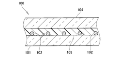
- the laminated glass with heating wire disclosed in Patent Document 1 is shown in FIGS.
- a laminated glass 100 with a heating wire as a windshield of a vehicle includes a lower glass plate 101, and a heating wire 102 that generates heat by being placed on the lower glass plate 101 and being energized.
- the intermediate film 103 made of polyvinyl butyral is placed on the heating wire 102 and the lower glass plate 101, and the upper glass plate 104 is placed on and bonded to the intermediate film 103.
- the heating wire 102 When the heating wire 102 is energized, the heating wire 102 generates heat. When the heating wire 102 generates heat, the lower glass plate 101 and the upper glass plate 104 are prevented from being fogged.
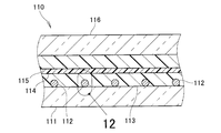
- a laminated glass 110 with a heating wire having a sound insulation function is composed of a lower glass plate 111, a heating wire 112 placed on the lower glass plate 111, and a lower adhesive covering the heating wire 112.
- an intermediate film sandwiched between functional layers 114 having a sound insulating function is used.
- the lower adhesive layer 113 is deformed by the cross-sectional area of the heating wire 112. Since the functional layer 114 is softer than the lower adhesive layer 113, the lower adhesive layer 113 is deformed so as to protrude toward the functional layer 114 side. It is considered that distortion occurs because a part 113a of the lower adhesive layer 113 protrudes toward the functional layer 114 side. Therefore, it is desired to provide a laminated glass with heating wire that does not cause distortion near the heating wire.
- An object of the present invention is to provide a laminated glass with heating wire that does not cause distortion in the vicinity of the heating wire.
- a laminated glass containing heating wires there is a laminated glass containing heating wires, and a functional layer, an upper adhesive layer and a lower adhesive layer placed on the upper and lower sides of the functional layer, and above and below the upper and lower adhesive layers. And a heating wire interposed between the lower adhesive layer and the lower glass plate, and the functional layer is softer than the lower adhesive layer.
- a raw material is used, and a lower limit value of the thickness of the lower adhesive layer is provided with a heating wire-containing laminated glass whose diameter is 19 times the diameter of the heating wire.
- the functional layer has a sound insulation function.
- the heating wire has a diameter of 15 ⁇ m to 25 ⁇ m.
- the lower adhesive layer, the functional layer, and the upper adhesive layer constitute an intermediate layer, and the thickness of the intermediate layer is 1.90 mm or less.
- the lower limit value of the thickness of the lower adhesive layer is 19 times the diameter of the heating wire.
- the heating wire is placed between the lower glass plate and the lower adhesive layer. Since the lower adhesive layer is softer than the lower glass plate, the lower adhesive layer is pressed by the heating wire. As a result, the upper surface (surface farther from the lower glass plate) of the lower adhesive layer rises locally and protrudes. The greater the protrusion height, the more significant the distortion.
- This protrusion height becomes more conspicuous as the thickness of the lower adhesive layer is smaller, and becomes gentler as the thickness is larger.
- the distortion was not acceptable, and when it was 19 times or more, the distortion was acceptable. That is, by setting it to 19 times or more, distortion that may occur in the vicinity of the heating wire can be sufficiently suppressed.
- the functional layer has a sound insulation function.
- the sound insulation function By having a sound insulation function, the quietness of a vehicle or a building in which laminated glass with heating wires is used can be improved.
- the diameter of the heating wire is preferably 15 ⁇ m to 25 ⁇ m. If it is too thin, sufficient heat energy cannot be obtained, and if it is too thick, the appearance deteriorates.
- the thickness of the intermediate layer is 1.90 mm or less, perspective distortion can be suppressed.
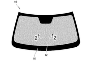
- FIG. 2 is an enlarged sectional view taken along line 2-2 in FIG.
- FIG. 3 is an enlarged view of region 3 in FIG. 2. It is the figure which showed the manufacturing method of the heating glass containing laminated glass by Example 1.
- FIG. It is a figure explaining the example of an experiment done about heating glass laminated glass. It is the figure shown about the distortion which may arise in the vicinity of a heating wire. It is the figure shown about the distortion which may arise when seeing through the laminated glass with a heating wire. It is the figure which showed the manufacturing method of the heating glass containing laminated glass by Example 2.
- FIG. It is sectional drawing of the laminated glass containing a heating wire which concerns on Example 2.
- FIG. is sectional drawing of the conventional laminated glass with a heating wire. It is sectional drawing shown about the problem of the conventional laminated glass with a heating wire. It is the figure which expanded the area
- the laminated glass 10 with heating wire according to Example 1 is used for a vehicle windshield. Details of the laminated glass 10 with heating wire will be described with reference to FIGS.
- the laminated glass 10 with heating wires is covered with a lower glass plate 11 disposed on the vehicle interior side, a plurality of heating wires 12 placed on the lower glass plate 11, and these heating wires 12.
- a lower adhesive layer 13 having adhesiveness, a functional layer 14 covering the lower adhesive layer 13 and having a sound insulation function, an upper adhesive layer 15 covering the functional layer 14 and having adhesiveness, and the upper adhesive layer 15 And an upper glass plate 16 placed on the substrate.
- the lower and upper glass plates 11 and 16 glass plates having a thickness of 2 mm can be used.
- the lower and upper glass plates 11 and 16 are so-called bi-directional bent glass that is bent in the vehicle width direction and also in the height direction.
- the upper glass plate 16 can be arranged on the vehicle compartment side, and either glass plate may be arranged on the vehicle compartment side.
- the material, thickness, and bending of the glass can be appropriately selected according to the application and function of the laminated glass 10 with heating wire. Details of the heating wire 12, the lower adhesive layer 13, the upper adhesive layer 15, and the functional layer 14 will be described with reference to FIG.
- the lower and upper adhesive layers 13 and 15 are both made of polyvinyl butyral.
- the thickness of the lower adhesive layer 13 is 0.58 mm, for example, and the thickness of the upper adhesive layer 15 is 0.2 mm.
- the functional layer 14 is a layer of polyvinyl butyral (Acoustic PVB, hereinafter referred to as “sound insulating polyvinyl butyral” as appropriate) having a sound insulation function with a thickness of 0.1 mm.
- the thickness of the lower adhesive layer 13 is desirably 0.39 mm or more. That is, it is desirable that the thickness of the lower adhesive layer 13 is 19 times or more with respect to the diameter of the heating wire 12.
- the sound insulating polyvinyl butyral used for the functional layer 14 is a softer material than the polyvinyl butyral used for the lower adhesive layer 13.
- the diameter of the heating wire 12 is preferably 15 ⁇ m to 25 ⁇ m, and more preferably 18 ⁇ m to 21 ⁇ m. If it is too thin, sufficient heat energy cannot be obtained, and if it is too thick, the appearance deteriorates.
- Polyvinyl butyral containing tin-doped indium oxide (ITO) can be used for the lower and upper adhesive layers 13 and 15. That is, if it is softer than the functional layer 14, the lower and upper adhesive layers 13 and 15 can be made of a material having a heat shielding function.
- the material of the heating wire 12 can also be appropriately selected according to the application and function. A method for producing the laminated glass 10 with heating wire will be described with reference to FIG.
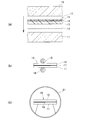
- the lower and upper adhesive layers 13 and 15 and the functional layer 14 are adhered to produce the intermediate film 17. Then, the heating wire 12, the intermediate film 17, and the upper glass plate 16 are placed on the lower glass plate 11 in this order.
- the heating wire 12 is connected to a bus bar or the like for energizing the heating wire 12. By raising and lowering the bus bar, the heating wire 12 can be raised and lowered integrally. By energizing the bus bar, the heating wire 12 can integrally generate heat.
- the lower and upper glass plates 16 are temporarily bonded to the intermediate film 17 by pressing with rollers 18 and 18 from the lower surface of the lower glass plate 11 and the upper surface of the upper glass plate 16.
- the A product obtained by temporary bonding is referred to as a temporary bonding body 19.
- Temporary bonding can be performed not only by such roller temporary bonding but also by vacuum bag temporary bonding or ring temporary bonding.
- the temporary adhesion body 19 is moved into the autoclave 21 to perform the main adhesion.
- the laminated glass 10 with heating wire FIG. 1
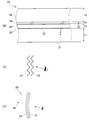
- a laminated glass 30 with heating wire used in the experiment is a heating wire using a lower glass plate 31 made of soda-lime-silica glass having a thickness t1 and a tungsten wire having a diameter d. 32, a lower adhesive layer 33 using polyvinyl butyral of thickness t2, a functional layer 34 using sound insulating polyvinyl butyral of thickness t3, an upper adhesive layer 35 using polyvinyl butyral of thickness t4, And an upper glass plate 36 using soda-lime-silica glass of t5.
- a plurality of laminated glass 30 with heating wires in which the thickness t2 of the lower adhesive layer 33 and the thickness t4 of the upper adhesive layer 35 are different, were created and tested. That is, the thickness t1 of the lower glass plate 31, the diameter d of the heating wire 32, the thickness t3 of the functional layer 34, and the thickness t5 of the upper glass plate 36 were set to the same value in all experiments.
- the material was not changed. That is, the lower and upper glass plates 31 and 36 are soda-lime-silica glass bent in both directions, a tungsten wire is used for the heating wire 32, a polyvinyl butyral is used for the lower and upper adhesive layers 33 and 35, and a functional layer. A sound insulating polyvinyl butyral was used for 34.
- the object 41 was looked through the produced laminated glass 30 with heating wire, and it was visually confirmed whether or not distortion occurred. If distortion does not occur, it is acceptable, and if distortion occurs, it is unacceptable. Details of the experiment thus performed will be described with reference to Table 1.
- Type of lower glass plate Soda lime silica glass Lower glass plate thickness t1: 2.0 mm
- Type of heating wire Tungsten Heating wire diameter d: 21.0 ⁇ m (0.021 mm)
- Type of lower adhesive layer Polyvinyl butyral Lower adhesive layer thickness t2: 0.33 mm
- Type of functional layer Sound insulating polyvinyl butyral Functional layer thickness t3: 0.1 mm
- Type of upper adhesive layer polyvinyl butyral Upper adhesive layer thickness t4: 0.33 mm
- Type of upper glass plate Soda lime silica glass Upper glass plate thickness t5: 2.0 mm
- Lower adhesive layer thickness t2 / heating wire diameter d 15.71
- Lower adhesive layer thickness t2 + functional layer thickness t3 + upper adhesive layer thickness t4 0.76 mm
- the thickness t2 of the lower adhesive layer was changed to 0.39 mm
- the thickness t4 of the upper adhesive layer was changed to 0.39 mm.
- t2 / d was 18.57
- t2 + t3 + t4 was 0.88 mm.
- the thickness t2 of the lower adhesive layer was changed to 0.58 mm
- the thickness t4 of the upper adhesive layer was changed to 0.20 mm.
- t2 / d was 27.62
- t2 + t3 + t4 was 0.88 mm.
- the thickness t2 of the lower adhesive layer was changed to 1.47 mm
- the thickness t4 of the upper adhesive layer was changed to 0.33 mm.
- t2 / d was 70.00
- t2 + t3 + t4 was 1.90 mm.
- the thickness t2 of the lower adhesive layer was changed to 2.23 mm.
- t4 is 0.33 mm, which is the same as the experiment number 4.
- t2 / d was 106.19, and t2 + t3 + t4 was 2.66 mm.
- the thickness t2 of the lower adhesive layer was changed to 0.33 mm
- the thickness t4 of the upper adhesive layer was changed to 0.71 mm.
- t2 / d was 15.71
- t2 + t3 + t4 was 1.14 mm.
- the diameter d of the heating wire 112 is 21.0 ⁇ m
- the thickness T2 of the lower adhesive layer 113 is 0.33 mm.
- the thickness T2 of the lower adhesive layer 113 is 15.71 times the diameter d of the heating wire 112.
- the lower adhesive layer 113 is deformed by the same area (d / 2) 2 ⁇ ⁇ of the heating wire 112. Since the functional layer 114 is softer than the lower adhesive layer 113, the lower adhesive layer 113 is deformed so as to protrude toward the functional layer 114. That is, the area S1 of the lower adhesive layer 113 protruding from the functional layer 114 is approximately (d / 2) 2 ⁇ ⁇ . In addition, the influence of the deformation caused by the heating wire 112 extends within the range of the angle ⁇ around the heating wire 112.
- the lower adhesive layer 113 protrudes toward the functional layer 114 by the height h1 at the maximum. It is considered that distortion occurs in the vicinity of the heating wire due to the large protruding amount.
- the diameter d of the heating wire 12 is 21.0 ⁇ m, and the minimum value of the thickness t2 of the lower adhesive layer 13 is 0.39 mm. It is.
- the thickness t ⁇ b> 2 of the lower adhesive layer 13 is 18.57 times the diameter of the heating wire 12.
- the influence of the heating wire 12 occurs in the range of the angle ⁇ .
- the thickness t2 of the lower adhesive layer 13 is larger than that of the comparative example, the width of the deformed portion is large. Since the width of the portion to be deformed is large, the protrusion height h2 that protrudes into the functional layer 14 when absorbing the deformation amount S2 ( ⁇ (d / 2) 2 ⁇ ⁇ ) may be low. Generation
- the thickness of the lower adhesive layer 13 is increased in order to prevent distortion in the vicinity of the heating wire 12. Generation of distortion in the vicinity of the heating wire 12 can be prevented by an easy means.
- the thickness t2 + t3 + t4 of the intermediate film was 2.66 mm.
- the thickness of the interlayer film was thick
- the distortion was within an allowable range. That is, the perspective distortion can be suppressed by setting the thickness of the intermediate film to 1.90 mm or less.
- the thickness of the lower adhesive layer is preferably 1.90 mm or less.
- FIG. 8 shows a method of manufacturing the laminated glass with heating wire of Example 2, and corresponds to FIG.
- an intermediate film 57 (first intermediate film 57) composed of a part 53a of the lower adhesive layer, a functional layer 54 and an upper adhesive layer 55, and a remaining part 53b (second intermediate film 53b) of the lower adhesive layer. ).
- the heating wire 12 On the lower glass plate 11, the heating wire 12, the remaining portion 53 b of the lower adhesive layer, the intermediate film 57, and the upper glass plate 16 are placed in this order, and temporary adhesion and adhesion are performed. Temporary adhesion and adhesion can be performed by the method described in FIGS. 4B and 4C.
- the lower adhesive layer (intermediate film) from two members, it is possible to produce a laminated glass with heating wire by using parts conventionally used. The cost of parts can be reduced, and the price of laminated glass with heating wires can also be reduced. For example, Sekisui Chemical Co., Ltd., Slek Sound Acoustic Film can be used for the intermediate film 17.
- the effect of the present invention can be obtained even with a laminated glass 50 with a heating wire in which the lower adhesive layer 53 is constituted by two intermediate films 57 and 53 b. That is, by setting the thickness of the lower adhesive layer 53 to 19 times or more the diameter of the heating wire 12, distortion that may occur in the vicinity of the heating wire 12 can be sufficiently suppressed.
- the laminated glass with heating wire according to the present invention is applied to the windshield of the vehicle in the embodiments, it can be applied to other vehicles such as trains and airplanes, and can be applied to architectural window glass.
- the application is not limited.
- the heating glass-containing laminated glass of the present invention is suitable for a windshield of an automobile.
Landscapes
- Joining Of Glass To Other Materials (AREA)
Abstract
電熱線(12)の近傍で歪みが生じない電熱線入り合せガラス(10)が開示される。電熱線入り合せガラス(10)は、下面および上面に下接着層(13)および上接着層(15)が積層された遮音機能を備えた機能層(14)を備えている。機能層(14)は、下接着層(13)よりも柔らかい素材が用いられる。下接着層(13)の厚さの下限値は、電熱線(12)の直径の19倍である。
Description
本発明は、中間膜とガラス板との間に電熱線を介在させた電熱線入り合せガラスに関する。
ガラス板に電熱線を載せた状態で中間膜を被せ、この中間膜の上方からさらにガラス板を被せた、電熱線入り合せガラスが知られている(例えば、特許文献1)。特許文献1に開示されている電熱線入り合せガラスは、図10~図12に示されている。
図10を参照するに、車両のフロントガラスとしての電熱線入り合せガラス100は、下側ガラス板101と、この下側ガラス板101に複数載せられ通電されることで熱を発する電熱線102と、この電熱線102及び下側ガラス板101に被せられるポリビニルブチラール製の中間膜103と、この中間膜103に載せられ接着される上側ガラス板104とからなる。
電熱線102に通電することで電熱線102が発熱する。電熱線102が発熱することで、下側ガラス板101及び上側ガラス板104に曇りが生じることを防止する。
近年、さらに機能性を高めた電熱線入り合せガラスが種々提案されている。このような機能性の高められた電熱線入り合せガラスについて詳細を図11で説明する。
図11に示すように、遮音機能を有する電熱線入り合せガラス110は、下側ガラス板111と、この下側ガラス板111に載せられる電熱線112と、この電熱線112に被せられる下側接着層113と、この下側接着層113に載せられ遮音機能を有する機能層114と、この機能層114に被せられる上側接着層115と、この上側接着層115に被せられる上側ガラス板116とからなる。即ち、遮音機能を有する機能層114の挟み込まれた中間膜が用いられるようになった。機能層114が挟み込まれることで、車室内の静粛性を高めることができる。
しかし、このような電熱線入り合せガラス110について、本発明者らが観察を行ったところ、電熱線112の近傍で歪みが生じ得ることが分かった。歪みが生じる理由について図12で説明する。
図12に示すように、電熱線112に下側接着層113を被せることにより、電熱線112の断面積の分だけ下側接着層113が変形する。機能層114が下側接着層113よりも柔らかいことにより、下側接着層113は機能層114側に向かって突出するように変形する。機能層114側に向かって下側接着層113の一部113aが突出することで、歪みが生じているものと考えられる。そこで、電熱線の近傍で歪みが生じない電熱線入り合せガラスの提供が望まれる。
本発明の課題は、電熱線の近傍で歪みが生じない電熱線入り合せガラスを提供することにある。
請求項1に係る発明によれば、電熱線入り合せガラスであって、機能層と、前記機能層の上下に被せられた上接着層及び下接着層と、前記上及び下接着層の上下に被せられた上ガラス板及び下ガラス板と、前記下接着層と前記下ガラス板との間に介在された電熱線と、を具備しており、前記機能層は、前記下接着層よりも柔らかい素材が用いられ、前記下接着層の厚さの下限値は、前記電熱線の直径の19倍である電熱線入り合せガラスが提供される。
請求項2に係るでは、好ましくは、前記機能層は、遮音機能を有する。
請求項3に係る発明では、好ましくは、前記電熱線の前記直径は、15μm~25μmである。
請求項4に係る発明では、好ましくは、前記下接着層、前記機能層および前記上接着層は、中間層を構成し、前記中間層の厚みは、1.90mm以下である。
請求項1に係る発明では、下側接着層の厚さの下限値は、電熱線の直径の19倍である。電熱線は下ガラス板と下接着層との間に置かれる。下ガラス板に比較して下接着層が柔らかいため、電熱線により下接着層が押される。その結果、下接着層の上面(下側ガラス板から遠い方の面)が局部的に盛り上がり突出する。この突出高さが大きいほど歪みが著しくなる。
この突出高さは、下接着層の厚さが小さい程顕著になり、厚さが大きいほど穏やかになる。実験の結果、下接着層の厚さが電熱線の19倍未満であると、歪みが許容できず、19倍以上であれば歪みが許容できることが確認できた。即ち、19倍以上に設定することで、電熱線の近傍で生じ得る歪みを十分に抑制することができる。
請求項2に係る発明では、機能層は遮音機能を有する。遮音機能を有することで、電熱線入り合せガラスが用いられる、車両や建築物の静粛性を高めることができる。
請求項3に係る発明では、電熱線の直径は、好ましくは、15μm~25μmである。細すぎると十分な熱エネルギを得ることができず、太すぎると外観性が低下する。
請求項4に係る発明では、中間層の厚みは、1.90mm以下であるため、透視歪みを抑制することができる。
以下、本発明の好ましい幾つかの実施例について、添付した図面に基づいて詳細に説明する。
図1に示されるように、実施例1による電熱線入り合せガラス10は、車両用フロントガラスに用いられる。このような電熱線入り合せガラス10の詳細を図2~図7に基づいて説明する。
図2に示すように、電熱線入り合せガラス10は、車室側に配置される下ガラス板11と、この下ガラス板11に複数載せられた電熱線12と、これらの電熱線12に被せられ接着性を有する下接着層13と、この下接着層13に被せられ遮音機能を有する機能層14と、この機能層14に被せられ接着性を有する上接着層15と、この上接着層15に載せられる上ガラス板16とからなる。
下及び上ガラス板11,16には、厚さ2mmのガラス板を用いることができる。また、下及び上ガラス板11,16は、車幅方向に曲げられていると共に、高さ方向にも曲げられている、いわゆる双方向曲げガラスが用いられる。
上ガラス板16を車室側に配置することもでき、どちらのガラス板を車室側に配置してもよい。ガラスの素材、厚さ及び曲げは、電熱線入り合せガラス10の用途や機能に合わせて適宜選択することができる。電熱線12、下接着層13、上接着層15、及び機能層14についての詳細は図3で説明する。
図3に示すように、下ガラス板11に載せられている電熱線12には、直径21μmのタングステン線が用いられる。下及び上接着層13,15は、共にポリビニルブチラールを用いられ、下接着層13の厚さは、例えば、0.58mm、上接着層15の厚さは0.2mmである。機能層14は、厚さ0.1mmの遮音機能を持たせたポリビニルブチラール(Acoustic PVB、以下、適宜「遮音性ポリビニルブチラール」という。)の層である。
電熱線12の直径が21μm(0.021mm)である場合に、下接着層13の厚さは、0.39mm以上であることが望ましい。即ち、電熱線12の直径に対して、下接着層13の厚さは、19倍以上であることが望ましい。
機能層14に用いられる遮音性ポリビニルブチラールは、下接着層13に用いられるポリビニルブチラールよりも柔らかい素材である。電熱線12の直径は、15μm~25μmであることが好ましく、18μm~21μmであることが望ましい。細すぎると十分な熱エネルギを得ることができず、太すぎると外観性が低下するからである。
下及び上接着層13,15に錫ドープ酸化インジウム(ITO)を含有したポリビニルブチラールを用いることもできる。即ち、機能層14よりも柔らかければ、下及び上接着層13,15に遮熱の機能等を有した素材を用いることもできる。電熱線12の素材についても用途や機能に合わせて適宜選択することができる。電熱線入り合せガラス10の製造方法について図4で説明する。
図4(a)に示すように、合せガラスの製造に先立って、下及び上接着層13,15及び機能層14を接着させ、中間膜17を製造しておく。そして、下ガラス板11上に電熱線12、中間膜17、上ガラス板16の順に載置する。
電熱線12は、電熱線12に通電をするためのバスバー等に接続されている。バスバーを昇降させることにより、電熱線12を一体的に昇降させることができる。バスバーに通電させることで、電熱線12を一体的に発熱させることができる。
図4(b)に示すように、下ガラス板11の下面及び上ガラス板16の上面からローラ18,18を用いて押圧することにより、下及び上ガラス板16が中間膜17に仮接着される。仮接着されて得られた物を仮接着体19とする。仮接着は、このようなローラ仮接着の他、真空バッグ仮接着やリング仮接着によっても行うことができる。
図4(c)に示すように、仮接着体19をオートクレーブ21内に移動させ、本接着を行う。本接着を行うことで電熱線入り合せガラス10(図1)を得ることができる。このようにして得ることのできる電熱線入り合せガラスについて実験を行った。詳細を図5~図7で説明する。
(実験例)
本発明に係る実験例を以下に述べる。なお、本発明は実験例に限定されるものではない。
本発明に係る実験例を以下に述べる。なお、本発明は実験例に限定されるものではない。
図5(a)に示すように、実験に用いられた電熱線入り合せガラス30は、厚さt1のソーダ石灰シリカガラスを用いた下ガラス板31と、直径dのタングステン線を用いた電熱線32と、厚さt2のポリビニルブチラールを用いた下接着層33と、厚さt3の遮音性ポリビニルブチラールを用いた機能層34と、厚さt4のポリビニルブチラールを用いた上接着層35と、厚さt5のソーダ石灰シリカガラスを用いた上ガラス板36とからなる。
下接着層33の厚さt2及び上接着層35の厚さt4が異なる、複数の電熱線入り合せガラス30を作成し、実験を行った。即ち、下ガラス板31の厚さt1、電熱線32の直径d、機能層34の厚さt3、上側ガラス板36の厚さt5については、全ての実験において同じ値とした。
全ての実験において、素材の変更は行わなかった。即ち、下及び上ガラス板31,36は、双方向に曲げられたソーダ石灰シリカガラスであり、電熱線32にタングステン線を用い、下及び上接着層33,35にポリビニルブチラールを用い、機能層34に遮音性ポリビニルブチラールを用いた。
図5(b)に示すように、作成した電熱線入り合せガラス30について、電熱線32の近傍で歪みが生じているか否かを目で確認した。歪みが生じていなければ合格であり、歪みが生じていれば不合格である。
図5(c)に示すように、作成した電熱線入り合せガラス30を介して物41を覗き、歪みが生じているか否かを目で確認した。歪みが生じていなければ合格であり、歪みが生じていれば不合格である。このようにして行った実験について詳細を表1に沿って説明する。

実験番号1では、以下の条件で実験を行った。
下ガラス板の種類: ソーダ石灰シリカガラス
下ガラス板の厚さt1: 2.0mm
電熱線の種類: タングステン
電熱線の直径d: 21.0μm(0.021mm)
下接着層の種類: ポリビニルブチラール
下接着層の厚さt2: 0.33mm
機能層の種類: 遮音性ポリビニルブチラール
機能層の厚さt3: 0.1mm
上接着層の種類: ポリビニルブチラール
上接着層の厚さt4: 0.33mm
上ガラス板の種類: ソーダ石灰シリカガラス
上ガラス板の厚さt5: 2.0mm
下接着層の厚さt2/電熱線の直径d: 15.71
下接着層の厚さt2+機能層の厚さt3+上接着層の厚さt4: 0.76mm
下ガラス板の種類: ソーダ石灰シリカガラス
下ガラス板の厚さt1: 2.0mm
電熱線の種類: タングステン
電熱線の直径d: 21.0μm(0.021mm)
下接着層の種類: ポリビニルブチラール
下接着層の厚さt2: 0.33mm
機能層の種類: 遮音性ポリビニルブチラール
機能層の厚さt3: 0.1mm
上接着層の種類: ポリビニルブチラール
上接着層の厚さt4: 0.33mm
上ガラス板の種類: ソーダ石灰シリカガラス
上ガラス板の厚さt5: 2.0mm
下接着層の厚さt2/電熱線の直径d: 15.71
下接着層の厚さt2+機能層の厚さt3+上接着層の厚さt4: 0.76mm
以上のような条件で行った実験番号1では、電熱線の近傍で歪みが生じた。電熱線の近傍で歪みが生じたので、不合格を示す×である。一方、電熱線入り合せガラスを介して目視した場合の歪み、即ち、合せガラス全体の歪みは生じなかった。全体の歪みは生じなかったので、合格を示す○である。
実験番号2では、下接着層の厚さt2を0.39mm、上接着層の厚さt4を0.39mmに変更した。t2/dは、18.57であり、t2+t3+t4は0.88mmであった。
以上のような条件で行った実験番号2では、電熱線による歪みが生じなかったので○であり、全体の歪みも生じなかったので○である。
実験番号3では、下接着層の厚さt2を0.58mm、上接着層の厚さt4を0.20mmに変更した。t2/dは、27.62であり、t2+t3+t4は0.88mmであった。
以上のような条件で行った実験番号3では、電熱線による歪みが生じなかったので○であり、全体の歪みも生じなかったので○である。
実験番号4では、下接着層の厚さt2を1.47mm、上接着層の厚さt4を0.33mmに変更した。t2/dは、70.00であり、t2+t3+t4は1.90mmであった。
以上のような条件で行った実験番号4では、電熱線による歪みが生じなかったので○であり、全体の歪みも生じなかったので○である。
実験番号5では、下接着層の厚さt2を2.23mmに変更した。t4は、0.33mmで実験番号4と同じである。t2/dは、106.19であり、t2+t3+t4は2.66mmであった。
以上のような条件で行った実験番号5では、電熱線による歪みが生じなかったので○であった。しかし、全体の歪みが生じたので×である。
実験番号6では、下接着層の厚さt2を0.33mm、上接着層の厚さt4を0.71mmに変更した。t2/dは、15.71であり、t2+t3+t4は1.14mmであった。
以上のような条件で行った実験番号6では、電熱線による歪みが生じたので×であった。しかし、全体の歪みは生じなかったので○である。このような結果になった理由について図6、図7で説明する。
図6(a)に示すように、比較例に係る電熱線入り合せガラス110は、電熱線112の直径dが21.0μmであり、下接着層113の厚さT2が0.33mmである。下接着層113の厚さT2は、電熱線112の直径dに対して、15.71倍である。
電熱線112に下接着層113を被せることで、電熱線112の面積(d/2)2×πと同じだけ下接着層113が変形する。下接着層113よりも機能層114が柔らかいため、下接着層113は機能層114に向かって突出するように変形する。即ち、機能層114に突出している下接着層113の面積S1≒(d/2)2×πである。また、電熱線112による変形の影響は、電熱線112を中心とした角度θの範囲内に及ぶ。角度θの範囲で、S1の変形量を吸収することで、下接着層113は最大で高さh1だけ機能層114に向かって突出する。この突出量が大きいことで、電熱線近傍に歪みが生じるものと考えられる。
このことは、以下のように言い換えることもできる。下接着層113の厚さT2が、電熱線112の直径dに対して、18.57倍未満である比較例では、下接着層113の下部に配置される電熱線112と、下接着層113の上面に配置される機能層114との距離が近い。電熱線入り合せガラス110は、電熱線112の影響で、下接着層113の一部が機能層114に向かって突出する。下接着層113と機能層114とが近い場合は、下接着層113が機能層114に向かって突出する、突出高さh1が高い。突出高さh1が高いことで、電熱線112の近傍で歪みが生ずる。
図6(b)に示すように、実施例に係る電熱線入り合せガラス10は、電熱線12の直径dが21.0μmであり、下接着層13の厚さt2の最小値が0.39mmである。下接着層13の厚さt2は、電熱線12の直径に対して、18.57倍である。
実施例の場合においても、角度θの範囲で電熱線12の影響が生じるものと考えられる。しかし、比較例に比べて、下接着層13の厚さt2が大きいことで、変形する部位の幅が大きい。変形する部位の幅が大きいため、変形量S2(≒(d/2)2×π)を吸収する際に機能層14に突出する突出高さh2が低くて済む。突出高さh2が低いことで、電熱線近傍で生じ得る歪みの発生を抑制することができる。即ち、下接着層13の厚さt2の下限値を、電熱線12の直径dの18.57倍に設定することで、電熱線12の近傍で生じ得る歪みを十分に抑制することができる。本発明によれば、電熱線12近傍での歪みを防ぐために、下接着層13の厚さを厚くした。容易な手段により電熱線12近傍での歪みの発生を防ぐことができる。
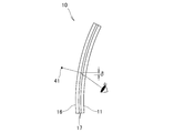
図7に示すように、電熱線入り合せガラス10を介して物41を見た場合に、下ガラス板11、中間膜17及び上ガラス板16のそれぞれで光が屈折する。中間膜17が厚いことで、変位量δが大きくなり、許容できる範囲を超えた歪みが生じる。
前述の実験番号5では、中間膜(下側接着層+機能層+上側接着層)の厚みt2+t3+t4を2.66mmとした。中間膜の厚さが厚い実験番号5では、許容できる範囲を超えた歪みが生じた。一方、中間膜の厚みが1.90mmであった実験番号4では、歪みが許容できる範囲内であった。即ち、中間膜の厚さを1.90mm以下とすることで、透視歪みを抑制することができる。
以上をまとめると、電熱線による歪みを防ぐという観点からは、下接着層の厚みの値の下限値を電熱線の直径の19倍に設定することが好ましく、さらに透視歪みを抑制するには、下接着層と、機能層と、上接着層とからなる中間膜の厚みを1.90mm以下とすることが望ましい。
次に、本発明の実施例2を図面に基づいて説明する。図8は実施例2の電熱線入り合せガラスの製造方法を示し、図4(a)に対応している。
図8に示されるように、下接着層の一部53a、機能層54及び上接着層55からなる中間膜57(第1中間膜57)と、下接着層の残部53b(第2中間膜53b)とを用いる。
下ガラス板11に、電熱線12、下接着層の残部53b、中間膜57、上ガラス板16の順に載せ、仮接着及び接着を行う。仮接着及び接着については、図4(b)及び図4(c)で説明した方法により行うことができる。
下接着層(中間膜)を2つの部材から構成することで、従来から用いられている部品により、電熱線入り合せガラスを製造することができる。部品のコストを下げることができ、電熱線入り合せガラスの価格も低下させることができる。例えば、中間膜17には、積水化学工業株式会社製、エスレック・サウンドアコースティックフィルムを用いることができる。
図9に示すように、2つの中間膜57,53bで下接着層53を構成した電熱線入り合せガラス50であっても、本発明の効果を得ることができる。即ち、下側接着層53の厚さを、電熱線12の直径の19倍以上に設定することで、電熱線12の近傍で生じ得る歪みを十分に抑制することができる。
本発明に係る電熱線入り合せガラスは、実施例では車両のフロントガラスに適用したが、電車や飛行機等他の乗り物に適用することや、建築用窓ガラスに適用することもでき、これらのものに用途は限定されない。
本発明の電熱線入り合せガラスは、四輪車のフロントガラスに好適である。
10,50…電熱線入り合せガラス、11…下ガラス板、12…電熱線、13,53…下接着層、14,54…機能層、15,55…上接着層、16…上ガラス板、17…中間層。
Claims (4)
- 機能層と、
前記機能層の上下に被せられた上接着層及び下接着層と、
前記上及び下接着層の上下に被せられた上ガラス板及び下ガラス板と、
前記下接着層と前記下ガラス板との間に介在された電熱線と、
を具備する電熱線入り合せガラスにおいて、
前記機能層は、前記下接着層よりも柔らかい素材が用いられ、
前記下接着層の厚さの下限値は、前記電熱線の直径の19倍であることを特徴とする電熱線入り合せガラス。 - 前記機能層は、遮音機能を有する、請求項1に記載の電熱線入り合せガラス。
- 前記電熱線の前記直径は、15μm~25μmである、請求項1に記載の電熱線入り合せガラス。
- 前記下接着層、前記機能層および前記上接着層は、中間層を構成し、前記中間層の厚みは、1.90mm以下である、請求項1に記載の電熱線入り合せガラス。
Applications Claiming Priority (2)
| Application Number | Priority Date | Filing Date | Title |
|---|---|---|---|
| JP2011197039A JP2013056811A (ja) | 2011-09-09 | 2011-09-09 | 電熱線入り合せガラス |
| JP2011-197039 | 2011-09-09 |
Publications (1)
| Publication Number | Publication Date |
|---|---|
| WO2013035778A1 true WO2013035778A1 (ja) | 2013-03-14 |
Family
ID=47832219
Family Applications (1)
| Application Number | Title | Priority Date | Filing Date |
|---|---|---|---|
| PCT/JP2012/072717 Ceased WO2013035778A1 (ja) | 2011-09-09 | 2012-09-06 | 電熱線入り合せガラス |
Country Status (2)
| Country | Link |
|---|---|
| JP (1) | JP2013056811A (ja) |
| WO (1) | WO2013035778A1 (ja) |
Cited By (2)
| Publication number | Priority date | Publication date | Assignee | Title |
|---|---|---|---|---|
| WO2018134608A1 (en) * | 2017-01-20 | 2018-07-26 | Pilkington Group Limited | Laminated glass and method of manufacturing the same |
| WO2023227444A1 (de) | 2022-05-24 | 2023-11-30 | Saint-Gobain Glass France | Beheizbare verbundscheibe mit akustisch dämpfenden eigenschaften |
Families Citing this family (9)
| Publication number | Priority date | Publication date | Assignee | Title |
|---|---|---|---|---|
| US10912155B2 (en) | 2014-11-17 | 2021-02-02 | Dai Nippon Printing Co., Ltd. | Heating plate, conductive pattern sheet, vehicle, and method of manufacturing heating plate |
| EP3656749B1 (en) | 2014-11-17 | 2021-11-17 | Dai Nippon Printing Co., Ltd. | Heating plate, conductive pattern sheet, vehicle, and method of manufacturing heating plate |
| WO2016129699A1 (ja) * | 2015-02-13 | 2016-08-18 | 日本板硝子株式会社 | ウインドシールド |
| WO2017086381A1 (ja) | 2015-11-17 | 2017-05-26 | 大日本印刷株式会社 | 加熱電極装置、通電加熱ガラス、発熱板、乗り物、建築物用窓、導電体付きシート、導電性パターンシート、導電性発熱体、合わせガラスおよび導電性発熱体の製造方法 |
| JP6834176B2 (ja) * | 2016-05-26 | 2021-02-24 | 大日本印刷株式会社 | 加熱電極装置、通電加熱パネル |
| WO2018029995A1 (ja) * | 2016-08-12 | 2018-02-15 | 旭硝子株式会社 | 合わせガラス |
| CN110494283B (zh) | 2017-03-27 | 2022-04-05 | 株式会社可乐丽 | 夹层玻璃用的聚乙烯醇缩醛树脂薄膜 |
| WO2018181389A1 (ja) | 2017-03-27 | 2018-10-04 | 株式会社クラレ | 合わせガラス用のポリビニルアセタール樹脂フィルム |
| WO2019203349A1 (ja) | 2018-04-19 | 2019-10-24 | 株式会社クラレ | ポリビニルアセタール樹脂フィルム |
Citations (5)
| Publication number | Priority date | Publication date | Assignee | Title |
|---|---|---|---|---|
| JPH0872674A (ja) * | 1994-07-08 | 1996-03-19 | Asahi Glass Co Ltd | 電熱窓ガラス |
| JP2002057518A (ja) * | 2000-04-13 | 2002-02-22 | Saint-Gobain Glass France | 積層ペイン |
| JP2006523601A (ja) * | 2003-03-21 | 2006-10-19 | ピルキントン イタリア ソシエタ ペル アチオニ | 車輌用積層グレイジング |
| JP2008511529A (ja) * | 2004-08-31 | 2008-04-17 | サン−ゴバン グラス フランス | 赤外線および/または太陽光線を反射する薄膜積層体および加熱手段を備えた積層板ガラス |
| WO2008111388A1 (ja) * | 2007-03-14 | 2008-09-18 | Nippon Sheet Glass Company, Limited | 導電膜を有する合わせガラス、および合わせガラス用中間膜 |
-
2011
- 2011-09-09 JP JP2011197039A patent/JP2013056811A/ja not_active Withdrawn
-
2012
- 2012-09-06 WO PCT/JP2012/072717 patent/WO2013035778A1/ja not_active Ceased
Patent Citations (5)
| Publication number | Priority date | Publication date | Assignee | Title |
|---|---|---|---|---|
| JPH0872674A (ja) * | 1994-07-08 | 1996-03-19 | Asahi Glass Co Ltd | 電熱窓ガラス |
| JP2002057518A (ja) * | 2000-04-13 | 2002-02-22 | Saint-Gobain Glass France | 積層ペイン |
| JP2006523601A (ja) * | 2003-03-21 | 2006-10-19 | ピルキントン イタリア ソシエタ ペル アチオニ | 車輌用積層グレイジング |
| JP2008511529A (ja) * | 2004-08-31 | 2008-04-17 | サン−ゴバン グラス フランス | 赤外線および/または太陽光線を反射する薄膜積層体および加熱手段を備えた積層板ガラス |
| WO2008111388A1 (ja) * | 2007-03-14 | 2008-09-18 | Nippon Sheet Glass Company, Limited | 導電膜を有する合わせガラス、および合わせガラス用中間膜 |
Cited By (3)
| Publication number | Priority date | Publication date | Assignee | Title |
|---|---|---|---|---|
| WO2018134608A1 (en) * | 2017-01-20 | 2018-07-26 | Pilkington Group Limited | Laminated glass and method of manufacturing the same |
| US11559969B2 (en) | 2017-01-20 | 2023-01-24 | Pilkington Group Limited | Laminated glass and method of manufacturing the same |
| WO2023227444A1 (de) | 2022-05-24 | 2023-11-30 | Saint-Gobain Glass France | Beheizbare verbundscheibe mit akustisch dämpfenden eigenschaften |
Also Published As
| Publication number | Publication date |
|---|---|
| JP2013056811A (ja) | 2013-03-28 |
Similar Documents
| Publication | Publication Date | Title |
|---|---|---|
| JP2013056811A (ja) | 電熱線入り合せガラス | |
| CN112218837B (zh) | 夹层玻璃 | |
| JP7192862B2 (ja) | ガラス | |
| JP6905831B2 (ja) | 合わせガラス | |
| JP6807186B2 (ja) | サイドガラス | |
| JP6612989B2 (ja) | ヘッドアップディスプレイのための導電性コーティングを有している複合ペイン | |
| JP7044791B2 (ja) | 合わせガラスとその製造方法 | |
| JP7196922B2 (ja) | 合わせガラス | |
| US12459239B2 (en) | Laminated glass | |
| JP7262444B2 (ja) | 車両用窓ガラス及びその製造方法 | |
| JP7156298B2 (ja) | 合わせガラス | |
| CN113518765A (zh) | 夹层玻璃 | |
| WO2017204291A1 (ja) | 合わせガラス | |
| JP2019172512A (ja) | 合わせガラス | |
| WO2010093023A1 (ja) | 合わせガラス | |
| JP2019167275A (ja) | 合わせガラス | |
| CN106103377B (zh) | 窗用层叠基板具备窗用层叠基板的汽车以及窗用层叠基板用中间层结构体 | |
| JP6736448B2 (ja) | 合わせガラス | |
| WO2018029995A1 (ja) | 合わせガラス | |
| JP2007290549A (ja) | 車両用合わせガラス及びその製造方法 | |
| CN112203846A (zh) | 具有阶梯形功能部分的层压玻璃 | |
| JP7401781B2 (ja) | 車両用軽量合わせガラス板の製造方法 | |
| JP2022177338A (ja) | 合わせガラス | |
| CN212433741U (zh) | 触摸屏的贴合结构 | |
| WO2022270634A1 (ja) | ウインドシールド |
Legal Events
| Date | Code | Title | Description |
|---|---|---|---|
| 121 | Ep: the epo has been informed by wipo that ep was designated in this application |
Ref document number: 12829747 Country of ref document: EP Kind code of ref document: A1 |
|
| NENP | Non-entry into the national phase |
Ref country code: DE |
|
| 122 | Ep: pct application non-entry in european phase |
Ref document number: 12829747 Country of ref document: EP Kind code of ref document: A1 |