WO2013035864A1 - 弁付きステント、弁付きステント形成用基材、及び弁付きステントの生産方法 - Google Patents
弁付きステント、弁付きステント形成用基材、及び弁付きステントの生産方法 Download PDFInfo
- Publication number
- WO2013035864A1 WO2013035864A1 PCT/JP2012/072980 JP2012072980W WO2013035864A1 WO 2013035864 A1 WO2013035864 A1 WO 2013035864A1 JP 2012072980 W JP2012072980 W JP 2012072980W WO 2013035864 A1 WO2013035864 A1 WO 2013035864A1
- Authority
- WO
- WIPO (PCT)
- Prior art keywords
- stent
- forming
- base material
- valve
- cover
- Prior art date
- Legal status (The legal status is an assumption and is not a legal conclusion. Google has not performed a legal analysis and makes no representation as to the accuracy of the status listed.)
- Ceased
Links
Images














Classifications
-
- A—HUMAN NECESSITIES
- A61—MEDICAL OR VETERINARY SCIENCE; HYGIENE
- A61F—FILTERS IMPLANTABLE INTO BLOOD VESSELS; PROSTHESES; DEVICES PROVIDING PATENCY TO, OR PREVENTING COLLAPSING OF, TUBULAR STRUCTURES OF THE BODY, e.g. STENTS; ORTHOPAEDIC, NURSING OR CONTRACEPTIVE DEVICES; FOMENTATION; TREATMENT OR PROTECTION OF EYES OR EARS; BANDAGES, DRESSINGS OR ABSORBENT PADS; FIRST-AID KITS
- A61F2/00—Filters implantable into blood vessels; Prostheses, i.e. artificial substitutes or replacements for parts of the body; Appliances for connecting them with the body; Devices providing patency to, or preventing collapsing of, tubular structures of the body, e.g. stents
- A61F2/02—Prostheses implantable into the body
- A61F2/24—Heart valves ; Vascular valves, e.g. venous valves; Heart implants, e.g. passive devices for improving the function of the native valve or the heart muscle; Transmyocardial revascularisation [TMR] devices; Valves implantable in the body
- A61F2/2412—Heart valves ; Vascular valves, e.g. venous valves; Heart implants, e.g. passive devices for improving the function of the native valve or the heart muscle; Transmyocardial revascularisation [TMR] devices; Valves implantable in the body with soft flexible valve members, e.g. tissue valves shaped like natural valves
- A61F2/2415—Manufacturing methods
-
- A—HUMAN NECESSITIES
- A61—MEDICAL OR VETERINARY SCIENCE; HYGIENE
- A61F—FILTERS IMPLANTABLE INTO BLOOD VESSELS; PROSTHESES; DEVICES PROVIDING PATENCY TO, OR PREVENTING COLLAPSING OF, TUBULAR STRUCTURES OF THE BODY, e.g. STENTS; ORTHOPAEDIC, NURSING OR CONTRACEPTIVE DEVICES; FOMENTATION; TREATMENT OR PROTECTION OF EYES OR EARS; BANDAGES, DRESSINGS OR ABSORBENT PADS; FIRST-AID KITS
- A61F2/00—Filters implantable into blood vessels; Prostheses, i.e. artificial substitutes or replacements for parts of the body; Appliances for connecting them with the body; Devices providing patency to, or preventing collapsing of, tubular structures of the body, e.g. stents
- A61F2/02—Prostheses implantable into the body
- A61F2/04—Hollow or tubular parts of organs, e.g. bladders, tracheae, bronchi or bile ducts
- A61F2/06—Blood vessels
- A61F2/07—Stent-grafts
-
- A—HUMAN NECESSITIES
- A61—MEDICAL OR VETERINARY SCIENCE; HYGIENE
- A61F—FILTERS IMPLANTABLE INTO BLOOD VESSELS; PROSTHESES; DEVICES PROVIDING PATENCY TO, OR PREVENTING COLLAPSING OF, TUBULAR STRUCTURES OF THE BODY, e.g. STENTS; ORTHOPAEDIC, NURSING OR CONTRACEPTIVE DEVICES; FOMENTATION; TREATMENT OR PROTECTION OF EYES OR EARS; BANDAGES, DRESSINGS OR ABSORBENT PADS; FIRST-AID KITS
- A61F2/00—Filters implantable into blood vessels; Prostheses, i.e. artificial substitutes or replacements for parts of the body; Appliances for connecting them with the body; Devices providing patency to, or preventing collapsing of, tubular structures of the body, e.g. stents
- A61F2/02—Prostheses implantable into the body
- A61F2/24—Heart valves ; Vascular valves, e.g. venous valves; Heart implants, e.g. passive devices for improving the function of the native valve or the heart muscle; Transmyocardial revascularisation [TMR] devices; Valves implantable in the body
- A61F2/2412—Heart valves ; Vascular valves, e.g. venous valves; Heart implants, e.g. passive devices for improving the function of the native valve or the heart muscle; Transmyocardial revascularisation [TMR] devices; Valves implantable in the body with soft flexible valve members, e.g. tissue valves shaped like natural valves
-
- A—HUMAN NECESSITIES
- A61—MEDICAL OR VETERINARY SCIENCE; HYGIENE
- A61F—FILTERS IMPLANTABLE INTO BLOOD VESSELS; PROSTHESES; DEVICES PROVIDING PATENCY TO, OR PREVENTING COLLAPSING OF, TUBULAR STRUCTURES OF THE BODY, e.g. STENTS; ORTHOPAEDIC, NURSING OR CONTRACEPTIVE DEVICES; FOMENTATION; TREATMENT OR PROTECTION OF EYES OR EARS; BANDAGES, DRESSINGS OR ABSORBENT PADS; FIRST-AID KITS
- A61F2/00—Filters implantable into blood vessels; Prostheses, i.e. artificial substitutes or replacements for parts of the body; Appliances for connecting them with the body; Devices providing patency to, or preventing collapsing of, tubular structures of the body, e.g. stents
- A61F2/02—Prostheses implantable into the body
- A61F2/24—Heart valves ; Vascular valves, e.g. venous valves; Heart implants, e.g. passive devices for improving the function of the native valve or the heart muscle; Transmyocardial revascularisation [TMR] devices; Valves implantable in the body
- A61F2/2412—Heart valves ; Vascular valves, e.g. venous valves; Heart implants, e.g. passive devices for improving the function of the native valve or the heart muscle; Transmyocardial revascularisation [TMR] devices; Valves implantable in the body with soft flexible valve members, e.g. tissue valves shaped like natural valves
- A61F2/2418—Scaffolds therefor, e.g. support stents
-
- B—PERFORMING OPERATIONS; TRANSPORTING
- B32—LAYERED PRODUCTS
- B32B—LAYERED PRODUCTS, i.e. PRODUCTS BUILT-UP OF STRATA OF FLAT OR NON-FLAT, e.g. CELLULAR OR HONEYCOMB, FORM
- B32B1/00—Layered products having a non-planar shape
-
- A—HUMAN NECESSITIES
- A61—MEDICAL OR VETERINARY SCIENCE; HYGIENE
- A61F—FILTERS IMPLANTABLE INTO BLOOD VESSELS; PROSTHESES; DEVICES PROVIDING PATENCY TO, OR PREVENTING COLLAPSING OF, TUBULAR STRUCTURES OF THE BODY, e.g. STENTS; ORTHOPAEDIC, NURSING OR CONTRACEPTIVE DEVICES; FOMENTATION; TREATMENT OR PROTECTION OF EYES OR EARS; BANDAGES, DRESSINGS OR ABSORBENT PADS; FIRST-AID KITS
- A61F2/00—Filters implantable into blood vessels; Prostheses, i.e. artificial substitutes or replacements for parts of the body; Appliances for connecting them with the body; Devices providing patency to, or preventing collapsing of, tubular structures of the body, e.g. stents
- A61F2/02—Prostheses implantable into the body
- A61F2/24—Heart valves ; Vascular valves, e.g. venous valves; Heart implants, e.g. passive devices for improving the function of the native valve or the heart muscle; Transmyocardial revascularisation [TMR] devices; Valves implantable in the body
- A61F2/2475—Venous valves
-
- A—HUMAN NECESSITIES
- A61—MEDICAL OR VETERINARY SCIENCE; HYGIENE
- A61F—FILTERS IMPLANTABLE INTO BLOOD VESSELS; PROSTHESES; DEVICES PROVIDING PATENCY TO, OR PREVENTING COLLAPSING OF, TUBULAR STRUCTURES OF THE BODY, e.g. STENTS; ORTHOPAEDIC, NURSING OR CONTRACEPTIVE DEVICES; FOMENTATION; TREATMENT OR PROTECTION OF EYES OR EARS; BANDAGES, DRESSINGS OR ABSORBENT PADS; FIRST-AID KITS
- A61F2/00—Filters implantable into blood vessels; Prostheses, i.e. artificial substitutes or replacements for parts of the body; Appliances for connecting them with the body; Devices providing patency to, or preventing collapsing of, tubular structures of the body, e.g. stents
- A61F2/82—Devices providing patency to, or preventing collapsing of, tubular structures of the body, e.g. stents
-
- A—HUMAN NECESSITIES
- A61—MEDICAL OR VETERINARY SCIENCE; HYGIENE
- A61F—FILTERS IMPLANTABLE INTO BLOOD VESSELS; PROSTHESES; DEVICES PROVIDING PATENCY TO, OR PREVENTING COLLAPSING OF, TUBULAR STRUCTURES OF THE BODY, e.g. STENTS; ORTHOPAEDIC, NURSING OR CONTRACEPTIVE DEVICES; FOMENTATION; TREATMENT OR PROTECTION OF EYES OR EARS; BANDAGES, DRESSINGS OR ABSORBENT PADS; FIRST-AID KITS
- A61F2/00—Filters implantable into blood vessels; Prostheses, i.e. artificial substitutes or replacements for parts of the body; Appliances for connecting them with the body; Devices providing patency to, or preventing collapsing of, tubular structures of the body, e.g. stents
- A61F2/02—Prostheses implantable into the body
- A61F2/04—Hollow or tubular parts of organs, e.g. bladders, tracheae, bronchi or bile ducts
- A61F2/06—Blood vessels
- A61F2002/061—Blood vessels provided with means for allowing access to secondary lumens
-
- A—HUMAN NECESSITIES
- A61—MEDICAL OR VETERINARY SCIENCE; HYGIENE
- A61F—FILTERS IMPLANTABLE INTO BLOOD VESSELS; PROSTHESES; DEVICES PROVIDING PATENCY TO, OR PREVENTING COLLAPSING OF, TUBULAR STRUCTURES OF THE BODY, e.g. STENTS; ORTHOPAEDIC, NURSING OR CONTRACEPTIVE DEVICES; FOMENTATION; TREATMENT OR PROTECTION OF EYES OR EARS; BANDAGES, DRESSINGS OR ABSORBENT PADS; FIRST-AID KITS
- A61F2/00—Filters implantable into blood vessels; Prostheses, i.e. artificial substitutes or replacements for parts of the body; Appliances for connecting them with the body; Devices providing patency to, or preventing collapsing of, tubular structures of the body, e.g. stents
- A61F2/02—Prostheses implantable into the body
- A61F2/04—Hollow or tubular parts of organs, e.g. bladders, tracheae, bronchi or bile ducts
- A61F2/06—Blood vessels
- A61F2/07—Stent-grafts
- A61F2002/072—Encapsulated stents, e.g. wire or whole stent embedded in lining
-
- A—HUMAN NECESSITIES
- A61—MEDICAL OR VETERINARY SCIENCE; HYGIENE
- A61F—FILTERS IMPLANTABLE INTO BLOOD VESSELS; PROSTHESES; DEVICES PROVIDING PATENCY TO, OR PREVENTING COLLAPSING OF, TUBULAR STRUCTURES OF THE BODY, e.g. STENTS; ORTHOPAEDIC, NURSING OR CONTRACEPTIVE DEVICES; FOMENTATION; TREATMENT OR PROTECTION OF EYES OR EARS; BANDAGES, DRESSINGS OR ABSORBENT PADS; FIRST-AID KITS
- A61F2230/00—Geometry of prostheses classified in groups A61F2/00 - A61F2/26 or A61F2/82 or A61F9/00 or A61F11/00 or subgroups thereof
- A61F2230/0002—Two-dimensional shapes, e.g. cross-sections
- A61F2230/0028—Shapes in the form of latin or greek characters
- A61F2230/0054—V-shaped
-
- A—HUMAN NECESSITIES
- A61—MEDICAL OR VETERINARY SCIENCE; HYGIENE
- A61F—FILTERS IMPLANTABLE INTO BLOOD VESSELS; PROSTHESES; DEVICES PROVIDING PATENCY TO, OR PREVENTING COLLAPSING OF, TUBULAR STRUCTURES OF THE BODY, e.g. STENTS; ORTHOPAEDIC, NURSING OR CONTRACEPTIVE DEVICES; FOMENTATION; TREATMENT OR PROTECTION OF EYES OR EARS; BANDAGES, DRESSINGS OR ABSORBENT PADS; FIRST-AID KITS
- A61F2240/00—Manufacturing or designing of prostheses classified in groups A61F2/00 - A61F2/26 or A61F2/82 or A61F9/00 or A61F11/00 or subgroups thereof
- A61F2240/001—Designing or manufacturing processes
-
- A—HUMAN NECESSITIES
- A61—MEDICAL OR VETERINARY SCIENCE; HYGIENE
- A61F—FILTERS IMPLANTABLE INTO BLOOD VESSELS; PROSTHESES; DEVICES PROVIDING PATENCY TO, OR PREVENTING COLLAPSING OF, TUBULAR STRUCTURES OF THE BODY, e.g. STENTS; ORTHOPAEDIC, NURSING OR CONTRACEPTIVE DEVICES; FOMENTATION; TREATMENT OR PROTECTION OF EYES OR EARS; BANDAGES, DRESSINGS OR ABSORBENT PADS; FIRST-AID KITS
- A61F2240/00—Manufacturing or designing of prostheses classified in groups A61F2/00 - A61F2/26 or A61F2/82 or A61F9/00 or A61F11/00 or subgroups thereof
- A61F2240/001—Designing or manufacturing processes
- A61F2240/002—Designing or making customized prostheses
- A61F2240/004—Using a positive or negative model, e.g. moulds
-
- Y—GENERAL TAGGING OF NEW TECHNOLOGICAL DEVELOPMENTS; GENERAL TAGGING OF CROSS-SECTIONAL TECHNOLOGIES SPANNING OVER SEVERAL SECTIONS OF THE IPC; TECHNICAL SUBJECTS COVERED BY FORMER USPC CROSS-REFERENCE ART COLLECTIONS [XRACs] AND DIGESTS
- Y10—TECHNICAL SUBJECTS COVERED BY FORMER USPC
- Y10T—TECHNICAL SUBJECTS COVERED BY FORMER US CLASSIFICATION
- Y10T428/00—Stock material or miscellaneous articles
- Y10T428/29—Coated or structually defined flake, particle, cell, strand, strand portion, rod, filament, macroscopic fiber or mass thereof
- Y10T428/2913—Rod, strand, filament or fiber
- Y10T428/2933—Coated or with bond, impregnation or core
Definitions
- the present invention relates to a valved stent that is placed in a blood vessel and imparts a valve function to the blood vessel, a valved stent forming base material for forming the valved stent, and a method for producing the valved stent. is there.
- Patent Document 4 discloses a stent in which, for example, a biocompatible metal mesh-like tubular stent body is entirely covered with a connective tissue layer and an artificial valve is formed integrally with the connective tissue layer. It is disclosed. This stent is covered with a connective tissue membrane formed in vivo, and since this tissue membrane contains abundant matrix such as collagen, the vascular endothelium can be rapidly reorganized and reconstructed.
- JP 2007-312821 A JP 2008-237896 A JP 2010-094476 A JP 2007-037763 A (Claim 1, paragraph numbers 0029, 0037 to 0039)
- an aortic sinus (valsalva sinus) of the aorta has an enormous portion in which the blood vessel wall bulges outward in the radial direction.
- Such a prosthetic valve provided in the enormous part of the blood vessel is required, and it is conceivable to place the stent of Patent Document 4 in the enormous part to provide the valve function.
- the coronary artery that affects the heart branches off from the aortic sinus of the aorta.
- the connective tissue layer covering the entire stent blocks the coronary artery. May cause myocardial infarction.
- the stent of Patent Document 4 can rapidly reorganize and reconstruct the vascular endothelium as much as it is covered with the connective tissue membrane, in some cases, the connective tissue membrane that covers the stent body is the stent placement portion. By covering the vascular tissue, there is a possibility that the thrombogenicity of the blood vessel is increased and healing is delayed.
- the present invention provides a valve-equipped stent that can provide a valve function without blocking a branching blood vessel and that can provide a valve function without covering the blood vessel tissue of the stent placement portion as much as possible. It is an object of the present invention to provide a substrate and a production method of a valved stent.
- a stent with a valve according to the present invention is placed in a blood vessel to give a valve function to the blood vessel, and a tubular stent body and a radial inward direction from the stent body. And a leaflet made of a connective tissue body that protrudes and can open and close the blood vessel in the blood flow direction, and the stent body communicates inward and outward in the radial direction.
- the stent body communicates inward and outward in the radial direction, even when the stent is placed in the aortic sinus of the aorta where the coronary artery branches, for example, the aorta is not blocked by the stent.
- An artificial valve as a valve can be provided to provide a valve function.
- the area of the blood vessel covered by the stent can be reduced as much as possible by communicating the stent body inward and outward in the radial direction, so that the blood vessel tissue of the stent placement portion can be left almost as it is. Reduces thrombosis and accelerates healing.
- a mesh-like metal member can be exemplified. According to this configuration, while obtaining sufficient strength as a stent, the area that hinders the communication between the inside and outside of the stent body can be made as small as possible, and the stent body can be easily expanded to have a desired diameter. be able to.
- the stent main body is not limited to a mesh-like metal member as long as the inside and the outside communicate with each other in the radial direction, and may be anything such as a synthetic resin cylinder having a communication hole.
- the blood vessel wall of the blood vessel can be placed in the enormous portion that bulges in the radially outward direction, and the stent body is set to a length that can be held on both sides across the enormous portion in the blood flow direction. .
- the stent can be held on both sides of the vascular enormous portion, a gap between the enormous portion of the blood vessel wall and the stent can be opened, and a straight stent can be placed in the enormous portion.
- the valve closes, the blood in the stent flows into a gap between the enormous blood vessel wall and the stent through a wide range of the cylindrical wall of the stent, and then flows into the branch vessel from this gap. Therefore, blood can be smoothly sent to the branch blood vessel.
- a plurality of leaflets are arranged side by side in the circumferential direction of the stent body, and to integrate the plurality of leaflets at the proximal end.
- a plurality of leaflets are arranged in the circumferential direction, and the leaflets are integrated at the base end portion to constitute an artificial valve. Therefore, the configuration is almost the same as that of a three-leaf aortic valve or pulmonary valve. can do.
- a perspective view of a base material for forming a stent with a valve Longitudinal sectional view of a base material for forming a stent with a valve (first embodiment) Perspective view of substrate body (first embodiment) Perspective view of inner cover (first embodiment) Perspective view of outer cover (first embodiment)
- Perspective view of base material for forming stent with valve (second embodiment) Perspective view of substrate body (second embodiment) Perspective view of substrate cover (second embodiment) A photograph explaining a procedure for forming a stent with a valve (second embodiment)
- the perspective view of the base material for stent formation with a valve (3rd Embodiment) Perspective view of base material body (third embodiment) Perspective view of substrate cover (third embodiment) Perspective view of base material for forming stent with valve (fourth embodiment) Perspective view of base material body (fourth embodiment) Perspective view of substrate cover (fourth embodiment)
- Cross-sectional photograph of tissue (bulge height 0mm) Cross-sectional photograph of tissue (bulge height 2mm)
- Cross-sectional photograph of tissue (bulge height 3mm)
- Perspective view of base material for forming stent with valve (fifth embodiment) Perspective view of substrate body (fifth embodiment) Perspective view of substrate cover (fifth embodiment)
- valved stent a valved stent forming base material
- valved stent production method a valved stent production method according to the present invention
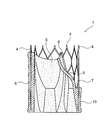
- the valved stent 1 is placed in the blood vessel 2 by being placed inside the enormous portion 3 of the blood vessel 2 in which the blood vessel wall bulges radially outward, such as the aortic sinus of the aorta.
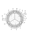
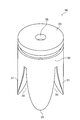
- a tubular stent body 4 For providing a valve function, a tubular stent body 4, a leaflet 5 made of a connective tissue body projecting radially inward from the stent body 4 and capable of opening and closing the blood vessel 2 in the blood flow direction, and a stent A contact portion 6 made of a connective tissue that covers the main body 4 and contacts the blood vessel wall.
- the stent body 4 is, for example, a mesh-like metal member having a shape in which thin metal wires are arranged in an oblique lattice shape, and the exposed portion 7 between the plurality of contact portions 6 communicates with the inside and outside in the radial direction. 3 is set to a length that can be held on both sides across the blood flow direction.
- the metal constituting the stent body 4 is preferably a biocompatible metal, and examples thereof include stainless steel, titanium, tantalum, aluminum, tungsten, nickel / titanium alloy, cobalt chrome alloy, titanium / aluminum / vanadium alloy, and the like. Furthermore, biodegradable magnesium alloys and hydrolyzable polymers such as polylactic acid can also be employed.
- the stent body 4 can be placed in the enormous portion 3 without blocking the branching blood vessel 8 such as the coronary artery branching from the aortic sinus by communicating with the inside and outside of the exposed portion 7. And the area covering the blood vessel wall of the blood vessel 2 is made as small as possible. Further, since the stent body 4 straddles the enormous portion 3 in the blood flow direction, there is a gap 9 between the blood vessel wall of the enormous portion 3 and the stent 1 with valve, and when the valve is closed, the blood is once exposed to the exposed portion 7. It flows into the gap 9 from a wide range and then flows into the branch blood vessel 8. Thereby, while the blood inside the stent 1 with a valve can be smoothly flowed into the branch blood vessel 8, exact position alignment to the branch blood vessel 8 of the exposed part 7 can be made unnecessary.
- branching blood vessel 8 such as the coronary artery branching from the aortic sinus
- a plurality of leaflets 5 are juxtaposed in the circumferential direction of the stent body 4 and reciprocate radially outward and inward, for example, having three leaflets 5 to open and close the aorta in the blood flow direction. Functions as an aortic valve.
- the plurality of leaflets 5 are integrated at the proximal end portion to form an annular leaflet proximal end portion 10, and the leaflet proximal end portion 10 is formed to cover the vicinity of one end of the stent body 4. Further, both side portions of each leaflet 5 are fixed to the stent body 4 via the connection portion 6, and each of the plurality of leaflets 5 is integrated with the stent body 4 at the base end portion and the both side portions.
- a two-dot chain line is an imaginary line indicating a state in which the leaflets 5 are closed.
- the contact portion 6 is formed continuously in the blood flow direction from the leaflet proximal end portion 10 near one end of the stent body 4 to the vicinity of the other end of the stent body 4.
- the plurality of contact portions 6 are spaced apart from each other in the circumferential direction of the stent body 4, and the positions in the circumferential direction of the stent body 4 are formed so as to match the boundaries between the plurality of leaflets 5. Both sides of the leaf 5 are continuous. Between the contact portions 6, an exposed portion 7 that exposes the stent body 4 and communicates the inside and the outside is used.
- valved stent forming substrate 11 for forming the valved stent 1 as described above will be described.
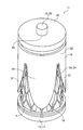
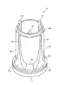
- the base body 12 includes a cylindrical portion 18 having a plurality of recesses 13 formed on the peripheral surface and a disk-shaped flange 17 having a larger diameter than the cylindrical portion 18, and the flange 17 is provided at one end of the cylindrical portion 18. As a whole, it is formed in a columnar shape. A small-diameter portion 18 a and a plurality of protrusions 19 are formed at the tip of the cylindrical portion 18, and the inner cover 15 is attached by engaging the small-diameter portion 18 a and the protrusions 19 with the flange 20 of the inner cover 15.
- the flange 17 is formed with an air hole 21 for escaping air from the inside or the inside of the cylindrical portion 18 when the inner cover 15 is attached and detached.
- the material of the base body 12 has strength (hardness) that does not greatly deform when implanted in a living body, has chemical stability, is resistant to loads such as sterilization, and stimulates the living body. Resins that have no or little eluate are preferred, and examples include, but are not limited to, silicone resins and acrylic resins.
- bulb is determined by the outer diameter of the cylinder part 18, the diameter can be changed with the target thickness.
- the concave portion 13 is set to a depth at which the cylindrical surface including the bottom surface is slightly larger in diameter than the small-diameter portion 18a, and at a plurality of locations with the substantially triangular boundary portion 22 of the cylindrical portion 18 sandwiched in the circumferential direction. It is formed over the entire length excluding the small diameter portion 18a.
- a taper 23 is formed in the vicinity of the flange 17 in the recess 13 to facilitate entry of connective tissue into the leaflet formation space 14 when the leaflet 5 is formed.
- the inner cover 15 is made of, for example, acrylic resin, and includes a plurality of substantially semi-elliptical cover pieces 24, a flange 20 having a diameter substantially the same as the cylindrical portion 18 of the base body 12, and a peripheral portion of the flange 20. A cover piece 24 protrudes on one side.
- the cover piece 24 covers a portion excluding the peripheral portion of the recess 13 of the base body 12 to form the leaflet forming space 14, and the connective tissue body to the leaflet forming space 14 near the taper 23. Form an entrance.
- the distal end surface of the leaflet forming space 14 is constituted by one surface and a peripheral portion of the flange 20, and a groove 25 that forms the distal end shape of the leaflet 5 is formed on the one surface and the peripheral portion of the flange 20.
- an open portion 26 that exposes the boundary portion 22 of the base body 12 is formed, and the outer surfaces of the boundary portion 22 and the cover piece 24 are set to be included in a common cylindrical surface.
- a fitting recess 27 into which the small diameter portion 18a of the cylindrical portion 18 of the base body 12 is fitted and a fitting hole 28 into which the projection 19 is fitted are formed.
- the small diameter portion 18 a and the fitting concave portion 27 constitute a radial positioning portion that positions the inner cover 15 in the radial direction with respect to the base body 12.
- the protrusion 19 and the fitting hole 28 constitute a circumferential positioning portion that positions the inner cover 15 in the circumferential direction with respect to the base body 12.
- the outer cover 16 is made of, for example, acrylic resin, and has a plurality of substantially semi-elliptical cover pieces 31 and a cylindrical portion that is substantially the same diameter as the flange 17 of the base body 12 and covers the outer peripheral side of the flange 20 of the inner cover 15. 32 and a flange 33 having substantially the same diameter as the flange 17 of the base body 12.
- the cylinder part 32 protrudes in the one surface side from the peripheral part of the flange 33, and the cover piece 31 protrudes from the end of the cylinder part 32 further.
- the cover piece 31 has substantially the same shape as the cover piece 24 of the inner cover 15 and covers the outer surface of the cover piece 24 with the stent 4 interposed therebetween.
- the cover piece 31 prevents the connective tissue from entering the cover piece 24 of the inner cover 15 and forms an exposed portion 7 at a portion of the stent 4 sandwiched between the cover pieces 24 and 31. To do.
- a fitting hole 35 for fitting the fitting shaft 29 of the inner cover 15 is formed at the center of the flange 33, and a fitting hole 36 for fitting the protrusion 30 of the inner cover 15 is fitted around the fitting hole 35. Is formed.
- the fitting shaft 29 and the fitting hole 35 constitute a radial positioning portion that positions the outer cover 16 in the radial direction with respect to the inner cover 15.
- the protrusion 30 and the fitting hole 36 constitute a circumferential positioning portion that positions the outer cover 16 in the circumferential direction with respect to the inner cover 15.
- the base cover 12 is covered with the inner cover 15 in the central axis direction, and the small diameter portion 18a and the protrusion 19 at the tip of the base body 12 are fitted into the fitting recess 27 and the fitting hole 28 of the inner cover 15, respectively. Then, the inner cover 15 is attached to the substrate body 12 (FIGS. 14A and 14B). Accordingly, the inner cover 15 is positioned in the radial direction and the circumferential direction with respect to the base body 12, the recess 13 of the base body 12 is covered with the cover piece 24 of the inner cover 15, and the leaflet forming space 14 is configured. Is done.
- the stent-forming base material 11 with a valve When implanting the stent-forming base material 11 with a valve into an animal, it is performed with a minimum of incision under sufficient anesthesia, and the wound is sutured after implantation.
- part of the base material 11 for valve-formed stent formation the intraperitoneal cavity which has the volume which receives the base material 11 for valve-formed stent formation, or subcutaneous, such as an extremity part, a smart part or a back part, an abdomen, is preferable.
- the implantation is performed by a minimally invasive method and the spirit of animal welfare is respected, and is performed with a minimum of incision under sufficient anesthesia.
- a membrane-like tissue body 37 is formed around the valve-formed stent-forming base material 11 (FIG. 15B).
- the tissue body 37 is composed of an extracellular matrix such as fibroblasts and collagen.
- the extraction process of taking out the valve-formed stent-forming base material 11 from the environment where the biological tissue material exists is performed.
- the valve-formed stent-forming base material 11 taken out from the environment in which the biological tissue material exists is entirely covered with a membrane made of biological tissue.
- the tissue body 37 does not enter between the cover pieces 24 and 31 of the inner cover 15 and the outer cover 16, and the exposed portion 7 is located at a portion of the stent body 4 sandwiched between the cover pieces 24 and 31. Is formed.
- valved stent 1 can be placed in the aortic sinus and function as an aortic valve, but can also be placed in the pulmonary artery and function as a pulmonary valve.
- the opening 49 exposes the stent body 4 interposed between the base body 40 and the base cover 41 and exposes the intrusion groove 45 of the base body 40 through the stent body 4.
- the connective tissue formed around the base material 39 for forming a valved stent passes through the stent body 4 from the open portion 49 and constitutes the intrusion groove while constituting the leaflets 5 on the outer surface side of the cover piece 46. 45, and is integrated with the stent body 4 inside and outside thereof to constitute the contact portion 6.
- the shape of the intrusion groove 45 may be formed in a substantially triangular shape, and the stent body 4 and the contact part 6 may be integrated more firmly in a wide range.
- the stent main body 4 in the valve-formed stent forming base material 39 in an inverted state, the stent main body 4 is returned to the original state when the back-facing valve-mounted stent 38 is inverted and the valve-equipped stent 1 is obtained. Can be returned.
- valve-equipped stent-forming base material 39 is placed in an environment where biological tissue material exists.
- a membrane-like tissue body 37 is formed around the valve-forming stent-forming base material 39 after a predetermined time has elapsed after the installation step (FIG. 19B).
- the tissue body 37 covers the outer surface of the base material cover 41 to form the leaflet 5, and covers the portion exposed from the tip of the cover piece 46 in the cylindrical portion 43 of the base body main body 40 to cover the leaflet base end portion. 10 and covers the outside of the stent body 4 exposed from the opening 49. Further, a part of the tissue body 37 passes through the stent body 4 and enters the intrusion groove 45 to form a contact portion 6 integrated with the stent body 4, and the contact portion 6 and the leaflet proximal end portion 10 The leaflet 5 is integrated with the stent main body 4 via.
- the base body 53 includes a cylindrical tube portion 55 having a plurality of intrusion grooves 54 formed on the outer peripheral surface thereof parallel to the stop shaft, and a disk-shaped base portion 56 having substantially the same diameter as the tube portion 55.
- a base portion 56 is provided at one end of the portion 55 via a circumferential groove 57 and is formed in a columnar shape as a whole.
- the intrusion groove 54 of the base body 53 is formed in a range from the circumferential groove 57 to the vicinity of the center of the cylindrical portion 55.
- the circumferential groove 57 is set wider than the circumferential groove 45 in the second embodiment, and the stent body 4 is disposed so as to be hung on the circumferential groove 57, and the connective tissue body is invaded into the circumferential groove 57 so as to be valved.
- a leaf base end portion 10 is formed.
- the force for integrating the contact 6 formed in the opening 52 with the stent body 4 is weakened, but the contact 6 is a stent. It is difficult to inhibit deformation of the main body 4 such as a reduced diameter, and insertion of the valved stent 1 into a blood vessel or the like is facilitated.
- Other configurations are the same as those of the second embodiment.
- the bulging portion 62 is formed between the slit-shaped open portions 64 of the cylindrical portion 63 of the base material cover 61, and the outer surfaces at both end portions in the circumferential direction coincide with the outer surfaces of the cylindrical portion 63, and in the circumferential direction.
- the outer surface of the central portion bulges out in a crescent-shaped cross section so that the outer surface of the cylindrical portion 63 protrudes outward in the radial direction.
- the bulging height of the bulging portion 62 from the outer surface of the cylindrical portion 63 is set to be larger toward the proximal end side in the central axis direction of the base material cover 61 so that the valve leaf 5 is formed in a shape bulging toward the distal end. It has become.
- the leaflets 5 can be formed in a shape swelled to a sufficient size, and when the leaflets 5 of the valved stent 1 are closed, the leaflets 5 Can be closed reliably by contacting them within a sufficient range. Moreover, since the thin tissue body 37 having a sufficient elastic modulus is formed on the surface of the bulging portion 62, the leaflets 5 of the valved stent 1 constituted by the tissue body 37 are stretched and damaged. And easily open and close without resisting flow.
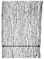
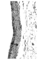
- FIG. 26 is a cross-sectional photograph of the tissue formed on the surface of the cylindrical portion where no bulging portion is provided, and it can be seen that a thick tissue having a sparse tissue is formed.
- FIG. 27 is a cross-sectional photograph of a tissue body formed on the surface of the bulge portion having a bulge height of 2 mm, and it can be seen that a thin tissue body with a dense tissue is formed.
- FIG. 28 is a cross-sectional photograph of a tissue body formed on the surface of a bulge portion having a bulge height of 3 mm. The tissue body having a dense tissue is formed thinner than the tissue body shown in FIG. I understand.
- the elastic modulus of the tissue body was measured, it was 2762 ⁇ 589 (kPa) at a bulge height of 0 mm (FIG. 26), 2055 ⁇ 329 (kPa) at a bulge height of 2 mm (FIG. 27), and the bulge height. It is 1908 ⁇ 162 (kPa) at 3 mm (FIG. 28), both greatly increasing the elastic modulus of the goat aorta 494 ⁇ 169 (kPa) and the elastic modulus of the goat leaflets 1097 ⁇ 389 (kPa). It was over.
- the tissue body formed on the surface thereof becomes thinner, and the elastic modulus of the tissue body does not extremely decrease. Compared with the elastic modulus of the leaflet, a tissue body having a sufficient elastic modulus can be obtained.
- Other configurations are the same as those of the third embodiment.
- the lateral groove 68 is set shorter than the intrusion groove 67 with substantially the same groove width and depth as the intrusion groove 67, and is an end opposite to the circumferential groove 73 in the central axis direction of the cylindrical portion 72 of the base body 66. Is formed perpendicular to the intrusion groove 67.
- the lateral opening portion 71 is set to be substantially the same width as the opening portion 70 and shorter than the opening portion 70, and is orthogonal to the opening portion 70 at a portion adjacent to the flange 75 at the base end of the cylindrical portion 74 of the base material cover 69. Is formed.
- the lateral groove 68 and the lateral opening portion 71 overlap with each other, and the connective tissue invades into the lateral groove 68 and the lateral opening portion 71.
- a T-shaped reinforcing portion is formed at the tip of the contact portion 6 formed in 70, and the contact portion 6 and the stent body 4 are more firmly integrated.
- Other configurations are the same as those in the fourth embodiment.
Landscapes
- Health & Medical Sciences (AREA)
- Engineering & Computer Science (AREA)
- Biomedical Technology (AREA)
- Cardiology (AREA)
- Life Sciences & Earth Sciences (AREA)
- Public Health (AREA)
- Heart & Thoracic Surgery (AREA)
- Vascular Medicine (AREA)
- Oral & Maxillofacial Surgery (AREA)
- Animal Behavior & Ethology (AREA)
- General Health & Medical Sciences (AREA)
- Transplantation (AREA)
- Veterinary Medicine (AREA)
- Manufacturing & Machinery (AREA)
- Gastroenterology & Hepatology (AREA)
- Pulmonology (AREA)
- Mechanical Engineering (AREA)
- Prostheses (AREA)
- Media Introduction/Drainage Providing Device (AREA)
Abstract
Description
図1~図8に示すように、弁付きステント1は、例えば、大動脈の大動脈洞など、血管壁が半径外方向に膨出する血管2の膨大部3の内部に留置して、血管2に弁機能を付与するためのものであり、筒状のステント本体4と、ステント本体4から半径内方向に突出して血管2を血流方向に開閉可能な結合組織体からなる弁葉5と、ステント本体4を覆って血管壁に接触する結合組織体からなる接触部6と、を備えている。
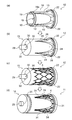
基材本体12に対して中心軸方向に内カバー15を被せ、基材本体12の先端の小径部18a及び突起19を内カバー15の嵌合凹部27及び嵌合孔28にそれぞれ嵌合させて、基材本体12に内カバー15を取り付ける(図14(a)、(b))。これにより、基材本体12に対して内カバー15が径方向及び周方向に位置決めされ、基材本体12の凹部13が内カバー15のカバー片24で覆われて、弁葉形成空間14が構成される。
弁付きステント形成用基材11を生体組織材料の存在する環境下へ置く(図15(a))。生体組織材料の存在する環境下とは、動物の生体内(例えば、皮下や腹腔内への埋入)、又は、動物の生体外において生体組織材料が浮遊する溶液中等の人工環境内が挙げられる。生体組織材料としては、ヒト、イヌ、ウシ、ブタ、ヤギ、ウサギ、ヒツジなどの他の哺乳類動物由来のものや、鳥類、魚類、その他の動物由来のもの、又は人工材料を用いることもできる。
設置工程の後、所定時間が経過することにより、弁付きステント形成用基材11の周囲に膜状の組織体37が形成される(図15(b))。組織体37は、繊維芽細胞とコラーゲンなどの細胞外マトリックスで構成される。
所定時間の形成工程を経て、組織体37が十分に形成された後、弁付きステント形成用基材11を生体組織材料の存在する環境下から取り出す取り出し工程を行う。生体組織材料の存在する環境下から取り出された弁付きステント形成用基材11は、全体を生体組織による膜に覆われている。しかし、内カバー15及び外カバー16のカバー片24、31の間には組織体37が侵入しておらず、ステント本体4のうちのカバー片24、31で挟まれた部位に露出部分7が形成されている。
弁付きステント形成用基材11の両端部及び外カバー16の表面の組織体37を除去して(図15(c))、外カバー16を取り外し(図15(d))、その後、基材本体12と内カバー15とを中心軸方向に分解して弁付きステント1の内腔より取り出し、弁付きステント1を得る(図15(e))。
本実施形態は、第1実施形態とほぼ同じであるが、一旦、弁付きステント1の内外を裏返した形状の裏向き弁付きステント38を形成し、これを裏返して弁付きステント1とするようにしている。まず、弁付きステント形成用基材39について説明する。
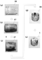
基材本体40の筒部43の外側にステント本体4を配置して、ステント本体4が基材本体40の周溝45に掛からないよう中心軸方向に位置決めし、その外側に基材本体40の先端側から基材カバー41を被せて、基材本体40の侵入溝45と基材カバー41の開放部49の位置を周方向で合わせる。これにより、開放部49からステント本体4の一部を露出させると共に、ステント本体4を介して侵入溝45を露出させつつ、基材本体40及び基材カバー41間にステント本体4を組み込んだ弁付きステント形成用基材39が組み立てられる(図19(a))。
第1実施形態と同様、弁付きステント形成用基材39を生体組織材料の存在する環境下におく。
第1実施形態と同様、設置工程の後、所定時間が経過することにより、弁付きステント形成用基材39の周囲に膜状の組織体37が形成される(図19(b))。
第1実施形態と同様、組織体37が十分に形成された後、組織体37で被覆された弁付きステント形成用基材39を生体組織材料の存在する環境下から取り出す。
弁付きステント形成用基材39の両端部の表面の組織体37を除去する(図19(c))。その際、一端側は、周溝45を露出させる分だけ組織体37を除去し、他端側は、弁葉5の先端を所定の形状に形成するよう組織体37を除去する。
取り出した裏向き弁付きステント38の内外を裏返すことにより、ステント本体4の内周側に弁葉5を有する弁付きステント1が得られる(図19(e))。その際、裏向き弁付きステント38を適度に冷やすことにより、ステント本体4の弾性を低下させて、裏向き弁付きステント38の裏返し作業を容易にすることができる。
本実施形態は、第2実施形態とほぼ同じであるが、弁付きステント形成用基材39の基材カバー41に略三角形の開放部49を形成する代わりに、図20~図22に示すように、弁付きステント形成用基材50の基材カバー51にスリット状の開放部52を形成したものである。
本実施形態は、第3実施形態とほぼ同じであるが、図23~図25に示すように、弁付きステント形成用基材60の基材カバー61に、外面側を膨出させてなる膨出部62を形成したものである。
k=P/δ …(1)
G=k(1-ν)/(4r0) …(2)
E=2G(1+ν) …(3)
E=k(1-ν2)/(2r0)=P(1-ν2)/(2δr0) …(4)
なお、上記数式中の記号は、次のものを表わす。
ν:ポアソン比(0.5として計算)
r0:プローブ半径(m)
P:荷重(g)
δ:プローブ進入量(m)
k:バネ定数
G:すれ弾性率
E:弾性率(kPa)
本実施形態は、第4実施形態とほぼ同じであるが、図29~図31に示すように、弁付きステント形成用基材65の基材本体66に侵入溝67と交差する横溝68を形成し、基材カバー69に開放部70と交差する横開放部71を形成したものである。
2 血管
3 膨大部
4 ステント本体
5 弁葉
6 接触部
7 露出部分
8 分岐血管
10 弁葉基端部
11 弁付きステント形成用基材(第1実施形態)
12 基材本体
13 凹部
14 弁葉形成空間
15 内カバー
16 外カバー
22 境界部
23 テーパー
24 カバー片
26 開放部
31 カバー片
34 開放部
37 組織体
38 裏向き弁付きステント(第2実施形態~第5実施形態)
39 弁付きステント形成用基材(第2実施形態)
40 基材本体
41 基材カバー
42 侵入溝
46 カバー片
49 開放部
50 弁付きステント形成用基材(第3実施形態)
51 基材カバー
52 開放部
53 基材本体
54 侵入溝
60 弁付きステント形成用基材(第4実施形態)
61 基材カバー
62 膨出部
64 開放部
65 弁付きステント形成用基材(第5実施形態)
66 基材本体
67 侵入溝
68 横溝
69 基材カバー
70 開放部
71 横開放部
Claims (15)
- 血管内に留置して前記血管に弁機能を付与する弁付きステントであって、筒状のステント本体と、該ステント本体から半径内方向に突出して前記血管を血流方向に開閉可能な結合組織体からなる弁葉とを備え、前記ステント本体は、半径方向で内外に連通されたことを特徴とする弁付きステント。
- 前記ステント本体は、メッシュ状の金属部材とされたことを特徴とする請求項1に記載の弁付きステント。
- 血管のうちの血管壁が半径外方向に膨出する膨大部に留置可能とされ、前記ステント本体は、前記膨大部を血流方向に跨いで両側で保持可能な長さに設定されたことを特徴とする請求項1に記載の弁付きステント。
- 前記弁葉は、その複数がステント本体の周方向に並設され、該複数の弁葉が基端部で一体化されたことを特徴とする請求項1に記載の弁付きステント。
- ステント本体を覆って血管壁に接触する接触部が結合組織体により形成され、前記接触部は、その複数がステント本体の周方向に間隔を空けて血流方向に連続して形成され、複数の前記接触部の間でステント本体が露出することを特徴とする請求項1に記載の弁付きステント。
- 前記接触部は、ステント本体の周方向における位置を複数の前記弁葉間の境界と合わせて形成されたことを特徴とする請求項5に記載の弁付きステント。
- 生体組織材料の存在する環境下におくことにより、その表面に膜状の組織体を形成して、ステント本体から半径内方向に突出する弁葉を有する弁付きステントを形成するための基材であって、
柱状の基材本体と、該基材本体の外周面に形成された複数の凹部と、該凹部を覆って前記弁葉を形成する弁葉形成空間を構成する内カバーと、該内カバーの外面側にステント本体を介在させて配置される外カバーとを備えたことを特徴とする弁付きステント形成用基材。 - 前記内カバー及び外カバーに、前記ステント本体を介して基材本体の外周面のうちの複数の前記凹部間の境界部を露出させる開放部が形成されたことを特徴とする請求項7に記載の弁付きステント形成用基材。
- 前記基材本体、内カバー及び外カバーを互いに周方向に位置決めする位置決め部が設けられたことを特徴とする請求項7に記載の弁付きステント形成用基材。
- 請求項7に記載の弁付きステント形成用基材をその内カバー及び外カバー間にステント本体を組み込んで組み立てる組立工程と、前記弁付きステント形成用基材を生体組織材料の存在する環境下におく設置工程と、前記弁付きステント形成用基材の周囲に膜状の組織体を形成する形成工程と、前記環境下から組織体で被覆された前記弁付きステント形成用基材を取り出す取り出し工程と、前記弁付きステント形成用基材から前記弁葉を含む組織体及び前記ステント本体を一体に剥離して弁付きステントとして取り出す分離工程とからなり、
前記分離工程は、弁付きステント形成用基材の両端部及び外カバーの表面の組織体を除去して、外カバーを取り外した後、前記基材本体と内カバーとを中心軸方向に分解して、弁付きステントの内腔より取り出すことを特徴とする弁付きステントの生産方法。 - 生体組織材料の存在する環境下におくことにより、その表面に膜状の組織体を形成して、ステント本体から半径内方向に突出する弁葉を有する弁付きステントの内外を裏返した形状の裏向き弁付きステントを形成するための基材であって、
柱状の基材本体と、該基材本体の外周側にステント本体を介在させて配置される基材カバーとを備えたことを特徴とする弁付きステント形成用基材。 - 前記基材カバーに、前記ステント本体を介して基材本体の外周面を露出させる開放部が形成されたことを特徴とする請求項11に記載の弁付きステント形成用基材。
- 前記基材本体の外周面に、結合組織体を侵入させる侵入溝が形成され、該侵入溝と前記開放部の位置を合わせて基材カバーが配置されることを特徴とする請求項12に記載の弁付きステント形成用基材。
- 前記基材カバーに、外面側を膨出させてなる膨出部が形成されたことを特徴とする請求項11に記載の弁付きステント形成用基材。
- 請求項11に記載の弁付きステント形成用基材をその基材本体及び基材カバー間にステント本体を組み込んで組み立てる組立工程と、前記弁付きステント形成用基材を生体組織材料の存在する環境下におく設置工程と、前記弁付きステント形成用基材の周囲に膜状の組織体を形成する形成工程と、前記環境下から組織体で被覆された前記弁付きステント形成用基材を取り出す取り出し工程と、前記弁付きステント形成用基材から前記弁葉を含む組織体及び前記ステント本体を一体に剥離して前記裏向き弁付きステントとして取り出す分離工程とを備え、
前記分離工程は、弁付きステント形成用基材の両端部の組織体を除去した後、前記基材本体と基材カバーとを中心軸方向に分解して、基材カバーを弁葉とステント本体との間から取り出すと共に、基材本体を裏向き弁付きステントの内腔より取り出す工程とされ、
前記分離工程の後に、前記裏向き弁付きステントの内外を裏返して弁付きステントとする裏返し工程が設けられたことを特徴とする弁付きステントの生産方法。
Priority Applications (5)
| Application Number | Priority Date | Filing Date | Title |
|---|---|---|---|
| JP2013503899A JP6010018B2 (ja) | 2011-09-09 | 2012-09-07 | 弁付きステント、弁付きステント形成用基材、及び弁付きステントの生産方法 |
| EP12826657.4A EP2754414A4 (en) | 2011-09-09 | 2012-09-07 | STENT WITH ONE VALVE, BASIC MATERIAL FOR FORMING THE STENT WITH ONE VALVE AND METHOD FOR PRODUCING THE STENT WITH ONE VALVE |
| CN201280002659.XA CN103220999B (zh) | 2011-09-09 | 2012-09-07 | 带瓣支架、带瓣支架形成用基材以及带瓣支架的生产方法 |
| US13/822,765 US20130178929A1 (en) | 2011-09-09 | 2012-09-07 | Valved stent, base material for forming valved stent, and method for producing valved stent |
| US14/591,379 US9956074B2 (en) | 2011-09-09 | 2015-01-07 | Valved stent, base material for forming valved stent, and method for producing valved stent |
Applications Claiming Priority (2)
| Application Number | Priority Date | Filing Date | Title |
|---|---|---|---|
| JP2011-197663 | 2011-09-09 | ||
| JP2011197663 | 2011-09-09 |
Related Child Applications (2)
| Application Number | Title | Priority Date | Filing Date |
|---|---|---|---|
| US13/822,765 A-371-Of-International US20130178929A1 (en) | 2011-09-09 | 2012-09-07 | Valved stent, base material for forming valved stent, and method for producing valved stent |
| US14/591,379 Division US9956074B2 (en) | 2011-09-09 | 2015-01-07 | Valved stent, base material for forming valved stent, and method for producing valved stent |
Publications (1)
| Publication Number | Publication Date |
|---|---|
| WO2013035864A1 true WO2013035864A1 (ja) | 2013-03-14 |
Family
ID=47832303
Family Applications (1)
| Application Number | Title | Priority Date | Filing Date |
|---|---|---|---|
| PCT/JP2012/072980 Ceased WO2013035864A1 (ja) | 2011-09-09 | 2012-09-07 | 弁付きステント、弁付きステント形成用基材、及び弁付きステントの生産方法 |
Country Status (5)
| Country | Link |
|---|---|
| US (2) | US20130178929A1 (ja) |
| EP (1) | EP2754414A4 (ja) |
| JP (1) | JP6010018B2 (ja) |
| CN (1) | CN103220999B (ja) |
| WO (1) | WO2013035864A1 (ja) |
Cited By (5)
| Publication number | Priority date | Publication date | Assignee | Title |
|---|---|---|---|---|
| JP2015047196A (ja) * | 2013-08-30 | 2015-03-16 | 独立行政法人国立循環器病研究センター | 結合組織体形成用基材、及び結合組織体の生産方法 |
| WO2016098877A1 (ja) * | 2014-12-19 | 2016-06-23 | 国立研究開発法人国立循環器病研究センター | 人工弁形成基材及び人工弁 |
| JP2017169778A (ja) * | 2016-03-23 | 2017-09-28 | 国立研究開発法人国立循環器病研究センター | 結合組織体形成基材 |
| US20210361421A1 (en) * | 2019-02-04 | 2021-11-25 | Edwards Lifesciences Corporation | Reinforced regenerative heart valves |
| JP2023135411A (ja) * | 2022-03-15 | 2023-09-28 | 国立大学法人旭川医科大学 | 弁付きグラフト形成基材 |
Families Citing this family (46)
| Publication number | Priority date | Publication date | Assignee | Title |
|---|---|---|---|---|
| US7381220B2 (en) * | 2000-09-20 | 2008-06-03 | Ample Medical, Inc. | Devices, systems, and methods for supplementing, repairing, or replacing a native heart valve leaflet |
| US8870950B2 (en) | 2009-12-08 | 2014-10-28 | Mitral Tech Ltd. | Rotation-based anchoring of an implant |
| US20110224785A1 (en) | 2010-03-10 | 2011-09-15 | Hacohen Gil | Prosthetic mitral valve with tissue anchors |
| US8579964B2 (en) | 2010-05-05 | 2013-11-12 | Neovasc Inc. | Transcatheter mitral valve prosthesis |
| US9763657B2 (en) | 2010-07-21 | 2017-09-19 | Mitraltech Ltd. | Techniques for percutaneous mitral valve replacement and sealing |
| US11653910B2 (en) | 2010-07-21 | 2023-05-23 | Cardiovalve Ltd. | Helical anchor implantation |
| US9554897B2 (en) | 2011-04-28 | 2017-01-31 | Neovasc Tiara Inc. | Methods and apparatus for engaging a valve prosthesis with tissue |
| US9308087B2 (en) | 2011-04-28 | 2016-04-12 | Neovasc Tiara Inc. | Sequentially deployed transcatheter mitral valve prosthesis |
| WO2013021374A2 (en) | 2011-08-05 | 2013-02-14 | Mitraltech Ltd. | Techniques for percutaneous mitral valve replacement and sealing |
| US8852272B2 (en) | 2011-08-05 | 2014-10-07 | Mitraltech Ltd. | Techniques for percutaneous mitral valve replacement and sealing |
| WO2013021375A2 (en) | 2011-08-05 | 2013-02-14 | Mitraltech Ltd. | Percutaneous mitral valve replacement and sealing |
| US20140324164A1 (en) * | 2011-08-05 | 2014-10-30 | Mitraltech Ltd. | Techniques for percutaneous mitral valve replacement and sealing |
| EP2609893B1 (en) * | 2011-12-29 | 2014-09-03 | Sorin Group Italia S.r.l. | A kit for implanting prosthetic vascular conduits |
| US20150351906A1 (en) | 2013-01-24 | 2015-12-10 | Mitraltech Ltd. | Ventricularly-anchored prosthetic valves |
| US9572665B2 (en) | 2013-04-04 | 2017-02-21 | Neovasc Tiara Inc. | Methods and apparatus for delivering a prosthetic valve to a beating heart |
| EP3174502B1 (en) | 2014-07-30 | 2022-04-06 | Cardiovalve Ltd | Apparatus for implantation of an articulatable prosthetic valve |
| CN107106285A (zh) * | 2014-11-13 | 2017-08-29 | 国立研究开发法人国立循环器病研究中心 | 结缔组织体形成基材及基材取出器具 |
| US9974651B2 (en) | 2015-02-05 | 2018-05-22 | Mitral Tech Ltd. | Prosthetic valve with axially-sliding frames |
| EP3253333B1 (en) | 2015-02-05 | 2024-04-03 | Cardiovalve Ltd | Prosthetic valve with axially-sliding frames |
| US10201425B2 (en) * | 2015-03-02 | 2019-02-12 | Georgia Tech Research Corporation | Implantable open vein valve |
| US10631984B2 (en) | 2015-12-15 | 2020-04-28 | Neovasc Tiara Inc. | Transseptal delivery system |
| EP4183372A1 (en) | 2016-01-29 | 2023-05-24 | Neovasc Tiara Inc. | Prosthetic valve for avoiding obstruction of outflow |
| US10531866B2 (en) | 2016-02-16 | 2020-01-14 | Cardiovalve Ltd. | Techniques for providing a replacement valve and transseptal communication |
| US10350062B2 (en) * | 2016-07-21 | 2019-07-16 | Edwards Lifesciences Corporation | Replacement heart valve prosthesis |
| US20190231525A1 (en) | 2016-08-01 | 2019-08-01 | Mitraltech Ltd. | Minimally-invasive delivery systems |
| ES3018641T3 (es) | 2016-08-10 | 2025-05-16 | Cardiovalve Ltd | Válvula protésica con marcos concéntricos |
| EP3541462A4 (en) | 2016-11-21 | 2020-06-17 | Neovasc Tiara Inc. | METHODS AND SYSTEMS FOR THE QUICK RETURN OF A TRANSCATHETER HEART VALVE RELEASE SYSTEM |
| CN108245281A (zh) * | 2016-12-28 | 2018-07-06 | 上海微创心通医疗科技有限公司 | 瓣膜假体 |
| US11246704B2 (en) | 2017-08-03 | 2022-02-15 | Cardiovalve Ltd. | Prosthetic heart valve |
| US10575948B2 (en) | 2017-08-03 | 2020-03-03 | Cardiovalve Ltd. | Prosthetic heart valve |
| US10537426B2 (en) | 2017-08-03 | 2020-01-21 | Cardiovalve Ltd. | Prosthetic heart valve |
| US12064347B2 (en) | 2017-08-03 | 2024-08-20 | Cardiovalve Ltd. | Prosthetic heart valve |
| US11793633B2 (en) | 2017-08-03 | 2023-10-24 | Cardiovalve Ltd. | Prosthetic heart valve |
| US10888421B2 (en) | 2017-09-19 | 2021-01-12 | Cardiovalve Ltd. | Prosthetic heart valve with pouch |
| CN111263622A (zh) | 2017-08-25 | 2020-06-09 | 内奥瓦斯克迪亚拉公司 | 顺序展开的经导管二尖瓣假体 |
| US12458493B2 (en) | 2017-09-19 | 2025-11-04 | Cardiovalve Ltd. | Prosthetic heart valve and delivery systems and methods |
| GB201720803D0 (en) | 2017-12-13 | 2018-01-24 | Mitraltech Ltd | Prosthetic Valve and delivery tool therefor |
| GB201800399D0 (en) | 2018-01-10 | 2018-02-21 | Mitraltech Ltd | Temperature-control during crimping of an implant |
| EP3876870B1 (en) | 2018-11-08 | 2023-12-20 | Neovasc Tiara Inc. | Ventricular deployment of a transcatheter mitral valve prosthesis |
| AU2020233892A1 (en) | 2019-03-08 | 2021-11-04 | Neovasc Tiara Inc. | Retrievable prosthesis delivery system |
| US11602429B2 (en) | 2019-04-01 | 2023-03-14 | Neovasc Tiara Inc. | Controllably deployable prosthetic valve |
| WO2020210652A1 (en) | 2019-04-10 | 2020-10-15 | Neovasc Tiara Inc. | Prosthetic valve with natural blood flow |
| US11779742B2 (en) | 2019-05-20 | 2023-10-10 | Neovasc Tiara Inc. | Introducer with hemostasis mechanism |
| US11311376B2 (en) | 2019-06-20 | 2022-04-26 | Neovase Tiara Inc. | Low profile prosthetic mitral valve |
| US12357459B2 (en) | 2020-12-03 | 2025-07-15 | Cardiovalve Ltd. | Transluminal delivery system |
| EP4633532A1 (en) * | 2022-12-13 | 2025-10-22 | Edwards Lifesciences Corporation | Coronary perfusion device |
Citations (10)
| Publication number | Priority date | Publication date | Assignee | Title |
|---|---|---|---|---|
| JP2005500101A (ja) * | 2001-07-16 | 2005-01-06 | エドワーズ ライフサイエンシーズ コーポレイション | 組織工学心臓弁 |
| JP2007037764A (ja) * | 2005-08-03 | 2007-02-15 | National Cardiovascular Center | 人工弁 |
| JP2007037763A (ja) | 2005-08-03 | 2007-02-15 | National Cardiovascular Center | 人工弁を有するステント |
| JP2007312821A (ja) | 2006-05-23 | 2007-12-06 | National Cardiovascular Center | 結合組織体形成基材およびそれを用いた結合組織体の製造方法 |
| JP2008537891A (ja) * | 2004-12-30 | 2008-10-02 | ベンター テクノロジーズ リミティド | 人工液流補綴装置 |
| JP2008237896A (ja) | 2007-02-26 | 2008-10-09 | National Cardiovascular Center | 結合組織体形成基材およびそれを用いた結合組織体の製造方法 |
| JP2009520535A (ja) * | 2005-12-22 | 2009-05-28 | サイメティス エスアー | 弁置換用ステント弁および手術用関連方法とシステム |
| WO2010037141A1 (en) * | 2008-09-29 | 2010-04-01 | Cardiaq Valve Technologies, Inc. | Heart valve |
| JP2010094476A (ja) | 2008-10-15 | 2010-04-30 | Shinkan Kogyo Kk | 結合組織体形成用基材およびそれを用いた結合組織体の製造方法 |
| JP2011025002A (ja) * | 2009-07-02 | 2011-02-10 | Japan Health Science Foundation | 弁付人工血管及び弁付人工血管用柱状芯基材並びに弁付人工血管の製造方法 |
Family Cites Families (9)
| Publication number | Priority date | Publication date | Assignee | Title |
|---|---|---|---|---|
| GB9701479D0 (en) * | 1997-01-24 | 1997-03-12 | Aortech Europ Ltd | Heart valve |
| US6666886B1 (en) * | 1999-02-16 | 2003-12-23 | Regents Of The University Of Minnesota | Tissue equivalent approach to a tissue-engineered cardiovascular valve |
| US6893460B2 (en) * | 2001-10-11 | 2005-05-17 | Percutaneous Valve Technologies Inc. | Implantable prosthetic valve |
| US7914569B2 (en) * | 2005-05-13 | 2011-03-29 | Medtronics Corevalve Llc | Heart valve prosthesis and methods of manufacture and use |
| US20070213813A1 (en) | 2005-12-22 | 2007-09-13 | Symetis Sa | Stent-valves for valve replacement and associated methods and systems for surgery |
| US7815923B2 (en) * | 2005-12-29 | 2010-10-19 | Cook Biotech Incorporated | Implantable graft material |
| JP5367700B2 (ja) * | 2007-06-04 | 2013-12-11 | セント ジュード メディカル インコーポレイテッド | 人工心臓弁 |
| WO2009156471A1 (en) * | 2008-06-26 | 2009-12-30 | Iberhospitex, S.A. | Prosthetic heart valve and method for making such a valve |
| JP2010088625A (ja) * | 2008-10-07 | 2010-04-22 | National Cardiovascular Center | 人工弁 |
-
2012
- 2012-09-07 WO PCT/JP2012/072980 patent/WO2013035864A1/ja not_active Ceased
- 2012-09-07 EP EP12826657.4A patent/EP2754414A4/en not_active Withdrawn
- 2012-09-07 CN CN201280002659.XA patent/CN103220999B/zh not_active Expired - Fee Related
- 2012-09-07 US US13/822,765 patent/US20130178929A1/en not_active Abandoned
- 2012-09-07 JP JP2013503899A patent/JP6010018B2/ja not_active Expired - Fee Related
-
2015
- 2015-01-07 US US14/591,379 patent/US9956074B2/en not_active Expired - Fee Related
Patent Citations (10)
| Publication number | Priority date | Publication date | Assignee | Title |
|---|---|---|---|---|
| JP2005500101A (ja) * | 2001-07-16 | 2005-01-06 | エドワーズ ライフサイエンシーズ コーポレイション | 組織工学心臓弁 |
| JP2008537891A (ja) * | 2004-12-30 | 2008-10-02 | ベンター テクノロジーズ リミティド | 人工液流補綴装置 |
| JP2007037764A (ja) * | 2005-08-03 | 2007-02-15 | National Cardiovascular Center | 人工弁 |
| JP2007037763A (ja) | 2005-08-03 | 2007-02-15 | National Cardiovascular Center | 人工弁を有するステント |
| JP2009520535A (ja) * | 2005-12-22 | 2009-05-28 | サイメティス エスアー | 弁置換用ステント弁および手術用関連方法とシステム |
| JP2007312821A (ja) | 2006-05-23 | 2007-12-06 | National Cardiovascular Center | 結合組織体形成基材およびそれを用いた結合組織体の製造方法 |
| JP2008237896A (ja) | 2007-02-26 | 2008-10-09 | National Cardiovascular Center | 結合組織体形成基材およびそれを用いた結合組織体の製造方法 |
| WO2010037141A1 (en) * | 2008-09-29 | 2010-04-01 | Cardiaq Valve Technologies, Inc. | Heart valve |
| JP2010094476A (ja) | 2008-10-15 | 2010-04-30 | Shinkan Kogyo Kk | 結合組織体形成用基材およびそれを用いた結合組織体の製造方法 |
| JP2011025002A (ja) * | 2009-07-02 | 2011-02-10 | Japan Health Science Foundation | 弁付人工血管及び弁付人工血管用柱状芯基材並びに弁付人工血管の製造方法 |
Non-Patent Citations (1)
| Title |
|---|
| See also references of EP2754414A4 |
Cited By (6)
| Publication number | Priority date | Publication date | Assignee | Title |
|---|---|---|---|---|
| JP2015047196A (ja) * | 2013-08-30 | 2015-03-16 | 独立行政法人国立循環器病研究センター | 結合組織体形成用基材、及び結合組織体の生産方法 |
| WO2016098877A1 (ja) * | 2014-12-19 | 2016-06-23 | 国立研究開発法人国立循環器病研究センター | 人工弁形成基材及び人工弁 |
| JP2017169778A (ja) * | 2016-03-23 | 2017-09-28 | 国立研究開発法人国立循環器病研究センター | 結合組織体形成基材 |
| US20210361421A1 (en) * | 2019-02-04 | 2021-11-25 | Edwards Lifesciences Corporation | Reinforced regenerative heart valves |
| JP2023135411A (ja) * | 2022-03-15 | 2023-09-28 | 国立大学法人旭川医科大学 | 弁付きグラフト形成基材 |
| JP7769849B2 (ja) | 2022-03-15 | 2025-11-14 | 国立大学法人旭川医科大学 | 弁付きグラフト形成基材 |
Also Published As
| Publication number | Publication date |
|---|---|
| CN103220999B (zh) | 2016-04-06 |
| EP2754414A1 (en) | 2014-07-16 |
| CN103220999A (zh) | 2013-07-24 |
| US9956074B2 (en) | 2018-05-01 |
| JPWO2013035864A1 (ja) | 2015-03-23 |
| EP2754414A4 (en) | 2015-09-02 |
| US20150119970A1 (en) | 2015-04-30 |
| JP6010018B2 (ja) | 2016-10-19 |
| US20130178929A1 (en) | 2013-07-11 |
Similar Documents
| Publication | Publication Date | Title |
|---|---|---|
| JP6010018B2 (ja) | 弁付きステント、弁付きステント形成用基材、及び弁付きステントの生産方法 | |
| EP3231392B1 (en) | Substrate for forming artificial valve and artificial valve | |
| WO2016076416A1 (ja) | 結合組織体形成基材及び基材取出具 | |
| PH26921A (en) | Tissue graft composition | |
| JP2015039515A (ja) | 人工弁、人工弁形成用基材、及び人工弁の生産方法 | |
| WO2009156471A1 (en) | Prosthetic heart valve and method for making such a valve | |
| JP2012135406A (ja) | 生体由来組織形成基材、これを用いた生体由来組織の生産方法及び生体由来組織 | |
| JP6262470B2 (ja) | 結合組織体形成用基材、及び結合組織体の生産方法 | |
| CN102958468A (zh) | 带瓣管腔状组织形成用基材、带瓣管腔状组织的生产方法及带瓣人工血管 | |
| JP5676115B2 (ja) | 弁付人工血管及び弁付人工血管用柱状芯基材並びに弁付人工血管の製造方法 | |
| JP5658008B2 (ja) | 弁付き人工血管形成用基材、これを用いた弁付き人工血管の生産方法及び弁付き人工血管 | |
| WO2014021073A1 (ja) | 人工角膜及び人工角膜の生産方法 | |
| JP2010088625A (ja) | 人工弁 | |
| JP2017169778A (ja) | 結合組織体形成基材 | |
| JP2016136984A (ja) | 管状組織体形成基材 | |
| JP2014030598A (ja) | 膜状結合組織体形成用基材及びこれを用いた膜状結合組織体の生産方法 | |
| JP2015039577A (ja) | 人工弁、人工弁形成用基材、及び人工弁の生産方法 | |
| JP7698827B2 (ja) | 結合組織体形成用構造集合体および結合組織体の形成方法 | |
| JP2017113051A (ja) | 膜状結合組織体形成用基材 | |
| JP7769849B2 (ja) | 弁付きグラフト形成基材 | |
| JP5706282B2 (ja) | 弁付き管腔形状組織形成用基材、管腔形状組織形成用基材、膜状組織形成用基材、弁付き管腔形状組織の生産方法、管腔形状組織の生産方法、及び膜状組織の生産方法 | |
| WO2014010323A1 (ja) | 膜状結合組織体形成用基材及びこれを用いた膜状結合組織体の生産方法 |
Legal Events
| Date | Code | Title | Description |
|---|---|---|---|
| WWE | Wipo information: entry into national phase |
Ref document number: 201280002659.X Country of ref document: CN |
|
| ENP | Entry into the national phase |
Ref document number: 2013503899 Country of ref document: JP Kind code of ref document: A |
|
| WWE | Wipo information: entry into national phase |
Ref document number: 2012826657 Country of ref document: EP |
|
| WWE | Wipo information: entry into national phase |
Ref document number: 13822765 Country of ref document: US |
|
| 121 | Ep: the epo has been informed by wipo that ep was designated in this application |
Ref document number: 12826657 Country of ref document: EP Kind code of ref document: A1 |
|
| NENP | Non-entry into the national phase |
Ref country code: DE |