WO2013038699A1 - 風力発電装置 - Google Patents
風力発電装置 Download PDFInfo
- Publication number
- WO2013038699A1 WO2013038699A1 PCT/JP2012/005886 JP2012005886W WO2013038699A1 WO 2013038699 A1 WO2013038699 A1 WO 2013038699A1 JP 2012005886 W JP2012005886 W JP 2012005886W WO 2013038699 A1 WO2013038699 A1 WO 2013038699A1
- Authority
- WO
- WIPO (PCT)
- Prior art keywords
- blade
- wind turbine
- electrode
- flow
- wind
- Prior art date
- Legal status (The legal status is an assumption and is not a legal conclusion. Google has not performed a legal analysis and makes no representation as to the accuracy of the status listed.)
- Ceased
Links
Images


Classifications
-
- F—MECHANICAL ENGINEERING; LIGHTING; HEATING; WEAPONS; BLASTING
- F03—MACHINES OR ENGINES FOR LIQUIDS; WIND, SPRING, OR WEIGHT MOTORS; PRODUCING MECHANICAL POWER OR A REACTIVE PROPULSIVE THRUST, NOT OTHERWISE PROVIDED FOR
- F03D—WIND MOTORS
- F03D7/00—Controlling wind motors
- F03D7/02—Controlling wind motors the wind motors having rotation axis substantially parallel to the air flow entering the rotor
-
- F—MECHANICAL ENGINEERING; LIGHTING; HEATING; WEAPONS; BLASTING
- F03—MACHINES OR ENGINES FOR LIQUIDS; WIND, SPRING, OR WEIGHT MOTORS; PRODUCING MECHANICAL POWER OR A REACTIVE PROPULSIVE THRUST, NOT OTHERWISE PROVIDED FOR
- F03D—WIND MOTORS
- F03D1/00—Wind motors with rotation axis substantially parallel to the air flow entering the rotor
- F03D1/06—Rotors
- F03D1/065—Rotors characterised by their construction elements
- F03D1/0675—Rotors characterised by their construction elements of the blades
-
- F—MECHANICAL ENGINEERING; LIGHTING; HEATING; WEAPONS; BLASTING
- F03—MACHINES OR ENGINES FOR LIQUIDS; WIND, SPRING, OR WEIGHT MOTORS; PRODUCING MECHANICAL POWER OR A REACTIVE PROPULSIVE THRUST, NOT OTHERWISE PROVIDED FOR
- F03D—WIND MOTORS
- F03D7/00—Controlling wind motors
- F03D7/02—Controlling wind motors the wind motors having rotation axis substantially parallel to the air flow entering the rotor
- F03D7/022—Adjusting aerodynamic properties of the blades
- F03D7/0232—Adjusting aerodynamic properties of the blades with flaps or slats
-
- F—MECHANICAL ENGINEERING; LIGHTING; HEATING; WEAPONS; BLASTING
- F05—INDEXING SCHEMES RELATING TO ENGINES OR PUMPS IN VARIOUS SUBCLASSES OF CLASSES F01-F04
- F05B—INDEXING SCHEME RELATING TO WIND, SPRING, WEIGHT, INERTIA OR LIKE MOTORS, TO MACHINES OR ENGINES FOR LIQUIDS COVERED BY SUBCLASSES F03B, F03D AND F03G
- F05B2240/00—Components
- F05B2240/20—Rotors
- F05B2240/30—Characteristics of rotor blades, i.e. of any element transforming dynamic fluid energy to or from rotational energy and being attached to a rotor
- F05B2240/305—Flaps, slats or spoilers
- F05B2240/3052—Flaps, slats or spoilers adjustable
-
- F—MECHANICAL ENGINEERING; LIGHTING; HEATING; WEAPONS; BLASTING
- F05—INDEXING SCHEMES RELATING TO ENGINES OR PUMPS IN VARIOUS SUBCLASSES OF CLASSES F01-F04
- F05B—INDEXING SCHEME RELATING TO WIND, SPRING, WEIGHT, INERTIA OR LIKE MOTORS, TO MACHINES OR ENGINES FOR LIQUIDS COVERED BY SUBCLASSES F03B, F03D AND F03G
- F05B2240/00—Components
- F05B2240/20—Rotors
- F05B2240/30—Characteristics of rotor blades, i.e. of any element transforming dynamic fluid energy to or from rotational energy and being attached to a rotor
- F05B2240/31—Characteristics of rotor blades, i.e. of any element transforming dynamic fluid energy to or from rotational energy and being attached to a rotor of changeable form or shape
-
- Y—GENERAL TAGGING OF NEW TECHNOLOGICAL DEVELOPMENTS; GENERAL TAGGING OF CROSS-SECTIONAL TECHNOLOGIES SPANNING OVER SEVERAL SECTIONS OF THE IPC; TECHNICAL SUBJECTS COVERED BY FORMER USPC CROSS-REFERENCE ART COLLECTIONS [XRACs] AND DIGESTS
- Y02—TECHNOLOGIES OR APPLICATIONS FOR MITIGATION OR ADAPTATION AGAINST CLIMATE CHANGE
- Y02E—REDUCTION OF GREENHOUSE GAS [GHG] EMISSIONS, RELATED TO ENERGY GENERATION, TRANSMISSION OR DISTRIBUTION
- Y02E10/00—Energy generation through renewable energy sources
- Y02E10/70—Wind energy
- Y02E10/72—Wind turbines with rotation axis in wind direction
Definitions
- Embodiments of the present invention relate to a wind power generator provided with an airflow generation device that generates an airflow by the action of discharge plasma.
- the wind speed and direction of wind are affected by natural winds, so the rotational speed of the wind turbine changes with time. Focusing on the blade cross section (blade element) at a position where the wind turbine blade is located, the blade element is affected by the combined flow of the main flow flowing toward the wind turbine blade and the relative flow generated by the rotation of the wind turbine blade itself. For this reason, when the rotational speed of the windmill changes due to the change in the speed and direction of the mainstream (wind surrounding the windmill), the inflow angle of the combined flow with respect to the windmill blade, that is, the angle of attack changes.
- the lift of a wing depends on the angle of attack, and the lift increases as the angle of attack increases. However, if the angle of attack increases beyond a certain threshold, the flow on the back side of the wing is separated, and the lift is reduced (stall state).
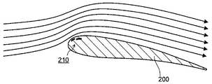
- FIG. 13 and FIG. 14 are diagrams schematically showing the flow on the blade surface of a general blade 200.
- the airflow generator 210 provided on the blade surface is not operated, and the flow is separated on the blade surface (peeling portion 220).
- the airflow generation device 210 is operated from the state of FIG. 13 to generate an airflow, and flow separation on the blade surface is suppressed.
- chord length of the wind turbine blade is about 1 to 4 m. Even in such a large windmill blade, it is required to install an airflow generation device that generates an airflow by discharge plasma on the surface of the windmill blade to reliably suppress separation of the flow on the blade surface.
- the problem to be solved by the present invention is to provide a wind power generator capable of suppressing the power consumption in the airflow generator, reliably suppressing the separation of the flow on the blade surface, and improving the efficiency.
- a wind turbine generator includes a first blade fixed to a rotation shaft, a wind turbine blade including a second blade fixed to be rotatable and adjustable in a chord length direction, the first blade, A blade surface of at least one of the second blades is provided with a pair of electrodes spaced apart via a dielectric, and a voltage application mechanism capable of applying a voltage between the pair of electrodes.
- FIG. 3 is a diagram schematically showing an AA cross section of FIG. 2 showing a wind turbine blade of the wind turbine generator according to the first embodiment. It is the perspective view which showed typically one of the windmill blades of the other structure of the wind power generator of 1st Embodiment. It is the perspective view which showed typically one of the windmill blades of the wind power generator of 2nd Embodiment.
- FIG. 6 is a diagram schematically showing a BB cross section of FIG. 5 showing a wind turbine blade of a wind turbine generator according to a second embodiment.
- FIG. 10 is a diagram schematically showing a DD cross section of FIG. 9 showing a wind turbine blade of a wind turbine generator according to a fourth embodiment. It is the perspective view which showed typically one of the windmill blades of the wind power generator of 5th Embodiment.
- FIG. 12 is a diagram schematically showing a cross section taken along line EE of FIG.
- FIG 11 showing a wind turbine blade of a wind turbine generator according to a fifth embodiment. It is the figure which showed typically the flow on the blade surface of a general wing
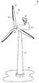
- FIG. 1 is a perspective view schematically showing the wind turbine generator 10 of the first embodiment.
- a nacelle 22 containing a generator (not shown) and the like is attached to the top of a tower 21 installed on the ground 20.
- An anemometer 23 for measuring the wind direction and speed of the wind is provided on the top surface of the nacelle 22.
- the rotor 30 is attached to the rotating shaft of the generator protruding from the nacelle 22.
- the rotor 30 includes a hub 31 and a wind turbine blade 32 attached to the hub 31.
- the wind turbine blade 32 has a divided blade structure divided in the chord length direction, and is provided with, for example, a changeable pitch angle.
- a plurality of airflow generators 40 are provided at a front edge portion of the windmill blade 32 at a predetermined interval from the blade root of the windmill blade 32 toward the blade tip.
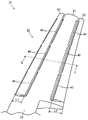
- FIG. 2 is a perspective view schematically showing one of the wind turbine blades 32 of the wind turbine generator 10 of the first embodiment.
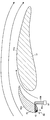
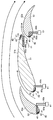
- FIG. 3 is a diagram schematically showing the AA cross section of FIG. 2 showing the wind turbine blade 32 of the wind turbine generator 10 of the first embodiment.
- FIG. 3 the flow on the surface of the wind turbine blade 32 is indicated by arrows. Although the configuration of one wind turbine blade 32 will be described here, the configuration of the other wind turbine blade 32 is the same.
- the wind turbine blade 32 has a shape in which the chord length gradually decreases from the blade root toward the blade tip.
- the wind turbine blade 32 is divided into two in the chord length direction, and includes a front divided blade 50 that is a divided blade on the front edge side, and a main blade 51. That is, the wind turbine blade 32 includes a front divided blade 50 and a main blade 51 that have a divided portion in the blade width direction from the blade root toward the blade tip and extend in the blade width direction.
- the main wing 51 is attached to the rotating shaft via the hub 31.
- blade 51 have a wing
- the main wing 51 functions as a first wing
- the front split wing 50 is fixed so as to form a gap with the main wing 51, and also has a function as a so-called slat.
- the front split blade 50 is fixed by adjusting the angle of attack and the like to an optimum angle based on, for example, the result of numerical analysis of the flow assuming that the wind power generator 10 is operating.
- segmentation blade 50 is being fixed so that an angle of attack etc. can be adjusted to an optimal angle in the environment where the wind power generator 10 is installed.
- the chord length L1 of the front split blade 50 is preferably 1 m or less even in a long portion.
- the airflow generation device 40 provided at the front edge of the front split blade 50 is separated from the first electrode 41 via the first electrode 41 and the dielectric 42.
- the second electrode 43 is provided. Note that the first electrode 41 and the second electrode 43 function as a pair of electrodes.
- the first electrode 41 is made of, for example, a plate-like conductive member.
- the shape of the first electrode 41 is not limited to a plate shape, and may be, for example, a bar shape such as a circle or rectangle in cross section.
- the second electrode 43 is composed of, for example, a plate-like conductive member, like the first electrode 41.
- the shape of the second electrode 43 is not limited to a plate shape, and may be, for example, a rod shape having a circular or rectangular cross section. Note that the second electrode 43 may have the same shape as the first electrode 41.
- the second electrode 43 is located at a position deeper than the first electrode 41 from the surface of the dielectric 42, and at a position shifted in the airflow direction from the first electrode 41.
- the first electrode 41 is spaced apart from the first electrode 41.
- dielectric material constituting the dielectric 42 examples include an electrically insulating material such as an inorganic insulator such as alumina, glass, and mica, an organic insulator such as polyimide, glass epoxy, rubber, and Teflon (registered trademark). However, it is not particularly limited.
- the dielectric material constituting the dielectric 42 can be appropriately selected from known dielectric materials made of solids according to the intended use and environment.
- the airflow generation device 40 includes a first electrode 41 provided so that one surface thereof is flush with the surface of the dielectric 42, and a second electrode 43 embedded in the dielectric 42. ing. Note that the first electrode 41 may be embedded in the dielectric 42, that is, one surface of the first electrode 41 may not be exposed to the outside.
- the edge of the first electrode 41 on the second electrode 43 side is the front split blade. It is preferable to arrange the first electrode 41 so as to be on the 50 front edges. And it is preferable to arrange
- the structure of the airflow generation device 40 is not limited to this.
- a groove is formed at the front edge of the front split blade 50, and the first electrode 41, the dielectric 42, and the first electrode 41 and the dielectric 42 are spaced apart from each other in the groove.
- the front split blade 50 is made of a dielectric material such as GFRP (glass fiber reinforced resin) obtained by solidifying glass fiber with a synthetic resin
- the front split blade 50 itself is used as the dielectric 42. May function. That is, the first electrode 41 may be disposed directly on the surface of the front split blade 50, and the second electrode 43 may be directly embedded in the front split blade 50 at a distance from the first electrode 41.
- a plurality of airflow generators 40 are independently arranged in the blade width direction from the blade root of the front split blade 50 toward the blade tip, for example.
- each airflow generation device 40 may be controlled independently, or the same control may be performed on the plurality of airflow generation devices 40.
- one airflow generation device 40 can be arranged in the blade width direction on the front edge of the front split blade 50.
- the first electrode 41 and the second electrode 43 are electrically connected to a discharge power supply 61 that functions as a voltage application mechanism via cable wirings 60a and 60b, respectively.
- a discharge power supply 61 that functions as a voltage application mechanism via cable wirings 60a and 60b, respectively.
- the discharge power supply 61 is provided in the nacelle 22, for example.
- the discharge power supply 61 applies a voltage to the airflow generation device 40 via, for example, cable wirings 60 a and 60 b wired inside the wind turbine blade 32 and the hub 31.
- the rotating part and the stationary part are electrically connected by, for example, a brush or a discharge gap.
- the discharge power supply 61 outputs, for example, a voltage having a pulse shape (positive polarity, negative polarity, positive / negative polarity (alternating voltage)) or alternating current (sine wave, intermittent sine wave).
- the discharge power supply 61 can apply a voltage between the first electrode 41 and the second electrode 43 by changing current voltage characteristics such as a voltage value, a frequency, a current waveform, and a duty ratio.
- the lift of the entire wind turbine blade 32 is improved by the flow from the gap between the front split blade 50 and the main blade 51 toward the back side 51 a of the main blade 51.
- the airflow generation device 40 when a voltage is applied between the first electrode 41 and the second electrode 43 and a potential difference equal to or greater than a certain threshold value is reached, the first electrode 41 and the second electrode 43 Discharge is induced between the two electrodes 43. This discharge is called barrier discharge, and low temperature plasma is generated.
- the gas can be ionized to generate electrons and ions without almost heating the gas.
- the generated electrons and ions are driven by an electric field and collide with gas molecules.
- the momentum of electrons and ions shifts to gas molecules. That is, by applying a discharge, an air flow is generated along the surface of the dielectric 42 from the vicinity of the electrode.
- the magnitude and direction of the airflow can be controlled by changing the current-voltage characteristics such as the voltage, frequency, current waveform, and duty ratio applied between the electrodes.
- the air flow generation device 40 is provided at the front edge portion of the front split blade 50 to generate an air flow, whereby the front split blade 50 Flow separation on the blade upper surface can be suppressed. Thereby, the efficiency can be improved.
- the power consumption of the airflow generator 40 that functions to suppress the separation of the flow along the front split blade 50 by making the wind turbine blade 32 a split blade structure including the front split blade 50 and the main blade 51. Can be suppressed. Furthermore, the lift of the entire wind turbine blade 32 is improved by the flow from the gap between the front split blade 50 and the main blade 51 toward the back side of the main blade 51.
- FIG. 4 is a perspective view schematically showing one of the wind turbine blades 32 of another configuration of the wind turbine generator 10 of the first embodiment.
- a plurality of airflow generators 40 may be provided at predetermined intervals in a direction along the rear edge from the front edge of the front split blade 50.
- two airflow generation devices 40 are provided in a direction along the rear edge from the front edge of the front divided blade 50. Note that, even at other positions, a plurality of airflow generation devices 40 may be provided in a direction along the rear edge from the front edge of the front split blade 50.
- wing can be applied also in other embodiment shown below, and obtains the same effect. be able to.
- FIG. 5 is a perspective view schematically showing one of the wind turbine blades 32 of the wind turbine generator 11 according to the second embodiment.
- FIG. 6 is a diagram schematically showing a BB cross section of FIG. 5 showing the wind turbine blade 32 of the wind turbine generator 11 of the second embodiment.
- the flow on the surface of the wind turbine blade 32 is indicated by arrows.
- symbol is attached
- the wind turbine blade 32 of the wind turbine generator 11 is divided into two in the chord length direction, and includes a mother blade 51 and a rear divided blade 52 that is a divided blade on the trailing edge side.
- the wind turbine blade 32 includes a main blade 51 and a rear divided blade 52 that have a divided portion in the blade width direction from the blade root toward the blade tip and extend in the blade width direction.
- the main wing 51 is attached to the rotating shaft via the hub 31. Further, the main wing 51 and the rear split wing 52 have a wing shape as shown in FIG.
- the rear split wing 52 functions as a second wing.
- the rear split wing 52 is fixed so as to form a gap with the main wing 51, and also has a function as a so-called flap.
- the rear split blade 52 is fixed by adjusting the angle of attack and the like to an optimum angle based on, for example, the results of numerical analysis of the flow when the wind power generator 11 is in operation.
- the rear split blade 52 is fixed so that the angle of attack and the like can be adjusted to an optimum angle in an environment where the wind power generator 10 is installed.
- the chord length L2 of the rear split blade 52 is preferably 1 m or less even in a long portion for the same reason as that of the range of the chord length L1 of the front split blade 50 in the first embodiment.
- a plurality of airflow generators 40 are provided on the front edge of the rear split blade 52 at predetermined intervals in the direction from the blade root of the wind turbine blade 32 to the blade tip.
- the configuration and installation method of the airflow generation device 40 are the same as those in the first embodiment.
- the airflow generation device 40 at the front edge of the rear divided blade 52 and generating the airflow, separation of the flow on the upper surface of the rear divided blade 52 can be suppressed. Thereby, the efficiency can be improved.
- the windmill blade 32 a split blade structure including the main blade 51 and the rear split blade 52, the power consumption of the airflow generator 40 that functions to suppress separation of the flow along the rear split blade 52 is suppressed. Can do.
- the lift of the entire wind turbine blade 32 is improved by the flow from the gap between the main wing 51 and the rear divided blade 52 toward the back side 52 a of the rear divided blade 52.
- a plurality of airflow generators 40 may be provided at the front edge of the main wing 51 in the direction from the blade root of the wind turbine blade 32 to the blade tip. Thereby, the flow separation on the blade upper surface of the main wing 51 can be suppressed.
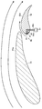
- FIG. 7 is a perspective view schematically showing one of the wind turbine blades 32 of the wind turbine generator 12 according to the third embodiment.
- FIG. 8 is a diagram schematically showing a CC cross section of FIG. 7 in which the wind turbine blade 32 of the wind turbine generator 12 of the third embodiment is shown. In FIG. 8, the flow on the surface of the wind turbine blade 32 is indicated by arrows.
- the wind turbine blade 32 of the wind turbine generator 12 is divided into three in the chord length direction, a front divided blade 50 that is a divided blade on the leading edge side, and a main blade 51. And a rear divided blade 52 which is a divided blade on the trailing edge side. That is, the wind turbine blade 32 includes a front divided blade 50, a main blade 51, and a rear divided blade 52 that have a divided portion in the blade width direction from the blade root to the blade tip and extend in the blade width direction.
- the main wing 51 is attached to the rotating shaft via the hub 31. Further, the front split wing 50, the main wing 51 and the rear split wing 52 have a wing shape as shown in FIG.
- front split blade 50 is configured as described in the first embodiment
- rear split blade 52 is configured as described in the second embodiment.
- a plurality of airflow generators 40 are provided at the front edges of the front split blade 50 and the rear split blade 52 at predetermined intervals in the direction from the blade root to the blade tip of the wind turbine blade 32. Is provided.
- the configuration and installation method of the airflow generation device 40 are the same as those in the first embodiment.
- the air flow generation device 40 is provided at the front edge portion of the front split blade 50 and the rear split blade 52 to generate an air flow, thereby separating the flow on the blade upper surfaces of the front split blade 50 and the rear split blade 52. Can be suppressed. Thereby, the efficiency can be improved.
- the wind turbine blade 32 has a split blade structure including the front split blade 50, the main blade 51, and the rear split blade 52, thereby suppressing flow separation along the front split blade 50 and the rear split blade 52.
- the power consumption of the airflow generation device 40 that is allowed to function can be suppressed.
- the lift toward the entire wind turbine blade 32 is improved by the flow toward the back side 52a.
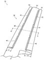
- FIG. 9 is a perspective view schematically showing one of the wind turbine blades 32 of the wind turbine generator 13 of the fourth embodiment.
- FIG. 10 is a diagram schematically showing a DD cross section of FIG. 9 in which the wind turbine blade 32 of the wind turbine generator 13 of the fourth embodiment is shown. In FIG. 10, the flow on the surface of the wind turbine blade 32 is indicated by arrows.
- the wind turbine blade 32 of the wind turbine generator 13 is divided into three in the chord length direction, a front divided blade 50 that is a divided blade on the leading edge side, and a main blade 51. And a rear divided blade 52 which is a divided blade on the trailing edge side.
- the configurations of the front split blade 50, the main blade 51, and the rear split blade 52 are the same as those of the third embodiment.
- a plurality of airflow generators 40 are provided at the rear edges of the front split blade 50 and the main blade 51 at predetermined intervals in the direction from the root of the wind turbine blade 32 to the blade tip. Is provided.
- the configuration of the airflow generation device 40 is the same as the configuration in the first embodiment. *
- the airflow generation device 40 includes a first electrode 41 provided so that one surface thereof is flush with the blade surfaces of the front split blade 50 and the main blade 51, And a second electrode 43 embedded in the dielectric 42.
- the first electrode 41 may be embedded in the dielectric 42, that is, one surface of the first electrode 41 may not be exposed to the outside.
- the first electrode 41 and the second electrode 43 function as a pair of electrodes.
- the airflow generation device 40 composed of the first electrode 41, the dielectric 42 and the second electrode 43 is thin and does not affect the flow even if installed on the blade surface, the airflow You may install the generator 40 on a blade surface.
- the air flow generated from the air flow generation device 40 installed in this manner flows on the blade surfaces of the front split blade 50 and the back sides 50a and 51a of the main blade 51 toward the rear edge.
- the air flow generation device 40 at the rear edge portions of the front split blade 50 and the main blade 51 and generating the air flow, the flow at the rear edge portion where the separation flow tends to occur is drawn toward the blade surface side. Therefore, generation
- the wind turbine blade 32 into a split blade structure including the front split blade 50, the main blade 51, and the rear split blade 52, as shown in FIG. 10, a gap between the front split blade 50 and the main blade 51 is obtained. From the gap between the main wing 51 and the rear split wing 52, a flow toward the back side 52a of the rear split wing 52 occurs. By these flows, the lift of the entire wind turbine blade 32 is improved.
- FIG. 11 is a perspective view schematically showing one of the wind turbine blades 32 of the wind turbine generator 14 of the fifth embodiment.
- FIG. 12 is a diagram schematically showing the EE cross section of FIG. 11 in which the wind turbine blade 32 of the wind turbine generator 14 of the fifth embodiment is shown. In FIG. 12, the flow on the surface of the wind turbine blade 32 is indicated by arrows.
- the wind turbine blade 32 of the wind turbine generator 14 is divided into three in the chord length direction, a front divided blade 50 that is a divided blade on the leading edge side, and a main blade 51. And a rear divided blade 52 which is a divided blade on the trailing edge side.
- the configurations of the front split blade 50, the main blade 51, and the rear split blade 52 are the same as those of the third embodiment.
- the front edge portions of the front split blade 50, the main blade 51, and the rear split blade 52 are arranged at a predetermined interval in the direction from the blade root to the blade tip of the wind turbine blade 32.
- An airflow generation device 40 is provided. Further, as shown in FIG. 11, a plurality of airflow generation devices 40 are provided at the rear edge of the main wing 51 at a predetermined interval from the blade root of the wind turbine blade 32 to the blade tip. .
- the structure of the airflow generation device 40 is the same as the structure in the first embodiment.
- the installation method of the airflow generation device 40 is the same as the installation method of the first embodiment when the airflow generation device 40 is provided at the front edge, and the airflow generation device 40 is provided at the rear edge. This is the same as the installation method of the fourth embodiment.
- the front split blade 50, the main blade 51, and the rear split blade are provided by providing the air flow generation device 40 at the front edges of the front split blade 50, the main blade 51, and the rear split blade 52, and generating an air flow. Flow separation on the upper surface of the blade 52 can be suppressed. Thereby, the efficiency can be improved.
- the wind turbine blade 32 by separating the wind turbine blade 32 from the split blade structure including the front split blade 50, the main blade 51, and the rear split blade 52, the flow separation along the front split blade 50, the main blade 51, and the rear split blade 52 is performed. It is possible to suppress the power consumption of the airflow generation device 40 that functions to suppress the airflow.
- the airflow generation device 40 at the rear edge of the main wing 51 and generating the airflow, the flow at the rear edge where the separation flow is likely to occur is drawn toward the blade surface. Therefore, generation
- the wind turbine blade 32 into a split blade structure including the front split blade 50, the main blade 51, and the rear split blade 52, as shown in FIG. 12, a gap between the front split blade 50 and the main blade 51 is obtained. From the gap between the main wing 51 and the rear split wing 52, a flow toward the back side 52a of the rear split wing 52 occurs. By these flows, the lift of the entire wind turbine blade 32 is improved.
- the air flow generation device 40 is provided at the front edge portion and the rear edge portion of the divided wind turbine blade 32 is shown.
- the air flow is generated on the other blade surface portion where the flow separation occurs.
- a generator 40 may be provided.
Landscapes
- Engineering & Computer Science (AREA)
- Life Sciences & Earth Sciences (AREA)
- Sustainable Development (AREA)
- Sustainable Energy (AREA)
- Chemical & Material Sciences (AREA)
- Combustion & Propulsion (AREA)
- Mechanical Engineering (AREA)
- General Engineering & Computer Science (AREA)
- Physics & Mathematics (AREA)
- Fluid Mechanics (AREA)
- Wind Motors (AREA)
Abstract
気流発生装置における消費電力を抑え、翼面上における流れの剥離を確実に抑制し、効率向上を図ることができる風力発電装置を提供する。実施形態の風力発電装置10は、回転軸に固定された母翼51、および回動調整可能に固定された前部分割翼50を翼弦長方向に備えた風車翼32と、母翼51および前部分割翼50の少なくとも一方の翼の翼面に、誘電体42を介して離間して配置された、第1の電極41および第2の電極43と、第1の電極41と第2の電極43との間に電圧を印加可能な放電用電源61とを備える。
Description
本発明の実施形態は、放電プラズマの作用により気流を発生させる気流発生装置を備えた風力発電装置に関する。
現在、地球温暖化防止の観点から、全地球規模で再生エネルギ発電システムの導入が進められている。そのような状況の中、風力発電は、普及が進められている発電方式の一つである。
しかしながら、風力発電は、風速変動や風向変動によって発電量が左右される。そのため、日本などのように風速および風向がめまぐるしく変わる山岳性気象を有する地域においては、発電出力を安定維持することが困難である。このようなことが、風力発電システムの導入の妨げとなっている。そのため、安定かつ高効率な風力発電システムの開発が要求されている。
実機風車においては、風速や風向の変動が激しい自然風の影響を受けるため、風車の回転数は、時間とともに変化する。風車翼のある位置における翼断面(翼素)に注目すると、翼素は、風車翼に向かって流れる主流と風車翼自身の回転によって生じる相対流との合成流れの影響を受ける。そのため、主流(風車を取り巻く風)の速度や向きが変化することで風車の回転速度が変わると、風車翼に対する合成流れの流入角、すなわち迎角が変化する。
一般に、翼の揚力は、迎角に依存し、迎角が大きくなるにつれて揚力は増加する。しかしながら、ある閾値以上に迎角が増大すると、翼の背側の流れが剥離して、揚力が低下する(失速状態)。
実機風車では、風速や風向の変動に応じて頻繁に迎角が変わり、迎角が閾値を越えると、流れの剥離が頻繁に生じる。これによって、風車トルクが減少し、発電効率が低下する。これまでの実機風車においては、風の短時間の変動に、ピッチ制御やヨー制御が対応できなかった。そのため、発電が不安定になり、高効率の風力発電システムを実現することができなかった。
そこで、放電プラズマによって気流を発生させる気流発生装置を風車翼面に設置して、翼面上を流れる風の流れを制御する技術が検討されている。ここで、図13および図14は、一般的な翼200の翼面上の流れを模式的に示した図である。図13では、翼面に設けられた気流発生装置210を作動させていない状態であり、翼面において流れが剥離している(剥離部220)。一方、図14では、図13の状態から気流発生装置210を作動させて気流を発生させ、翼面における流れの剥離が抑制されている。
このように、翼面上に気流を発生させることで、翼周りの剥離流れが抑制され、風速や風向が変動した場合においても安定して風車トルクを得られる可能性が見出されている。
実機風車においては、風車翼の翼弦長は、1~4m程度である。このような大型風車翼においても、放電プラズマによって気流を発生させる気流発生装置を風車翼面に設置して、翼面上における流れの剥離を確実に抑制することが要求されている。
大型風車翼の翼面上における流れの剥離を確実に抑制するためには、例えば、流量および流速が大きな気流を発生させる必要がある。気流発生装置において、流量および流速が大きな気流を発生させるためには、投入電力の大幅な増大が必要となる。
そのため、気流発生装置における電力の消費が増大し、風力発電システムとしての効率が低減するという問題があった。
本発明が解決しようとする課題は、気流発生装置における消費電力を抑え、翼面上における流れの剥離を確実に抑制し、効率向上を図ることができる風力発電装置を提供することである。
実施形態の風力発電装置は、回転軸に固定された第1の翼、および回動調整可能に固定された第2の翼を翼弦長方向に備えた風車翼と、前記第1の翼および前記第2の翼の少なくとも一方の翼の翼面に、誘電体を介して離間して配置された一対の電極と、前記一対の電極間に電圧を印加可能な電圧印加機構とを備える。
以下、本発明の実施の形態について図面を参照して説明する。
(第1の実施の形態)
図1は、第1の実施の形態の風力発電装置10を模式的に示した斜視図である。図1に示すように、風力発電装置10において、地面20に設置されたタワー21の頂部に発電機(図示しない)などを収容したナセル22が取付けられている。ナセル22の上面には、風の風向や速度を計測する風向風速計23が設けられている。
図1は、第1の実施の形態の風力発電装置10を模式的に示した斜視図である。図1に示すように、風力発電装置10において、地面20に設置されたタワー21の頂部に発電機(図示しない)などを収容したナセル22が取付けられている。ナセル22の上面には、風の風向や速度を計測する風向風速計23が設けられている。
また、ナセル22から突出した発電機の回転軸にロータ30が取り付けられている。このロータ30は、ハブ31、およびこのハブ31に取り付けられた風車翼32を備えている。風車翼32は、翼弦長方向に分割された分割翼構造を有し、例えば、ピッチ角が変更可能に備えられている。なお、ここでは、3枚の風車翼32を備える一例を示しているが、風車翼の数は、限定されるものではない。風車翼32の前縁部には、風車翼32の翼根から翼端の方向に、所定の間隔をあけて、複数の気流発生装置40が設けられている。
次に、風車翼32の構造について説明する。
図2は、第1の実施の形態の風力発電装置10の風車翼32の一つを模式的に示した斜視図である。図3は、第1の実施の形態の風力発電装置10の風車翼32が示された図2のA-A断面を模式的に示す図である。
なお、図3には、風車翼32の表面における流れを矢印で示している。また、ここでは、一つの風車翼32の構成について説明するが、他の風車翼32の構成も同じである。
図2に示すように、風車翼32は、翼根から翼端に向かって翼弦長が徐々に短くなる形状を有している。また、風車翼32は、翼弦長方向に2分割され、前縁側の分割翼である前部分割翼50と、母翼51とを備える。すなわち、風車翼32は、翼根から翼端に向かう翼幅方向に分割部を有して、翼幅方向に延びる、前部分割翼50および母翼51を備える。母翼51は、ハブ31を介して回転軸に取り付けられている。また、前部分割翼50および母翼51は、図3に示すように、翼形状を有している。なお、母翼51は、第1の翼として機能し、前部分割翼50は、第2の翼として機能する。
前部分割翼50は、母翼51との間に隙間を形成するように固定され、いわゆるスラットとしての機能も兼ね備えている。ここで、前部分割翼50は、例えば、風力発電装置10の作動時を想定した流れの数値解析の結果などに基づいて、迎角などが最適な角度に調整されて固定されている。なお、前部分割翼50は、風力発電装置10が設置される環境下において、迎角などを最適な角度に調整可能なように固定されている。
前部分割翼50の翼弦長L1は、長い部分でも1m以下とすることが好ましい。翼弦長L1をこの範囲とすることで、前部分割翼50に沿う流れのレイノルズ数Re(翼弦長基準)を105のオーダにすることができる。気流発生装置40から気流を発生することにより風車翼32の翼面における剥離流れを抑制して揚力を向上することができる。この効果は、レイノルズ数Reが106オーダになると急激に低下することが発明者らの研究から明らかになった。一方、レイノルズ数Reを105オーダにすることで、風車翼32の揚力を1割から3割またはそれ以上に増大することができる。さらに、翼弦長L1をこの範囲とすることで、前部分割翼50に沿う流れの剥離を抑制するために、気流発生装置40によって気流を発生させる際の消費電力を抑えることができる。
ここで、図3に示すように、前部分割翼50の前縁部に設けられた気流発生装置40は、第1の電極41と、この第1の電極41と誘電体42を介して離間して配設された第2の電極43とを備える。なお、第1の電極41および第2の電極43は、一対の電極として機能する。
第1の電極41は、例えば、板状の導電部材で構成される。第1の電極41の形状は、板状に限らず、例えば、断面が円、矩形などの棒状などであってもよい。
第2の電極43は、第1の電極41と同様に、例えば、板状の導電部材で構成される。第2の電極43の形状は、板状の限らず、例えば、断面が円、矩形などの棒状などであってもよい。なお、第2の電極43は、第1の電極41と同じ形状であってもよい。
また、第2の電極43は、図3に示すように、第1の電極41よりも誘電体42の表面から深い位置で、かつ第1の電極41よりも気流の流れる方向にずらした位置に、第1の電極41と離間して配置されている。このように気流発生装置40を配置することで、気流発生装置40によって発生された気流が第1の電極41側から第2の電極43側に向かって流れる。
誘電体42を構成する誘電材料として、例えば、電気的絶縁材料である、アルミナやガラス、マイカなどの無機絶縁物、ポリイミド、ガラスエポキシ、ゴム、テフロン(登録商標)等の有機絶縁物などが挙げられるが、特に限定されるものではない。誘電体42を構成する誘電材料は、使用される用途や環境に応じて、公知な固体からなる誘電材料から適宜選択することができる。
ここでは、気流発生装置40は、一方の表面が誘電体42の表面と同一面となるように設けられた第1の電極41と、誘電体42内に埋設された第2の電極43を備えている。なお、第1の電極41を誘電体42内に埋設させた構成、すなわち、第1の電極41の一方の表面が外部に露出されない構成としてもよい。
また、前部分割翼50の前縁部に気流発生装置40を設ける場合、図3に示すように、例えば、第1の電極41の第2の電極43側の端縁が、前部分割翼50の前縁上となるように第1の電極41を配置することが好ましい。そして、第1の電極41よりも前部分割翼50の背側50aとなる位置に、第2の電極43を配置することが好ましい。この場合、気流は、前部分割翼50の前縁から翼面の背側50aに向かって流れる。
なお、気流発生装置40の構成は、これに限られるものではない。例えば、前部分割翼50の前縁部に溝部を構成し、この溝部に、第1の電極41と、誘電体42と、第1の電極41と誘電体42を介して離間して配設された第2の電極43からなる気流発生装置40を嵌め込むように設置してもよい。この際、流れを乱さないように、気流発生装置40を、前縁部の表面から突出しないように配置することが好ましい。この場合において、前部分割翼50が、例えば、グラスファイバを合成樹脂により固形化したGFRP(グラスファイバ強化樹脂)などの誘電材料で構成されているときには、誘電体42として前部分割翼50自体を機能させてもよい。すなわち、前部分割翼50の表面に直接第1の電極41を配設し、この第1の電極41と離間して前部分割翼50に第2の電極43を直接埋設してもよい。
気流発生装置40は、図2に示すように、例えば、前部分割翼50の翼根から翼端に向かう翼幅方向に、複数個独立して配置されている。この場合、各気流発生装置40は、それぞれ単独で制御されてもよいし、複数の気流発生装置40に対して同じ制御を行ってもよい。なお、翼幅が小さい場合には、例えば、1つの気流発生装置40を、前部分割翼50の前縁部に翼幅方向に配置することもできる。
第1の電極41および第2の電極43は、図3に示すように、それぞれケーブル配線60a、60bを介して、電圧印加機構として機能する放電用電源61に電気的に接続されている。この放電用電源61を起動することで、第1の電極41と第2の電極43との間に電圧が印加される。
放電用電源61は、例えば、ナセル22内に設けられる。放電用電源61は、例えば、風車翼32の内部、ハブ31を介して配線されたケーブル配線60a、60bを介して、気流発生装置40への電圧の印加を行う。なお、回転部と静止部は、例えば、ブラシや放電ギャップによって電気的に接続される。
放電用電源61は、例えば、パルス状(正極性、負極性、正負の両極性(交番電圧))や交流状(正弦波、断続正弦波)の波形を有する電圧を出力する。放電用電源61は、電圧値、周波数、電流波形、デューティ比などの電流電圧特性などを変化させて、第1の電極41と第2の電極43との間に電圧を印加することができる。
次に、風車翼32の翼面上の流れについて説明する。
風車翼32の周りに流れが付着しているとき、翼上面の流速と翼下面の流速の差から風車翼32には揚力が発生する。風車翼32の迎角を大きくすると揚力は増大するが、ある迎角以上では、例えば、前部分割翼50の翼上面から流れが剥離して揚力が低下する。
その際、放電用電源61から第1の電極41と第2の電極43との間に電圧を印加し、翼上面に沿って気流を発生させることで、翼境界層における流速分布が変化するため、流れの剥離の発生が抑えられる。また、その他の空力現象に起因する騒音や振動などを低減することができる。
また、図3に示すように、前部分割翼50と母翼51との隙間から母翼51の背側51aに向かう流れによって、風車翼32全体の揚力が向上される。
なお、気流発生装置40においては、上記したように、第1の電極41と第2の電極43との間に電圧が印加され、一定の閾値以上の電位差となると、第1の電極41と第2の電極43との間に放電が誘起される。この放電は、バリア放電とよばれ、低温プラズマが生成される。
この放電においては、気体中の電子のみにエネルギを与えることができるため、気体をほとんど加熱せずに気体を電離して電子およびイオンを生成することができる。生成された電子やイオンは、電界によって駆動され、気体分子と衝突する。これによって、電子やイオンの運動量が気体分子に移行する。すなわち、放電を印加することで、電極付近から誘電体42の表面に沿う気流が発生する。この気流の大きさや向きは、電極間に印加する電圧、周波数、電流波形、デューティ比などの電流電圧特性を変化させることで制御可能である。
上記したように、第1の実施の形態の風力発電装置10によれば、前部分割翼50の前縁部に気流発生装置40を設け、気流を発生させることで、前部分割翼50の翼上面における流れの剥離を抑制することができる。これによって、効率を向上させることができる。
また、風車翼32を前部分割翼50および母翼51を備える分割翼構造とすることで、前部分割翼50に沿う流れの剥離を抑制するために機能させる気流発生装置40の消費電力を抑えることができる。さらに、前部分割翼50と母翼51との隙間から母翼51の背側に向かう流れによって、風車翼32全体の揚力が向上される。
このように、第1の実施の形態の風力発電装置10によれば、高効率で安定した風力発電を行うことができる。
ここで、第1の実施の形態の風力発電装置10は、上記した構成に限られるものではない。図4は、第1の実施の形態の風力発電装置10の他の構成の風車翼32の一つを模式的に示した斜視図である。
図4に示すように、前部分割翼50の前縁から後縁に沿う方向に、所定の間隔をあけて複数の気流発生装置40を設けてもよい。ここでは、最も翼根側に設けられた気流発生装置40において、前部分割翼50の前縁から後縁に沿う方向に2つの気流発生装置40を設けている。なお、他の位置においても、前部分割翼50の前縁から後縁に沿う方向に、複数の気流発生装置40を設けてもよい。
このように、前部分割翼50の前縁から後縁に沿う方向に複数の気流発生装置40を備えることで、流量および流速が大きな気流を発生させることができる。また、このような構成を備えることで、例えば、翼弦長が長くなる翼根側において、より確実に流れの剥離などを抑制することができる。
なお、分割された分割翼の前縁から後縁に沿う方向に複数の気流発生装置40を備える構成は、以下に示す他の実施の形態においても適用することができ、同様の作用効果を得ることができる。
(第2の実施の形態)
図5は、第2の実施の形態の風力発電装置11の風車翼32の一つを模式的に示した斜視図である。図6は、第2の実施の形態の風力発電装置11の風車翼32が示された図5のB-B断面を模式的に示す図である。なお、図6には、風車翼32の表面における流れを矢印で示している。また、第1の実施の形態の風力発電装置10と同じ構成部分には同一の符号を付して、重複する説明を省略または簡略する(以下の実施の形態において、同様である)。
図5は、第2の実施の形態の風力発電装置11の風車翼32の一つを模式的に示した斜視図である。図6は、第2の実施の形態の風力発電装置11の風車翼32が示された図5のB-B断面を模式的に示す図である。なお、図6には、風車翼32の表面における流れを矢印で示している。また、第1の実施の形態の風力発電装置10と同じ構成部分には同一の符号を付して、重複する説明を省略または簡略する(以下の実施の形態において、同様である)。
第2の実施の形態の風力発電装置11の風車翼32は、図5に示すように、翼弦長方向に2分割され、母翼51と、後縁側の分割翼である後部分割翼52とを備える。すなわち、風車翼32は、翼根から翼端に向かう翼幅方向に分割部を有して、翼幅方向に延びる、母翼51および後部分割翼52を備える。母翼51は、ハブ31を介して回転軸に取り付けられている。また、母翼51および後部分割翼52は、図6に示すように、翼形状を有している。なお、後部分割翼52は、第2の翼として機能する。
後部分割翼52は、母翼51との間に隙間を形成するように固定され、いわゆるフラップとしての機能も兼ね備えている。ここで、後部分割翼52は、例えば、風力発電装置11の作動時を想定した流れの数値解析の結果などに基づいて、迎角などが最適な角度に調整されて固定されている。なお、後部分割翼52は、風力発電装置10が設置される環境下において、迎角などを最適な角度に調整可能なように固定されている。
後部分割翼52の翼弦長L2は、第1の実施の形態における前部分割翼50の翼弦長L1の範囲とする理由と同じ理由から、長い部分でも1m以下とすることが好ましい。
後部分割翼52の前縁部には、図5に示すように、風車翼32の翼根から翼端の方向に、所定の間隔をあけて、複数の気流発生装置40が設けられている。気流発生装置40の構成および設置方法などは、第1の実施の形態におけるそれらと同じである。
このように、後部分割翼52の前縁部に気流発生装置40を設け、気流を発生させることで、後部分割翼52の翼上面における流れの剥離を抑制することができる。これによって、効率を向上させることができる。
また、風車翼32を母翼51および後部分割翼52を備える分割翼構造とすることで、後部分割翼52に沿う流れの剥離を抑制するために機能させる気流発生装置40の消費電力を抑えることができる。
さらに、図6に示すように、母翼51と後部分割翼52との隙間から後部分割翼52の背側52aに向かう流れによって、風車翼32全体の揚力が向上される。
このように、第2の実施の形態の風力発電装置11によれば、高効率で安定した風力発電を行うことができる。
なお、母翼51の前縁部に、風車翼32の翼根から翼端の方向に複数の気流発生装置40を設けてもよい。これにより、母翼51の翼上面における流れの剥離を抑制することができる。
(第3の実施の形態)
図7は、第3の実施の形態の風力発電装置12の風車翼32の一つを模式的に示した斜視図である。図8は、第3の実施の形態の風力発電装置12の風車翼32が示された図7のC-C断面を模式的に示す図である。なお、図8には、風車翼32の表面における流れを矢印で示している。
図7は、第3の実施の形態の風力発電装置12の風車翼32の一つを模式的に示した斜視図である。図8は、第3の実施の形態の風力発電装置12の風車翼32が示された図7のC-C断面を模式的に示す図である。なお、図8には、風車翼32の表面における流れを矢印で示している。
第3の実施の形態の風力発電装置12の風車翼32は、図7に示すように、翼弦長方向に3分割され、前縁側の分割翼である前部分割翼50と、母翼51と、後縁側の分割翼である後部分割翼52とを備える。すなわち、風車翼32は、翼根から翼端に向かう翼幅方向に分割部を有して、翼幅方向に延びる、前部分割翼50、母翼51および後部分割翼52を備える。母翼51は、ハブ31を介して回転軸に取り付けられている。また、前部分割翼50、母翼51および後部分割翼52は、図8に示すように、翼形状を有している。
ここで、前部分割翼50は、第1の実施の形態で説明したとおりの構成であり、後部分割翼52は、第2の実施の形態で説明したとおりの構成である。
前部分割翼50および後部分割翼52の前縁部には、図7に示すように、風車翼32の翼根から翼端の方向に、所定の間隔をあけて、複数の気流発生装置40が設けられている。気流発生装置40の構成および設置方法などは、第1の実施の形態におけるそれらと同じである。
このように、前部分割翼50および後部分割翼52の前縁部に気流発生装置40を設け、気流を発生させることで、前部分割翼50および後部分割翼52の翼上面における流れの剥離を抑制することができる。これによって、効率を向上させることができる。
また、風車翼32を、前部分割翼50、母翼51および後部分割翼52を備える分割翼構造とすることで、前部分割翼50および後部分割翼52に沿う流れの剥離を抑制するために機能させる気流発生装置40の消費電力を抑えることができる。
さらに、図8に示すように、前部分割翼50と母翼51との隙間から母翼51の背側51aに向かう流れ、および母翼51と後部分割翼52との隙間から後部分割翼52の背側52aに向かう流れによって、風車翼32全体の揚力が向上される。
このように、第3の実施の形態の風力発電装置12によれば、高効率で安定した風力発電を行うことができる。
(第4の実施の形態)
図9は、第4の実施の形態の風力発電装置13の風車翼32の一つを模式的に示した斜視図である。図10は、第4の実施の形態の風力発電装置13の風車翼32が示された図9のD-D断面を模式的に示す図である。なお、図10には、風車翼32の表面における流れを矢印で示している。
図9は、第4の実施の形態の風力発電装置13の風車翼32の一つを模式的に示した斜視図である。図10は、第4の実施の形態の風力発電装置13の風車翼32が示された図9のD-D断面を模式的に示す図である。なお、図10には、風車翼32の表面における流れを矢印で示している。
第4の実施の形態の風力発電装置13の風車翼32は、図9に示すように、翼弦長方向に3分割され、前縁側の分割翼である前部分割翼50と、母翼51と、後縁側の分割翼である後部分割翼52とを備える。なお、前部分割翼50、母翼51および後部分割翼52の構成は、第3の実施の形態のそれらと同じである。
前部分割翼50および母翼51の後縁部には、図9に示すように、風車翼32の翼根から翼端の方向に、所定の間隔をあけて、複数の気流発生装置40が設けられている。気流発生装置40の構成は、第1の実施の形態における構成と同じである。
ここでは、図10に示すように、気流発生装置40は、一方の表面が、前部分割翼50や母翼51の翼面と同一面となるように設けられた第1の電極41と、誘電体42内に埋設された第2の電極43とを備えている。なお、第1の電極41を誘電体42内に埋設させた構成、すなわち、第1の電極41の一方の表面が外部に露出されない構成としてもよい。なお、第1の電極41および第2の電極43は、一対の電極として機能する。
また、第1の電極41、誘電体42および第2の電極43から構成される気流発生装置40の厚さが薄く、翼面上に設置しても流れに影響を与えない場合には、気流発生装置40を翼面上に設置してもよい。
このように設置された気流発生装置40から発生する気流は、前部分割翼50や母翼51の背側50a、51aの翼面上を後縁に向かって流れる。
このように、前部分割翼50および母翼51の後縁部に気流発生装置40を設け、気流を発生させることで、剥離流れが生じやすい後縁部の流れが翼面側に引き寄せられる。そのため、大規模な剥離流れの発生を抑制することができる。これによって、効率を向上させることができる。
また、風車翼32を、前部分割翼50、母翼51および後部分割翼52を備える分割翼構造とすることで、図10に示すように、前部分割翼50と母翼51との隙間から母翼51の背側51aに向かう流れ、および母翼51と後部分割翼52との隙間から後部分割翼52の背側52aに向かう流れが生じる。これらの流れによって、風車翼32全体の揚力が向上される。
このように、第4の実施の形態の風力発電装置13によれば、高効率で安定した風力発電を行うことができる。
(第5の実施の形態)
図11は、第5の実施の形態の風力発電装置14の風車翼32の一つを模式的に示した斜視図である。図12は、第5の実施の形態の風力発電装置14の風車翼32が示された図11のE-E断面を模式的に示す図である。なお、図12には、風車翼32の表面における流れを矢印で示している。
図11は、第5の実施の形態の風力発電装置14の風車翼32の一つを模式的に示した斜視図である。図12は、第5の実施の形態の風力発電装置14の風車翼32が示された図11のE-E断面を模式的に示す図である。なお、図12には、風車翼32の表面における流れを矢印で示している。
第5の実施の形態の風力発電装置14の風車翼32は、図11に示すように、翼弦長方向に3分割され、前縁側の分割翼である前部分割翼50と、母翼51と、後縁側の分割翼である後部分割翼52とを備える。なお、前部分割翼50、母翼51および後部分割翼52の構成は、第3の実施の形態のそれらと同じである。
前部分割翼50、母翼51および後部分割翼52の前縁部には、図11に示すように、風車翼32の翼根から翼端の方向に、所定の間隔をあけて、複数の気流発生装置40が設けられている。また、母翼51の後縁部には、図11に示すように、風車翼32の翼根から翼端の方向に、所定の間隔をあけて、複数の気流発生装置40が設けられている。
なお、気流発生装置40の構成は、第1の実施の形態における構成と同じである。また、気流発生装置40の設置方法は、前縁部に気流発生装置40を備える場合は、第1の実施の形態の設置方法と同じであり、後縁部に気流発生装置40を備える場合は、第4の実施の形態の設置方法と同じである。
このように、前部分割翼50、母翼51および後部分割翼52の前縁部に気流発生装置40を設け、気流を発生させることで、前部分割翼50、母翼51および後部分割翼52の翼上面における流れの剥離を抑制することができる。これによって、効率を向上させることができる。
また、風車翼32を、前部分割翼50、母翼51および後部分割翼52を備える分割翼構造とすることで、前部分割翼50、母翼51および後部分割翼52に沿う流れの剥離を抑制するために機能させる気流発生装置40の消費電力を抑えることができる。
さらに、母翼51の後縁部に気流発生装置40を設け、気流を発生させることで、剥離流れが生じやすい後縁部の流れが翼面側に引き寄せられる。そのため、大規模な剥離流れの発生を抑制することができる。これによって、効率を向上させることができる。
また、風車翼32を、前部分割翼50、母翼51および後部分割翼52を備える分割翼構造とすることで、図12に示すように、前部分割翼50と母翼51との隙間から母翼51の背側51aに向かう流れ、および母翼51と後部分割翼52との隙間から後部分割翼52の背側52aに向かう流れが生じる。これらの流れによって、風車翼32全体の揚力が向上される。
このように、第5の実施の形態の風力発電装置14によれば、高効率で安定した風力発電を行うことができる。
なお、上記した実施の形態では、分割された風車翼32の前縁部や後縁部に気流発生装置40を備える一例を示したが、例えば、流れの剥離が生じる他の翼面部分に気流発生装置40を備えてもよい。
以上説明した実施形態によれば、気流発生装置における消費電力を抑え、翼面上における流れの剥離を確実に抑制し、効率向上を図ることが可能となる。
本発明のいくつかの実施形態を説明したが、これらの実施形態は、例として提示したものであり、発明の範囲を限定することは意図していない。これら新規な実施形態は、その他の様々な形態で実施されることが可能であり、発明の要旨を逸脱しない範囲で、種々の省略、置き換え、変更を行うことができる。これら実施形態やその変形は、発明の範囲や要旨に含まれるとともに、特許請求の範囲に記載された発明とその均等の範囲に含まれる。
10、11、12、13、14…風力発電装置、20…地面、21…タワー、22…ナセル、23…風向風速計、30…ロータ、31…ハブ、32…風車翼、40…気流発生装置、41…第1の電極、42…誘電体、43…第2の電極、50…前部分割翼、50a、51a、52a…背側、51…母翼、52…後部分割翼、60a…ケーブル配線、61…放電用電源。
Claims (6)
- 回転軸に固定された第1の翼、および回動調整可能に固定された第2の翼を翼弦長方向に備えた風車翼と、
前記第1の翼および前記第2の翼の少なくとも一方の翼の翼面に、誘電体を介して離間して配置された一対の電極と、
前記一対の電極間に電圧を印加可能な電圧印加機構と
を具備することを特徴とする風力発電装置。 - 前記第2の翼が複数備えられていることを特徴とする請求項1記載の風力発電装置。
- 前記一対の電極が、前記第1の翼および前記第2の翼の少なくとも一方の翼の翼面の前縁部に配設されていることを特徴とする請求項1または2記載の風力発電装置。
- 前記一対の電極が、前記第1の翼および前記第2の翼の少なくとも一方の翼の翼面の後縁部に配設されていることを特徴とする請求項1乃至3のいずれか1項記載の風力発電装置。
- 前記翼面の翼根から翼端に沿う方向に、所定の間隔をあけて複数の前記一対の電極が配設されていることを特徴とする請求項3または4記載の風力発電装置。
- 前記翼面の前縁から後縁に沿う方向に、所定の間隔をあけて複数の前記一対の電極が配設されていることを特徴とする請求項3乃至5のいずれか1項記載の風力発電装置。
Priority Applications (2)
| Application Number | Priority Date | Filing Date | Title |
|---|---|---|---|
| EP12832152.8A EP2757258B1 (en) | 2011-09-15 | 2012-09-14 | Wind power generator |
| US14/208,509 US20140193256A1 (en) | 2011-09-15 | 2014-03-13 | Wind power generation apparatus |
Applications Claiming Priority (2)
| Application Number | Priority Date | Filing Date | Title |
|---|---|---|---|
| JP2011-201560 | 2011-09-15 | ||
| JP2011201560A JP5734798B2 (ja) | 2011-09-15 | 2011-09-15 | 風力発電装置 |
Related Child Applications (1)
| Application Number | Title | Priority Date | Filing Date |
|---|---|---|---|
| US14/208,509 Continuation US20140193256A1 (en) | 2011-09-15 | 2014-03-13 | Wind power generation apparatus |
Publications (1)
| Publication Number | Publication Date |
|---|---|
| WO2013038699A1 true WO2013038699A1 (ja) | 2013-03-21 |
Family
ID=47882948
Family Applications (1)
| Application Number | Title | Priority Date | Filing Date |
|---|---|---|---|
| PCT/JP2012/005886 Ceased WO2013038699A1 (ja) | 2011-09-15 | 2012-09-14 | 風力発電装置 |
Country Status (4)
| Country | Link |
|---|---|
| US (1) | US20140193256A1 (ja) |
| EP (1) | EP2757258B1 (ja) |
| JP (1) | JP5734798B2 (ja) |
| WO (1) | WO2013038699A1 (ja) |
Families Citing this family (11)
| Publication number | Priority date | Publication date | Assignee | Title |
|---|---|---|---|---|
| DK2998571T3 (en) * | 2014-09-19 | 2017-12-18 | Siemens Ag | Buoyancy actuator for a rotor blade of a wind turbine |
| JP2017008834A (ja) * | 2015-06-23 | 2017-01-12 | 株式会社東芝 | 気流発生装置用電源および風力発電装置 |
| CN106870277A (zh) * | 2015-12-10 | 2017-06-20 | 李亦博 | 高效利用低速流体的叶片及其制造方法 |
| RU2660759C1 (ru) * | 2016-06-27 | 2018-07-09 | Сергей Александрович Кобка | Способ форсирования горизонтально-осевой ветровой турбины |
| JP6639335B2 (ja) * | 2016-06-28 | 2020-02-05 | 株式会社東芝 | 風力発電システム |
| US10808554B2 (en) * | 2016-11-17 | 2020-10-20 | Raytheon Technologies Corporation | Method for making ceramic turbine engine article |
| FR3062255B1 (fr) * | 2017-01-26 | 2019-06-21 | Commissariat A L'energie Atomique Et Aux Energies Alternatives | Convertisseur electrostatique |
| EP3632533B1 (en) * | 2017-05-26 | 2024-10-30 | Asahi Rubber Inc. | Airflow generation device and its manufacturing method |
| CN108150353B (zh) * | 2017-12-25 | 2019-09-27 | 江苏金风科技有限公司 | 弦长变化装置、叶片、弦长变化控制方法和控制系统 |
| JP2025532083A (ja) * | 2022-09-23 | 2025-09-29 | エスジェーケー エナジー ソリューションズ, エルエルシー | 補助偏向器を伴うタービンブレード |
| US12123391B2 (en) | 2023-01-10 | 2024-10-22 | United Arab Emirates University | Wind turbine blade having air passage with air cleaning member |
Citations (7)
| Publication number | Priority date | Publication date | Assignee | Title |
|---|---|---|---|---|
| JPS6328793A (ja) * | 1986-07-21 | 1988-02-06 | Mitsubishi Heavy Ind Ltd | スラツトおよびフラツプ付き剛体帆装置 |
| JPH05155384A (ja) * | 1991-12-04 | 1993-06-22 | Mitsubishi Heavy Ind Ltd | 航空機の主翼失速防止装置 |
| JP2007317656A (ja) * | 2006-04-28 | 2007-12-06 | Toshiba Corp | 気流発生装置、気流発生ユニット、翼、熱交換装置、マイクロマシーン、ガス処理装置、気流発生方法および気流制御方法 |
| JP2008025434A (ja) | 2006-07-20 | 2008-02-07 | Toshiba Corp | 風車翼、風力発電システムおよび風力発電システムの制御方法 |
| JP2008290711A (ja) * | 2007-05-25 | 2008-12-04 | Boeing Co:The | キャビティ上の気流を制御する方法および流れ制御システム |
| JP2009511360A (ja) * | 2005-10-17 | 2009-03-19 | ベル ヘリコプター テクストロン インコーポレイテッド | 垂直離着陸航空機の翼、ナセルおよび/または胴体への抵抗低減のためのプラズマアクチュエータ |
| JP2011163352A (ja) * | 2011-06-03 | 2011-08-25 | Toshiba Corp | 風力発電システムの制御方法 |
Family Cites Families (15)
| Publication number | Priority date | Publication date | Assignee | Title |
|---|---|---|---|---|
| US5503525A (en) * | 1992-08-12 | 1996-04-02 | The University Of Melbourne | Pitch-regulated vertical access wind turbine |
| JP4912955B2 (ja) * | 2007-05-28 | 2012-04-11 | 株式会社東芝 | 空力騒音低減装置、流体機器、移動体および回転機器 |
| US20090097976A1 (en) * | 2007-10-15 | 2009-04-16 | General Electric Company | Active damping of wind turbine blades |
| WO2009053984A1 (en) * | 2007-10-26 | 2009-04-30 | Technion - Research & Development Foundation Ltd | Aerodynamic performance enhancements using discharge plasma actuators |
| US9200522B2 (en) * | 2007-12-14 | 2015-12-01 | University Of Florida Research Foundation, Inc. | Active film cooling for turbine blades |
| US20100290906A1 (en) * | 2007-12-28 | 2010-11-18 | Moeckel Curtis W | Plasma sensor stall control system and turbomachinery diagnostics |
| US9239039B2 (en) * | 2008-10-27 | 2016-01-19 | General Electric Company | Active circulation control of aerodynamic structures |
| US8157528B1 (en) * | 2009-04-29 | 2012-04-17 | The Boeing Company | Active directional control of airflows over rotorcraft blades using plasma actuating cascade arrays |
| GB2469854A (en) * | 2009-04-30 | 2010-11-03 | Vestas Wind Sys As | Wind turbine rotor blade |
| US8162610B1 (en) * | 2009-05-26 | 2012-04-24 | The Boeing Company | Active directional control of airflows over wind turbine blades using plasma actuating cascade arrays |
| CN102884311B (zh) * | 2010-02-16 | 2015-11-25 | 技术研究及发展基金有限公司 | 对垂直轴风力涡轮机(vawt)的流控制 |
| US8038397B2 (en) * | 2010-03-09 | 2011-10-18 | General Electric Company | System and method of deicing and prevention or delay of flow separation over wind turbine blades |
| US8500404B2 (en) * | 2010-04-30 | 2013-08-06 | Siemens Energy, Inc. | Plasma actuator controlled film cooling |
| US8011887B2 (en) * | 2010-07-21 | 2011-09-06 | General Electric Company | Rotor blade assembly |
| US20110142676A1 (en) * | 2010-11-16 | 2011-06-16 | General Electric Company | Rotor blade assembly having an auxiliary blade |
-
2011
- 2011-09-15 JP JP2011201560A patent/JP5734798B2/ja not_active Expired - Fee Related
-
2012
- 2012-09-14 EP EP12832152.8A patent/EP2757258B1/en not_active Not-in-force
- 2012-09-14 WO PCT/JP2012/005886 patent/WO2013038699A1/ja not_active Ceased
-
2014
- 2014-03-13 US US14/208,509 patent/US20140193256A1/en not_active Abandoned
Patent Citations (7)
| Publication number | Priority date | Publication date | Assignee | Title |
|---|---|---|---|---|
| JPS6328793A (ja) * | 1986-07-21 | 1988-02-06 | Mitsubishi Heavy Ind Ltd | スラツトおよびフラツプ付き剛体帆装置 |
| JPH05155384A (ja) * | 1991-12-04 | 1993-06-22 | Mitsubishi Heavy Ind Ltd | 航空機の主翼失速防止装置 |
| JP2009511360A (ja) * | 2005-10-17 | 2009-03-19 | ベル ヘリコプター テクストロン インコーポレイテッド | 垂直離着陸航空機の翼、ナセルおよび/または胴体への抵抗低減のためのプラズマアクチュエータ |
| JP2007317656A (ja) * | 2006-04-28 | 2007-12-06 | Toshiba Corp | 気流発生装置、気流発生ユニット、翼、熱交換装置、マイクロマシーン、ガス処理装置、気流発生方法および気流制御方法 |
| JP2008025434A (ja) | 2006-07-20 | 2008-02-07 | Toshiba Corp | 風車翼、風力発電システムおよび風力発電システムの制御方法 |
| JP2008290711A (ja) * | 2007-05-25 | 2008-12-04 | Boeing Co:The | キャビティ上の気流を制御する方法および流れ制御システム |
| JP2011163352A (ja) * | 2011-06-03 | 2011-08-25 | Toshiba Corp | 風力発電システムの制御方法 |
Also Published As
| Publication number | Publication date |
|---|---|
| EP2757258A1 (en) | 2014-07-23 |
| US20140193256A1 (en) | 2014-07-10 |
| JP2013060930A (ja) | 2013-04-04 |
| EP2757258B1 (en) | 2019-01-16 |
| EP2757258A4 (en) | 2015-04-22 |
| JP5734798B2 (ja) | 2015-06-17 |
Similar Documents
| Publication | Publication Date | Title |
|---|---|---|
| JP5734798B2 (ja) | 風力発電装置 | |
| JP4810342B2 (ja) | 風車翼および風力発電システム | |
| JP5323133B2 (ja) | 風力発電システムの制御方法 | |
| US9989033B2 (en) | Horizontal axis wind or water turbine with forked or multi-blade upper segments | |
| JP5837323B2 (ja) | 風力発電装置 | |
| KR101368448B1 (ko) | 풍력 발전 시스템 및 그 제어 방법 | |
| JP4912955B2 (ja) | 空力騒音低減装置、流体機器、移動体および回転機器 | |
| US20160146188A1 (en) | Wind farm, wind power generation system | |
| JP6021703B2 (ja) | 風力発電システム | |
| JP6696694B2 (ja) | 風力発電システムおよび風力発電方法 | |
| JP6639335B2 (ja) | 風力発電システム | |
| JP2017091618A (ja) | 気流発生装置、風車翼、および風車 | |
| KR101381872B1 (ko) | 공기 유동 제어를 위한 표면부착용 플라즈마 발생 필름 | |
| JP2016070085A (ja) | ウィンドファーム | |
| JP6444740B2 (ja) | 風力発電システムおよび風力発電方法 | |
| JP6415926B2 (ja) | 気流発生装置、移動体、および、風力発電システム | |
| JP2013174231A (ja) | 風力発電システムおよびその制御方法 | |
| JP6403156B2 (ja) | 気流発生装置、および、風力発電システム | |
| JP6707391B2 (ja) | 気流発生装置を備えた翼、風力発電装置、および回転翼機 | |
| JP2013519018A (ja) | ブースター翼とブースター翼付き垂直軸風力発電機用風車 | |
| JP2016075231A (ja) | 風力発電システム | |
| JP2017082743A (ja) | 風力発電システムおよび風力発電方法 | |
| JP2016003623A (ja) | 気流発生装置、および、風力発電システム | |
| JP2016194280A (ja) | 風力発電システムおよび風力発電システムの制御方法 |
Legal Events
| Date | Code | Title | Description |
|---|---|---|---|
| 121 | Ep: the epo has been informed by wipo that ep was designated in this application |
Ref document number: 12832152 Country of ref document: EP Kind code of ref document: A1 |
|
| NENP | Non-entry into the national phase |
Ref country code: DE |
|
| WWE | Wipo information: entry into national phase |
Ref document number: 2012832152 Country of ref document: EP |