WO2013038751A1 - 熱発電携帯機器および熱発電携帯機器の発電制御方法 - Google Patents
熱発電携帯機器および熱発電携帯機器の発電制御方法 Download PDFInfo
- Publication number
- WO2013038751A1 WO2013038751A1 PCT/JP2012/062526 JP2012062526W WO2013038751A1 WO 2013038751 A1 WO2013038751 A1 WO 2013038751A1 JP 2012062526 W JP2012062526 W JP 2012062526W WO 2013038751 A1 WO2013038751 A1 WO 2013038751A1
- Authority
- WO
- WIPO (PCT)
- Prior art keywords
- thermoelectric
- thermal resistance
- heat
- power generation
- transfer path
- Prior art date
- Legal status (The legal status is an assumption and is not a legal conclusion. Google has not performed a legal analysis and makes no representation as to the accuracy of the status listed.)
- Ceased
Links
Images







Classifications
-
- H—ELECTRICITY
- H10—SEMICONDUCTOR DEVICES; ELECTRIC SOLID-STATE DEVICES NOT OTHERWISE PROVIDED FOR
- H10N—ELECTRIC SOLID-STATE DEVICES NOT OTHERWISE PROVIDED FOR
- H10N10/00—Thermoelectric devices comprising a junction of dissimilar materials, i.e. devices exhibiting Seebeck or Peltier effects
- H10N10/80—Constructional details
-
- G—PHYSICS
- G04—HOROLOGY
- G04C—ELECTROMECHANICAL CLOCKS OR WATCHES
- G04C10/00—Arrangements of electric power supplies in time-pieces
-
- H—ELECTRICITY
- H10—SEMICONDUCTOR DEVICES; ELECTRIC SOLID-STATE DEVICES NOT OTHERWISE PROVIDED FOR
- H10N—ELECTRIC SOLID-STATE DEVICES NOT OTHERWISE PROVIDED FOR
- H10N10/00—Thermoelectric devices comprising a junction of dissimilar materials, i.e. devices exhibiting Seebeck or Peltier effects
- H10N10/10—Thermoelectric devices comprising a junction of dissimilar materials, i.e. devices exhibiting Seebeck or Peltier effects operating with only the Peltier or Seebeck effects
- H10N10/13—Thermoelectric devices comprising a junction of dissimilar materials, i.e. devices exhibiting Seebeck or Peltier effects operating with only the Peltier or Seebeck effects characterised by the heat-exchanging means at the junction
-
- G—PHYSICS
- G04—HOROLOGY
- G04G—ELECTRONIC TIME-PIECES
- G04G19/00—Electric power supply circuits specially adapted for use in electronic time-pieces
Definitions
- the present invention relates to a thermoelectric portable device and a power generation control method for the thermoelectric portable device.
- thermoelectric generator is installed between the back cover and the heat dissipation ring inside the main body, and the temperature difference between the temperature on the heat generation side and the temperature on the heat dissipation side where body temperature is transmitted from the human arm through the back cover.
- thermoelectric wristwatch that obtains a power generation voltage by using (see, for example, Patent Document 1).
- thermoelectric wristwatch in the thermoelectric wristwatch according to the above-described prior art, the heat generating side of the thermoelectric generator is accompanied by changing toward the thermal equilibrium state so that the temperature of the entire thermoelectric wristwatch is saturated after being worn on the human arm.
- the temperature difference between this temperature and the temperature on the heat radiating side becomes small, and the power generation voltage of the thermoelectric generator decreases, so that a desired power generation amount cannot be secured and the power generation efficiency may decrease.
- the present invention has been made in view of the above circumstances, and is capable of suppressing a decrease in power generation efficiency in a state of being mounted on a living body and capable of securing a desired power generation amount and power generation control of the thermoelectric power generation mobile device. It aims to provide a method.
- thermoelectric portable device is mounted on a living body and is capable of generating electric power by the heat of the living body (for example, implementation The temperature difference between the temperature of the heat source side position and the temperature of the heat radiation destination side position between the living body that is the heat source and the heat radiation destination of the heat radiation from the thermoelectric generation portable device
- Thermoelectric power generating member for example, the thermoelectric power generating member 20 in the embodiment
- the thermal resistance changing means capable of changing the thermal resistance of at least a part of the heat transfer path between the living body and the heat radiation destination (For example, the movable member 22, the member drive part 51, and the manual operation member 61 in the embodiment).
- the thermal resistance changing means includes at least part of the thermal resistance of the heat transfer path (for example, each thermal resistance R1, R2, R3 in the embodiment). , R5) can be switched between a state in which the first thermal resistance is set and a state in which at least a part of the thermal resistance of the heat transfer path is a second thermal resistance different from the first thermal resistance.
- the thermal resistance changing means is rotatable around a rotation axis (for example, the rotation axis 22a in the embodiment) or is slidable in a predetermined direction. In association with the rotation or the slide movement, the presence or absence of interference with the heat transfer path or the position of interference with the heat transfer path changes, so that the heat resistance of at least a part of the heat transfer path can be changed.
- a member for example, the movable member 22 in the embodiment
- the movable member is a plate-like member, and the plate-like member can intersect the heat transfer path.
- thermoelectric power generation portable device the thermoelectric power generation portable device according to claim 5 of the present invention
- the movable member that is rotatable around the rotation axis has a point-symmetric shape with respect to the axis of the rotation axis.
- thermoelectric generator portable device the thermoelectric generator portable device according to claim 6 of the present invention
- the movable member that can rotate around the rotation axis has an asymmetrical shape with respect to the axis of the rotation axis.
- thermoelectric power generation portable device includes time measuring means for measuring time (for example, the control unit 31 in the embodiment) and voltage detection means for detecting the generated voltage of the thermoelectric power generation member (for example, The voltage sensor 52 in the embodiment, the power storage means for storing the power generated by the thermoelectric generator (for example, the power storage unit 34 in the embodiment), and the power storage amount detection means for detecting the power storage amount of the power storage means (For example, the charged amount sensor 53 in the embodiment), and the thermal resistance changing means includes the time measuring operation of the time measuring means, the detection result of the voltage detecting means, A member driving unit (for example, a member driving unit 51 in the embodiment) that automatically drives the movable member according to at least any one of the detection results of the storage amount detection unit is provided.
- time measuring means for measuring time for example, the control unit 31 in the embodiment
- voltage detection means for detecting the generated voltage of the thermoelectric power generation member
- the voltage sensor 52 in the embodiment the power storage means for storing the power generated by the thermoelectric generator
- the power storage amount detection means
- the time measuring means includes a second hand indicating the second of the time (for example, the second hand 17a in the embodiment) and a minute hand indicating the minute of the time (for example, A needle driving means (for example, in the embodiment) that drives at least one of the minute hand 17b in the embodiment and the hour hand indicating the time (for example, the hour hand 17c in the embodiment).
- the member driving means for automatically driving the movable member according to at least the measuring operation of the time measuring means includes the second hand, the minute hand, and the hour hand driven by the needle driving means. And the movable member is automatically driven in conjunction with at least one of them.
- the thermal resistance changing means includes a manual operation member that can manually operate the movable member (for example, the manual operation member 61 in the embodiment). .
- the thermal resistance changing means is between the living body of the heat transfer path and the thermoelectric generator member, and the heat radiation destination of the heat transfer path and the It is possible to change at least one thermal resistance (for example, each thermal resistance R1, R2, R5 in the embodiment) between the thermal power generation member and the thermal power generation member.
- the thermal resistance changing means capable of changing a thermal resistance between the living body and the thermoelectric generation member of the heat transfer path contacts the living body.
- the thermal resistance for example, thermal resistance R5 in the embodiment
- the member for example, the back cover 14 in the embodiment
- the thermal resistance changing means capable of changing a thermal resistance between the heat radiation destination of the heat transfer path and the thermoelectric generator member is the heat transfer path.
- Thermal resistance for example, thermal resistance R2 in the embodiment
- a member for example, the holding member 15 in the embodiment
- the thermal resistance changing means capable of changing a thermal resistance between the heat radiation destination of the heat transfer path and the thermoelectric generation member is the heat transfer path.
- the heat dissipation area (for example, the heat dissipation part in the embodiment) between the housing (for example, the case 11 in the embodiment) provided between the heat dissipation destination and the thermoelectric generator and the heat dissipation destination ) (For example, thermal resistance R1 in the embodiment) can be changed.
- the power generation control method of the thermoelectric portable device according to claim 14 of the present invention is the power generation control method of the thermoelectric portable device according to claim 1, wherein the heat transfer path of the thermoelectric generator is generated during power generation by the thermoelectric generator member. At least a part of the thermal resistance is changed, and after the change, at least a part of the thermal resistance of the heat transfer path is changed toward a value before the change.
- the thermoelectric power generation member made of, for example, a Peltier element is the temperature of the living body (body temperature) as a heat source and the temperature of the heat radiation destination such as the atmosphere outside the thermoelectric power generation portable device.
- the power generation voltage corresponding to the magnitude of the temperature difference generated between the heat source side position and the heat radiation destination side position of the thermoelectric generation member due to the temperature difference is output.
- the temperature difference between the heat source side position and the heat radiation destination side position of the thermoelectric generation member locally increases in the heat transfer path with respect to a predetermined temperature difference between the heat source and the heat radiation destination.
- each of the serial regions constituting the heat transfer path (for example, a member constituting the device main body or air inside the device)
- the thermal resistance of each region equal to or smaller than the thermal resistance of the thermoelectric generator member
- thermoelectric generation member The temperature difference between the heat source side position and the heat radiation side position of the thermoelectric generation member and the power generation of the thermoelectric generation member with the change toward the thermal equilibrium state so that the temperature of the entire thermoelectric portable device is saturated
- the voltage decreases, for example, by increasing the thermal resistance of an appropriate region having a serial connection relationship with the thermoelectric generator member in the heat transfer path between the heat source and the heat radiating destination, at least in the heat transfer path. Change some thermal resistance.
- thermal equilibrium state in which the predetermined temperature difference between the heat source and the heat radiation destination is distributed over the entire heat transfer path is changed, and this predetermined temperature difference is changed in the heat transfer path.
- a thermal equilibrium state is formed which is concentrated locally in a part.
- the heat resistance of the heat transfer path is changed to a state before the change (for example, The thermal resistance of each of the series regions constituting the heat transfer path is equal to or smaller than the thermal resistance of the thermoelectric generator member).
- the thermal resistance of each of the series regions constituting the heat transfer path is equal to or smaller than the thermal resistance of the thermoelectric generator member.
- thermoelectric generator device by switching the heat resistance of at least a part of the heat transfer path between the first heat resistance and the second heat resistance, between the heat source and the heat radiation destination.
- the temperature of a desired magnitude between the heat source side position and the heat radiation destination side position of the thermoelectric generation member based on a predetermined temperature difference between the heat source and the heat radiation destination A difference can be secured.
- thermoelectric portable device the movable member having a different thermal resistance, for example, depending on the presence or absence of interference with the heat transfer path by a movable member having an appropriate thermal resistance, or depending on the position, for example.
- the thermal resistance of at least a part of the heat transfer path can be changed by changing the position of interference with the heat transfer path by the member. This makes it possible to easily change the thermal resistance of at least a part of the heat transfer path while suppressing the complexity of the device configuration by simply providing a movable member that can rotate around the rotation axis or slide in a predetermined direction. can do.
- thermoelectric portable device for example, a thermal resistance that varies depending on the presence or absence of a crossing state with respect to the heat transfer path by a plate-like member having an appropriate thermal resistance, or depending on, for example, the position.
- the thermal resistance of at least a part of the heat transfer path can be changed by changing the crossing position with respect to the heat transfer path by the plate-shaped member having the plate-shaped member.
- thermoelectric portable device according to the fifth aspect of the present invention, the rotational performance of the movable member can be improved, and there is no interference with the heat transfer path accompanying rotation or interference with the heat transfer path accompanying rotation.
- the change in position can be easily generated, and the thermal resistance of at least a part of the heat transfer path can be easily changed.
- thermoelectric portable device for example, the rotation of the movable member due to the action of gravity can be improved, and the presence or absence of interference with the heat transfer path due to the rotation or the transmission due to the rotation. Changes in the position of interference with the heat path can be easily generated, and the thermal resistance of at least a part of the heat transfer path can be easily changed.
- thermoelectric portable device for example, according to a predetermined time or time, or according to, for example, a decrease in the generated voltage, or according to, for example, a decrease in the storage amount,
- a desired power generation voltage and power generation amount can be ensured, and a decrease in power generation efficiency can be suppressed.
- thermoelectric power generation portable device according to claim 8 of the present invention, a desired generated voltage and a desired power generation voltage can be reduced while suppressing the complication of the device configuration by the interlocking operation of the needle driving means and the member driving means.
- the amount of power generation can be ensured, and a decrease in power generation efficiency can be suppressed.
- thermoelectric power generation portable device according to claim 9 of the present invention, it is possible to ensure a desired power generation voltage and power generation amount according to the operator's intention, and to suppress a decrease in power generation efficiency. .
- thermoelectric power generation portable device according to any one of claims 10 to 13 of the present invention, the heat source side position and the heat radiation destination side of the thermoelectric generation member in a state where the thermoelectric generation portable device is attached to the living body. Even if the temperature difference between the position and the position is lowered, at least after the thermal resistance between the living body and the thermoelectric generation member of the heat transfer path or between the heat radiation destination and the thermoelectric generation member is temporarily increased By reducing the temperature, the temperature difference between the heat source side position and the heat radiation side position of the thermoelectric generator can be increased again. Thereby, while being able to ensure a desired electric power generation voltage and electric power generation amount, the fall of electric power generation efficiency can be suppressed.
- thermoelectric portable device According to the power generation control method for a thermoelectric portable device according to claim 14 of the present invention, the temperature of the entire thermoelectric portable device mounted on the living body is changed toward a thermal equilibrium state so that the temperature is saturated. Accordingly, even if the temperature difference between the heat source side position of the thermoelectric generation member and the heat radiation destination side position and the power generation voltage of the thermoelectric generation member are reduced, the heat source side position and the heat radiation destination side position of the thermoelectric generation member The temperature difference between them can be increased again. Thereby, while being able to ensure a desired electric power generation voltage and electric power generation amount, the fall of electric power generation efficiency can be suppressed.
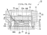
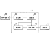
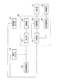
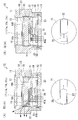
- thermoelectric power generation portable apparatus which concerns on embodiment of this invention. It is a block diagram of the movement of the thermoelectric generation portable apparatus which concerns on embodiment of this invention.
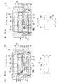
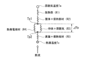
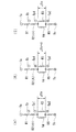
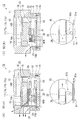
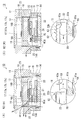
- the thermal resistance of the region including the casing and the holding member is in a state where the first thermal resistance is a small value and a state where the thermal resistance is a large value of the second thermal resistance. It is a figure which shows the state of a movable member. It is a figure which shows the thermal resistance model of the thermoelectric generation portable apparatus which concerns on embodiment of this invention.
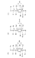
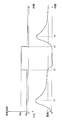
- thermoelectric power generation portable device After the thermoelectric power generation portable device according to the embodiment of the present invention is mounted on a living body, the thermal resistance of a region composed of a housing and a holding member that changes according to the state of the movable member, and the temperature distribution in the thermal resistance model FIG.
- thermoelectric portable device After the thermoelectric portable device according to the embodiment of the present invention is mounted on a living body, the thermal resistance of a region composed of a housing and a holding member that changes according to the state of the movable member, and the heat source side position of the thermoelectric generator member It is a figure which shows the change of temperature difference (DELTA) Tp which arises between the temperature of this, and the temperature of the heat radiation destination side position.
- DELTA change of temperature difference
- thermoelectric generator portable device In the thermoelectric generator portable device according to the second modification of the embodiment of the present invention, the state in which the thermal resistance of the region including the housing and the holding member becomes the first thermal resistance with a small value and the second thermal resistance with a large value It is a figure which shows the state of a movable member in the state which becomes.
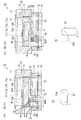
- thermoelectric portable device In the thermoelectric portable device according to the third modification of the embodiment of the present invention, the state in which the thermal resistance of the region including the housing and the holding member becomes the first thermal resistance with a small value and the second thermal resistance with a large value It is a figure which shows the state of a movable member in the state which becomes. It is a block diagram of the movement of the portable thermoelectric generator apparatus which concerns on the 3rd modification of embodiment of this invention.
- thermoelectric power generation portable device the state in which the thermal resistance of the region including the casing and the holding member becomes the first thermal resistance with a small value and the second thermal resistance with a large value It is a figure which shows the state of a movable member in the state which becomes.
- thermoelectric generator portable device the state in which the thermal resistance of the region including the housing and the holding member becomes the first thermal resistance with a small value and the second thermal resistance with a large value It is a figure which shows the state of a movable member in the state which becomes.
- thermoelectric portable device In the thermoelectric portable device according to the sixth modification of the embodiment of the present invention, the state in which the thermal resistance of the region including the housing and the holding member becomes the first thermal resistance with a small value and the second thermal resistance with a large value It is a figure which shows the state of a movable member in the state which becomes.
- thermoelectric generator portable device the state in which the thermal resistance of the region including the back cover and the heat conducting member becomes the first thermal resistance with a small value and the second thermal resistance with a large value It is a figure which shows the state of a movable member in the state which becomes.
- thermoelectric power portable device After the thermoelectric power portable device according to the eighth modification of the embodiment of the present invention is mounted on a living body, the thermal resistance of the region composed of the back cover and the heat conducting member that changes according to the state of the movable member, and the thermoelectric power generation It is a figure which shows the change of the temperature difference (DELTA) Tp which arises between the temperature of the heat source side position of a member, and the temperature of the heat radiation destination side position.
- DELTA temperature difference
- thermoelectric power generation portable device the heat resistance of the heat radiation portion formed of the surface of the thermoelectric power generation portable device and the region near the surface becomes the first heat resistance with a small value; It is a figure which shows the state of a movable member in the state used as the 2nd thermal resistance of a large value.
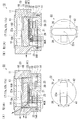
- thermoelectric power generation portable device 10 is, for example, a wrist watch that is worn on the arm of a human body, and as shown in FIG. 1, a housing 11, a frame body 12, a cover glass 13, and a back cover 14. And a holding member 15, a dial 16, a pointer portion 17, a movement 18, a substrate 19, a thermoelectric generator member 20, a heat conducting member 21, and a movable member 22.
- the casing 11 is formed in a cylindrical shape by, for example, metal, one opening end is closed by a cover glass 13, and one opening end of the cylindrical frame 12 is connected to the other opening end.
- the frame body 12 is formed in a cylindrical shape with, for example, a synthetic resin, and the other opening end is closed with a back cover 14.
- the holding member 15 is formed of a metal such as aluminum, copper, or brass, for example, and is accommodated in the housing 11 and the frame body 12.
- the dial 16 has a back surface 16B held by a movement 18 so that a front surface 16A on which indications such as seconds, minutes, and numbers of time are provided can be visually recognized through the cover glass 13. Yes.
- the pointer portion 17 includes, for example, a second hand 17a indicating the second of the time, a minute hand 17b indicating the minute of the time, and an hour hand 17c indicating the hour of the time, and is provided so as to protrude from the surface 16A of the dial 16. And an appropriate display related to the time provided on the surface 16A of the dial 16 by being rotationally driven by the movement 18.
- the movement 18 is disposed on the back surface 16 ⁇ / b> B side of the dial 16 and is held by the holding member 15.
- the movement 18 includes a control unit 31, a needle driving unit 32, a boosting unit 33, and a power storage unit 34.
- the control unit 31 includes, for example, an oscillation circuit, a frequency dividing circuit, a motor drive pulse output circuit, and the like that are operated by electric power supplied from the power storage unit 34, and according to a signal that is a reference for timing output from the frequency dividing circuit, A drive pulse for driving the needle drive unit 32 is output from the motor drive pulse output circuit.
- the needle drive unit 32 includes a stepping motor, for example, and rotationally drives the second hand 17a, the minute hand 17b, and the hour hand 17c of the pointer unit 17 in accordance with a drive pulse output from the control unit 31.
- the booster 33 includes, for example, an oscillation circuit and a charge pump circuit, and is connected to the thermoelectric generator member 20 to boost the generated voltage output from the thermoelectric generator member 20 and output the boosted voltage.
- the power storage unit 34 includes, for example, a secondary battery, a capacitor, and the like, is connected to the booster 33, and stores power output from the booster 33.
- the substrate 19 is held by, for example, the holding member 15.
- the thermoelectric generator 20 is made of, for example, a Peltier element or a thermocouple, and is held so as to be sandwiched between the holding member 15 and the heat conducting member 21.
- the heat conducting member 21 is formed in a plate shape with, for example, copper or the like and is disposed on the inner surface 14A side of the back cover 14.
- the movable member 22 is formed in an elliptical plate shape or a long plate shape with metal or the like, and has a point-symmetric shape with respect to the axis of the rotation shaft 22a. And it is accommodated in the inside of the holding member 15, and is supported so that it can rotate around the rotating shaft 22a. Thereby, the movable member 22 rotates according to the external force applied to the thermoelectric power generation portable apparatus 10 from the outside, for example.
- the movable member 22 is formed to have a thermal resistance (for example, a thermal resistance smaller than that of air) that is different from the thermal resistance of the atmosphere (such as air) inside the holding member 15 in which the movable member 22 is accommodated. ing.
- the movable member 22 is viewed from the direction from the cover glass 13 toward the back cover 14 with respect to the two thermoelectric generator members 20 and 20 arranged at point-symmetrical positions with respect to the axis of the rotation shaft 22a.
- the long side direction has a shape that can be overlapped so as to cover the two thermoelectric generators 20 and 20, and the short side direction as shown in FIG. 3 (B), for example.
- the shape that does not overlap the two thermoelectric generation members 20, 20 so as to fit between the two thermoelectric generation members 20, 20 that is, the length in the short side direction is larger than the interval between the two thermoelectric generation members 20, 20. Is also formed to have a short shape.
- the thermal resistance of the movable member 22 made of metal is the atmosphere (such as air) inside the holding member 15. Since it is smaller than the thermal resistance, the thermal resistance R ⁇ b> 2 of the region composed of the casing 11 and the holding member 15 changes according to the rotation of the movable member 22. That is, as shown in FIG. 3A, the heat transfer path of the heat flow that sequentially transmits the back cover 14, the heat conducting member 21, the thermoelectric generation member 20, the holding member 15, and the housing 11.
- the thermal resistance R2 of the region composed of the housing 11 and the holding member 15 becomes the first thermal resistance R2a having a small value, and is movable as shown in FIG.
- the thermal resistance R2 becomes the second thermal resistance R2b (> first thermal resistance R2a) having a large value.
- the back cover 14 and the heat conducting member 21 are formed between a living body that is a heat source in contact with the back cover 14 and a heat radiation destination such as an atmosphere outside the thermoelectric portable device 10.
- the thermal resistance R1, R2, R3, and R5 of the thermal power generation portable device 10 for example, the surface 11A of the housing 11
- the thermal resistance R1 of the heat dissipating part composed of a region in the vicinity of the surface
- the thermal resistance R4 is connected in series, and the thermal resistance R4 is connected in parallel to the thermal resistance R3 between the thermal resistances R2 and R5.
- thermoelectric generator 20 is caused by a temperature difference between the temperature of the living body (heat source temperature Tc) as a heat source and the temperature of the heat radiation destination (atmosphere temperature Ta) such as the atmosphere outside the thermoelectric portable device 10.
- the thermal resistances R 1 and R 5 and the thermal resistance R 2 indicating the first thermal resistance are equal to the thermal resistance R 4 of the thermoelectric generator member 20 or more than the thermal resistance R 4 of the thermoelectric generator member 20. It is comprised so that it may become small. Further, the thermal resistance R3 is configured to be larger than, for example, the thermal resistances R1, R2, R4, and R5.
- thermally conductive grease 23 is applied between the housing 11 and the holding member 15, between the holding member 15 and the thermoelectric generator member 20, between the heat conducting member 21 and the back cover 14, and the like. ing.
- thermoelectric power generation portable device 10 has the above-described configuration. Next, the operation of the thermoelectric power generation portable device 10 will be described.
- the portable thermoelectric generator is used for a living body that is a heat source having a higher temperature (heat source temperature) Tc than the temperature (atmosphere temperature) Ta of the atmosphere outside the thermoelectric generator portable device 10.
- Tc heat source temperature
- Ta atmosphere temperature
- the device 10 is mounted on a living body and the back cover 14 comes into contact with the living body, a heat flow is transmitted from the heat source to the heat source side position of the thermoelectric generator member 20 via the region composed of the back cover 14 and the heat conducting member 21.
- the temperature Tp2 at the heat source side position of the thermoelectric generation member 20 rises. For example, as shown in FIG.
- thermoelectric generation member 20 the temperature Tp2 at the heat source side position of the thermoelectric generation member 20 and the temperature Tp1 at the heat radiation destination side position
- the maximum value of the temperature difference ⁇ Tp is, for example, the thermal resistance R of the entire heat transfer path from the heat source to the heat radiating destination, the thermal resistance R4 of the thermoelectric generator member 20, and the atmosphere inside the frame 12 and the frame 12 4 (ie, a region having a parallel connection relationship with the thermoelectric generator member 20 in the thermal resistance model shown in FIG. 4), the ambient temperature Ta, and the heat source temperature Tc, the following mathematical formula (1) Is described as follows.
- thermoelectric generation member 20 As the heat flow is transmitted to the heat radiation destination side position of the thermoelectric generation member 20 and further toward the heat radiation destination through the region composed of the thermoelectric generation member 20 and the frame 12 and the atmosphere inside the frame body 12,
- the difference ⁇ Tp changes from a maximum value to a decreasing tendency, and the temperature of the entire thermoelectric portable device 10 is saturated.
- a predetermined temperature difference (Tc ⁇ Ta) between the heat source and the heat radiation destination A thermal equilibrium state is formed in which the local temperature gradient is reduced by being distributed over the entire path.
- thermoelectric portable device 10 When such a thermal equilibrium state where the temperature of the entire thermoelectric portable device 10 is saturated is maintained, a state in which the temperature difference ⁇ Tp and the generated voltage are reduced is maintained, but between the heat source and the heat radiation destination When the thermal resistance (for example, thermal resistance R2) of at least a part of the heat transfer path in FIG. 3 is changed according to the rotation of the movable member 22, a thermal transient occurs again, and the temperature difference ⁇ Tp and the generated voltage increase. .
- thermal resistance for example, thermal resistance R2
- the movable member 22 intersects the heat transfer path as shown in FIG.
- the thermal resistance R2 of the region made of is the first thermal resistance R2a having a small value, as shown in FIG. 7A, thermoelectric power generation from the heat source via the region made of the back cover 14 and the heat conducting member 21
- the heat flow is transmitted to the heat source side position of the member 20, and the temperature Tp2 at the heat source side position rises.
- the heat radiation destination side position of the thermoelectric generator member 20 is cooled by the atmosphere outside the thermoelectric generator portable device 10 via the heat radiation portion and the region composed of the housing 11 and the holding member 15, and the temperature Tp1 of the heat radiation destination side position is The rise is suppressed.
- the power generation voltage of the thermoelectric power generation member 20 increase toward the maximum value.
- thermoelectric power generation portable device 10 As the temperature of the entire thermoelectric power generation portable device 10 saturates so as to saturate, a predetermined temperature difference (Tc ⁇ Ta) between the heat source and the heat radiating destination is referred to as heat transfer.
- the local temperature gradient is reduced by being distributed over the entire path. For example, during the period from time t1 to time t2 illustrated in FIG.
- the temperature difference ⁇ Tp ( Tp2 ⁇ Tp1) generated between the temperature Tp1 of the heat radiation destination side position and the power generation voltage of the thermoelectric generator member 20 change in a decreasing tendency.
- the movable member 22 rotates around the rotation shaft 22a, and the movable member 22 does not cross the heat transfer path as shown in FIG.
- the resistance R2 changes to the second thermal resistance R2b having a large value, as shown in FIG. 7B, the region including the back cover 14 and the heat conducting member 21, the thermoelectric generator member 20 or the frame body 12, and the inside of the frame body 12
- the heat flow transmitted from the heat source to the heat radiation destination side position of the thermoelectric generator member 20 via the region composed of the atmosphere is blocked by the region composed of the casing 11 and the holding member 15.
- the temperature Tp1 at the heat radiation side position of the thermoelectric generator 20 rises to be equal to the temperature Tp2 at the heat source side position, and the temperature difference ⁇ Tp and the power generation voltage of the thermoelectric generator 20 change toward zero and change downward.
- the region composed of the housing 11 and the holding member 15 is easily cooled by the atmosphere outside the thermoelectric generator 10, and the temperature Tb of the region composed of the housing 11 and the retaining member 15 is lowered.
- the temperature distribution in the heat transfer path between the heat source and the heat radiation destination is changed by rotating the movable member 22 around the rotation shaft 22a, and the temperature Tp1 at the heat radiation destination side position of the thermoelectric generation member 20 and the housing 11 and the temperature Tb of the region composed of the holding member 15 increase.
- a thermal equilibrium state is formed in which (Tc-Ta) is locally concentrated in a part of the heat transfer path (that is, a region including the housing 11 and the holding member 15).
- the movable member 22 rotates around the rotation shaft 22a, and the movable member 22 crosses the heat transfer path again as shown in FIG.
- the thermal resistance R2 is changed to the first thermal resistance R2a having a small value, as shown in FIG. 7C
- the heat radiation destination side position of the thermoelectric generator member 20 is an area composed of the heat radiation portion, the housing 11 and the holding member 15.
- the temperature Tp ⁇ b> 1 at the heat radiation destination side position is lowered due to cooling by the atmosphere outside the thermoelectric generator portable device 10.
- the thermal transient state in which the temperature Tp1 of the heat radiation destination side position of the thermoelectric generator member 20 decreases during the period from time t3 to time t4 shown in FIG.
- thermoelectric power generation portable device 10 As described above, according to the thermoelectric power generation portable device 10 according to the present embodiment, the region including the holding member 15 and the housing 11 in which the movable member 22 is accommodated according to the rotation of the movable member 22 around the rotation shaft 22a.
- the heat resistance R2 of the thermoelectric generator 20 is locally changed with respect to a predetermined temperature difference (Tc ⁇ Ta) between the heat source and the heat radiating destination.
- the heat source Rd and the heat release destination are switched by switching the thermal resistance R2 in the region including the holding member 15 in which the movable member 22 is accommodated and the housing 11 to the first thermal resistance R2a and the second thermal resistance R2b.
- the temperature distribution in the heat transfer path between the heat source and the heat dissipating destination is changed between the heat source side position and the heat dissipating side position of the thermoelectric generator member 20 in a thermal transient state caused by the temperature distribution.
- the movable member 22 is formed in an elliptical plate shape or a long plate shape as a point-symmetric shape with respect to the axis of the rotation shaft 22a.
- the presence or absence of interference (i.e., crossing) can be easily generated, and the thermal resistance R2 of at least a part of the heat transfer path (i.e., the region including the holding member 15 and the housing 11) can be easily changed. it can.
- the movable member 22 has an elliptical plate shape or a long plate shape, and there is presence or absence of interference (that is, crossing) with respect to the heat transfer path according to the rotation of the movable member 22 around the rotation axis 22a.
- the present invention is not limited to this.
- the movable member 22 is movable as a disk having different thermal resistances depending on the position. You may form so that the position and thermal resistance of the interference (namely, crossing) with respect to a heat-transfer path
- the movable member 22 of the thermoelectric portable device 10 is composed of, for example, a first member 41 that is formed in an elliptical plate shape or a long plate shape with metal or the like and has the first thermal resistance Ra. It is configured to include a second member 42 that has a second thermal resistance Rb that is larger than the first thermal resistance Ra and is formed in a disc shape with resin or the like, and that houses the first member 41 therein. .
- the first member 41 of the movable member 22 is, for example, from the cover glass 13 to the back cover 14 with respect to the two thermoelectric generator members 20 and 20 arranged at point-symmetrical positions with respect to the axis of the rotation shaft 22a.
- 9A for example, as shown in FIG. 9A
- the long side direction has a shape that can be overlapped so as to cover the two thermoelectric generators 20 and 20, and for example, as shown in FIG. 9B.
- the shape does not overlap with the two thermoelectric generation members 20 and 20 so as to fit between the two thermoelectric generation members 20 and 20 (that is, the length of the short side direction is two thermoelectric generation members 20 and 20
- the shape is shorter than the interval between 20).
- the second member 42 of the movable member 22 is configured such that, for example, as shown in FIG. 9B, the two thermoelectric generation members 20, 20 are arranged in a state where the first member 41 does not overlap the two thermoelectric generation members 20, 20. It has a shape that overlaps so as to cover.
- the movable member 22 has a point-symmetric shape with respect to the axis of the rotation shaft 22a.
- the present invention is not limited to this, and for example, as shown in FIGS.
- the movable member 22 may be formed to have an asymmetrical shape with respect to the axis of the rotation shaft 22a.
- the movable member 22 of the thermoelectric power generation portable device 10 according to the second modification is formed in an elliptical plate shape or a long plate shape, for example, with metal or the like, and is shifted from the center, for example, one end in the long side direction.
- the rotary shaft 22a is provided at the position.
- the movable member 22 is seen from the direction which goes to the back cover 14 from the cover glass 13 with respect to the thermoelectric generation member 20 arrange
- thermoelectric generator member 20 A shape that does not overlap with the thermoelectric generator member 20 in the direction from the other end in the side direction or the long side direction to one end (that is, from the other end in the short side direction or the long side direction to the one end.
- the length from the axial center of the rotating shaft 22a in the direction of heading is formed so as to have a shape shorter than the interval from the axial center of the rotating shaft 22a to the thermoelectric generator member 20).
- the rotation of the movable member 22 due to the action of gravity is enhanced, and the presence or absence of interference (ie, crossing) with respect to the heat transfer path accompanying the rotation of the movable member 22 is easily generated. It is possible to easily change the thermal resistance R2 of at least a part of the heat transfer path (that is, the region including the holding member 15 and the housing 11).
- a member driving unit 51 that automatically drives the movable member 22 as in the thermoelectric portable device 10 according to the third modification shown in FIGS. May be provided.
- the thermoelectric power generation portable device 10 includes a voltage sensor 52 that detects a power generation voltage of the thermoelectric generator member 20, and a power storage amount sensor 53 that detects a power storage amount of the power storage unit 34.
- the member driving unit 51 is provided in the movement 18, for example, and includes a motor that rotationally drives the movable member 22.
- the member driving unit 51 includes a signal that serves as a timing reference output from the control unit 31 and a generated voltage output from the voltage sensor 52. While controlling the timing, rotational speed, and the like for rotating the movable member 22 according to at least one of the detection result signal and the storage amount detection result signal output from the storage amount sensor 53. The movable member 22 is automatically driven.
- the member driving unit 51 is based on a signal that is a reference for timing output from the control unit 31 according to a preset time, or at least of the second hand 17a, the minute hand 17b, and the hour hand 17c of the pointer unit 17.
- the movable member 22 is rotationally driven to change the thermal resistance R2 of the region composed of the holding member 15 that houses the movable member 22 and the housing 11. Thereby, the heat flow is movable as shown in FIG.
- the member driving unit 51 determines that the generated voltage is a predetermined threshold (for example, a lower limit voltage that allows the booster 33 to perform a boost operation or a thermoelectric generator based on the signal of the detection result of the generated voltage output from the voltage sensor 52. If the voltage is higher than the minimum voltage required for the operation of the mobile device 10, the movable member 22 is rotationally driven so that the heat flow passes through the movable member 22 as shown in FIG. The first thermal resistance R2a having a small value is set. Then, after the generated voltage becomes less than the predetermined threshold value, the heat flow is temporarily (for example, in a predetermined period from time t2 to time t3 shown in FIG. 8) as shown in FIG.
- a predetermined threshold for example, a lower limit voltage that allows the booster 33 to perform a boost operation or a thermoelectric generator based on the signal of the detection result of the generated voltage output from the voltage sensor 52. If the voltage is higher than the minimum voltage required for the operation of the mobile device 10, the movable member 22 is rotation
- the movable member 22 is rotationally driven so as to pass through the atmosphere (such as air) inside the holding member 15 without passing through the movable member 22, and the thermal resistance R2 is temporarily increased to the second thermal resistance R2b having a large value. Let Then, for example, after the elapse of a predetermined period, the movable member 22 is rotationally driven again so that the heat flow passes through the movable member 22 as shown in FIG. Set to thermal resistance R2a.
- the member driving unit 51 determines that the amount of charge is a predetermined threshold (for example, the lower limit power required for the operation of the thermoelectric portable device 10) based on the signal of the detection result of the amount of charge output from the charge amount sensor 53.
- a predetermined threshold for example, the lower limit power required for the operation of the thermoelectric portable device 10.
- the movable member 22 is rotationally driven so as to pass through the atmosphere (such as air) inside the holding member 15 without passing through the movable member 22, and the thermal resistance R2 is temporarily increased to the second thermal resistance R2b having a large value. Let Then, for example, after the elapse of a predetermined period, the movable member 22 is rotationally driven again so that the heat flow passes through the movable member 22 as shown in FIG. Set to thermal resistance R2a.
- thermoelectric generation member 20 for example, according to a predetermined time or time, for example, according to a decrease in the power generation voltage of the thermoelectric generation member 20, or according to, for example, a decrease in the amount of power stored in the power storage unit 34,
- a desired power generation voltage and power generation amount can be easily secured. And the fall of power generation efficiency can be controlled.
- the member driving unit 51 may be a driving mechanism that rotationally drives the movable member 22 by the power of the needle driving unit 32, for example, the power of the needle driving unit 32 with respect to the movable member 22, for example.
- a mechanism for connecting / disconnecting transmission and a transmission mechanism may be provided.
- at least the voltage sensor 52 or the storage amount sensor 53 may be omitted. In this case, the driving of the movable member 22 is controlled based on at least a signal used as a timing reference output from the control unit 31.
- the presence or absence of interference (that is, crossing) with respect to the heat transfer path is switched according to the rotation of the movable member 22 around the rotation axis 22a.
- the present invention is not limited to this.
- route may be switched.
- the movable member 22 of the thermoelectric power generation portable device 10 according to the fourth modification is formed in an elliptical plate shape or a long plate shape, for example, with metal or the like, and is housed inside the holding member 15 so as to be slidable in the long side direction.
- the movable member 22 is, for example, from the cover glass 13 to the back cover 14 with respect to the thermoelectric generation member 20 arranged at a position shifted from the center of the thermoelectric generation portable device 10 to one side in the sliding direction of the movable member 22. When viewed from the direction, for example, as shown in FIG.
- thermoelectric generation member 20 it has a shape that can be superimposed so as to cover the thermoelectric generation member 20 in a state of moving to one side in the sliding direction, and for example, shown in FIG. 13 (B).
- the shape that does not overlap with the thermoelectric generation member 20 in a state of moving to the other side in the sliding direction that is, the thermoelectric generation member 20 from the end on the other side in the sliding direction in the range in which the length in the long side direction is slidable
- the shape is shorter than the interval up to.
- the presence or absence of interference (that is, crossing) with respect to the heat transfer path associated with the sliding movement of the movable member 22 can be caused by, for example, swinging the thermoelectric portable device 10,
- the thermal resistance R2 of at least a part of the heat transfer path (that is, the region including the holding member 15 and the housing 11) can be easily changed.
- the movable member 22 is automatically driven as in the portable thermoelectric generator 10 according to the fifth modified example shown in FIGS. 14A and 14B, for example. You may provide the member drive part 51 to do.
- the thermoelectric power generation portable device 10 according to the fifth modification example is similar to the third modification example of the embodiment described above, for example, as shown in FIG. And a power storage amount sensor 53 that detects a power storage amount of the power storage unit 34.
- the member driving unit 51 is provided in the movement 18, for example, and includes a motor for sliding the movable member 22 and a gear mechanism such as a rack and pinion.
- the member driving unit 51 is a reference for timing output from the control unit 31.
- the movable member 22 according to at least one of the signal, the detection result signal of the generated voltage output from the voltage sensor 52, and the detection result signal of the storage amount output from the storage amount sensor 53.
- the movable member 22 is automatically slid while controlling the timing of moving the slide and the moving speed.
- the member driving unit 51 is based on a signal that is a reference for timing output from the control unit 31 according to a preset time, or at least of the second hand 17a, the minute hand 17b, and the hour hand 17c of the pointer unit 17.
- the movable member 22 is slid to change the thermal resistance R2 of the region composed of the holding member 15 that houses the movable member 22 and the housing 11. Thereby, the heat flow is movable as shown in FIG.
- the member driving unit 51 determines that the generated voltage is a predetermined threshold (for example, a lower limit voltage that allows the booster 33 to perform a boost operation or a thermoelectric generator based on the signal of the detection result of the generated voltage output from the voltage sensor 52.
- a predetermined threshold for example, a lower limit voltage that allows the booster 33 to perform a boost operation or a thermoelectric generator based on the signal of the detection result of the generated voltage output from the voltage sensor 52.
- the movable member 22 is slid so that the heat flow passes through the movable member 22 as shown in FIG.
- the first thermal resistance R2a having a small value is set.
- the heat flow temporarily eg, in a predetermined period from time t2 to time t3 shown in FIG. 8) as shown in FIG. 14B.
- the movable member 22 is slid so as to pass through the atmosphere (such as air) inside the holding member 15 without passing through the movable member 22, and the thermal resistance R2 is temporarily increased to the second thermal resistance R2b having a large value. Let Then, for example, after the elapse of a predetermined period, the movable member 22 is slid again so that the heat flow passes through the movable member 22 as shown in FIG. Set to thermal resistance R2a.
- the member driving unit 51 determines that the amount of charge is a predetermined threshold (for example, the lower limit power required for the operation of the thermoelectric portable device 10) based on the signal of the detection result of the amount of charge output from the charge amount sensor 53.
- a predetermined threshold for example, the lower limit power required for the operation of the thermoelectric portable device 10.
- the movable member 22 is slid so as to pass through the atmosphere (such as air) inside the holding member 15 without passing through the movable member 22, and the thermal resistance R2 is temporarily increased to the second thermal resistance R2b having a large value. Let Then, for example, after the elapse of a predetermined period, the movable member 22 is slid again so that the heat flow passes through the movable member 22 as shown in FIG. Set to thermal resistance R2a.
- the fifth modification for example, according to a predetermined time or time, for example, according to a decrease in the power generation voltage of the thermoelectric generation member 20, or according to a decrease in the amount of power stored in the power storage unit 34, for example.
- a predetermined time or time for example, according to a decrease in the power generation voltage of the thermoelectric generation member 20, or according to a decrease in the amount of power stored in the power storage unit 34, for example.
- the member driving unit 51 may be, for example, a driving mechanism that slides the movable member 22 with the power of the needle driving unit 32.
- the member driving unit 51 may change speed with a mechanism that connects and disconnects transmission of the power of the needle driving unit 32 to the movable member 22.
- a mechanism and the like may be provided.
- at least the voltage sensor 52 or the storage amount sensor 53 may be omitted. In this case, the driving of the movable member 22 is controlled based on a signal that serves as a timing reference output from the control unit 31.
- the member driving unit 51 that automatically drives the movable member 22 is provided.
- the present invention is not limited to this.
- FIG. A manual operation member 61 capable of manually operating the movable member 22 may be provided as in the thermoelectric power generation portable device 10 according to the sixth modification shown in FIGS.
- the manual operation member 61 is, for example, an operation member 61a that protrudes outward from the surface of the thermoelectric generator 10 and can be input by an operator's hand (for example, a slide operation), and an input operation on the operation member 61a is a movable member.
- a drive unit 61b including a gear mechanism that converts the drive into 22 drives for example, slide movement.
- the manual operation member 61 appropriately corresponds to various input operations (for example, a slide operation, a rotation operation, and a pressing operation) on the operation member 61a and driving of the movable member 22 (for example, a slide movement and a rotation drive). It may be formed so as to be a combination of the above.
- the manual operation member 61 capable of manually operating the movable member 22 is provided.
- the present invention is not limited to this.
- FIGS. As in the thermoelectric power generation portable device 10 according to the seventh modification shown in FIG. 6, a movement assist mechanism 62 that assists the movement of the movable member 22 and a fixing mechanism 63 that can fix the movable member 22 may be further provided.
- the movement assist mechanism 62 includes, for example, an elastic member such as a spring having one end connected to the holding member 15 and the other end connected to the movable member 22.
- the movement assist mechanism 62 includes a predetermined movement (for example, the other in the sliding direction) of the movable member 22. Slide movement from one side to the other) is assisted by the elastic force of the elastic member.
- the fixing mechanism 63 engages with an engagement recess 22b provided on the surface of the movable member 22 to engage and release the engagement member 63a and the engagement member 63a that can fix the movable member 22.
- a control mechanism (not shown) for controlling.
- the movable member 22 moves to one side in the sliding direction in response to an input operation on the manual operation member 61 and is viewed from the direction from the cover glass 13 toward the back cover 14.
- the elastic member of the movement assist mechanism 62 is in a natural state so that no elastic force acts on the movable member 22, and
- the engaging member 63a is set to be in a disengaged state.
- the heat flow that sequentially transmits the back cover 14, the heat conducting member 21, the thermoelectric generation member 20, the holding member 15, and the housing 11 passes through the movable member 22 and moves the movable member 22 to the inside.
- the thermal resistance R2 in the region including the holding member 15 and the housing 11 to be accommodated is set to a first thermal resistance R2a having a small value.
- the movable member 22 moves to the other side in the sliding direction in response to an input operation on the manual operation member 61, and is viewed from the direction from the cover glass 13 toward the back cover 14.
- the elastic member of the movement assist mechanism 62 is elastically deformed, and is fixed so that an elastic force directed to one side in the sliding direction acts on the movable member 22.
- the engaging member 63a of the mechanism 63 is set so as to engage with the engaging recess 22b of the movable member 22 and to fix the movable member 22.
- the heat flow that sequentially transmits the back cover 14, the heat conducting member 21, the thermoelectric generation member 20, the holding member 15, and the housing 11 does not pass through the movable member 22, but inside the holding member 15.
- the thermal resistance R2 of the region including the holding member 15 that houses the movable member 22 and the housing 11 through the atmosphere (air or the like) is set to a large second thermal resistance R2b.
- the control mechanism (not shown) of the fixing mechanism 63 is set so that the engagement state of the engagement member 63 a can be held for a predetermined period, and the engagement member 63 a is engaged with the engagement recess 22 b of the movable member 22. After a lapse of a predetermined period from the engagement, the engagement between the engagement member 63a and the engagement recess 22b is automatically released. Accordingly, the movable member 22 moves toward one side in the sliding direction in accordance with the elastic force of the elastic member of the movement assist mechanism 62, and again from the cover glass 13 to the back cover, for example, as shown in FIG.
- the movable member 22 is overlapped so as to cover the thermoelectric generation member 20, and the thermal resistance R ⁇ b> 2 in the region including the holding member 15 that houses the movable member 22 and the housing 11 has a small value.
- the first thermal resistance R2a is set.
- a desired power generation voltage and power generation amount can be appropriately and easily secured by a combination of manual operation according to the operator's intention and automatic driving of the movable member 22. And the fall of power generation efficiency can be controlled.
- the present invention is not limited to this, and the movable member 22 may be housed in another part, and the thermal resistance of other regions of the heat transfer path may be variable.
- the movable member 22 is formed in an elliptical plate shape or a long plate shape with metal or the like.
- the housing 14a is housed in a housing portion 14a formed of a recess provided on the inner surface 14A of the back cover 14, and is supported rotatably around the rotation shaft 22a.
- the movable member 22 is, for example, from the cover glass 13 to the back cover 14 with respect to the two thermoelectric generator members 20 and 20 disposed at point-symmetric positions with respect to the axis of the rotation shaft 22a.
- the long side direction has a shape that can be overlapped so as to cover the two thermoelectric generators 20 and 20, and for example, shown in FIG. 17B.
- the shape does not overlap with the two thermoelectric generation members 20 and 20 so as to fit between the two thermoelectric generation members 20 and 20 (that is, the length of the short side direction is two thermoelectric generation members 20 and 20
- the shape is shorter than the interval between 20).
- the movable member 22 intersects the heat transfer path as shown in FIG.
- the thermal resistance R5 of the region 21 is the first thermal resistance R5a having a small value
- the heat from the heat source passes through the region of the back cover 14 and the heat conducting member 21, as shown in FIG.
- the heat flow is transmitted to the heat source side position of the power generation member 20, and the temperature Tp2 at the heat source side position rises.
- the heat radiation destination side position of the thermoelectric generator member 20 is cooled by the atmosphere outside the thermoelectric generator portable device 10 via the heat radiation portion and the region composed of the housing 11 and the holding member 15, and the temperature Tp1 of the heat radiation destination side position is The rise is suppressed.
- the power generation voltage of the thermoelectric power generation member 20 increase toward the maximum value.
- thermoelectric power generation portable device 10 As the temperature of the entire thermoelectric power generation portable device 10 saturates so as to saturate, a predetermined temperature difference (Tc ⁇ Ta) between the heat source and the heat radiating destination is referred to as heat transfer.
- the movable member 22 rotates around the rotation shaft 22a, and the movable member 22 does not cross the heat transfer path as shown in FIG.
- the resistance R5 changes to the second thermal resistance R5b having a large value, as shown in FIG. 18B, the heat flow transferred from the heat source to the back cover 14 is, so to speak, in a region composed of the back cover 14 and the heat conducting member 21. It can be stopped.
- thermoelectric generation member 20 is connected to the outside of the thermoelectric portable device 10 via the heat radiating portion and the region including the casing 11 and the holding member 15.
- the temperature Tp2 at the heat source side position of the thermoelectric generator member 20 decreases so as to be equal to the temperature Tp1 at the heat radiation destination side position, and the temperature difference ⁇ Tp and the power generation voltage of the thermoelectric generator member 20 head toward zero. It changes to a downward trend.
- the temperature distribution in the heat transfer path between the heat source and the heat radiating destination is changed by rotating the movable member 22 around the rotation shaft 22a, and the temperature Tp2 at the heat source side position of the thermoelectric generator member 20 and the temperature of the heat source
- the temperature difference from Tc increases.
- a thermal equilibrium state is formed such that (Tc-Ta) is locally concentrated in a part of the heat transfer path (that is, a region including the back cover 14 and the heat conducting member 21).
- the movable member 22 rotates around the rotation shaft 22a, and the movable member 22 intersects the heat transfer path again as shown in FIG.
- the thermal resistance R5 changes to the first thermal resistance R5a having a small value, as shown in FIG. 18C
- the position of the heat source side of the thermoelectric generation member 20 passes through the region composed of the back cover 14 and the heat conducting member 21.
- the temperature Tp2 at the heat source side position rises.
- the position of the heat source side position of the thermoelectric generator member 20 is increased.
- the movable member 22 for making the thermal resistance R5 in the region composed of the back cover 14 and the heat conducting member 21 variable is the presence or absence of interference (that is, crossing) with respect to the heat transfer path or the heat transfer path with rotation or slide movement. For example, it can project from the back cover 14 toward the heat source and temporarily release direct contact between the back cover 14 and the heat source. It may be a member. In this case, when the movable member 22 does not protrude from the back cover 14 and the back cover 14 and the heat source are in direct contact, the thermal resistance R5 of the region composed of the back cover 14 and the heat conducting member 21 is small.
- the thermal resistance R5 becomes the second thermal resistance R5b having a large value.
- the movable member 22 covers the surface 11 ⁇ / b> A of the cylindrical housing 11, for example. It is formed in a cylindrical shape and is rotatably mounted on the housing 11.
- the casing 11 is formed of a plurality of members having different thermal resistances, for example, a first casing member 11a that is formed of a metal and has the first thermal resistance Ra, and is formed of, for example, a resin.
- the second housing members 11b having the second thermal resistance Rb larger than the first thermal resistance Ra are alternately arranged in the circumferential direction.
- the movable member 22 is formed of a plurality of members having different thermal resistances, for example, a first member 71 formed of metal or the like and having the first thermal resistance Ra, and formed of a resin or the like, for example, and the first thermal resistance Ra.
- the second members 72 having the larger second thermal resistance Rb are alternately arranged in the circumferential direction.
- the movable member 22 can be applied to the heat flow that sequentially transmits the back cover 14, the heat conducting member 21, the thermoelectric generation member 20, the holding member 15, and the first housing member 11 a of the housing 11. 20A when passing through the first member 71 of the movable member 22 as shown in FIG. 20A and when passing through the second member 72 of the movable member 22 as shown in FIG. And the state where the thermal resistance R1 of the heat radiating portion composed of the surface of the thermoelectric power generation portable device 10 to which the movable member 22 is attached and the region near the surface becomes the first thermal resistance with a small value and the second heat with a large value. Switch to a state of resistance.
- the thermal resistances R1, R2, and R5 are variable.
- An appropriate combination of R5 may be variable as the movable member 22 rotates or slides. That is, the movable member 22 has at least one thermal resistance between the living body and the thermoelectric generation member 20 and between the heat dissipation destination and the thermoelectric generation member 20 in the heat transfer path from the heat source to the heat dissipation destination. It is only necessary to be configured to be changeable.
- the thermal resistance R3 in the region consisting of the frame 12 and the atmosphere inside the frame 12 having a parallel connection relationship with the thermal resistance R4 of the thermoelectric generator member 20 is at least one of the thermal resistances R1, R2, and R5.
- both the member driving unit 51 that automatically drives the movable member 22 and the manual operation member 61 that can manually operate the movable member 22 May be provided.
- a member driving unit 51 that automatically drives the movable member 22 and a manual operation member 61 that can manually operate the movable member 22 may be provided in appropriate combinations.
- thermoelectric power generation portable device 10 is an analog display wristwatch using the pointer unit 17, but is not limited thereto, and may be a digital display wristwatch such as a liquid crystal display.
- the thermoelectric power generation portable device 10 is a wristwatch worn on the human body.
- portable electronic devices worn on the human body or animals include headphones, Also, stereoscopic glasses or electronic devices that measure biological information such as pulse, heart rate, respiratory rate, blood pressure, and body temperature and wirelessly transmit the measurement results may be used.
- Thermoelectric power generation portable device 11 Case 14 Back cover 15 Holding member 17a Second hand 17b Minute hand 17c Hour hand 20 Thermoelectric generation member 22 Movable member (thermal resistance changing means) 22a Rotating shaft 31 Control unit (time measuring means) 32 Needle drive unit (needle drive means) 34 Power storage unit (power storage means) 52 Voltage sensor (voltage detection means) 53 Electricity storage amount sensor (electric storage amount detection means) 51 Member driving section (thermal resistance changing means, member driving means) 61 Manual operation member (thermal resistance changing means, manual operation member)
Landscapes
- Engineering & Computer Science (AREA)
- Power Engineering (AREA)
- Physics & Mathematics (AREA)
- General Physics & Mathematics (AREA)
- Electromechanical Clocks (AREA)
- Electric Clocks (AREA)
Abstract
生体への装着状態において発電効率の低下を抑制し、所望の発電量を確保する。熱発電携帯機器10は、生体に装着され、該生体の熱により発電可能であって、熱源である生体と熱発電携帯機器10からの放熱の放熱先との間における熱源側位置の温度と放熱先側位置の温度との温度差に基づき発電する熱発電部材20と、生体と放熱先との間における伝熱経路の少なくとも一部の熱抵抗を変更可能な可動部材22と、を備える。可動部材22は、回転軸22a周りに回転可能または所定方向にスライド移動可能であって、回転またはスライド移動に伴って、伝熱経路に対する干渉の有無または伝熱経路に干渉する位置が変化することによって伝熱経路の少なくとも一部の熱抵抗を変更可能である。
Description
この発明は、熱発電携帯機器および熱発電携帯機器の発電制御方法に関する。
従来、例えば、熱発電素子を裏蓋と本体内部の放熱リングとの間に設置し、人体の腕から体温が裏蓋を介して伝達される発熱側の温度と放熱側の温度との温度差によって発電電圧を得る熱発電腕時計が知られている(例えば、特許文献1参照)。
ところで、上記従来技術に係る熱発電腕時計においては、人体の腕に装着された後に熱発電腕時計全体の温度が飽和するように熱的平衡状態に向かい変化することに伴い、熱発電素子の発熱側の温度と放熱側の温度との温度差が小さくなり、熱発電素子の発電電圧が低下することで所望の発電量を確保することができなくなると共に、発電効率が低下してしまう虞がある。
本発明は上記事情に鑑みてなされたもので、生体への装着状態において発電効率の低下を抑制し、所望の発電量を確保することが可能な熱発電携帯機器および熱発電携帯機器の発電制御方法を提供することを目的としている。
上記課題を解決して係る目的を達成するために、本発明の請求項1に係る熱発電携帯機器は、生体に装着され、該生体の熱により発電可能な熱発電携帯機器(例えば、実施の形態での熱発電携帯機器10)であって、熱源である前記生体と前記熱発電携帯機器からの放熱の放熱先との間における熱源側位置の温度と放熱先側位置の温度との温度差に基づき発電する熱発電部材(例えば、実施の形態での熱発電部材20)と、前記生体と前記放熱先との間における伝熱経路の少なくとも一部の熱抵抗を変更可能な熱抵抗変更手段(例えば、実施の形態での可動部材22、部材駆動部51、手動操作部材61)と、を備える。
さらに、本発明の請求項2に係る熱発電携帯機器では、前記熱抵抗変更手段は、前記伝熱経路の少なくとも一部の熱抵抗(例えば、実施の形態での各熱抵抗R1,R2,R3,R5)が第1熱抵抗になる状態と、前記伝熱経路の少なくとも一部の熱抵抗が前記第1熱抵抗とは異なる第2熱抵抗になる状態とを切り替え可能である。
さらに、本発明の請求項3に係る熱発電携帯機器では、前記熱抵抗変更手段は、回転軸(例えば、実施の形態での回転軸22a)周りに回転可能または所定方向にスライド移動可能であって、前記回転または前記スライド移動に伴って、前記伝熱経路に対する干渉の有無または前記伝熱経路に干渉する位置が変化することによって前記伝熱経路の少なくとも一部の熱抵抗を変更可能な可動部材(例えば、実施の形態での可動部材22)を備える。
さらに、本発明の請求項4に係る熱発電携帯機器では、前記可動部材は板状部材であって、該板状部材は前記伝熱経路に交差可能である。
さらに、本発明の請求項5に係る熱発電携帯機器では、前記回転軸周りに回転可能な前記可動部材は、前記回転軸の軸心に対して点対称な形状を有する。
さらに、本発明の請求項6に係る熱発電携帯機器では、前記回転軸周りに回転可能な前記可動部材は、前記回転軸の軸心に対して非点対称な形状を有する。
さらに、本発明の請求項7に係る熱発電携帯機器は、時間を計る計時手段(例えば、実施の形態での制御部31)と、前記熱発電部材の発電電圧を検出する電圧検出手段(例えば、実施の形態での電圧センサ52)と、前記熱発電部材の発電電力を蓄電する蓄電手段(例えば、実施の形態での蓄電部34)および該蓄電手段の蓄電量を検出する蓄電量検出手段(例えば、実施の形態での蓄電量センサ53)とのうち、少なくとも何れか1つを備え、前記熱抵抗変更手段は、前記計時手段の計時動作と、前記電圧検出手段の検出結果と、前記蓄電量検出手段の検出結果とのうち、少なくとも何れか1つに応じて前記可動部材を自動的に駆動する部材駆動手段(例えば、実施の形態での部材駆動部51)を備える。
さらに、本発明の請求項8に係る熱発電携帯機器では、前記計時手段は、時刻の秒を示す秒針(例えば、実施の形態での秒針17a)と、前記時刻の分を示す分針(例えば、実施の形態での分針17b)と、前記時刻の時を示す時針(例えば、実施の形態での時針17c)とのうち、少なくとも何れか1つを駆動する針駆動手段(例えば、実施の形態での針駆動部32)を備え、少なくとも前記計時手段の計測動作に応じて前記可動部材を自動的に駆動する前記部材駆動手段は、前記針駆動手段により駆動される前記秒針と前記分針と前記時針とのうち少なくとも何れか1つに連動して前記可動部材を自動的に駆動する。
さらに、本発明の請求項9に係る熱発電携帯機器では、前記熱抵抗変更手段は、前記可動部材を手動により操作可能な手動操作部材(例えば、実施の形態での手動操作部材61)を備える。
さらに、本発明の請求項10に係る熱発電携帯機器では、前記熱抵抗変更手段は、前記伝熱経路の前記生体と前記熱発電部材との間と、前記伝熱経路の前記放熱先と前記熱発電部材との間とのうち、少なくとも何れか1つの熱抵抗(例えば、実施の形態での各熱抵抗R1,R2,R5)を変更可能である。
さらに、本発明の請求項11に係る熱発電携帯機器では、前記伝熱経路の前記生体と前記熱発電部材との間の熱抵抗を変更可能な前記熱抵抗変更手段は、前記生体に接触する部材(例えば、実施の形態での裏蓋14)の熱抵抗(例えば、実施の形態での熱抵抗R5)を変更可能である。
さらに、本発明の請求項12に係る熱発電携帯機器では、前記伝熱経路の前記放熱先と前記熱発電部材との間の熱抵抗を変更可能な前記熱抵抗変更手段は、前記伝熱経路の前記放熱先と前記熱発電部材との間に設けられて前記熱発電部材に接触する部材(例えば、実施の形態での保持部材15)の熱抵抗(例えば、実施の形態での熱抵抗R2)を変更可能である。
さらに、本発明の請求項13に係る熱発電携帯機器では、前記伝熱経路の前記放熱先と前記熱発電部材との間の熱抵抗を変更可能な前記熱抵抗変更手段は、前記伝熱経路の前記放熱先と前記熱発電部材との間に設けられた筐体(例えば、実施の形態での筐体11)と前記放熱先との間の放熱領域(例えば、実施の形態での放熱部)の熱抵抗(例えば、実施の形態での熱抵抗R1)を変更可能である。
また、本発明の請求項14に係る熱発電携帯機器の発電制御方法は、請求項1に記載の熱発電携帯機器の発電制御方法であって、前記熱発電部材による発電時に前記伝熱経路の少なくとも一部の熱抵抗を変更し、該変更後に前記伝熱経路の少なくとも一部の熱抵抗を変更前の値に向かい変更する。
本発明の請求項1に係る熱発電携帯機器によれば、例えばペルチェ素子などからなる熱発電部材は、熱源である生体の温度(体温)と熱発電携帯機器外部の雰囲気などの放熱先の温度との温度差に起因して熱発電部材の熱源側位置と放熱先側位置との間に生じる温度差の大きさに応じた発電電圧を出力する。
このため、熱源と放熱先との間の所定の温度差に対して、伝熱経路のうち局在的に熱発電部材の熱源側位置と放熱先側位置との間で温度差が増大するようにして伝熱経路の少なくとも一部の熱抵抗を変更することにより、発電電圧を増大させて所望の発電量を確保することができると共に、発電効率の低下を抑制することができる。
このため、熱源と放熱先との間の所定の温度差に対して、伝熱経路のうち局在的に熱発電部材の熱源側位置と放熱先側位置との間で温度差が増大するようにして伝熱経路の少なくとも一部の熱抵抗を変更することにより、発電電圧を増大させて所望の発電量を確保することができると共に、発電効率の低下を抑制することができる。
例えば、先ず、熱発電携帯機器が熱源である生体に装着された初期状態においては、伝熱経路を構成する直列的な各領域(例えば、機器本体を構成する部材や機器内部の空気などにより構成される各領域)の熱抵抗を同等あるいは熱発電部材の熱抵抗よりも小さな値に設定しておくことにより、熱発電部材の熱源側位置と放熱先側位置との間の温度差を、熱源と放熱先との間の所定の温度差に応じた最大発電状態の温度差まで迅速に増大させることができ、発電効率を増大させることができる。
そして、熱発電携帯機器全体の温度が飽和するように熱的平衡状態に向かい変化することに伴い、熱発電部材の熱源側位置と放熱先側位置との間の温度差および熱発電部材の発電電圧が低下した後においては、例えば熱源と放熱先との間における伝熱経路で熱発電部材に対して直列接続の関係を有する適宜の領域の熱抵抗を増大させるなどによって、伝熱経路の少なくとも一部の熱抵抗を変更する。
これにより、いわば、熱源と放熱先との間の所定の温度差が伝熱経路の全体に亘って配分されたような熱的平衡状態が変更されて、この所定の温度差が伝熱経路の一部に局在的に集中するような熱的平衡状態が形成される。
これにより、いわば、熱源と放熱先との間の所定の温度差が伝熱経路の全体に亘って配分されたような熱的平衡状態が変更されて、この所定の温度差が伝熱経路の一部に局在的に集中するような熱的平衡状態が形成される。
そして、熱源と放熱先との間の所定の温度差に基づいて伝熱経路の一部に局在的な温度差が形成された後、伝熱経路の熱抵抗を変更前の状態(例えば、伝熱経路を構成する直列的な各領域の熱抵抗が同等あるいは熱発電部材の熱抵抗よりも小さい状態)などに変更する。
これにより、熱的過渡状態において熱発電部材の熱源側位置と放熱先側位置との間の温度差および熱発電部材の発電電圧を初期状態の程度(例えば、最大発電状態での温度差および発電電圧など)まで再度増大させることができ、所望の発電量を確保することができると共に、発電効率の低下を抑制することができる。
これにより、熱的過渡状態において熱発電部材の熱源側位置と放熱先側位置との間の温度差および熱発電部材の発電電圧を初期状態の程度(例えば、最大発電状態での温度差および発電電圧など)まで再度増大させることができ、所望の発電量を確保することができると共に、発電効率の低下を抑制することができる。
さらに、本発明の請求項2に係る熱発電携帯機器によれば、伝熱経路の少なくとも一部の熱抵抗を第1熱抵抗と第2熱抵抗とに切り替えることによって熱源と放熱先との間の伝熱経路での温度分布を変更して、熱発電部材の熱源側位置と放熱先側位置との間に、熱源と放熱先との間の所定の温度差に基づく所望の大きさの温度差を確保することができる。
これにより、所望の発電電圧および発電量を確保することができると共に、発電効率の低下を抑制することができる。
これにより、所望の発電電圧および発電量を確保することができると共に、発電効率の低下を抑制することができる。
さらに、本発明の請求項3に係る熱発電携帯機器によれば、例えば適宜の熱抵抗を有する可動部材による伝熱経路に対する干渉の有無によって、あるいは、例えば位置に応じて異なる熱抵抗を有する可動部材による伝熱経路に対する干渉の位置の変化によって、伝熱経路の少なくとも一部の熱抵抗を変更することができる。
これにより、回転軸周りに回転可能または所定方向にスライド移動可能な可動部材を備えるだけで、機器構成が複雑化することを抑制しつつ、伝熱経路の少なくとも一部の熱抵抗を容易に変更することができる。
これにより、回転軸周りに回転可能または所定方向にスライド移動可能な可動部材を備えるだけで、機器構成が複雑化することを抑制しつつ、伝熱経路の少なくとも一部の熱抵抗を容易に変更することができる。
さらに、本発明の請求項4に係る熱発電携帯機器によれば、例えば適宜の熱抵抗を有する板状部材による伝熱経路に対する交差状態の有無によって、あるいは、例えば位置に応じて異なる熱抵抗を有する板状部材による伝熱経路に対する交差位置の変化によって、伝熱経路の少なくとも一部の熱抵抗を変更することができる。
これにより、回転軸周りに回転可能または所定方向にスライド移動可能な板状部材を備えるだけで、機器構成が複雑化することを抑制しつつ、伝熱経路の少なくとも一部の熱抵抗を容易に変更することができる。
これにより、回転軸周りに回転可能または所定方向にスライド移動可能な板状部材を備えるだけで、機器構成が複雑化することを抑制しつつ、伝熱経路の少なくとも一部の熱抵抗を容易に変更することができる。
さらに、本発明の請求項5に係る熱発電携帯機器によれば、可動部材の回転性を向上させることができ、回転に伴う伝熱経路に対する干渉の有無あるいは回転に伴う伝熱経路に対する干渉の位置の変化を容易に生じさせることができ、伝熱経路の少なくとも一部の熱抵抗を容易に変更することができる。
さらに、本発明の請求項6に係る熱発電携帯機器によれば、例えば重力の作用による可動部材の回転性を向上させることができ、回転に伴う伝熱経路に対する干渉の有無あるいは回転に伴う伝熱経路に対する干渉の位置の変化を容易に生じさせることができ、伝熱経路の少なくとも一部の熱抵抗を容易に変更することができる。
さらに、本発明の請求項7に係る熱発電携帯機器によれば、例えば所定の時間や時刻に応じて、あるいは、例えば発電電圧の低下に応じて、あるいは、例えば蓄電量の低下に応じて、自動的に伝熱経路の少なくとも一部の熱抵抗を変更することにより、所望の発電電圧および発電量を確保することができると共に、発電効率の低下を抑制することができる。
さらに、本発明の請求項8に係る熱発電携帯機器によれば、針駆動手段と部材駆動手段との連動的な動作により、機器構成が複雑化することを抑制しつつ、所望の発電電圧および発電量を確保することができると共に、発電効率の低下を抑制することができる。
さらに、本発明の請求項9に係る熱発電携帯機器によれば、操作者の意思に応じて所望の発電電圧および発電量を確保することができると共に、発電効率の低下を抑制することができる。
さらに、本発明の請求項10から請求項13の何れか1つに係る熱発電携帯機器によれば、熱発電携帯機器が生体に装着された状態において熱発電部材の熱源側位置と放熱先側位置との間の温度差が低下した場合であっても、少なくとも伝熱経路の生体と熱発電部材との間または放熱先と熱発電部材との間の熱抵抗を一時的に増大させた後に低下させることによって、熱発電部材の熱源側位置と放熱先側位置との間の温度差を再度増大させることができる。
これにより、所望の発電電圧および発電量を確保することができると共に、発電効率の低下を抑制することができる。
これにより、所望の発電電圧および発電量を確保することができると共に、発電効率の低下を抑制することができる。
また、本発明の請求項14に係る熱発電携帯機器の発電制御方法によれば、生体に装着された熱発電携帯機器全体の温度が飽和するようにして熱的平衡状態に向かい変化することに伴い、熱発電部材の熱源側位置と放熱先側位置との間の温度差および熱発電部材の発電電圧が低下した場合であっても、熱発電部材の熱源側位置と放熱先側位置との間の温度差を再度増大させることができる。
これにより、所望の発電電圧および発電量を確保することができると共に、発電効率の低下を抑制することができる。
これにより、所望の発電電圧および発電量を確保することができると共に、発電効率の低下を抑制することができる。
以下、本発明の一実施形態に係る熱発電携帯機器および熱発電携帯機器の発電制御方法について添付図面を参照しながら説明する。
本実施の形態による熱発電携帯機器10は、例えば人体の腕に装着される腕時計であって、図1に示すように、筐体11と、枠体12と、カバーガラス13と、裏蓋14と、保持部材15と、文字盤16と、指針部17と、ムーブメント18と、基板19と、熱発電部材20と、導熱部材21と、可動部材22と、を備えて構成されている。
本実施の形態による熱発電携帯機器10は、例えば人体の腕に装着される腕時計であって、図1に示すように、筐体11と、枠体12と、カバーガラス13と、裏蓋14と、保持部材15と、文字盤16と、指針部17と、ムーブメント18と、基板19と、熱発電部材20と、導熱部材21と、可動部材22と、を備えて構成されている。
筐体11は、例えば金属などにより筒状に形成され、一方の開口端はカバーガラス13により閉塞され、他方の開口端には筒状の枠体12の一方の開口端が接続されている。
枠体12は、例えば合成樹脂などにより筒状に形成され、他方の開口端は裏蓋14により閉塞されている。
枠体12は、例えば合成樹脂などにより筒状に形成され、他方の開口端は裏蓋14により閉塞されている。
保持部材15は、例えばアルミニウム、銅、真鍮等の金属により形成され、筐体11および枠体12の内部に収容されている。
文字盤16は、例えば時刻の秒、分、時に係る数字などの表示が設けられた表面16Aがカバーガラス13を介して外部から視認可能になるようにして、裏面16Bがムーブメント18により保持されている。
文字盤16は、例えば時刻の秒、分、時に係る数字などの表示が設けられた表面16Aがカバーガラス13を介して外部から視認可能になるようにして、裏面16Bがムーブメント18により保持されている。
指針部17は、例えば、時刻の秒を示す秒針17aと、時刻の分を示す分針17bと、時刻の時を示す時針17cとを備えて構成され、文字盤16の表面16A上から突出して設けられ、ムーブメント18により回転駆動されて文字盤16の表面16A上に設けられた時刻に係る適宜の表示を指し示す。
ムーブメント18は、例えば、文字盤16の裏面16B側に配置されて保持部材15により保持されている。
ムーブメント18は、例えば図2に示すように、制御部31と、針駆動部32と、昇圧部33と、蓄電部34とを備えて構成されている。
ムーブメント18は、例えば図2に示すように、制御部31と、針駆動部32と、昇圧部33と、蓄電部34とを備えて構成されている。
制御部31は、例えば蓄電部34から供給される電力により作動する発振回路および分周回路およびモータ駆動パルス出力回路などを備え、分周回路から出力される計時の基準となる信号に応じて、針駆動部32を駆動するための駆動パルスをモータ駆動パルス出力回路から出力する。
針駆動部32は、例えばステッピングモータなどを備え、制御部31から出力される駆動パルスに応じて指針部17の秒針17aと分針17bと時針17cとを回転駆動する。
昇圧部33は、例えば発振回路およびチャージポンプ回路などを備え、熱発電部材20に接続され、熱発電部材20から出力される発電電圧を昇圧して昇圧電圧を出力する。
蓄電部34は、例えば2次電池やコンデンサなどを備え、昇圧部33に接続され、昇圧部33から出力される電力を蓄電する。
昇圧部33は、例えば発振回路およびチャージポンプ回路などを備え、熱発電部材20に接続され、熱発電部材20から出力される発電電圧を昇圧して昇圧電圧を出力する。
蓄電部34は、例えば2次電池やコンデンサなどを備え、昇圧部33に接続され、昇圧部33から出力される電力を蓄電する。
基板19は、例えば保持部材15により保持されている。
熱発電部材20は、例えばペルチェ素子や熱電対などからなり、保持部材15と導熱部材21とによって挟み込まれるようにして保持されている。
導熱部材21は、例えば銅などにより板状に形成され、裏蓋14の内面14A側に配置されている。
熱発電部材20は、例えばペルチェ素子や熱電対などからなり、保持部材15と導熱部材21とによって挟み込まれるようにして保持されている。
導熱部材21は、例えば銅などにより板状に形成され、裏蓋14の内面14A側に配置されている。
可動部材22は、例えば図3(A),(B)に示すように、金属などにより楕円形板状や長板状に形成され、回転軸22aの軸心に対して点対称な形状を有し、保持部材15の内部に収容されて回転軸22a周りに回転可能に支持されている。
これにより、可動部材22は、例えば熱発電携帯機器10に対して外部から加えられる外力に応じて回転する。
そして、可動部材22は、例えば、この可動部材22が収容される保持部材15内部の雰囲気(空気など)の熱抵抗とは異なる熱抵抗(例えば、空気より小さな熱抵抗)を有するように形成されている。
これにより、可動部材22は、例えば熱発電携帯機器10に対して外部から加えられる外力に応じて回転する。
そして、可動部材22は、例えば、この可動部材22が収容される保持部材15内部の雰囲気(空気など)の熱抵抗とは異なる熱抵抗(例えば、空気より小さな熱抵抗)を有するように形成されている。
さらに、可動部材22は、例えば、回転軸22aの軸心に対して点対称の位置に配置された2つの熱発電部材20,20に対して、カバーガラス13から裏蓋14に向かう方向から見て、例えば図3(A)に示すように長辺方向においては2つの熱発電部材20,20を覆うように重畳可能な形状を有すると共に、例えば図3(B)に示すように短辺方向においては2つの熱発電部材20,20間に収まるようにして2つの熱発電部材20,20に重畳しない形状(つまり、短辺方向の長さが2つの熱発電部材20,20間の間隔よりも短い形状)を有するように形成されている。
これにより、例えば、順次、裏蓋14と、導熱部材21と、熱発電部材20と、保持部材15と、筐体11とを伝達する熱流に対して、可動部材22の回転に応じて、図3(A)に示すように可動部材22を経由する場合と、図3(B)に示すように可動部材22を経由せずに保持部材15内部の雰囲気(空気など)中を経由する場合とが切り替わる。
ここで、上記構成の熱発電携帯機器10に対して、例えば図4に示すような熱抵抗モデルを適用すると、金属からなる可動部材22の熱抵抗は保持部材15内部の雰囲気(空気など)の熱抵抗に比べて小さいことから、可動部材22の回転に応じて、筐体11および保持部材15からなる領域の熱抵抗R2が変化することになる。
つまり、順次、裏蓋14と、導熱部材21と、熱発電部材20と、保持部材15と、筐体11とを伝達する熱流の伝熱経路に対して、図3(A)に示すように可動部材22が干渉(つまり、交差)する場合には筐体11および保持部材15からなる領域の熱抵抗R2が小さな値の第1熱抵抗R2aになり、図3(B)に示すように可動部材22が干渉(つまり、交差)しない場合には熱抵抗R2が大きな値の第2熱抵抗R2b(>第1熱抵抗R2a)になる。
つまり、順次、裏蓋14と、導熱部材21と、熱発電部材20と、保持部材15と、筐体11とを伝達する熱流の伝熱経路に対して、図3(A)に示すように可動部材22が干渉(つまり、交差)する場合には筐体11および保持部材15からなる領域の熱抵抗R2が小さな値の第1熱抵抗R2aになり、図3(B)に示すように可動部材22が干渉(つまり、交差)しない場合には熱抵抗R2が大きな値の第2熱抵抗R2b(>第1熱抵抗R2a)になる。
なお、例えば図4に示す熱抵抗モデルでは、裏蓋14に接触する熱源である生体と、熱発電携帯機器10外部の雰囲気などの放熱先との間において、裏蓋14および導熱部材21からなる領域の熱抵抗R5と、熱発電部材20の熱抵抗R4と、枠体12および枠体12内部の雰囲気からなる領域の熱抵抗R3と、筐体11および保持部材15からなる領域の熱抵抗R2と、熱発電携帯機器10の表面(例えば、筐体11の表面11Aなど)および該表面付近の領域からなる放熱部の熱抵抗R1とに対して、各熱抵抗R1,R2,R3,R5は直列に接続され、かつ熱抵抗R2,R5間において熱抵抗R4は熱抵抗R3に並列に接続されている。
そして、熱発電部材20は、熱源である生体の温度(熱源温度Tc)と熱発電携帯機器10外部の雰囲気などの放熱先の温度(雰囲気温度Ta)との温度差に起因して熱発電部材20の熱源側位置の温度Tp2と放熱先側位置の温度Tp1との間に生じる温度差ΔTp(=Tp2-Tp1)の大きさに応じた発電電圧を出力する。
なお、熱発電携帯機器10は、例えば、各熱抵抗R1,R5および第1熱抵抗を示す熱抵抗R2が、熱発電部材20の熱抵抗R4と同等あるいは熱発電部材20の熱抵抗R4よりも小さくなるように構成されている。また、熱抵抗R3は、例えば、各熱抵抗R1,R2,R4,R5よりも大きくなるように構成されている。
なお、例えば、筐体11と保持部材15との間、保持部材15と熱発電部材20との間、導熱部材21と裏蓋14との間などには、熱伝導性のグリス23が塗布されている。
本実施の形態による熱発電携帯機器10は上記構成を備えており、次に、この熱発電携帯機器10の動作について説明する。
先ず、例えば図5に示すように、熱発電携帯機器10外部の雰囲気の温度(雰囲気温度)Taに比べて、より高い温度(熱源温度)Tcを有する熱源である生体に対して、熱発電携帯機器10が生体に装着されて裏蓋14が生体に接触すると、裏蓋14および導熱部材21からなる領域を経由して、熱源から熱発電部材20の熱源側位置に熱流が伝達される。
この熱的過渡状態において、熱発電部材20の熱源側位置の温度Tp2が上昇し、例えば図6に示すように、熱発電部材20の熱源側位置の温度Tp2と放熱先側位置の温度Tp1との間に生じる温度差ΔTp(=Tp2-Tp1)および熱発電部材20の発電電圧が極大値に向かい増大する。
この熱的過渡状態において、熱発電部材20の熱源側位置の温度Tp2が上昇し、例えば図6に示すように、熱発電部材20の熱源側位置の温度Tp2と放熱先側位置の温度Tp1との間に生じる温度差ΔTp(=Tp2-Tp1)および熱発電部材20の発電電圧が極大値に向かい増大する。
なお、温度差ΔTpの最大値は、例えば、熱源から放熱先までの間の伝熱経路全体の熱抵抗Rと、熱発電部材20の熱抵抗R4と、枠体12および枠体12内部の雰囲気からなる領域(つまり、図4に示す熱抵抗モデルにおいて熱発電部材20に対して並列接続の関係を有する領域)の熱抵抗R3と、雰囲気温度Taおよび熱源温度Tcとにより、下記数式(1)に示すように記述される。

そして、熱発電部材20および枠体12および枠体12内部の雰囲気からなる領域を経由して、熱発電部材20の放熱先側位置、さらに放熱先に向かい熱流が伝達されることに伴い、温度差ΔTpが極大値から低下傾向に変化し、熱発電携帯機器10全体の温度が飽和する熱的平衡状態、いわば、熱源と放熱先との間の所定の温度差(Tc-Ta)が伝熱経路の全体に亘って配分されることで局所的な温度勾配が小さくなる熱的平衡状態が形成される。
このような熱発電携帯機器10全体の温度が飽和する熱的平衡状態が維持されると、温度差ΔTpおよび発電電圧が低下した状態が維持されることになるが、熱源と放熱先との間における伝熱経路の少なくとも一部の熱抵抗(例えば、熱抵抗R2)が可動部材22の回転に応じて変更されると、再度、熱的過渡状態が生じ、温度差ΔTpおよび発電電圧が増大する。
例えば、先ず、熱発電携帯機器10が熱源である生体に装着された初期状態において、図3(A)に示すように可動部材22が伝熱経路に交差することで筐体11および保持部材15からなる領域の熱抵抗R2が小さな値の第1熱抵抗R2aになっていると、図7(A)に示すように、裏蓋14および導熱部材21からなる領域を経由して熱源から熱発電部材20の熱源側位置に熱流が伝達されて熱源側位置の温度Tp2が上昇する。一方、熱発電部材20の放熱先側位置は、放熱部と筐体11および保持部材15からなる領域とを介して熱発電携帯機器10外部の雰囲気により冷却され、放熱先側位置の温度Tp1の上昇が抑制される。
これにより、例えば図8に示す時刻t1に到る期間のように、熱発電部材20の熱源側位置の温度Tp2と放熱先側位置の温度Tp1との間に生じる温度差ΔTp(=Tp2-Tp1)および熱発電部材20の発電電圧は極大値に向かい増大する。
これにより、例えば図8に示す時刻t1に到る期間のように、熱発電部材20の熱源側位置の温度Tp2と放熱先側位置の温度Tp1との間に生じる温度差ΔTp(=Tp2-Tp1)および熱発電部材20の発電電圧は極大値に向かい増大する。
次に、熱発電携帯機器10全体の温度が飽和するように熱的平衡状態に向かい変化することに伴い、いわば、熱源と放熱先との間の所定の温度差(Tc-Ta)が伝熱経路の全体に亘って配分されることで局所的な温度勾配が小さくなり、例えば図8に示す時刻t1から時刻t2に到る期間のように、熱発電部材20の熱源側位置の温度Tp2と放熱先側位置の温度Tp1との間に生じる温度差ΔTp(=Tp2-Tp1)および熱発電部材20の発電電圧が低下傾向に変化する。
次に、可動部材22が回転軸22a周りに回転して、図3(B)に示すように可動部材22が伝熱経路に交差しなくなることで筐体11および保持部材15からなる領域の熱抵抗R2が大きな値の第2熱抵抗R2bに変化すると、図7(B)に示すように、裏蓋14および導熱部材21からなる領域と熱発電部材20または枠体12および枠体12内部の雰囲気からなる領域とを経由して熱源から熱発電部材20の放熱先側位置に伝達された熱流は、いわば、筐体11および保持部材15からなる領域でせき止められる。
これにより、例えば図8に示す時刻t2から時刻t3に到る期間のように、熱発電部材20の放熱先側位置の温度Tp1は熱源側位置の温度Tp2に等しくなるように上昇し、温度差ΔTpおよび熱発電部材20の発電電圧がゼロに向かい低下傾向に変化する。一方、筐体11および保持部材15からなる領域は、熱発電携帯機器10外部の雰囲気により冷却され易くなり、筐体11および保持部材15からなる領域の温度Tbが低下する。
つまり、可動部材22が回転軸22a周りに回転することで熱源と放熱先との間の伝熱経路での温度分布が変更されて、熱発電部材20の放熱先側位置の温度Tp1と筐体11および保持部材15からなる領域の温度Tbとの間の温度差が増大する。
これにより、いわば、熱源と放熱先との間の所定の温度差(Tc-Ta)が伝熱経路の全体に亘って配分されたような熱的平衡状態が変更されて、この所定の温度差(Tc-Ta)が伝熱経路の一部(つまり、筐体11および保持部材15からなる領域)に局在的に集中するような熱的平衡状態が形成される。
これにより、いわば、熱源と放熱先との間の所定の温度差(Tc-Ta)が伝熱経路の全体に亘って配分されたような熱的平衡状態が変更されて、この所定の温度差(Tc-Ta)が伝熱経路の一部(つまり、筐体11および保持部材15からなる領域)に局在的に集中するような熱的平衡状態が形成される。
次に、可動部材22が回転軸22a周りに回転して、再度、図3(A)に示すように可動部材22が伝熱経路に交差することで筐体11および保持部材15からなる領域の熱抵抗R2が小さな値の第1熱抵抗R2aに変化すると、図7(C)に示すように、熱発電部材20の放熱先側位置は、放熱部と筐体11および保持部材15からなる領域とを介して熱発電携帯機器10外部の雰囲気により冷却され、放熱先側位置の温度Tp1が低下する。
これにより、例えば図8に示す時刻t3から時刻t4に到る期間のように、熱発電部材20の放熱先側位置の温度Tp1が低下する熱的過渡状態において、熱発電部材20の熱源側位置の温度Tp2と放熱先側位置の温度Tp1との間に生じる温度差ΔTp(=Tp2-Tp1)および熱発電部材20の発電電圧は極大値に向かい増大する。
これにより、例えば図8に示す時刻t3から時刻t4に到る期間のように、熱発電部材20の放熱先側位置の温度Tp1が低下する熱的過渡状態において、熱発電部材20の熱源側位置の温度Tp2と放熱先側位置の温度Tp1との間に生じる温度差ΔTp(=Tp2-Tp1)および熱発電部材20の発電電圧は極大値に向かい増大する。
そして、例えば図8に示す時刻t4以降の期間のように、温度差ΔTp(=Tp2-Tp1)および熱発電部材20の発電電圧が極大値に到達した以後においては、熱発電携帯機器10全体の温度が飽和するように熱的平衡状態に向かい変化することに伴い、いわば、熱源と放熱先との間の所定の温度差(Tc-Ta)が伝熱経路の全体に亘って配分されることで局所的な温度勾配が小さくなり、熱発電部材20の熱源側位置の温度Tp2と放熱先側位置の温度Tp1との間に生じる温度差ΔTp(=Tp2-Tp1)および熱発電部材20の発電電圧が低下傾向に変化する。
上述したように、本実施の形態による熱発電携帯機器10によれば、可動部材22の回転軸22a周りの回転に応じて、可動部材22が収容される保持部材15および筐体11からなる領域の熱抵抗R2が変更されることにより、熱源と放熱先との間の所定の温度差(Tc-Ta)に対して、局在的に熱発電部材20の熱源側位置と放熱先側位置との間で温度差ΔTp(=Tp2-Tp1)を増大させることができ、発電電圧を増大させて所望の発電量を確保することができると共に、発電効率の低下を抑制することができる。
より具体的には、可動部材22が収容される保持部材15および筐体11からなる領域の熱抵抗R2が第1熱抵抗R2aと第2熱抵抗R2bとに切り替えられることによって熱源と放熱先との間の伝熱経路での温度分布が変更され、これに起因する熱的過渡状態において熱発電部材20の熱源側位置と放熱先側位置との間に、熱源と放熱先との間の所定の温度差(Tc-Ta)に基づく所望の大きさの温度差ΔTp(=Tp2-Tp1)を確保することができる。
さらに、回転軸22a周りに回転可能な可動部材22を備えるだけで、伝熱経路に対する可動部材22の干渉(つまり、交差)の有無を容易に切り替えることができ、機器構成が複雑化することを抑制しつつ、伝熱経路の少なくとも一部(つまり、保持部材15および筐体11からなる領域)の熱抵抗R2を容易に変更することができる。
さらに、可動部材22は回転軸22aの軸心に対して点対称な形状として、楕円形板状や長板状に形成されていることで回転性が高められており、回転に伴う伝熱経路に対する干渉(つまり、交差)の有無を容易に生じさせることができ、伝熱経路の少なくとも一部(つまり、保持部材15および筐体11からなる領域)の熱抵抗R2を容易に変更することができる。
なお、上述した実施の形態においては、可動部材22を楕円形板状や長板状として、可動部材22の回転軸22a周りの回転に応じて伝熱経路に対する干渉(つまり、交差)の有無が切り替わるとしたが、これに限定されず、例えば図9(A)、(B)に示す第1変形例のように、可動部材22を位置に応じて異なる熱抵抗を有する円板状として、可動部材22の回転軸22a周りの回転に応じて伝熱経路に対する干渉(つまり、交差)の位置および熱抵抗が変化するように形成してもよい。
この第1変形例に係る熱発電携帯機器10の可動部材22は、例えば、金属などにより楕円形板状や長板状に形成されて第1の熱抵抗Raを有する第1部材41と、合成樹脂などにより円板状に形成されて第1の熱抵抗Raよりも大きな第2の熱抵抗Rbを有すると共に、第1部材41を内部に収容する第2部材42とを備えて構成されている。
そして、可動部材22の第1部材41は、例えば、回転軸22aの軸心に対して点対称の位置に配置された2つの熱発電部材20,20に対して、カバーガラス13から裏蓋14に向かう方向から見て、例えば図9(A)に示すように長辺方向においては2つの熱発電部材20,20を覆うように重畳可能な形状を有すると共に、例えば図9(B)に示すように短辺方向においては2つの熱発電部材20,20間に収まるようにして2つの熱発電部材20,20に重畳しない形状(つまり、短辺方向の長さが2つの熱発電部材20,20間の間隔よりも短い形状)を有するように形成されている。
そして、可動部材22の第2部材42は、例えば図9(B)に示すように第1部材41が2つの熱発電部材20,20に重畳しない状態において、2つの熱発電部材20,20を覆うように重畳する形状を有している。
そして、可動部材22の第2部材42は、例えば図9(B)に示すように第1部材41が2つの熱発電部材20,20に重畳しない状態において、2つの熱発電部材20,20を覆うように重畳する形状を有している。
これにより、例えば、順次、裏蓋14と、導熱部材21と、熱発電部材20と、保持部材15と、筐体11とを伝達する熱流に対して、可動部材22の回転に応じて、図9(A)に示すように可動部材22の第1部材41を経由する場合と、図9(B)に示すように可動部材22の第2部材42を経由する場合とが切り替わり、可動部材22を内部に収容する保持部材15および筐体11からなる領域の熱抵抗R2が変化する。
なお、上述した実施の形態においては、可動部材22は回転軸22aの軸心に対して点対称な形状を有するとしたが、これに限定されず、例えば図10(A)、(B)に示す第2変形例のように、可動部材22を回転軸22aの軸心に対して非点対称な形状を有するように形成してもよい。
この第2変形例に係る熱発電携帯機器10の可動部材22は、例えば、金属などにより楕円形板状や長板状に形成され、中心からずれた位置、例えば長辺方向の一方の端部の位置に回転軸22aが設けられている。
そして、可動部材22は、例えば、回転軸22aの軸心からずれた位置に配置された熱発電部材20に対して、カバーガラス13から裏蓋14に向かう方向から見て、例えば図10(A)に示すように長辺方向の一方の端部から他方の端部に向かう方向においては熱発電部材20を覆うように重畳可能な形状を有すると共に、例えば図10(B)に示すように短辺方向あるいは長辺方向の他方の端部から一方の端部に向かう方向においては熱発電部材20に重畳しない形状(つまり、短辺方向あるいは長辺方向の他方の端部から一方の端部に向かう方向における回転軸22aの軸心からの長さが、回転軸22aの軸心から熱発電部材20までの間隔よりも短い形状)を有するように形成されている。
そして、可動部材22は、例えば、回転軸22aの軸心からずれた位置に配置された熱発電部材20に対して、カバーガラス13から裏蓋14に向かう方向から見て、例えば図10(A)に示すように長辺方向の一方の端部から他方の端部に向かう方向においては熱発電部材20を覆うように重畳可能な形状を有すると共に、例えば図10(B)に示すように短辺方向あるいは長辺方向の他方の端部から一方の端部に向かう方向においては熱発電部材20に重畳しない形状(つまり、短辺方向あるいは長辺方向の他方の端部から一方の端部に向かう方向における回転軸22aの軸心からの長さが、回転軸22aの軸心から熱発電部材20までの間隔よりも短い形状)を有するように形成されている。
これにより、例えば、順次、裏蓋14と、導熱部材21と、熱発電部材20と、保持部材15と、筐体11とを伝達する熱流に対して、可動部材22の回転に応じて、図10(A)に示すように可動部材22を経由する場合と、図10(B)に示すように可動部材22を経由せずに保持部材15内部の雰囲気(空気など)中を経由する場合とが切り替わり、可動部材22を内部に収容する保持部材15および筐体11からなる領域の熱抵抗R2が変化する。
この第2変形例によれば、例えば重力の作用による可動部材22の回転性が高められており、可動部材22の回転に伴う伝熱経路に対する干渉(つまり、交差)の有無を容易に生じさせることができ、伝熱経路の少なくとも一部(つまり、保持部材15および筐体11からなる領域)の熱抵抗R2を容易に変更することができる。
なお、上述した実施の形態においては、例えば図11(A),(B)に示す第3変形例に係る熱発電携帯機器10のように、可動部材22を自動的に駆動する部材駆動部51を備えてもよい。
この第3変形例に係る熱発電携帯機器10は、例えば図12に示すように、熱発電部材20の発電電圧を検出する電圧センサ52と、蓄電部34の蓄電量を検出する蓄電量センサ53とを備えている。
部材駆動部51は、例えばムーブメント18に備えられ、可動部材22を回転駆動するモータなどを備え、制御部31から出力される計時の基準となる信号と、電圧センサ52から出力される発電電圧の検出結果の信号と、蓄電量センサ53から出力される蓄電量の検出結果の信号とのうち、少なくとも何れか1つに応じて、可動部材22を回転駆動するタイミングおよび回転速度などを制御しつつ可動部材22を自動的に駆動する。
部材駆動部51は、例えばムーブメント18に備えられ、可動部材22を回転駆動するモータなどを備え、制御部31から出力される計時の基準となる信号と、電圧センサ52から出力される発電電圧の検出結果の信号と、蓄電量センサ53から出力される蓄電量の検出結果の信号とのうち、少なくとも何れか1つに応じて、可動部材22を回転駆動するタイミングおよび回転速度などを制御しつつ可動部材22を自動的に駆動する。
以下に、この第3変形例に係る熱発電携帯機器10の動作、つまり発電制御方法について説明する。
例えば、部材駆動部51は、制御部31から出力される計時の基準となる信号に基づき、予め設定された時間に応じて、あるいは指針部17の秒針17aと分針17bと時針17cとのうち少なくとも何れか1つに連動して、可動部材22を回転駆動し、可動部材22を内部に収容する保持部材15および筐体11からなる領域の熱抵抗R2を変更する。
これにより、順次、裏蓋14と、導熱部材21と、熱発電部材20と、保持部材15と、筐体11とを伝達する熱流に対して、図11(A)に示すように熱流が可動部材22を経由する場合と、図11(B)に示すように熱流が可動部材22を経由せずに保持部材15内部の雰囲気(空気など)中を経由する場合とが切り替えられ、熱抵抗R2が、第1熱抵抗R2aと第2熱抵抗R2bとに切り替えられる。
例えば、部材駆動部51は、制御部31から出力される計時の基準となる信号に基づき、予め設定された時間に応じて、あるいは指針部17の秒針17aと分針17bと時針17cとのうち少なくとも何れか1つに連動して、可動部材22を回転駆動し、可動部材22を内部に収容する保持部材15および筐体11からなる領域の熱抵抗R2を変更する。
これにより、順次、裏蓋14と、導熱部材21と、熱発電部材20と、保持部材15と、筐体11とを伝達する熱流に対して、図11(A)に示すように熱流が可動部材22を経由する場合と、図11(B)に示すように熱流が可動部材22を経由せずに保持部材15内部の雰囲気(空気など)中を経由する場合とが切り替えられ、熱抵抗R2が、第1熱抵抗R2aと第2熱抵抗R2bとに切り替えられる。
また、例えば、部材駆動部51は、電圧センサ52から出力される発電電圧の検出結果の信号に基づき、発電電圧が所定の閾値(例えば、昇圧部33の昇圧動作が可能な下限電圧や熱発電携帯機器10の作動に要する下限電圧など)以上である場合には、図11(A)に示すように熱流が可動部材22を経由するように可動部材22を回転駆動して、熱抵抗R2を小さな値の第1熱抵抗R2aに設定する。
そして、発電電圧が所定の閾値未満になった以後においては、一時的に(例えば、図8に示す時刻t2から時刻t3に亘る所定期間などにおいて)、図11(B)に示すように熱流が可動部材22を経由せずに保持部材15内部の雰囲気(空気など)中を経由するように可動部材22を回転駆動して、熱抵抗R2を一時的に大きな値の第2熱抵抗R2bに増大させる。
そして、例えば所定期間の経過後などにおいて、再度、図11(A)に示すように熱流が可動部材22を経由するように可動部材22を回転駆動して、熱抵抗R2を小さな値の第1熱抵抗R2aに設定する。
そして、発電電圧が所定の閾値未満になった以後においては、一時的に(例えば、図8に示す時刻t2から時刻t3に亘る所定期間などにおいて)、図11(B)に示すように熱流が可動部材22を経由せずに保持部材15内部の雰囲気(空気など)中を経由するように可動部材22を回転駆動して、熱抵抗R2を一時的に大きな値の第2熱抵抗R2bに増大させる。
そして、例えば所定期間の経過後などにおいて、再度、図11(A)に示すように熱流が可動部材22を経由するように可動部材22を回転駆動して、熱抵抗R2を小さな値の第1熱抵抗R2aに設定する。
また、例えば、部材駆動部51は、蓄電量センサ53から出力される蓄電量の検出結果の信号に基づき、蓄電量が所定の閾値(例えば、熱発電携帯機器10の作動の要する下限電力など)以上である場合には、図11(A)に示すように熱流が可動部材22を経由するように可動部材22を回転駆動して、熱抵抗R2を小さな値の第1熱抵抗R2aに設定する。
そして、蓄電量が所定の閾値未満になった以後においては、一時的に(例えば、図8に示す時刻t2から時刻t3に亘る所定期間などにおいて)、図11(B)に示すように熱流が可動部材22を経由せずに保持部材15内部の雰囲気(空気など)中を経由するように可動部材22を回転駆動して、熱抵抗R2を一時的に大きな値の第2熱抵抗R2bに増大させる。
そして、例えば所定期間の経過後などにおいて、再度、図11(A)に示すように熱流が可動部材22を経由するように可動部材22を回転駆動して、熱抵抗R2を小さな値の第1熱抵抗R2aに設定する。
そして、蓄電量が所定の閾値未満になった以後においては、一時的に(例えば、図8に示す時刻t2から時刻t3に亘る所定期間などにおいて)、図11(B)に示すように熱流が可動部材22を経由せずに保持部材15内部の雰囲気(空気など)中を経由するように可動部材22を回転駆動して、熱抵抗R2を一時的に大きな値の第2熱抵抗R2bに増大させる。
そして、例えば所定期間の経過後などにおいて、再度、図11(A)に示すように熱流が可動部材22を経由するように可動部材22を回転駆動して、熱抵抗R2を小さな値の第1熱抵抗R2aに設定する。
この第3変形例によれば、例えば所定の時間や時刻に応じて、あるいは、例えば熱発電部材20の発電電圧の低下に応じて、あるいは、例えば蓄電部34の蓄電量の低下に応じて、自動的に伝熱経路の少なくとも一部(つまり、保持部材15および筐体11からなる領域)の熱抵抗R2を変更することにより、所望の発電電圧および発電量を容易に確保することができると共に、発電効率の低下を抑制することができる。
なお、この第3変形例において、部材駆動部51は、例えば針駆動部32の動力により可動部材22を回転駆動する駆動機構であってもよく、例えば可動部材22に対する針駆動部32の動力の伝達を断接する機構と変速機構となどを備えて構成されてもよい。
また、この第3変形例において、少なくとも電圧センサ52または蓄電量センサ53は省略されてもよい。この場合には、少なくとも制御部31から出力される計時の基準となる信号に基づき可動部材22の駆動が制御される。
また、この第3変形例において、少なくとも電圧センサ52または蓄電量センサ53は省略されてもよい。この場合には、少なくとも制御部31から出力される計時の基準となる信号に基づき可動部材22の駆動が制御される。
なお、上述した実施の形態においては、可動部材22の回転軸22a周りの回転に応じて伝熱経路に対する干渉(つまり、交差)の有無が切り替わるとしたが、これに限定されず、例えば図13(A)、(B)に示す第4変形例のように、可動部材22のスライド移動に応じて伝熱経路に対する干渉(つまり、交差)の有無が切り替わるように構成されてもよい。
この第4変形例に係る熱発電携帯機器10の可動部材22は、例えば、金属などにより楕円形板状や長板状に形成され、長辺方向にスライド移動可能に保持部材15の内部に収容されている。
そして、可動部材22は、例えば、熱発電携帯機器10の中心から可動部材22のスライド方向の一方側にずれた位置に配置された熱発電部材20に対して、カバーガラス13から裏蓋14に向かう方向から見て、例えば図13(A)に示すようにスライド方向の一方側に移動した状態で熱発電部材20を覆うように重畳可能な形状を有すると共に、例えば図13(B)に示すようにスライド方向の他方側に移動した状態で熱発電部材20に重畳しない形状(つまり、長辺方向の長さが、スライド移動可能な範囲におけるスライド方向の他方側の端部から熱発電部材20までの間隔よりも短い形状)を有するように形成されている。
そして、可動部材22は、例えば、熱発電携帯機器10の中心から可動部材22のスライド方向の一方側にずれた位置に配置された熱発電部材20に対して、カバーガラス13から裏蓋14に向かう方向から見て、例えば図13(A)に示すようにスライド方向の一方側に移動した状態で熱発電部材20を覆うように重畳可能な形状を有すると共に、例えば図13(B)に示すようにスライド方向の他方側に移動した状態で熱発電部材20に重畳しない形状(つまり、長辺方向の長さが、スライド移動可能な範囲におけるスライド方向の他方側の端部から熱発電部材20までの間隔よりも短い形状)を有するように形成されている。
これにより、例えば、順次、裏蓋14と、導熱部材21と、熱発電部材20と、保持部材15と、筐体11とを伝達する熱流に対して、可動部材22のスライド移動に応じて、図13(A)に示すように可動部材22を経由する場合と、図13(B)に示すように可動部材22を経由せずに保持部材15内部の雰囲気(空気など)中を経由する場合とが切り替わり、可動部材22を内部に収容する保持部材15および筐体11からなる領域の熱抵抗R2が変化する。
この第4変形例によれば、例えば熱発電携帯機器10の揺動などによって、可動部材22のスライド移動に伴う伝熱経路に対する干渉(つまり、交差)の有無を容易に生じさせることができ、伝熱経路の少なくとも一部(つまり、保持部材15および筐体11からなる領域)の熱抵抗R2を容易に変更することができる。
なお、上述した実施の形態の第4変形例においては、例えば図14(A),(B)に示す第5変形例に係る熱発電携帯機器10のように、可動部材22を自動的に駆動する部材駆動部51を備えてもよい。
この第5変形例に係る熱発電携帯機器10は、例えば上述した実施の形態の第3変形例と同様に、図12に示すように、熱発電部材20の発電電圧を検出する電圧センサ52と、蓄電部34の蓄電量を検出する蓄電量センサ53とを備えている。
部材駆動部51は、例えばムーブメント18に備えられ、可動部材22をスライド移動させるためのモータとラック・アンド・ピニオンなどの歯車機構となどを備え、制御部31から出力される計時の基準となる信号と、電圧センサ52から出力される発電電圧の検出結果の信号と、蓄電量センサ53から出力される蓄電量の検出結果の信号とのうち、少なくとも何れか1つに応じて、可動部材22をスライド移動させるタイミングおよび移動速度などを制御しつつ可動部材22を自動的にスライド移動させる。
部材駆動部51は、例えばムーブメント18に備えられ、可動部材22をスライド移動させるためのモータとラック・アンド・ピニオンなどの歯車機構となどを備え、制御部31から出力される計時の基準となる信号と、電圧センサ52から出力される発電電圧の検出結果の信号と、蓄電量センサ53から出力される蓄電量の検出結果の信号とのうち、少なくとも何れか1つに応じて、可動部材22をスライド移動させるタイミングおよび移動速度などを制御しつつ可動部材22を自動的にスライド移動させる。
以下に、この第5変形例に係る熱発電携帯機器10の動作、つまり発電制御方法について説明する。
例えば、部材駆動部51は、制御部31から出力される計時の基準となる信号に基づき、予め設定された時間に応じて、あるいは指針部17の秒針17aと分針17bと時針17cとのうち少なくとも何れか1つに連動して、可動部材22をスライド移動させ、可動部材22を内部に収容する保持部材15および筐体11からなる領域の熱抵抗R2を変更する。
これにより、順次、裏蓋14と、導熱部材21と、熱発電部材20と、保持部材15と、筐体11とを伝達する熱流に対して、図14(A)に示すように熱流が可動部材22を経由する場合と、図14(B)に示すように熱流が可動部材22を経由せずに保持部材15内部の雰囲気(空気など)中を経由する場合とが切り替えられ、熱抵抗R2が、第1熱抵抗R2aと第2熱抵抗R2bとに切り替えられる。
例えば、部材駆動部51は、制御部31から出力される計時の基準となる信号に基づき、予め設定された時間に応じて、あるいは指針部17の秒針17aと分針17bと時針17cとのうち少なくとも何れか1つに連動して、可動部材22をスライド移動させ、可動部材22を内部に収容する保持部材15および筐体11からなる領域の熱抵抗R2を変更する。
これにより、順次、裏蓋14と、導熱部材21と、熱発電部材20と、保持部材15と、筐体11とを伝達する熱流に対して、図14(A)に示すように熱流が可動部材22を経由する場合と、図14(B)に示すように熱流が可動部材22を経由せずに保持部材15内部の雰囲気(空気など)中を経由する場合とが切り替えられ、熱抵抗R2が、第1熱抵抗R2aと第2熱抵抗R2bとに切り替えられる。
また、例えば、部材駆動部51は、電圧センサ52から出力される発電電圧の検出結果の信号に基づき、発電電圧が所定の閾値(例えば、昇圧部33の昇圧動作が可能な下限電圧や熱発電携帯機器10の作動に要する下限電圧など)以上である場合には、図14(A)に示すように熱流が可動部材22を経由するように可動部材22をスライド移動させて、熱抵抗R2を小さな値の第1熱抵抗R2aに設定する。
そして、発電電圧が所定の閾値未満になった以後においては、一時的に(例えば、図8に示す時刻t2から時刻t3に亘る所定期間などにおいて)、図14(B)に示すように熱流が可動部材22を経由せずに保持部材15内部の雰囲気(空気など)中を経由するように可動部材22をスライド移動させて、熱抵抗R2を一時的に大きな値の第2熱抵抗R2bに増大させる。
そして、例えば所定期間の経過後などにおいて、再度、図14(A)に示すように熱流が可動部材22を経由するように可動部材22をスライド移動させて、熱抵抗R2を小さな値の第1熱抵抗R2aに設定する。
そして、発電電圧が所定の閾値未満になった以後においては、一時的に(例えば、図8に示す時刻t2から時刻t3に亘る所定期間などにおいて)、図14(B)に示すように熱流が可動部材22を経由せずに保持部材15内部の雰囲気(空気など)中を経由するように可動部材22をスライド移動させて、熱抵抗R2を一時的に大きな値の第2熱抵抗R2bに増大させる。
そして、例えば所定期間の経過後などにおいて、再度、図14(A)に示すように熱流が可動部材22を経由するように可動部材22をスライド移動させて、熱抵抗R2を小さな値の第1熱抵抗R2aに設定する。
また、例えば、部材駆動部51は、蓄電量センサ53から出力される蓄電量の検出結果の信号に基づき、蓄電量が所定の閾値(例えば、熱発電携帯機器10の作動の要する下限電力など)以上である場合には、図14(A)に示すように熱流が可動部材22を経由するように可動部材22をスライド移動させて、熱抵抗R2を小さな値の第1熱抵抗R2aに設定する。
そして、蓄電量が所定の閾値未満になった以後においては、一時的に(例えば、図8に示す時刻t2から時刻t3に亘る所定期間などにおいて)、図14(B)に示すように熱流が可動部材22を経由せずに保持部材15内部の雰囲気(空気など)中を経由するように可動部材22をスライド移動させて、熱抵抗R2を一時的に大きな値の第2熱抵抗R2bに増大させる。
そして、例えば所定期間の経過後などにおいて、再度、図14(A)に示すように熱流が可動部材22を経由するように可動部材22をスライド移動させて、熱抵抗R2を小さな値の第1熱抵抗R2aに設定する。
そして、蓄電量が所定の閾値未満になった以後においては、一時的に(例えば、図8に示す時刻t2から時刻t3に亘る所定期間などにおいて)、図14(B)に示すように熱流が可動部材22を経由せずに保持部材15内部の雰囲気(空気など)中を経由するように可動部材22をスライド移動させて、熱抵抗R2を一時的に大きな値の第2熱抵抗R2bに増大させる。
そして、例えば所定期間の経過後などにおいて、再度、図14(A)に示すように熱流が可動部材22を経由するように可動部材22をスライド移動させて、熱抵抗R2を小さな値の第1熱抵抗R2aに設定する。
この第5変形例によれば、例えば所定の時間や時刻に応じて、あるいは、例えば熱発電部材20の発電電圧の低下に応じて、あるいは、例えば蓄電部34の蓄電量の低下に応じて、自動的に伝熱経路の少なくとも一部(つまり、保持部材15および筐体11からなる領域)の熱抵抗R2を変更することにより、所望の発電電圧および発電量を容易に確保することができると共に、発電効率の低下を抑制することができる。
なお、部材駆動部51は、例えば針駆動部32の動力により可動部材22をスライド移動させる駆動機構であってもよく、例えば可動部材22に対する針駆動部32の動力の伝達を断接する機構と変速機構となどを備えて構成されてもよい。
また、この第5変形例において、少なくとも電圧センサ52または蓄電量センサ53は省略されてもよい。この場合には、制御部31から出力される計時の基準となる信号に基づき可動部材22の駆動が制御される。
また、この第5変形例において、少なくとも電圧センサ52または蓄電量センサ53は省略されてもよい。この場合には、制御部31から出力される計時の基準となる信号に基づき可動部材22の駆動が制御される。
なお、上述した実施の形態の第3変形例および第5変形例においては、可動部材22を自動的に駆動する部材駆動部51を備えるとしたが、これに限定されず、例えば図15(A),(B)に示す第6変形例に係る熱発電携帯機器10のように、可動部材22を手動により操作可能な手動操作部材61を備えてもよい。
手動操作部材61は、例えば、熱発電携帯機器10の表面上から外部に突出して操作者の手により入力操作(例えば、スライド操作)可能な操作部材61aと、操作部材61aに対する入力操作を可動部材22の駆動(例えば、スライド移動)に変換する歯車機構などからなる駆動部61bとを備えて構成されている。
これにより、例えば、順次、裏蓋14と、導熱部材21と、熱発電部材20と、保持部材15と、筐体11とを伝達する熱流に対して、手動操作部材61の操作部材61aに対する操作者の入力操作に応じて、図15(A)に示すように可動部材22を経由する場合と、図15(B)に示すように可動部材22を経由せずに保持部材15内部の雰囲気(空気など)中を経由する場合とが切り替えられ、可動部材22を内部に収容する保持部材15および筐体11からなる領域の熱抵抗R2が変化する。
これにより、例えば、順次、裏蓋14と、導熱部材21と、熱発電部材20と、保持部材15と、筐体11とを伝達する熱流に対して、手動操作部材61の操作部材61aに対する操作者の入力操作に応じて、図15(A)に示すように可動部材22を経由する場合と、図15(B)に示すように可動部材22を経由せずに保持部材15内部の雰囲気(空気など)中を経由する場合とが切り替えられ、可動部材22を内部に収容する保持部材15および筐体11からなる領域の熱抵抗R2が変化する。
この第6変形例によれば、操作者の意思に応じて所望の発電電圧および発電量を確保することができると共に、発電効率の低下を抑制することができる。
なお、手動操作部材61は、操作部材61aに対する各種の入力操作(例えば、スライド操作や回転操作や押下操作など)と可動部材22の駆動(例えば、スライド移動や回転駆動など)との対応が適宜の組み合わせとなるように形成されていればよい。
なお、手動操作部材61は、操作部材61aに対する各種の入力操作(例えば、スライド操作や回転操作や押下操作など)と可動部材22の駆動(例えば、スライド移動や回転駆動など)との対応が適宜の組み合わせとなるように形成されていればよい。
なお、上述した実施の形態の第6変形例においては、可動部材22を手動により操作可能な手動操作部材61を備えるとしたが、これに限定されず、例えば図16(A),(B)に示す第7変形例に係る熱発電携帯機器10のように、さらに、可動部材22の移動を補助する移動補助機構62および可動部材22を固定可能な固定機構63を備えてもよい。
移動補助機構62は、例えば、一端が保持部材15に接続され、他端が可動部材22に接続されたばねなどの弾性部材を備えて構成され、可動部材22の所定移動(例えば、スライド方向の他方から一方に向かうスライド移動など)を弾性部材の弾性力により補助する。
固定機構63は、例えば、可動部材22の表面上に設けられた係合凹部22bに係合して可動部材22を固定可能な係合部材63aおよび係合部材63aの係合および係合解除を制御する制御機構(図示略)とを備えて構成されている。
固定機構63は、例えば、可動部材22の表面上に設けられた係合凹部22bに係合して可動部材22を固定可能な係合部材63aおよび係合部材63aの係合および係合解除を制御する制御機構(図示略)とを備えて構成されている。
そして、例えば図16(A)に示すように、手動操作部材61に対する入力操作に応じて可動部材22がスライド方向の一方側に移動して、カバーガラス13から裏蓋14に向かう方向から見て可動部材22が熱発電部材20を覆うように重畳している状態では、移動補助機構62の弾性部材は自然状態であって可動部材22に弾性力が作用しないように、かつ、固定機構63の係合部材63aは係合解除の状態となるように設定されている。
この場合、例えば、順次、裏蓋14と、導熱部材21と、熱発電部材20と、保持部材15と、筐体11とを伝達する熱流は可動部材22を経由し、可動部材22を内部に収容する保持部材15および筐体11からなる領域の熱抵抗R2は小さな値の第1熱抵抗R2aに設定される。
この場合、例えば、順次、裏蓋14と、導熱部材21と、熱発電部材20と、保持部材15と、筐体11とを伝達する熱流は可動部材22を経由し、可動部材22を内部に収容する保持部材15および筐体11からなる領域の熱抵抗R2は小さな値の第1熱抵抗R2aに設定される。
そして、例えば図16(B)に示すように、手動操作部材61に対する入力操作に応じて可動部材22がスライド方向の他方側に移動して、カバーガラス13から裏蓋14に向かう方向から見て可動部材22が熱発電部材20に重畳してない状態では、移動補助機構62の弾性部材は弾性変形して可動部材22にスライド方向の一方側に向かう弾性力が作用するように、かつ、固定機構63の係合部材63aは可動部材22の係合凹部22bに係合して可動部材22を固定する状態となるように設定されている。
この場合、例えば、順次、裏蓋14と、導熱部材21と、熱発電部材20と、保持部材15と、筐体11とを伝達する熱流は可動部材22を経由せずに保持部材15内部の雰囲気(空気など)中を経由し、可動部材22を内部に収容する保持部材15および筐体11からなる領域の熱抵抗R2は大きな値の第2熱抵抗R2bに設定される。
この場合、例えば、順次、裏蓋14と、導熱部材21と、熱発電部材20と、保持部材15と、筐体11とを伝達する熱流は可動部材22を経由せずに保持部材15内部の雰囲気(空気など)中を経由し、可動部材22を内部に収容する保持部材15および筐体11からなる領域の熱抵抗R2は大きな値の第2熱抵抗R2bに設定される。
固定機構63の制御機構(図示略)は、例えば、係合部材63aの係合の状態を所定期間だけ保持可能に設定されており、係合部材63aが可動部材22の係合凹部22bに係合してから所定期間の経過後には、係合部材63aと係合凹部22bとの係合が自動的に解除される。
これに伴い、可動部材22は移動補助機構62の弾性部材の弾性力に応じてスライド方向の一方側に向かい移動し、再度、例えば図16(A)に示すように、カバーガラス13から裏蓋14に向かう方向から見て可動部材22が熱発電部材20を覆うように重畳する状態となり、可動部材22を内部に収容する保持部材15および筐体11からなる領域の熱抵抗R2は小さな値の第1熱抵抗R2aに設定される。
これに伴い、可動部材22は移動補助機構62の弾性部材の弾性力に応じてスライド方向の一方側に向かい移動し、再度、例えば図16(A)に示すように、カバーガラス13から裏蓋14に向かう方向から見て可動部材22が熱発電部材20を覆うように重畳する状態となり、可動部材22を内部に収容する保持部材15および筐体11からなる領域の熱抵抗R2は小さな値の第1熱抵抗R2aに設定される。
この第7変形例によれば、操作者の意思に応じた手動操作と自動的な可動部材22の駆動との組み合わせによって、適切に所望の発電電圧および発電量を容易に確保することができると共に、発電効率の低下を抑制することができる。
なお、上述した実施の形態においては、可動部材22を保持部材15の内部に収容して、可動部材22の移動に応じて保持部材15および筐体11からなる領域の熱抵抗R2を変化させるとしたが、これに限定されず、可動部材22を他の部位に収容して、伝熱経路の他の領域の熱抵抗を可変としてもよい。
例えば図17(A),(B)に示す上述した実施の形態の第8変形例に係る熱発電携帯機器10において、可動部材22は、金属などにより楕円形板状や長板状に形成され、裏蓋14の内面14A上に設けられた凹部からなる収容部14aに収容されて回転軸22a周りに回転可能に支持されている。
この第8変形例において、可動部材22は、例えば、回転軸22aの軸心に対して点対称の位置に配置された2つの熱発電部材20,20に対して、カバーガラス13から裏蓋14に向かう方向から見て、例えば図17(A)に示すように長辺方向においては2つの熱発電部材20,20を覆うように重畳可能な形状を有すると共に、例えば図17(B)に示すように短辺方向においては2つの熱発電部材20,20間に収まるようにして2つの熱発電部材20,20に重畳しない形状(つまり、短辺方向の長さが2つの熱発電部材20,20間の間隔よりも短い形状)を有するように形成されている。
これにより、例えば、順次、裏蓋14と、導熱部材21と、熱発電部材20と、保持部材15と、筐体11とを伝達する熱流に対して、可動部材22の回転に応じて、図17(A)に示すように可動部材22を経由する場合と、図17(B)に示すように可動部材22を経由せずに裏蓋14の収容部14a内部の雰囲気(空気など)中を経由する場合とが切り替わる。
以下に、この第8変形例に係る熱発電携帯機器10の動作について説明する。
例えば、先ず、熱発電携帯機器10が熱源である生体に装着された初期状態において、図17(A)に示すように可動部材22が伝熱経路に交差することで、裏蓋14および導熱部材21からなる領域の熱抵抗R5が小さな値の第1熱抵抗R5aになっていると、図18(A)に示すように、裏蓋14および導熱部材21からなる領域を経由して熱源から熱発電部材20の熱源側位置に熱流が伝達されて熱源側位置の温度Tp2が上昇する。一方、熱発電部材20の放熱先側位置は、放熱部と筐体11および保持部材15からなる領域とを介して熱発電携帯機器10外部の雰囲気により冷却され、放熱先側位置の温度Tp1の上昇が抑制される。
これにより、例えば図19に示す時刻t1に到る期間のように、熱発電部材20の熱源側位置の温度Tp2と放熱先側位置の温度Tp1との間に生じる温度差ΔTp(=Tp2-Tp1)および熱発電部材20の発電電圧は極大値に向かい増大する。
これにより、例えば図19に示す時刻t1に到る期間のように、熱発電部材20の熱源側位置の温度Tp2と放熱先側位置の温度Tp1との間に生じる温度差ΔTp(=Tp2-Tp1)および熱発電部材20の発電電圧は極大値に向かい増大する。
次に、熱発電携帯機器10全体の温度が飽和するように熱的平衡状態に向かい変化することに伴い、いわば、熱源と放熱先との間の所定の温度差(Tc-Ta)が伝熱経路の全体に亘って配分されることで局所的な温度勾配が小さくなり、例えば図19に示す時刻t1から時刻t2に到る期間のように、熱発電部材20の熱源側位置の温度Tp2と放熱先側位置の温度Tp1との間に生じる温度差ΔTp(=Tp2-Tp1)および熱発電部材20の発電電圧が低下傾向に変化する。
次に、可動部材22が回転軸22a周りに回転して、図17(B)に示すように可動部材22が伝熱経路に交差しなくなることで裏蓋14および導熱部材21からなる領域の熱抵抗R5が大きな値の第2熱抵抗R5bに変化すると、図18(B)に示すように、熱源から裏蓋14に伝達された熱流は、いわば、裏蓋14および導熱部材21からなる領域でせき止められる。
これにより、例えば図19に示す時刻t2から時刻t3に到る期間のように、熱発電部材20は、放熱部と筐体11および保持部材15からなる領域とを介して熱発電携帯機器10外部の雰囲気により冷却され易くなり、熱発電部材20の熱源側位置の温度Tp2は放熱先側位置の温度Tp1に等しくなるように低下し、温度差ΔTpおよび熱発電部材20の発電電圧がゼロに向かい低下傾向に変化する。
つまり、可動部材22が回転軸22a周りに回転することで熱源と放熱先との間の伝熱経路での温度分布が変更されて、熱発電部材20の熱源側位置の温度Tp2と熱源の温度Tcとの間の温度差が増大する。
これにより、いわば、熱源と放熱先との間の所定の温度差(Tc-Ta)が伝熱経路の全体に亘って配分されたような熱的平衡状態が変更されて、この所定の温度差(Tc-Ta)が伝熱経路の一部(つまり、裏蓋14および導熱部材21からなる領域)に局在的に集中するような熱的平衡状態が形成される。
これにより、いわば、熱源と放熱先との間の所定の温度差(Tc-Ta)が伝熱経路の全体に亘って配分されたような熱的平衡状態が変更されて、この所定の温度差(Tc-Ta)が伝熱経路の一部(つまり、裏蓋14および導熱部材21からなる領域)に局在的に集中するような熱的平衡状態が形成される。
次に、可動部材22が回転軸22a周りに回転して、再度、図17(A)に示すように可動部材22が伝熱経路に交差することで裏蓋14および導熱部材21からなる領域の熱抵抗R5が小さな値の第1熱抵抗R5aに変化すると、図18(C)に示すように、熱発電部材20の熱源側位置は、裏蓋14および導熱部材21からなる領域を介して熱源により加熱され、熱源側位置の温度Tp2が上昇する。
これにより、例えば図19に示す時刻t3から時刻t4に到る期間のように、熱発電部材20の熱源側位置の温度Tp2が上昇する熱的過渡状態において、熱発電部材20の熱源側位置の温度Tp2と放熱先側位置の温度Tp1との間に生じる温度差ΔTp(=Tp2-Tp1)および熱発電部材20の発電電圧は極大値に向かい増大する。
これにより、例えば図19に示す時刻t3から時刻t4に到る期間のように、熱発電部材20の熱源側位置の温度Tp2が上昇する熱的過渡状態において、熱発電部材20の熱源側位置の温度Tp2と放熱先側位置の温度Tp1との間に生じる温度差ΔTp(=Tp2-Tp1)および熱発電部材20の発電電圧は極大値に向かい増大する。
そして、例えば図19に示す時刻t4以降の期間のように、温度差ΔTp(=Tp2-Tp1)および熱発電部材20の発電電圧が極大値に到達した以後においては、熱発電携帯機器10全体の温度が飽和するように熱的平衡状態に向かい変化することに伴い、いわば、熱源と放熱先との間の所定の温度差(Tc-Ta)が伝熱経路の全体に亘って配分されることで局所的な温度勾配が小さくなり、熱発電部材20の熱源側位置の温度Tp2と放熱先側位置の温度Tp1との間に生じる温度差ΔTp(=Tp2-Tp1)および熱発電部材20の発電電圧が低下傾向に変化する。
なお、裏蓋14および導熱部材21からなる領域の熱抵抗R5を可変とするための可動部材22は、回転またはスライド移動に伴って伝熱経路に対する干渉(つまり、交差)の有無あるいは伝熱経路に干渉(つまり、交差)する位置が変化するものに限定されず、例えば、裏蓋14から熱源に向かい突出可能であって、裏蓋14と熱源との直接的な接触を一時的に解除する部材などであってもよい。
この場合には、可動部材22が裏蓋14から突出せずに裏蓋14と熱源とが直接的に接触しているときに裏蓋14および導熱部材21からなる領域の熱抵抗R5が小さな値の第1熱抵抗R5aになり、一方、可動部材22が裏蓋14から突出して裏蓋14と熱源との直接的な接触が解除されているときに裏蓋14および導熱部材21からなる領域の熱抵抗R5が大きな値の第2熱抵抗R5bになる。
この場合には、可動部材22が裏蓋14から突出せずに裏蓋14と熱源とが直接的に接触しているときに裏蓋14および導熱部材21からなる領域の熱抵抗R5が小さな値の第1熱抵抗R5aになり、一方、可動部材22が裏蓋14から突出して裏蓋14と熱源との直接的な接触が解除されているときに裏蓋14および導熱部材21からなる領域の熱抵抗R5が大きな値の第2熱抵抗R5bになる。
また、例えば図20(A),(B)に示す上述した実施の形態の第9変形例に係る熱発電携帯機器10において、可動部材22は、例えば円筒状の筐体11の表面11Aを覆う円筒状に形成され、筐体11に対して回転可能に装着されている。
この第9変形例において、筐体11は、熱抵抗が異なる複数の部材、例えば、金属などにより形成されて第1の熱抵抗Raを有する第1筐体部材11aと、例えば樹脂などにより形成されて第1の熱抵抗Raよりも大きな第2の熱抵抗Rbを有する第2筐体部材11bとが、周方向に交互に配置されて構成されている。
そして、可動部材22は、熱抵抗が異なる複数の部材、例えば、金属などにより形成されて第1の熱抵抗Raを有する第1部材71と、例えば樹脂などにより形成されて第1の熱抵抗Raよりも大きな第2の熱抵抗Rbを有する第2部材72とが、周方向に交互に配置されて構成されている。
そして、可動部材22は、熱抵抗が異なる複数の部材、例えば、金属などにより形成されて第1の熱抵抗Raを有する第1部材71と、例えば樹脂などにより形成されて第1の熱抵抗Raよりも大きな第2の熱抵抗Rbを有する第2部材72とが、周方向に交互に配置されて構成されている。
これにより、例えば、順次、裏蓋14と、導熱部材21と、熱発電部材20と、保持部材15と、筐体11の第1筐体部材11aとを伝達する熱流に対して、可動部材22の回転に応じて、図20(A)に示すように可動部材22の第1部材71を経由する場合と、図20(B)に示すように可動部材22の第2部材72を経由する場合とが切り替わり、可動部材22が装着された熱発電携帯機器10の表面および表面付近の領域からなる放熱部の熱抵抗R1が、小さい値の第1熱抵抗になる状態と大きい値の第2熱抵抗になる状態とに切り替わる。
なお、上述した実施の形態および第1~第9変形例においては、各熱抵抗R1,R2,R5の何れか1つのみが可変とされることに限定されず、各熱抵抗R1,R2,R5の適宜の組み合わせが、可動部材22の回転またはスライド移動に伴って可変とされてもよい。
つまり、可動部材22は、熱源から放熱先までの伝熱経路において、生体と熱発電部材20との間と、放熱先と熱発電部材20との間とのうち、少なくとも何れか1つの熱抵抗を変更可能に構成されていればよい。
さらには、熱発電部材20の熱抵抗R4に対して並列接続の関係を有する、枠体12および枠体12内部の雰囲気からなる領域の熱抵抗R3が、各熱抵抗R1,R2,R5の少なくとも何れか1つに組み合わされて、可動部材22の回転またはスライド移動に伴って可変とされてもよい。
また、各熱抵抗R1,R2,R3,R5毎を可変とする場合において、可動部材22を自動的に駆動する部材駆動部51と可動部材22を手動により操作可能な手動操作部材61との両方を備えてもよい。
また、各熱抵抗R1,R2,R3,R5の適宜の組み合わせを可変とする場合において、可動部材22を自動的に駆動する部材駆動部51と可動部材22を手動により操作可能な手動操作部材61とを適宜に組み合わせて備えてもよい。
つまり、可動部材22は、熱源から放熱先までの伝熱経路において、生体と熱発電部材20との間と、放熱先と熱発電部材20との間とのうち、少なくとも何れか1つの熱抵抗を変更可能に構成されていればよい。
さらには、熱発電部材20の熱抵抗R4に対して並列接続の関係を有する、枠体12および枠体12内部の雰囲気からなる領域の熱抵抗R3が、各熱抵抗R1,R2,R5の少なくとも何れか1つに組み合わされて、可動部材22の回転またはスライド移動に伴って可変とされてもよい。
また、各熱抵抗R1,R2,R3,R5毎を可変とする場合において、可動部材22を自動的に駆動する部材駆動部51と可動部材22を手動により操作可能な手動操作部材61との両方を備えてもよい。
また、各熱抵抗R1,R2,R3,R5の適宜の組み合わせを可変とする場合において、可動部材22を自動的に駆動する部材駆動部51と可動部材22を手動により操作可能な手動操作部材61とを適宜に組み合わせて備えてもよい。
なお、上述した実施の形態においては、熱発電携帯機器10を指針部17によるアナログ表示の腕時計としたが、これに限定されず、例えば液晶表示などによるデジタル表示の腕時計であってもよい。
また、上述した実施の形態においては、熱発電携帯機器10を人体に装着される腕時計としたが、これに限定されず、人体や動物に装着される携帯型の電子機器として、例えば、ヘッドフォンや、立体視用の眼鏡や、脈拍と心拍数と呼吸数と血圧と体温となどの生体情報を計測して計測結果を無線送信する電子機器などであってもよい。
また、上述した実施の形態においては、熱発電携帯機器10を人体に装着される腕時計としたが、これに限定されず、人体や動物に装着される携帯型の電子機器として、例えば、ヘッドフォンや、立体視用の眼鏡や、脈拍と心拍数と呼吸数と血圧と体温となどの生体情報を計測して計測結果を無線送信する電子機器などであってもよい。
10 熱発電携帯機器
11 筐体
14 裏蓋
15 保持部材
17a 秒針
17b 分針
17c 時針
20 熱発電部材
22 可動部材(熱抵抗変更手段)
22a 回転軸
31 制御部(計時手段)
32 針駆動部(針駆動手段)
34 蓄電部(蓄電手段)
52 電圧センサ(電圧検出手段)
53 蓄電量センサ(蓄電量検出手段)
51 部材駆動部(熱抵抗変更手段、部材駆動手段)
61 手動操作部材(熱抵抗変更手段、手動操作部材)
11 筐体
14 裏蓋
15 保持部材
17a 秒針
17b 分針
17c 時針
20 熱発電部材
22 可動部材(熱抵抗変更手段)
22a 回転軸
31 制御部(計時手段)
32 針駆動部(針駆動手段)
34 蓄電部(蓄電手段)
52 電圧センサ(電圧検出手段)
53 蓄電量センサ(蓄電量検出手段)
51 部材駆動部(熱抵抗変更手段、部材駆動手段)
61 手動操作部材(熱抵抗変更手段、手動操作部材)
Claims (14)
- 生体に装着され、該生体の熱により発電可能な熱発電携帯機器であって、
熱源である前記生体と前記熱発電携帯機器からの放熱の放熱先との間における熱源側位置の温度と放熱先側位置の温度との温度差に基づき発電する熱発電部材と、
前記生体と前記放熱先との間における伝熱経路の少なくとも一部の熱抵抗を変更可能な熱抵抗変更手段と、を備える
ことを特徴とする熱発電携帯機器。 - 前記熱抵抗変更手段は、前記伝熱経路の少なくとも一部の熱抵抗が第1熱抵抗になる状態と、前記伝熱経路の少なくとも一部の熱抵抗が前記第1熱抵抗とは異なる第2熱抵抗になる状態とを切り替え可能であることを特徴とする請求項1に記載の熱発電携帯機器。
- 前記熱抵抗変更手段は、
回転軸周りに回転可能または所定方向にスライド移動可能であって、前記回転または前記スライド移動に伴って、前記伝熱経路に対する干渉の有無または前記伝熱経路に干渉する位置が変化することによって前記伝熱経路の少なくとも一部の熱抵抗を変更可能な可動部材を備えることを特徴とする請求項1または請求項2に記載の熱発電携帯機器。 - 前記可動部材は板状部材であって、該板状部材は前記伝熱経路に交差可能であることを特徴とする請求項3に記載の熱発電携帯機器。
- 前記回転軸周りに回転可能な前記可動部材は、前記回転軸の軸心に対して点対称な形状を有することを特徴とする請求項4に記載の熱発電携帯機器。
- 前記回転軸周りに回転可能な前記可動部材は、前記回転軸の軸心に対して非点対称な形状を有することを特徴とする請求項4に記載の熱発電携帯機器。
- 時間を計る計時手段と、前記熱発電部材の発電電圧を検出する電圧検出手段と、前記熱発電部材の発電電力を蓄電する蓄電手段および該蓄電手段の蓄電量を検出する蓄電量検出手段とのうち、少なくとも何れか1つを備え、
前記熱抵抗変更手段は、前記計時手段の計時動作と、前記電圧検出手段の検出結果と、前記蓄電量検出手段の検出結果とのうち、少なくとも何れか1つに応じて前記可動部材を自動的に駆動する部材駆動手段を備えることを特徴とする請求項3から請求項6の何れか1つに記載の熱発電携帯機器。 - 前記計時手段は、時刻の秒を示す秒針と、前記時刻の分を示す分針と、前記時刻の時を示す時針とのうち、少なくとも何れか1つを駆動する針駆動手段を備え、
少なくとも前記計時手段の計測動作に応じて前記可動部材を自動的に駆動する前記部材駆動手段は、前記針駆動手段により駆動される前記秒針と前記分針と前記時針とのうち少なくとも何れか1つに連動して前記可動部材を自動的に駆動することを特徴とする請求項7に記載の熱発電携帯機器。 - 前記熱抵抗変更手段は、前記可動部材を手動により操作可能な手動操作部材を備えることを特徴とする請求項3から請求項6の何れか1つに記載の熱発電携帯機器。
- 前記熱抵抗変更手段は、前記伝熱経路の前記生体と前記熱発電部材との間と、前記伝熱経路の前記放熱先と前記熱発電部材との間とのうち、少なくとも何れか1つの熱抵抗を変更可能であることを特徴とする請求項1から請求項9の何れか1つに記載の熱発電携帯機器。
- 前記伝熱経路の前記生体と前記熱発電部材との間の熱抵抗を変更可能な前記熱抵抗変更手段は、前記生体に接触する部材の熱抵抗を変更可能であることを特徴とする請求項10に記載の熱発電携帯機器。
- 前記伝熱経路の前記放熱先と前記熱発電部材との間の熱抵抗を変更可能な前記熱抵抗変更手段は、前記伝熱経路の前記放熱先と前記熱発電部材との間に設けられて前記熱発電部材に接触する部材の熱抵抗を変更可能であることを特徴とする請求項10に記載の熱発電携帯機器。
- 前記伝熱経路の前記放熱先と前記熱発電部材との間の熱抵抗を変更可能な前記熱抵抗変更手段は、前記伝熱経路の前記放熱先と前記熱発電部材との間に設けられた筐体と前記放熱先との間の放熱領域の熱抵抗を変更可能であることを特徴とする請求項10に記載の熱発電携帯機器。
- 請求項1に記載の熱発電携帯機器の発電制御方法であって、
前記熱発電部材による発電時に前記伝熱経路の少なくとも一部の熱抵抗を変更し、該変更後に前記伝熱経路の少なくとも一部の熱抵抗を変更前の値に向かい変更することを特徴とする熱発電携帯機器の発電制御方法。
Priority Applications (3)
| Application Number | Priority Date | Filing Date | Title |
|---|---|---|---|
| CN201280044330.XA CN103782501B (zh) | 2011-09-12 | 2012-05-16 | 热发电便携设备和热发电便携设备的发电控制方法 |
| EP12832596.6A EP2757680B1 (en) | 2011-09-12 | 2012-05-16 | Thermal power generation portable device and power generation control method for thermal power generation portable device |
| US14/343,677 US9543491B2 (en) | 2011-09-12 | 2012-05-16 | Thermal power generation portable device and power generation control method for thermal power generation portable device |
Applications Claiming Priority (2)
| Application Number | Priority Date | Filing Date | Title |
|---|---|---|---|
| JP2011-198304 | 2011-09-12 | ||
| JP2011198304A JP5843259B2 (ja) | 2011-09-12 | 2011-09-12 | 熱発電携帯機器および熱発電携帯機器の発電制御方法 |
Publications (1)
| Publication Number | Publication Date |
|---|---|
| WO2013038751A1 true WO2013038751A1 (ja) | 2013-03-21 |
Family
ID=47882996
Family Applications (1)
| Application Number | Title | Priority Date | Filing Date |
|---|---|---|---|
| PCT/JP2012/062526 Ceased WO2013038751A1 (ja) | 2011-09-12 | 2012-05-16 | 熱発電携帯機器および熱発電携帯機器の発電制御方法 |
Country Status (5)
| Country | Link |
|---|---|
| US (1) | US9543491B2 (ja) |
| EP (1) | EP2757680B1 (ja) |
| JP (1) | JP5843259B2 (ja) |
| CN (1) | CN103782501B (ja) |
| WO (1) | WO2013038751A1 (ja) |
Cited By (1)
| Publication number | Priority date | Publication date | Assignee | Title |
|---|---|---|---|---|
| CN103944488A (zh) * | 2014-04-30 | 2014-07-23 | 安徽工业大学 | 一种太阳灶聚光式光伏光热发电综合利用装置 |
Families Citing this family (9)
| Publication number | Priority date | Publication date | Assignee | Title |
|---|---|---|---|---|
| CN103368244B (zh) * | 2013-06-24 | 2015-11-04 | 深圳市中远航科技有限公司 | 一种终端 |
| KR101636908B1 (ko) * | 2014-05-30 | 2016-07-06 | 삼성전자주식회사 | 신축성 열전 복합체 및 이를 포함하는 열전소자 |
| TWI519935B (zh) * | 2014-11-24 | 2016-02-01 | 緯創資通股份有限公司 | 具有熱電轉換模組的電子裝置 |
| CN105495880A (zh) * | 2016-01-07 | 2016-04-20 | 李文华 | 一种可体温充电的无线充电智能手环 |
| CN106093496B (zh) * | 2016-06-27 | 2018-10-26 | 吴俊� | 转环式电表 |
| CN106787953A (zh) * | 2017-01-20 | 2017-05-31 | 浙江聚珖科技股份有限公司 | 冷热温差发电智能穿戴设备 |
| US10608505B1 (en) * | 2018-02-09 | 2020-03-31 | Wisk Aero Llc | Cooling motor controller with a motor with duct |
| DE102019103541A1 (de) * | 2018-07-06 | 2020-01-09 | Hanon Systems | Kühlmodul mit Axialgebläse für Fahrzeuge, insbesondere für Elektrofahrzeuge |
| CN116195177A (zh) | 2020-07-21 | 2023-05-30 | 索尼集团公司 | 热电发电模块及热电发电模块的制造方法 |
Citations (3)
| Publication number | Priority date | Publication date | Assignee | Title |
|---|---|---|---|---|
| JPH0836071A (ja) * | 1994-05-16 | 1996-02-06 | Citizen Watch Co Ltd | 熱電発電時計 |
| JPH11176491A (ja) * | 1997-10-07 | 1999-07-02 | Seiko Instruments Inc | 電子機器の充電システム |
| JPH11287876A (ja) * | 1998-04-02 | 1999-10-19 | Seiko Instruments Inc | 電子時計 |
Family Cites Families (17)
| Publication number | Priority date | Publication date | Assignee | Title |
|---|---|---|---|---|
| CH604249B5 (ja) * | 1975-05-07 | 1978-08-31 | Centre Electron Horloger | |
| CH613087B (de) * | 1978-05-10 | Bulova Watch Co Inc | Thermoelektrische armbanduhr. | |
| KR100334843B1 (ko) * | 1997-07-18 | 2002-05-04 | 하루타 히로시 | 시계 |
| WO1999019775A1 (en) * | 1997-10-14 | 1999-04-22 | Seiko Instruments Inc. | Watch provided with thermoelectric generation unit |
| JP2946205B1 (ja) * | 1997-12-25 | 1999-09-06 | セイコーインスツルメンツ株式会社 | 熱発電ユニット並びに該ユニットを用いた携帯用電子機器 |
| JPH11145217A (ja) * | 1997-11-13 | 1999-05-28 | Matsushita Electric Ind Co Ltd | ウェハ一括型測定検査のための温度制御方法及びその装置ならびにバーンイン装置 |
| JPH11251648A (ja) * | 1998-03-03 | 1999-09-17 | Seiko Instruments Inc | 熱発電装置、および熱発電装置を備える腕時計 |
| JP2000125578A (ja) * | 1998-07-02 | 2000-04-28 | Citizen Watch Co Ltd | 熱電システム |
| JP3051919B2 (ja) * | 1998-11-13 | 2000-06-12 | セイコーインスツルメンツ株式会社 | 熱発電式電子機器 |
| JP2000206272A (ja) * | 1998-11-13 | 2000-07-28 | Seiko Instruments Inc | 熱発電器付き電子時計 |
| JP3079375B2 (ja) * | 1998-11-13 | 2000-08-21 | セイコーインスツルメンツ株式会社 | 腕携帯機器 |
| JP2002257961A (ja) * | 2001-03-01 | 2002-09-11 | Citizen Watch Co Ltd | 熱電発電時計 |
| JP2003120514A (ja) * | 2001-10-05 | 2003-04-23 | Seiko Epson Corp | 熱エネルギ変換装置を有する機器への熱エネルギ供給装置 |
| JP2005285811A (ja) * | 2004-03-26 | 2005-10-13 | Yamaha Corp | 熱発電装置 |
| JP2008205126A (ja) * | 2007-02-19 | 2008-09-04 | Toyota Motor Corp | 熱電発電装置 |
| JP5071157B2 (ja) * | 2008-02-29 | 2012-11-14 | 富士通オプティカルコンポーネンツ株式会社 | 光モジュール |
| JP5081023B2 (ja) * | 2008-03-12 | 2012-11-21 | トヨタホーム株式会社 | 建物の空調設備及びそれを備えた建物 |
-
2011
- 2011-09-12 JP JP2011198304A patent/JP5843259B2/ja not_active Expired - Fee Related
-
2012
- 2012-05-16 CN CN201280044330.XA patent/CN103782501B/zh active Active
- 2012-05-16 US US14/343,677 patent/US9543491B2/en not_active Expired - Fee Related
- 2012-05-16 EP EP12832596.6A patent/EP2757680B1/en active Active
- 2012-05-16 WO PCT/JP2012/062526 patent/WO2013038751A1/ja not_active Ceased
Patent Citations (3)
| Publication number | Priority date | Publication date | Assignee | Title |
|---|---|---|---|---|
| JPH0836071A (ja) * | 1994-05-16 | 1996-02-06 | Citizen Watch Co Ltd | 熱電発電時計 |
| JPH11176491A (ja) * | 1997-10-07 | 1999-07-02 | Seiko Instruments Inc | 電子機器の充電システム |
| JPH11287876A (ja) * | 1998-04-02 | 1999-10-19 | Seiko Instruments Inc | 電子時計 |
Non-Patent Citations (1)
| Title |
|---|
| See also references of EP2757680A4 * |
Cited By (1)
| Publication number | Priority date | Publication date | Assignee | Title |
|---|---|---|---|---|
| CN103944488A (zh) * | 2014-04-30 | 2014-07-23 | 安徽工业大学 | 一种太阳灶聚光式光伏光热发电综合利用装置 |
Also Published As
| Publication number | Publication date |
|---|---|
| US20140225473A1 (en) | 2014-08-14 |
| EP2757680A1 (en) | 2014-07-23 |
| CN103782501B (zh) | 2016-04-06 |
| JP5843259B2 (ja) | 2016-01-13 |
| EP2757680B1 (en) | 2017-10-11 |
| CN103782501A (zh) | 2014-05-07 |
| JP2013062299A (ja) | 2013-04-04 |
| EP2757680A4 (en) | 2016-06-22 |
| US9543491B2 (en) | 2017-01-10 |
Similar Documents
| Publication | Publication Date | Title |
|---|---|---|
| JP5843259B2 (ja) | 熱発電携帯機器および熱発電携帯機器の発電制御方法 | |
| JP6706657B2 (ja) | 電気機械式腕時計用のプレゼンテーションケース及びこれを有するアセンブリー | |
| CN105929669A (zh) | 电子表 | |
| JP5658722B2 (ja) | 追加機能を備えた電気機械時計 | |
| JPWO2015072281A1 (ja) | 時刻修正システム、電子機器、時計及びプログラム | |
| US20070102928A1 (en) | Method and Structure for Kinetic Energy Based Generator for Portable Electronic Devices | |
| CN109842185B (zh) | 便携式信息处理装置、集成电路和电池组 | |
| JP5294621B2 (ja) | 電子機器 | |
| KR20160085747A (ko) | 체온 조절 시스템 | |
| CN109818391B (zh) | 便携式信息处理装置、集成电路和电池组 | |
| JPWO2002039197A1 (ja) | 電気時計の計時機構 | |
| US6278663B1 (en) | Electronic apparatus and control method for electronic apparatus | |
| JP5764464B2 (ja) | 熱発電携帯機器 | |
| KR101008794B1 (ko) | 파워 리저브 표시형 시계 | |
| NL1032149C2 (nl) | Uurwerk. | |
| CN109962513B (zh) | 用于电子表或电动机械表的充电装置及其组件 | |
| JP2016065825A (ja) | 時刻補正システム、電子機器、時計及びプログラム | |
| JP2013110867A (ja) | 熱発電携帯機器 | |
| JP2003120514A (ja) | 熱エネルギ変換装置を有する機器への熱エネルギ供給装置 | |
| KR101264041B1 (ko) | 에너지 수확을 이용한 무선 계측 시스템 | |
| JP5878053B2 (ja) | 熱発電装置および時計 | |
| JPWO2005083873A1 (ja) | 駆動制御装置、電子機器、電子機器の駆動制御方法、電子機器の駆動制御プログラム、記録媒体 | |
| JP2024036870A (ja) | 電子制御式機械時計 | |
| JP3654056B2 (ja) | 電子時計及び電子時計の制御方法 | |
| JP2013096820A (ja) | 熱発電携帯機器および熱発電携帯機器の発電制御方法 |
Legal Events
| Date | Code | Title | Description |
|---|---|---|---|
| WWE | Wipo information: entry into national phase |
Ref document number: 201280044330.X Country of ref document: CN |
|
| 121 | Ep: the epo has been informed by wipo that ep was designated in this application |
Ref document number: 12832596 Country of ref document: EP Kind code of ref document: A1 |
|
| REEP | Request for entry into the european phase |
Ref document number: 2012832596 Country of ref document: EP |
|
| WWE | Wipo information: entry into national phase |
Ref document number: 14343677 Country of ref document: US |
|
| NENP | Non-entry into the national phase |
Ref country code: DE |