WO2013040871A1 - 支撑海上风机和海洋能发电机的预应力混凝土浮式平台 - Google Patents
支撑海上风机和海洋能发电机的预应力混凝土浮式平台 Download PDFInfo
- Publication number
- WO2013040871A1 WO2013040871A1 PCT/CN2012/071136 CN2012071136W WO2013040871A1 WO 2013040871 A1 WO2013040871 A1 WO 2013040871A1 CN 2012071136 W CN2012071136 W CN 2012071136W WO 2013040871 A1 WO2013040871 A1 WO 2013040871A1
- Authority
- WO
- WIPO (PCT)
- Prior art keywords
- floating platform
- pontoon
- floating
- concrete
- platform
- Prior art date
- Legal status (The legal status is an assumption and is not a legal conclusion. Google has not performed a legal analysis and makes no representation as to the accuracy of the status listed.)
- Ceased
Links
Images





Classifications
-
- B—PERFORMING OPERATIONS; TRANSPORTING
- B63—SHIPS OR OTHER WATERBORNE VESSELS; RELATED EQUIPMENT
- B63B—SHIPS OR OTHER WATERBORNE VESSELS; EQUIPMENT FOR SHIPPING
- B63B35/00—Vessels or similar floating structures specially adapted for specific purposes and not otherwise provided for
- B63B35/44—Floating buildings, stores, drilling platforms, or workshops, e.g. carrying water-oil separating devices
-
- B—PERFORMING OPERATIONS; TRANSPORTING
- B63—SHIPS OR OTHER WATERBORNE VESSELS; RELATED EQUIPMENT
- B63B—SHIPS OR OTHER WATERBORNE VESSELS; EQUIPMENT FOR SHIPPING
- B63B1/00—Hydrodynamic or hydrostatic features of hulls or of hydrofoils
- B63B1/02—Hydrodynamic or hydrostatic features of hulls or of hydrofoils deriving lift mainly from water displacement
- B63B1/10—Hydrodynamic or hydrostatic features of hulls or of hydrofoils deriving lift mainly from water displacement with multiple hulls
- B63B1/107—Semi-submersibles; Small waterline area multiple hull vessels and the like, e.g. SWATH
-
- B—PERFORMING OPERATIONS; TRANSPORTING
- B63—SHIPS OR OTHER WATERBORNE VESSELS; RELATED EQUIPMENT
- B63B—SHIPS OR OTHER WATERBORNE VESSELS; EQUIPMENT FOR SHIPPING
- B63B5/00—Hulls characterised by their construction of non-metallic material
- B63B5/14—Hulls characterised by their construction of non-metallic material made predominantly of concrete, e.g. reinforced
-
- F—MECHANICAL ENGINEERING; LIGHTING; HEATING; WEAPONS; BLASTING
- F03—MACHINES OR ENGINES FOR LIQUIDS; WIND, SPRING, OR WEIGHT MOTORS; PRODUCING MECHANICAL POWER OR A REACTIVE PROPULSIVE THRUST, NOT OTHERWISE PROVIDED FOR
- F03D—WIND MOTORS
- F03D13/00—Assembly, mounting or commissioning of wind motors; Arrangements specially adapted for transporting wind motor components
- F03D13/20—Arrangements for mounting or supporting wind motors; Masts or towers for wind motors
- F03D13/25—Arrangements for mounting or supporting wind motors; Masts or towers for wind motors specially adapted for offshore installation
-
- B—PERFORMING OPERATIONS; TRANSPORTING
- B63—SHIPS OR OTHER WATERBORNE VESSELS; RELATED EQUIPMENT
- B63B—SHIPS OR OTHER WATERBORNE VESSELS; EQUIPMENT FOR SHIPPING
- B63B1/00—Hydrodynamic or hydrostatic features of hulls or of hydrofoils
- B63B1/02—Hydrodynamic or hydrostatic features of hulls or of hydrofoils deriving lift mainly from water displacement
- B63B1/10—Hydrodynamic or hydrostatic features of hulls or of hydrofoils deriving lift mainly from water displacement with multiple hulls
- B63B1/12—Hydrodynamic or hydrostatic features of hulls or of hydrofoils deriving lift mainly from water displacement with multiple hulls the hulls being interconnected rigidly
- B63B2001/128—Hydrodynamic or hydrostatic features of hulls or of hydrofoils deriving lift mainly from water displacement with multiple hulls the hulls being interconnected rigidly comprising underwater connectors between the hulls
-
- B—PERFORMING OPERATIONS; TRANSPORTING
- B63—SHIPS OR OTHER WATERBORNE VESSELS; RELATED EQUIPMENT
- B63B—SHIPS OR OTHER WATERBORNE VESSELS; EQUIPMENT FOR SHIPPING
- B63B35/00—Vessels or similar floating structures specially adapted for specific purposes and not otherwise provided for
- B63B35/44—Floating buildings, stores, drilling platforms, or workshops, e.g. carrying water-oil separating devices
- B63B2035/4433—Floating structures carrying electric power plants
- B63B2035/446—Floating structures carrying electric power plants for converting wind energy into electric energy
-
- B—PERFORMING OPERATIONS; TRANSPORTING
- B63—SHIPS OR OTHER WATERBORNE VESSELS; RELATED EQUIPMENT
- B63B—SHIPS OR OTHER WATERBORNE VESSELS; EQUIPMENT FOR SHIPPING
- B63B21/00—Tying-up; Shifting, towing, or pushing equipment; Anchoring
- B63B21/50—Anchoring arrangements or methods for special vessels, e.g. for floating drilling platforms or dredgers
-
- F—MECHANICAL ENGINEERING; LIGHTING; HEATING; WEAPONS; BLASTING
- F05—INDEXING SCHEMES RELATING TO ENGINES OR PUMPS IN VARIOUS SUBCLASSES OF CLASSES F01-F04
- F05B—INDEXING SCHEME RELATING TO WIND, SPRING, WEIGHT, INERTIA OR LIKE MOTORS, TO MACHINES OR ENGINES FOR LIQUIDS COVERED BY SUBCLASSES F03B, F03D AND F03G
- F05B2240/00—Components
- F05B2240/90—Mounting on supporting structures or systems
- F05B2240/93—Mounting on supporting structures or systems on a structure floating on a liquid surface
-
- Y—GENERAL TAGGING OF NEW TECHNOLOGICAL DEVELOPMENTS; GENERAL TAGGING OF CROSS-SECTIONAL TECHNOLOGIES SPANNING OVER SEVERAL SECTIONS OF THE IPC; TECHNICAL SUBJECTS COVERED BY FORMER USPC CROSS-REFERENCE ART COLLECTIONS [XRACs] AND DIGESTS
- Y02—TECHNOLOGIES OR APPLICATIONS FOR MITIGATION OR ADAPTATION AGAINST CLIMATE CHANGE
- Y02E—REDUCTION OF GREENHOUSE GAS [GHG] EMISSIONS, RELATED TO ENERGY GENERATION, TRANSMISSION OR DISTRIBUTION
- Y02E10/00—Energy generation through renewable energy sources
- Y02E10/70—Wind energy
- Y02E10/72—Wind turbines with rotation axis in wind direction
-
- Y—GENERAL TAGGING OF NEW TECHNOLOGICAL DEVELOPMENTS; GENERAL TAGGING OF CROSS-SECTIONAL TECHNOLOGIES SPANNING OVER SEVERAL SECTIONS OF THE IPC; TECHNICAL SUBJECTS COVERED BY FORMER USPC CROSS-REFERENCE ART COLLECTIONS [XRACs] AND DIGESTS
- Y02—TECHNOLOGIES OR APPLICATIONS FOR MITIGATION OR ADAPTATION AGAINST CLIMATE CHANGE
- Y02E—REDUCTION OF GREENHOUSE GAS [GHG] EMISSIONS, RELATED TO ENERGY GENERATION, TRANSMISSION OR DISTRIBUTION
- Y02E10/00—Energy generation through renewable energy sources
- Y02E10/70—Wind energy
- Y02E10/727—Offshore wind turbines
Definitions
- the invention relates to a concrete semi-submersible floating platform supporting offshore wind power and wave energy and solar power generator, in particular to a floating type made of prestressed concrete or prestressed lightweight concrete or prestressed fiber concrete or the above combination Platforms, and how they are constructed and constructed.
- the offshore wind turbine support structure and foundation currently used in shallow water areas are mainly pile foundation or gravity foundation.
- the 30- to 50-meter medium-deep water area uses the truss type jacket (Jacket) foundation.
- the use of a bottom-fixed foundation in the deep water zone (60 m deep or deeper) is too expensive, so a new type of foundation needs to be found.
- the existing technology includes the European Blue H Group (Blue) H Group) Tension Leg Floating Platform (Tensioned Legs) Platform) and the world's No. 1 wind turbine manufacturer Vestas of Denmark and PRINCIPLE POWER INC) Offshore wind power steel floating platform built in Europe in November 2011 WindFloat (triangular steel pontoon).
- All of these offshore wind power floating platforms are currently made of steel. Each steel floating platform supports approximately 2 megawatts of offshore wind turbines. The application of a 5 MW or greater MW offshore wind turbine will also increase the wind load by several times compared to a 2 MW offshore wind turbine. The wind load at 100 meters above the water surface is quite large at the bottom of the fan tower generated on the surface of the three fan blades of the 5 MW wind turbine. The large size of the fan also means that the quality of the cabin is heavier. When combined with a lighter steel floating platform, the center of gravity of the structure is too high to achieve adequate structural stability. The use of a prestressed concrete floating platform reduces the center of gravity of the entire system and improves stability.
- the present invention provides a floating platform made of prestressed concrete or prestressed lightweight concrete or prestressed fiber reinforced concrete.
- the floating platform includes at least three semi-submersible suspended hollow cylinders (hereinafter referred to as pontoons), each of which is connected to each other by a plurality of frame structures, and the pontoons are connected by a lateral frame structure to form a planar triangular or quadrilateral or polygonal structure.
- Each floating platform is equipped with a horizontal axis fan and / or at least one vertical axis fan and optionally solar and / or wave energy generators.
- Each floating platform includes at least three pontoons to form a platform structure having a triangular or quadrilateral shape or a polygonal shape as a basic unit, and based on the basic unit, it is also possible to select and construct more complicated interconnected at least three floating platforms for offshore wind power. Field to increase the stability of multi-platform systems against wind and waves.
- the fan tower is placed at the center of gravity of the floating platform; the asymmetric design, the fan tower is placed at the non-center of gravity of the plane of the floating platform.
- the three-float triangular floating platform of the present invention is disposed at a plane of gravity of the floating platform, and supports the fan tower and the fan through the connecting beam or the frame rod.
- Another four-floating pontoon combination of the present invention forms a flat-shaped floating platform, and the frame members of the pontoons are connected along the sides of the square.
- the frame structure is composed of a hollow or solid beam or a combination of the two. .
- the square floating platform is made more stable by prestressed cables placed on the square diagonal.
- the size of the pontoon used to support the horizontal axis fan is larger.
- the remaining three floats support three vertical axis fans.
- the third type of five-float square floating platform of the present invention is provided by four satellite buoys at four corner points of a planar square, and the fifth buoy is disposed at the center of gravity of the plane square.
- the frame structure connects the center buoy with four satellite buoys along a square diagonal.
- the five-float square floating platform is more stable by connecting four satellite buoys along the four sides of the square by prestressed cables.
- the top beam of each buoy can use a hollow rod with a larger plane to facilitate the maintenance personnel to walk between the buoys.
- hollow bars can also be applied to the bottom beams of the pontoons.
- the short concrete tower There is a certain height above the splash zone, for example about 10 meters.
- the platform is further provided with means for sinking the platform in an emergency, for example, when the mooring chain of the platform breaks to allow the platform to float freely on the surface of the water, in order to avoid public Hazard, the device will sink the platform.
- the device is capable of floating the platform.
- Each pontoon is provided with a waterproof machine room and control room and air chamber.
- the water pump is installed in the machine room and connected to the inlet and outlet at the lowest point of the air chamber by connecting with the pipe, and communicates with the seawater at the lower part of the pontoon. By controlling the valve, water is forced from the sea into the air chamber and water is forced from the air chamber into the sea.
- the vent pipe opening is placed at the top of the fan tower and is also opened or closed by controlling the valve.
- the vent When the vent is opened, the water entering during the sinking operation can vent the air in the air chamber.
- the valve When half potential is in the sea, the valve will close. It is necessary to move the valve above the water surface before the platform rises, so that air can be pressed into the air chamber to replace the water. If the vent pipe opening is above the water surface after sinking, simply open the valve to allow air to enter the air chamber.
- the pump's power source comes from the maintenance vessel, which has electrode ports at the mooring buoy, such as at the 1/3, 2/3 height of the tower or at the top of the tower to facilitate service personnel to connect these ports. Since the hollow beam is used to connect the pontoon, the hollow beam is also used as the air chamber, so that the pressed water will surround the floating body, so that even if the pumping operation is performed for one pontoon, the entire platform will not be seriously inclined.
- the wave energy generator is supported by a tie bar at the top of the floating platform.
- the floating platform can also be installed with the application number No. A high power variable wing ocean wave energy generator as described in Chinese Patent Application No. 201120134135.1 and No. 201120038156.0.
- the high-power variable-wing ocean wave energy generator is horizontally arranged to capture wave energy in real time through the generator during up and down movement of the wave.
- solar generator is mounted above the wave energy generator and covers the central portion of the platform on the roof of the steel frame.
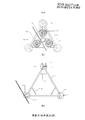
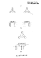
- FIG. 1 is a plan view showing a floating platform of a prestressed (lightweight) concrete three-floating offshore fan according to an embodiment of the present invention
- Figure 2 is a front elevational view of the floating platform of the three-float offshore fan of Figure 1;
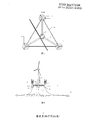
- Figure 3 is the three-buoy offshore fan floating platform of Figure 1 combined with the application number No.
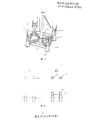
- FIG. 4 is a plan view showing a floating platform of a three-buoy offshore wind turbine according to another embodiment of the present invention.
- Figure 5 is a front elevational view of the floating platform of the three-buoy offshore fan of Figure 4 in another embodiment of the present invention.
- Figure 6 is a perspective view of the floating platform of the three-buoy offshore fan of Figure 4 in another embodiment of the present invention.
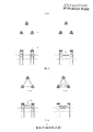
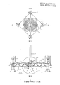
- FIG. 7 is a plan view showing a floating platform of a four-buoy offshore wind turbine according to an embodiment of the present invention.
- Figure 8 is a front elevational view of the floating platform of the four-buoy offshore fan of Figure 7;
- Figure 9 is a perspective view of the floating platform of the four-float offshore fan of Figure 7;
- FIG. 10 is a plan view showing a floating platform of a four-buoy offshore wind turbine according to another embodiment of the present invention.
- Figure 11 is a front elevational view of the floating platform of the four-buoy offshore fan of Figure 10;
- Figure 12 is a perspective view of the floating platform of the four-buoy offshore fan of Figure 10;
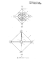
- Figure 13 is a plan view showing a floating platform of a five-float offshore wind turbine according to an embodiment of the present invention.
- Figure 14 is a front elevational view of the floating platform of the five-float offshore fan of Figure 13;
- Figure 15 is a perspective view of the floating platform of the five buoy offshore fan of Figure 13;
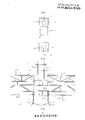
- Figure 16 shows the construction method and sequence of the three-floating fan floating platform
- Figure 17 shows the construction method and sequence of the three-floating fan floating platform
- Figure 18 shows the construction method and sequence of the three-floating fan floating platform
- Figure 19 shows the construction method and sequence of the three-floating fan floating platform
- Figure 20 shows the construction method and sequence of the three-floating fan floating platform
- Figure 21 shows a conventional design plane of an application example of a five-float floating platform
- Figure 22 is a cross-sectional view showing the application example of the five-float floating platform of Figure 21 taken along the line 1-1;
- Figure 23 is a cross-sectional view showing the application example of the five-float floating platform of Figure 22 taken along the direction 2-2;
- Figure 24 is a cross-sectional view showing the application example of the five-buoy floating platform of Figure 22 taken along the 3-3 direction;
- Figure 25 is a cross-sectional view showing the application example of the five-float floating platform of Figure 22 taken along the 4-4 direction;
- Figure 26 is a cross-sectional view showing the application example of the five-float floating platform of Figure 22 taken along the 5-5 direction;
- Figure 27 is a cross-sectional view showing the application example of the five-float floating platform of Figure 22 taken along the 6-6 direction;
- Figure 28 shows a particular connection of the center pontoon in the application example setup of the five pontoon floating platform of Figure 21.
- Wave energy generator 22 Wave energy generator support beam
- the offshore wind turbine floating platform of the present invention will be described in detail in conjunction with the preferred embodiments. Although the exemplary embodiments have been described in detail, for the sake of clarity, those skilled in the art that the present invention is not critical are not shown.
- the main material of the floating platform of the present invention refers to prestressed concrete or prestressed lightweight concrete or prestressed fiber concrete or a combination of the three.
- the various prestressed concrete materials shown above are used as examples only, and are not intended to limit the invention, as long as other materials capable of implementing the invention (eg, novel composite materials) may be employed without departing from the scope of the invention. Instead of the various prestressed concrete materials listed above.
- the pontoon in the present invention refers to a hollow cylinder or a hollow polygonal cylinder.
- prestressed concrete floating platform of the present invention is not limited to the precise embodiments described below, as those skilled in the art can change and improve without departing from the spirit and scope of the protection.
- elements and/or features depicted in different embodiments may be combined and/or substituted for each other, as long as the hollow cylinder and the hollow polygonal cylinder are interchangeable without departing from the scope of the disclosure.
- the basic three pontoon configuration has three pontoons having a diameter of 8 meters to 10 meters, respectively disposed at the vertices of the triangles, and connected to each other through the frame structure to form a triangular-shaped division structure.
- the triangular division structure referred to herein refers to a single triangular structure which is a constituent unit of the combined structure, and other structures described below may include two or more triangular division structures.
- the tower of the horizontal axis fan is erected on a substrate of the platform supported by a frame of beams and rods and located at the center of gravity of the platform.
- a vertical axis fan is erected on each pontoon as an optional setting.
- the platform shown in Figure 3 incorporates a wave energy generator.
- the wave energy generator is No. A wave energy generator described in Chinese Patent Application No. 201120134135.1 and No. 201120038156.0.
- the pontoon 31 supporting the fan tower is larger (diameter 12 to 14 meters), and the other two pontoons are smaller (8 to 10 meters in diameter) ).
- a concrete frame structure or truss is used to join the buoys to form a triangular structure. It is necessary to provide a shorter reinforcing rod at a quarter of the distance from the pontoon.
- the three pontoon floating platform can support one horizontal axis fan and two vertical axis fans.
- Each pontoon is provided with two mooring anchor chains extending from the pontoon to the sea floor for anchoring.
- Figures 7-9 show that the triangular structure is a four pontoon setting. It consists of a larger central pontoon (12m to 14m in diameter) and a smaller satellite pontoon (8m to 10m in diameter). Among them, the center buoy is placed at the center of gravity of the platform, and is connected to the satellite buoy by a Y-shaped frame structure with an angle of 120°. In order to complete the triangular division structure, a steel cable is used to connect the satellite buoys. A horizontal axis fan is mounted on the center pontoon and a vertical axis fan is mounted on each satellite pontoon. Each pontoon is provided with two mooring anchor chains extending from the pontoon to the sea floor for anchoring.
- the four pontoon structure has four pontoons, respectively disposed at the vertices of the rectangle, and connected by a frame structure to form a rectangular structure with a prestressed cable connection between each pair of diagonal pontoons. .
- the tower of the horizontal axis fan is erected on one of the pontoons.
- at least one of the remaining floats is provided.
- the pontoons with horizontal axis fans are larger in size (12 to 14 meters in diameter) and the other pontoons are smaller (8 to 10 meters in diameter).
- Each pontoon is provided with two mooring anchor chains extending from the pontoon to the sea floor for anchoring.
- the five pontoon structure has a central pontoon (12m to 14m in diameter) and four satellite pontoons (8m to 10m in diameter) at the center of gravity of the platform.
- four satellite buoys are respectively arranged at the vertices of the rectangle, and are connected to the central buoy along the diagonal of the rectangle through the frame structure.
- the prestressed cable connects the adjacent two floats along the sides of the rectangle to complete the triangle division.
- the tower of the horizontal axis fan is erected on the center pontoon.
- at least one of the remaining pontoons is provided with a vertical axis fan.
- the pontoon that supports the horizontal axis fan is larger than the other pontoons to carry heavier horizontal axis fans.
- Each pontoon is provided with two mooring anchor chains extending from the pontoon to the sea floor for anchoring.
- 16-20 illustrate a method of constructing a floating platform, which will be described in detail below.
- the floating platform is used to support a solar generator installed on the roof structure covering the central area of the platform.
- Solar panels are mounted on the ceiling.
- the solar panels need to be placed at an optimal angle relative to the sun, the floating platform tends to rotate away from the optimal angle, so it is impractical to fix the solar panels so that they do not tilt. Therefore, the solar panel is horizontally set in this step so that it is independent of the rotation of the platform.
- 21-28 show a preferred embodiment, which will be described in detail below.
- the working principle of the floating platform is based on the stability of the platform, with a minimum of three structures that are not in the same straight line.
- the conventional material for making a float is steel. It can be made of prestressed concrete or prestressed lightweight concrete as long as it is properly designed.
- the hollow cylindrical shell is suspended in water and will be subjected to loads of water pressure and wave pressure.
- the static pressure at a depth of 10 meters is 100 kN/m2. Equivalent to the load generated by the wheels of heavy trucks. This pressure will produce a large bending moment if loaded onto the plate, but in a hollow cylindrical housing, the hydrostatic pressure mainly causes the circumferential pressure. Concrete performs better in terms of pressure, and steel plates perform poorly in terms of stress.
- the static pressure is 100 kN/m2. If the wall thickness of the prestressed (lightweight) concrete hollow cylindrical shell is 300 mm, the pressure strength generated on the casing is 4N/mm2. This value is perfectly acceptable for prestressed (lightweight) concrete structures.
- the prestressed (lightweight) concrete structure is heavy, it will increase the mooring load and size, but the heavier structure will reduce the center of gravity of the entire structure. A lower center of gravity will contribute to the stability of the platform.
- the base of the platform should be at least 0.7 times the height of the tower, making the platform more stable and limiting bumps (rotation of the tower in the direction of the wind) and turning (rotation of the tower perpendicular to the direction of the wind).
- a mooring chain attached to the satellite pontoon provides a significant recovery torque to limit off-angle motion (rotational motion about the axis of the tower).
- the material damping of prestressed (lightweight) concrete is higher than that of steel, which will help to reduce the vibration of the structure and improve the fatigue resistance of the structural part.
- the damper plate provided at the bottom of the pontoon and the thickening treatment of the concrete surface will further improve the damping coefficient of the entire structure, thereby contributing to the improvement of the dynamic stability of the platform.
- the design life of prestressed (lightweight) concrete structures is typically 100 years or more, while the life of offshore wind turbines is approximately 25 years.
- the basic maintenance cost of the prestressed (lightweight) concrete structure during the life of the first installed fan is almost zero. As the structure with the least maintenance cost, it will also be serviced in the next 25 years of the second wind turbine. As long as a certain level of daily inspection and maintenance is carried out, it can also be serviced during the service life of the third and fourth fans. Routine maintenance is mainly for mechanical and electronic components of offshore wind turbines and floating platforms.
- One of the pontoons is provided with a berthing facility with a ladder leading to the top of the pontoon, and maintenance personnel can enter the machine and control room and eventually reach the top of the tower.
- Safety guardrails and safety rails are provided on the top surface of the beam as safety accessories to facilitate maintenance personnel to walk between the floats or, as an alternative, to enlarge the beams so that their internal space acts as a passage between the floats.
- the machine and control room should have facilities that allow maintenance personnel to stay and communicate for a short period of time during remote maintenance or in inclement weather.
- Sensors are installed in the air chamber and in the beam to detect flooding in any direction. Sensors for monitoring structural performance, including the state of concrete integrity, should be installed for structural health monitoring.
- the risks are classified according to the results of the accident.
- the first level of risk is that the floating platform is disconnected from the mooring chain and drifts away from the original anchor point.
- the second level of risk is an impact with the ship.
- the third level of risk is that the blades and towers are damaged in inclement weather. Other risks are the impact on navigation, shipping and fisheries, which can be handled in the usual way.
- two mooring anchor chains are used on each pontoon for redundant setup.
- the first cable is tighter than the second cable, so the second cable has a larger capacity. Therefore, when the first cable is broken, a second cable having a larger capacity will be put into use.
- the last way to prevent it from harming the public is to sink the platform to the bottom of the sea. If the depth of the seabed is less than 100 meters, the fan hub is still above the water surface, so that the fan can be recovered for maintenance.
- the invention also provides a prestressed (lightweight) concrete floating platform installation method for a floating wind farm.
- Suspended offshore wind farms include multiple floating platforms moored in open seas.
- prestressed (lightweight) concrete floating platforms Casting can be carried out in a conventional manner on land conditions on a dry dock.
- the method presented here (Figs. 16-20) is not done in the dry dock, but in the dock or port side segment prefabrication method to build the floating platform, so this novel method is called prestressed (lightweight) concrete float Platform section construction "wet method”.
- a prefabricated portion 53 is prepared in which a segment matching prefabrication is performed between the two planes using a shear key, which is a common method in bridge construction.
- the guide pile 51 for controlling the position of the pontoon penetrates into the seabed.
- These guide piles have mechanisms for supporting the drop-in positioning steel frame to secure the level and position of the float.
- the pontoon 53 constructed by the segment prefabrication unit includes a damper plate 54 provided with a guide pile opening, and the pontoon 53 constructed by the segment prefabrication unit is hoisted to the guide pile 51 by means of a floating crane.
- the positioning steel truss 52 (the column supported on the guiding pile 51 and the space truss) is also lowered and fixed on the guiding pile 51.
- the pontoon 53 constructed by the segment prefabrication unit is then hoisted from the positioning steel truss 52 to a position by the sling 55 and fixed at this position, so that the connection of the prefabricated frame structure 57 portion and the construction of the segment prefabricated unit are constructed.
- the construction of the pontoon 53 is carried out under dry conditions on the water.
- the frame structure segment 56 is also transported to the port side.
- a floating crane is used, hoisted and placed in the corresponding connection position of the pontoon 53, and then the pre-stressed and anchored joints are used to connect and fix the joint.
- the floating platform is completed. The floating platform is free after the locking device is removed and the positioning steel truss 52 is removed.
- Offshore construction installations include mooring anchor chains and mooring systems for towing embedded anchors.
- Wind farms supported by floating platforms made of pre-stressed (lightweight) concrete can significantly reduce the cost of offshore wind farms, thereby eliminating barriers to implementation. It opens up opportunities to develop wind energy in intermediate water depths and deep waters (water depths of 20 to 100 meters or more). For countries without steel mills, wind energy can be obtained from offshore wind farms, breaking the monopoly of some big countries and further To promote the application of offshore wind farms, the floating platform can also develop marine pastures and wave energy and ocean solar energy, saving energy and reducing emissions and ocean and island economic benefits.
- offshore wind farms can be developed as eco-tourism sites.
- the prestressed (lightweight) concrete five pontoon platform has a central pontoon with a center pontometer diameter of 12 m, a height of 21 m, a wall thickness of 0.3 m to 0.4 m, and a top plate of 0.5 m and a bottom plate of 0.4 to 0.75 m.
- the bottom plate extends beyond the damper plate having a diameter of 18 m.
- a 10 m short length concrete tower was cast on the center pontoon.
- a leg is provided at the top for anchoring the steel tower foundation to which the anchor is pre-installed.
- a safety work platform is placed on top of the concrete tower.
- For a 5 MW fan it weighs more than 200 tons and the rotor has a diameter of 120 meters, at which point the tower has a height of 90 meters. Together with the steel tower, the total weight of the fan will be between 700 and 1000 tons.
- the four satellite buoys are 8 meters in diameter and 23 meters in height, respectively placed at the apex of the rectangle of 70.7x70.7m, ie the diagonal length is 100 meters.
- the wall thickness of the pontoon is 0.3 to 0.4 meters at the bottom.
- the top plate has a thickness of 0.3 m to 0.5 m and the bottom plate is 0.3 m to 0.6 m.
- the bottom plate extends outward to form a damper plate having a diameter of 18 meters.
- the diagonal length between the center buoy and the satellite buoy is 50 meters.
- a pre-stressed (lightweight) concrete frame is used to connect each of the two floats.
- the top and bottom beams are 3mx3m hollow components, allowing maintenance personnel to move within the hollow area of the top beam and the hollow section of the bottom beam to accommodate air to provide additional buoyancy.
- Figure 21 shows a top plan view of the five pontoon settings.
- the platform comprises a central pontoon 31 having a diameter of 12 meters and a height of 21 meters and four satellite pontoons 1 having a diameter of 8 meters and a height of 23 meters.
- the solar panel 49 is mounted on the top panel and is supported by beams (3, 22).
- FIG 22 shows a schematic cross-sectional view of the platform.
- the pontoon includes two waterproof portions: a machine and control room 26 and an air chamber 28.
- the beam 3 is a 3 m by 3 m hollow structure, and the diagonal bar 4 is H-shaped.
- the beam 3 serves as an internal passage 47 between the floats.
- the sill 2 is used as part of the air chamber 28 to increase buoyancy.
- a short concrete tower 20 is cast onto the pontoon to raise the height of the steel tower 5 away from the splash zone.
- FIG. 23 shows that four impellers 21 are supported on the top beam 3 and the sub-frame 22.
- the prestressed cable 35 further stabilizes the platform by triangular division.
- the blade turbine 21 is No. in the application number. It is described in Chinese Patent Application No. 201120134135.1 and No. 201120038156.0.
- Figure 24 shows a portion through the top beam 3, specifically showing the central pontoon 31 and the transverse partition 43 in the satellite pontoon 1 and the partition 46 at the concrete truss node.
- the partition has an opening in the center 45 for internal access.
- Fig. 25 shows the connection details of the center inner pontoon 31.
- the sill 2 is connected to the pontoon by a prestressed cable 38 and by an anchor 13 that passes through the pontoon prestressed anchor block 30.
- the walls of the pontoon are reinforced by a reinforced ring beam 25 having a depth of 2.0 meters.
- Figure 26 shows the connection details of the pontoon inside the satellite. The joining is accomplished by combining the concrete anchor block 30, the prestressed cable 38, the anchor 13 and the reinforcing ring beam 25.
- Figure 27 shows a schematic cross-sectional view of a concrete truss.
- Figure 28 shows the connection of the beam (2, 3) to the central pontoon using a prestressing method.
- the prestressed cable 38 is installed in the beam and pulled from the inside of the pontoon, and the anchoring tension of each beam end is balanced by the reinforcing ring beam 25 and the plate 43.
- the top beam 3 serves as an internal passage 47 in which a manhole is placed and a hatch 45 is provided.
- the sill 2 serves as part of the air chamber 28 and has an open passage 44 in the pontoon wall.
- the short concrete tower 20 is about 10 meters and is poured on top of the pontoon.
- the steel tower is anchored to the concrete short tower by the anchor 11, and the working platform 17 and the guardrail 19 are provided.
- the damper plate 10 has a diameter of about 18 meters and can be installed as a stiffener of the beam at the bottom of the pontoon or at the bottom beam.
- the mooring anchor chain 6 is attached to the pontoon.
- the solar panel 49 is mounted on a top panel that is supported by the sub-frame 50 on the top rail.
Landscapes
- Engineering & Computer Science (AREA)
- Combustion & Propulsion (AREA)
- Mechanical Engineering (AREA)
- Chemical & Material Sciences (AREA)
- Ocean & Marine Engineering (AREA)
- Fluid Mechanics (AREA)
- Physics & Mathematics (AREA)
- Architecture (AREA)
- Civil Engineering (AREA)
- Structural Engineering (AREA)
- Life Sciences & Earth Sciences (AREA)
- Sustainable Development (AREA)
- Sustainable Energy (AREA)
- General Engineering & Computer Science (AREA)
- Wind Motors (AREA)
Abstract
一种半潜式的浮式平台,包括至少三个空心圆柱体混凝土浮筒(1),通过横向框架结构连接各浮筒,以形成平面为三角形或四边形或多边形结构。该浮式平台采用预应力混凝土和/或预应力轻质混凝土和/或预应力纤维混凝土制成。每个平台安装一个水平轴风机和/或至少一个垂直轴风机(41),及可选择安装太阳能(49)和/或波浪能发电机。还公开来了一种支撑海上风机的预应力混凝土浮式平台的施工安装方法。混凝土浮式平台与钢浮式平台相比,造价大幅降低,结构重心低,结构稳定性更高。平台施工安装方法类似于成熟的分段预制拼装预应力混凝土桥节段施工法。该平台应用于水深25米至100米或者更深的海上风电和海洋绿色能源开发中。
Description
相关申请的交叉引用
本申请主张申请号为CN
2011102849315、申请日为2011年9月22日、题目为“海上风电和海浪发电的悬浮预应力混凝土支撑结构和基础”的中国专利申请的优先权。本文将享有上述申请的全部权益,且上述申请以引用的方式整体并入到本文中。
本发明涉及支撑海上风电和波浪能及太阳能发电机的混凝土半潜式的浮式平台,尤其涉及一种采用预应力混凝土或预应力轻质混凝土或预应力纤维混凝土或上述组合制成的浮式平台、以及它们的建造和施工方法。
目前用在浅水区的海上风机支撑结构和基础主要为桩基础或重力式基础。30米至50米中度深水区使用桁架型导管架(Jacket)基础。深水区(60米深或更深)使用底部固定型基础太过昂贵,因此需要找到一种新型的基础。基于半潜式概念,现有技术包括欧洲的蓝H集团(Blue
H Group)的张力腿浮式平台(Tensioned Legs
Platform)以及世界第一风电机组制造商丹麦的维斯塔斯(Vestas)和美国原理电力公司(PRINCIPLE POWER
INC)在欧洲2011年11月建成的海上风电钢浮式平台
WindFloat(三角形钢浮筒)。目前所有这些海上风电浮式平台都由钢材制成。每个钢浮式平台支撑约2兆瓦的海上风机。应用5兆瓦或更大兆瓦海上风机,其所受到的风力载荷比2兆瓦的海上风机也将相应地增加数倍。水面以上100米处的风力载荷在5兆瓦风机三个风机叶片的表面上产生的风机塔底部倾覆弯矩是相当巨大的。风机的大尺寸还意味着机舱的质量要更重,当与质量较轻的钢浮式平台结合时,将导致结构重心太高,从而无法达到足够的结构稳定。而采用预应力混凝土浮式平台可降低整个系统的重心,从而提高了稳定性。
本发明提供了一种由预应力混凝土或预应力轻质混凝土或预应力纤维加强型混凝土制成的浮式平台。浮式平台包括至少三个半潜式的悬浮空心圆柱体(以下称为浮筒),各浮筒通过多个框架结构相互连接,通过横向框架结构连接各浮筒以形成平面为三角形或四边形或多边形结构。每个浮式平台安装一个水平轴风机和/或至少一个垂直轴风机及可选择安装太阳能和/或波浪能发电机。每个浮式平台包括至少三个浮筒,以形成平面为三角形或四边形或多边形的平台结构以作为基本单元,基于该基本单元还可选择构建更加复杂的相互联结的至少三个浮式平台海上风电场,以增加多平台体系抗风浪的稳定性。在对称设计中,风机塔设置在浮式平台的平面重心处;非对称设计,风机塔设置在浮式平台平面的非重心处。
本发明的三浮筒三角形浮式平台,水平轴风机设置在浮式平台的平面重心处,并通过连结梁或框架杆件支撑风机塔和风机。
本发明的另一种由四个浮筒组合形成平面为正方形的浮式平台,沿该正方形各边长连接各浮筒的框架杆件,框架结构由空心或实心或两者组合的梁和杆件组成。并通过设置在正方形对角线的预应力拉索使得正方形浮式平台更稳定。用于支撑水平轴风机的浮筒尺寸更大。其余3个浮筒支撑3台垂直轴风机。
本发明的第3种五浮筒正方形浮式平台,由四个卫星浮筒设置在平面正方形的四个角点处,第五个浮筒设置在平面正方形的重心处。框架结构沿正方形对角线连接中心浮筒与四个卫星浮筒。通过预应力拉索沿正方形的四边连接四个卫星浮筒使得五浮筒正方形浮式平台更稳定。
为了减少维修人员在浮筒之间活动带来的危害,各浮筒的顶梁可用平面较大的空心杆件,以利于维修人员在浮筒之间行走。为了增加平台的浮力,各浮筒的底梁也可应用空心杆件。
为了减少钢制的风机塔的腐蚀,尤其是减少风机塔与浮筒之间的连接的腐蚀,可优选设置(例如浇注)短钢筋混凝土塔和较长的钢风机塔相结合,该短的混凝土塔在浪溅区以上具有一定的高度,例如大约10米。
在本发明的优选方面中,该平台还设有用于在紧急情况下下沉该平台的装置,例如,当平台的系泊锚链断裂而使平台自由漂浮在水面上时,为了避免对公众造成危害,该装置将下沉平台。相反地,该装置能够上浮平台。每个浮筒设有防水的机器室和控制室及空气室。水泵安装在机器室中,并通过与管道连接而接入到位于空气室的最低点的进出水口,并在浮筒的下部与海水相通。通过控制阀门将水从海里压入到空气室中以及将水从空气室压入海里。通风管开口设置在风机塔的顶部,同样通过控制阀门来实现打开或关闭。打开通风口时,下沉操作中进入的水可将空气室中的空气排出。当半潜在海中时,阀门将关闭。在平台上升之前需要将阀门移到水面以上,使得空气能够压入空气室来取代水。如果下沉之后通风管开口在水面以上,只需简单地打开阀门让空气进入空气室即可。泵的电源来自维修船,其在系泊浮筒处具有电极端口,例如位于塔的1/3、2/3高度处或塔的顶部,以方便维修人员连接这些端口。因为采用空心梁连接浮筒,因此也将空心梁作为空气室,这样压入的水将环绕浮体,这样即使是针对一个浮筒进行泵压水操作,整个平台也不会出现严重的倾斜。
本发明的另一可选择应用,由浮式平台顶部的连结杆件支撑波浪能发电机。浮式平台还可以安装申请号分别为No.
201020134135.1和No.201120038156.0的中国专利申请中描述的大功率可变翼海浪波能发电机。该大功率可变翼海浪波能发电机水平设置,从而在波浪上下运动中通过该发电机实时捕获波浪能。
本发明的又一可选择应用为太阳能发电机安装在波浪能发电机之上,并覆盖位于钢框的顶板上的平台的中心部分。
下面将结合附图及实施例对本发明作进一步说明,附图中:
图1是本发明实施例的预应力(轻质)混凝土三浮筒海上风机浮式平台的平面示意图;
图2是图1中三浮筒海上风机浮式平台的正面示意图;
图3是图1中的三浮筒海上风机浮式平台结合了申请号分别为No.
201020134135.1和No.201120038156.0的中国专利申请中描述的波浪能发电机后的平面示意图;
图4是本发明另一实施例的三浮筒海上风机浮式平台的平面示意图;
图5是图4中本发明另一实施例的三浮筒海上风机浮式平台的正面示意图;
图6是图4中本发明另一实施例的三浮筒海上风机浮式平台的立体示意图;
图7是本发明实施例中四浮筒海上风机浮式平台的平面示意图;
图8是图7中四浮筒海上风机浮式平台的正面示意图;
图9是图7中四浮筒海上风机浮式平台的立体示意图;
图10是本发明另一实施例中四浮筒海上风机浮式平台的平面示意图;
图11是图10中四浮筒海上风机浮式平台的正面示意图;
图12是图10中四浮筒海上风机浮式平台的立体示意图;
图13是本发明实施例中五浮筒海上风机浮式平台的平面示意图;
图14是图13中五浮筒海上风机浮式平台的正面示意图;
图15是图13中五浮筒海上风机浮式平台的立体示意图;
图16示出了三浮筒风机浮式平台的建造方法和顺序;
图17示出了三浮筒风机浮式平台的建造方法和顺序;
图18示出了三浮筒风机浮式平台的建造方法和顺序;
图19示出了三浮筒风机浮式平台的建造方法和顺序;
图20示出了三浮筒风机浮式平台的建造方法和顺序;
图21示出了五浮筒浮式平台的应用实例的常规设计平面;
图22示出了图21中五浮筒浮式平台的应用实例设置沿1-1方向的剖视图;
图23示出了图22中五浮筒浮式平台的应用实例设置沿2-2方向的剖视图;
图24示出了图22中五浮筒浮式平台的应用实例设置沿3-3方向的剖视图;
图25示出了图22中五浮筒浮式平台的应用实例设置沿4-4方向的剖视图;
图26示出了图22中五浮筒浮式平台的应用实例设置沿5-5方向的剖视图;
图27示出了图22中五浮筒浮式平台的应用实例设置沿6-6方向的剖视图;
图28示出了图21中五浮筒浮式平台的应用实例设置中中心浮筒的具体连接。
附图编号:
1. 浮筒 2. 底梁
3. 顶梁 4. 对角杆件
5. 风机塔 6. 系泊锚链
7. 海床 8. 水平面
9. 用于风机支撑的脚梁 10. 阻尼板
11. 风机到浮筒的连接 12. 撑杆到风机的连接
13. 预应力锚碇
17. 工作平台 18. 开向浮筒的门
19. 护栏 20. 混凝土塔
21. 波浪能发电机 22. 波浪能发电机支撑梁
25. 浮筒加强环梁 26. 机器和控制室
28. 空气室 30. 浮筒预应力锚固块
31. 中心浮筒(用于直接支撑风机) 32. 浮筒的锥形基础
33. 浮筒的锥形基础
35. 稳定拉索(顶部) 36. 稳定拉索(底部)
37. 支撑 38. 预应力钢索
41. 垂直轴风机 42. 垂直轴风机
43. 横隔板 44. 空气室的舱门
45. 舱门入口 46. 隔板
47. 内部通道
49. 太阳能板 50. 太阳能板支撑
51. 用于构建平台的引导桩
52. 定位钢桁架-支撑在引导桩上的柱子,以及空间桁架
53. 通过节段预制单元构建的浮筒
54. 设有引导桩开口的阻尼板
55. 来自空间桁架的吊索以支撑浮筒
56. 框架结构分段
57. 预制拼装框架结构
58. 补缺阻尼板开口
为了使本发明的目的、技术方案及优点更加清楚明白,以下结合附图及实施例,对本发明进行进一步详细说明。应当理解,此处所描述的具体实施例仅用以解释本发明,并不用于限定本发明。
将结合优选实施例对本发明中的海上风机浮式平台进行详细描述。尽管对示范实施例进行了详细的描述,但是为了清楚起见,那些对本领域技术人员理解本发明不是相对重要的特征并没有示出。本发明中浮式平台的主要材料指的是预应力混凝土或预应力轻质混凝土或预应力纤维混凝土或这三种的组合。另外,以上示出的各种预应力混凝土材料仅用作举例,并不是对本发明的限制,只要不脱离本发明的保护范围,还可以采用能够实现本发明的其它材料(例如新型复合材料)来代替上述列举的各种预应力混凝土材料。本发明中的浮筒指的是空心圆柱体或空心多边形柱体。
另外,应当理解的是,本发明中的预应力混凝土浮式平台并不限于以下所描述的精确实施例,只要不脱离保护的精神和范围,本领域的技术人员可对其进行变换和改进。例如,不同实施例中描绘的元素和/或特征可以相互组合和/或相互替代,只要不脱离公开的范围,例如空心圆柱体和空心多边形柱体可互换。
如图1和图2所示,基本三浮筒配置具有三个直径为8米到10米的浮筒,分别设置在三角形的顶点处,并通过框架结构彼此连接以形成平面为三角型划分结构,此处所说的三角形划分结构指的是一个单个的三角形结构,其作为组合结构的构成单元,下面所说的其它结构有可能包括两个或两个以上的三角形划分结构。水平轴风机的塔竖立在平台的基板上,该基板通过由梁和杆件组成的框架支撑且位于平台的平面重心处。垂直轴风机作为可选择设置竖立在每个浮筒上。每个浮筒上设有两根系泊锚链,延伸至海底以进行锚固。
图3示出的平台上结合设有波浪能发电机。该波浪能发电机为申请号分别为No.
201020134135.1和No.201120038156.0的中国专利申请中描述的波浪能发电机。
如图4-6所示,在偏心的平面为三角形三浮筒中,支撑风机塔的浮筒31较大(直径为12米到14米),其它两个浮筒较小(直径为8米到10米)。混凝土框架结构或桁架用于连接各浮筒以形成三角形结构。需要在距离浮筒的1/4跨径处设置较短的加强杆件。三浮筒浮式平台上可支撑一台水平轴风机和两个垂直轴风机。每个浮筒上设有两根系泊锚链,从浮筒延伸至海底以进行锚固。
图7-9示出了三角形结构是四浮筒设置。它包括较大的中心浮筒(直径为12米到14米)和尺寸较小的多个卫星浮筒(直径为8米到10米)。其中,中心浮筒设置在平台的重心处,并通过夹角为120°的Y形框架结构与卫星浮筒连接。为完成三角划分结构,采用钢拉索连接卫星浮筒。一个水平轴风机安装在中心浮筒上,在每个卫星浮筒上安装有一个垂直轴风机。每个浮筒上设有两根系泊锚链,从浮筒延伸至海底以进行锚固。
如图10-12所示,四浮筒结构具有四个浮筒,分别设置在矩形的顶点处,通过框架结构连接以形成平面为矩形的结构,其中每对对角浮筒之间采用预应力拉索连接。水平轴风机的塔竖立在其中一个浮筒上。作为可选设置,剩余的至少一个浮筒上设有。设有水平轴风机的浮筒的尺寸较大(直径为12米到14米),其它浮筒较小(直径为8米到10米)。每个浮筒上设有两根系泊锚链,从浮筒延伸至海底以进行锚固。
如图13-15所示,五浮筒结构具有一个位于平台重心处的中心浮筒(直径为12米到14米)和四个卫星浮筒(直径为8米到10米)。其中,四个卫星浮筒分别设置在矩形的顶点处,通过框架结构沿矩形的对角线与中心浮筒连接。预应力拉索沿矩形的边连接相邻的两个浮筒以完成三角形划分。水平轴风机的塔竖立在中心浮筒上,作为可选设置,剩余的至少一个浮筒上设有垂直轴风机。支撑水平轴风机的浮筒尺寸比其它浮筒的尺寸大,从而能承载更重的水平轴风机。每个浮筒上设有两根系泊锚链,从浮筒延伸至海底以进行锚固。
图16-20示出了浮式平台的构建方法,下面将分段进行详细描述。
如图21所示,以五浮筒平台的实施例为例,浮式平台用于支撑太阳能发电机,该太阳能发电机安装在覆盖平台中心区域的顶板结构上。太阳能板安装在该顶板上。虽然太阳能板需要设置在相对太阳的最优角度下,但是浮式平台往往会旋转偏离该最优角度,因此固定太阳能板使其不发生任何倾斜是不切实际的。因此该步骤中将太阳能板水平设置,从而使其与平台的旋转无关。
图21-28示出了优选实施例,下面将分段进行详细描述。
浮式平台的工作原理
在本发明的实施例中,浮式平台的工作原理是基于平台的稳定性,最少由三个不在同一直线上的浮筒组成的结构。制造浮筒的常规材料为钢材。只要进行合适设计,能够采用预应力混凝土或预应力轻质混凝土制造。空心圆柱壳体悬浮在水中,将遭受水压和波压的载荷。10米深处的静压为100kN/m2。等效于重型卡车的轮子所产生的载荷。该压力如果加载到板上将产生巨大的弯矩,但是在空心圆柱壳体中,静水压主要导致环向压力。混凝土在承受压力方面表现较好,钢板在承受应力方面表现较差。因此,对于钢板需要关注受压屈曲不稳,需要采用多重加劲肋进行补强。对于直径为12米的圆柱壳体,在受到的静压为100kN/m2,如果预应力(轻质)混凝土空心圆柱壳体的壁厚为300毫米,此时在壳体上产生的压力强度为4N/mm2。这个值对于预应力(轻质)混凝土结构而言是完全可以接受的。
尽管预应力(轻质)混凝土结构较重,将增加系泊负载和尺寸,但是较重的结构将可以降低整个结构的重心。较低的重心将有利于平台的稳定。平台的基座尺寸应当至少为风机塔高度的0.7倍,从而使得平台更加稳定,并能限制颠簸(塔在风力方向上的转动)和翻转(塔在垂直于风力方向上的转动)。连接在卫星浮筒上的系泊锚链可以提供明显的恢复力矩,以限制偏离角度运动(绕塔的轴的转动运动)。
预应力(轻质)混凝土的材料阻尼比钢的高,这将有助于减少结构的振动以及提高结构部分的抗疲劳性能。浮筒底部设置的阻尼板以及混凝土表面的加粗处理将进一步提高整个结构的阻尼系数,从而有利于提高平台的动态稳定性能。
维护和安全测量
对于某些跨海大桥,预应力(轻质)混凝土结构的设计寿命一般为100年或以上,而海上风机的使用寿命约为25年。预应力(轻质)混凝土结构在第一个安装风机的使用期限内的基本维护费用几乎为近零。作为维护费用最少的结构,还将在第二个风机的下一个25年内服务。只要进行一定程度的日常检查和维护,还可在第三个以及第四个风机的使用期限内服务。日常维护主要是针对海上风机和浮式平台的机械机构和电子部件。
其中一个浮筒设有具有梯子的靠泊设施以通向浮筒的顶部,维修人员可进入机器和控制室并最终到达塔顶。梁的顶面上设有安全护栏和安全轨道来作为安全附件,方便维修人员在浮筒之间行走,或者作为可选,可加大梁,使其内部空间作为浮筒之间的通道。
所有的检修门都是防水的。机器和控制室应当具有在远程维护时或恶劣天气下能让维修人员短期停留以及进行通信的设施。
空气室以及梁中安装有传感器,用于检测任意方向上发生的淹没。应当安装用于监控结构性能(包括混凝土整体性的状态)的传感器以进行结构健康监控。
风险评估
依据事故的结果对风险进行分类。第一级风险是浮式平台从系泊锚链断开,并漂离原来的锚固点。第二级风险是与船发生撞击。第三级风险是在恶劣天气下,风机叶片和塔被损坏。其它的风险是对航海、航运以及渔业的影响,后二者可采用常规方法进行处理。对于第一级风险,在每个浮筒上使用两根系泊锚链来实现冗余设置。第一根缆索比第二根缆索更紧,因此,第二根缆索具有更大的容量。因此,当第一根缆索断裂后,具有更大容量的第二根缆索将投入使用。防止它对公众造成损害的最后一种方法是将平台沉没到海底。如海底的深度小于100米,风机轮毂仍然在水面以上,这样可将风机回收进行维修。
对于第二级风险,可在风机周围设置足够多的警告提醒,应当将风机刷成明亮的颜色来警示船只。类似的事故还可能由失去动力的漂浮的船只所导致,因此需要将悬浮混凝土结构设置成能抵御船只的撞击,使其只能产生局部损害。
浮式平台安装方法:
本发明还提供了一种悬浮风电场的预应力(轻质)混凝土浮式平台安装方法。悬浮海上风电场包括系泊在公开海域的多个浮式平台。
构建的开始为浇注这些预应力(轻质)混凝土浮式平台。可以常规方式在干坞上的陆上条件下实施浇注。此处所呈现的方法(图16-20)不是在干坞完成,而是在船坞或港口侧节段预制方法建造该浮式平台,因此这种新颖的方法称为预应力(轻质)混凝土浮式平台节段施工“湿法”。
该节段施工“湿法”包括以下步骤:
1.
准备预制部分53,其中采用剪力键在两个平面间实施节段匹配预制,该方法是桥梁建设中的常用方法。在船坞/港口,用于控制浮筒位置的引导桩51深入到海床中。这些引导桩具有用于支撑落入式定位钢框架的机构,从而固定浮筒的水平和位置。
2.
将浮筒部分运至港口侧,使用预应力装配上环氧树脂接头。通过节段预制单元构建的浮筒53包括设有引导桩开口的阻尼板54,采用浮吊将通过节段预制单元构建的浮筒53吊到引导桩51上。结果是,定位钢桁架52(支撑在引导桩51上的柱子以及空间桁架)也随之下降并固定在引导桩51上。
3.
随后通过吊索55将通过节段预制单元构建的浮筒53从定位钢桁架52吊起到一定位置处后固定在该位置处,使得对预制拼装框架结构57部分的连接以及通过节段预制单元构建的浮筒53的施工在水上的干燥条件下进行。
4.
与此同时,框架结构分段56也运输到港口侧。采用浮吊,吊起并放到浮筒53对应连接位置中,随后使用预应力和锚具连接和固定接头。
5. 继续操作,直到安装好所有的框架结构分段56,随后构建风机塔基础支撑57。
6. 浮式平台完成。移除锁定设备并移除所述定位钢桁架52后浮式平台自由了。
7. 补缺阻尼板54的开口,同时,海中的系泊已经准备好。
8. 完成的浮式平台自由后即可悬浮拖至海上风电场安装海域。
9. 海上施工安装包括系泊锚链和拖曳嵌入式锚的系泊系统。
10. 海上施工安装风机塔和海上风机及可选择安装太阳能和/或波浪
能发电机。
11. 对下一个平台重复以上步骤。
社会经济和环境优势及经济效益
以下将列出本发明实施例的社会经济和环境优势。通过由预应力(轻质)混凝土制成的浮式平台支撑的风电场能够显著减少海上风电场的成本,由此消除了实施的障碍。它开启了在中间水深区以及深水区(水深20米至100米或更深)发展风能的机会,对于没有钢厂的国家也能从海上风电场获取风能,打破了某些大国的垄断,能进一步推广海上风电场的应用,该浮式平台还能进行海洋牧场和波浪能及海洋太阳能等开发,节能减排和海洋及海岛经济效益巨大。
由于其位于中间水深区或深水区,进一步远离岸边,因此所产生的负面影响将更少,例如噪声。另外,平台为半潜式结构,因此对渔业的影响较小。而且,还能将海上风电场发展为生态旅游点。
应用实例
预应力(轻质)混凝土五浮筒平台具有中心浮筒,其中心浮筒的直径为12m、高度为21m、壁厚为0.3m到0.4m、以及顶板为0.5m和底板为0.4到0.75m。底板延伸到直径为18m的阻尼板之外。
10m的短长度混凝土塔浇注在中心浮筒上。在其顶部设有支腿,用于锚固预装了锚杆的钢塔基础。具有安全防护的工作平台设置在混凝土塔的顶部。对于5MW的风机,其重量超过200吨以及转子的直径为120米,此时塔的高度为90米。与钢塔一起,风机的总重量将在700吨到1000吨之间。
四个卫星浮筒的直径为8米,高度为23米,分别设置在70.7x70.7m的矩形的顶点处,即对角长度为100米。浮筒的壁厚在底部为0.3米到0.4米。顶板厚度为0.3米到0.5米,以及底板为0.3米到0.6米。底板向外延伸出去以形成直径为18米的阻尼板。
中心浮筒与卫星浮筒之间的对角长度为50米。预应力(轻质)混凝土框架用于连接每两个浮筒。顶梁和底梁为3mx3m的空心部件,使得维修人员可在顶梁的空心区域内活动以及底梁的空心区间可以容纳空气以提供额外的浮力。
图21示出了五浮筒设置的顶部平面示意图。平台包括直径为12米且高度为21米的中心浮筒31以及直径为8米且高度为23米的四个卫星浮筒1。太阳能板49安装在顶板上,其通过梁(3,22)进行支撑。
图22示出了平台的截面示意图。浮筒包括两个防水部分:机器和控制室26以及空气室28。梁3为3米乘3米的空心结构,而对角杆件4为H形。梁3用作浮筒之间的内部通道47。底梁2用作空气室28部分,以增加浮力。短混凝土塔20浇注在浮筒上,以抬高钢塔5的高度使其远离溅浪区。
图23示出了四个叶轮机21支撑在顶梁3和子框架22上。预应力拉索35通过三角形划分进一步稳定平台。叶轮机21在申请号分别为No.
201020134135.1和No.201120038156.0的中国专利申请中有描述。
图24示出了穿过顶梁3的部分,具体示出了中心浮筒31和卫星浮筒1中的横隔板43以及混凝土桁架节点处的隔板46。隔板在中心45具有开口以用于内部通入。
图25示出了中心内浮筒31的连接细节。底梁2通过预应力钢索38以及通过穿过浮筒预应力锚固块30的锚碇13与浮筒连接。浮筒的壁通过深度为2.0米的加强环梁25进行加强。
图26示出了卫星内浮筒的连接细节。通过组合混凝土锚固块30、预应力钢索38、锚碇13以及加强环梁25来完成连接。
图27示出了混凝土桁架的截面示意图。
图28示出了采用预应力方法中梁(2,3)与中心浮筒的连接。梁中安装预应力钢索38并从浮筒内部张拉,各梁端锚固张力通过加强环梁25以及板43达到平衡。顶梁3用作内部通道47,位于梁节点横隔板46设置人洞并设舱门45。底梁2用作空气室28的一部分,并在浮筒壁设开口通道44。短混凝土塔20约10米,浇注在浮筒的顶部上。钢塔通过锚杆11锚固在混凝土短塔上,并设工作平台17,及护栏19。阻尼板10的直径约为18米,安装在浮筒的底部或底梁处可作为梁的加劲肋。系泊锚链6系于浮筒。太阳能板49安装在顶板上,该顶板通过子框架50支撑在顶梁上。
Claims (23)
- 一种半潜式的浮式平台,其特征在于,包括:多个垂直布置的半潜式悬浮浮筒(1),所述浮筒(1)为空心圆柱体,以及所述浮筒相互连接并设置在水中;多个用于连接所述浮筒的框架结构以形成平面为三角形或四边形或多边形结构;多个用于连接所述浮筒的钢拉索(38);以及与所述浮式平台连接的多个系泊锚链(6)和锚碇(13),设置在水中以限制所述浮式平台的位置;其中,每个所述浮式平台包括至少三个浮筒(1)以及多个用于连接所述浮筒(1)的框架;其中配置所述钢拉索(38)连接所述浮筒(1)以形成具有三角形划分的稳定结构。
- 根据权利要求1所述的浮式平台,其特征在于,所述浮式平台上支撑有在风力作用下发电的水平轴风机。
- 根据权利要求1所述的浮式平台,其特征在于,所述浮式平台上支撑有在风力作用下发电的垂直轴风机(41)。
- 根据权利要求1所述的浮式平台,其特征在于,所述浮式平台上支撑有波浪能发电机。
- 根据权利要求1所述的浮式平台,其特征在于,所述浮式平台上连接有太阳能发电机(49)。
- 根据权利要求1所述的浮式平台,其特征在于,所述连结浮筒的框架结构包括顶梁(3)和底梁(2)、垂直短杆件或对角杆件或两者的组合。
- 根据权利要求1所述的浮式平台,其特征在于,所述浮筒(1)和/或框架结构采用预应力混凝土制成。
- 根据权利要求1所述的浮式平台,其特征在于,所述浮筒(1)和/或框架结构采用预应力轻质混凝土制成。
- 根据权利要求1所述的浮式平台,其特征在于,所述浮筒(1)和/或框架结构采用预应力纤维混凝土制成。
- 根据权利要求1所述的浮式平台,其特征在于,所述浮筒(1)和/或框架结构采用预应力钢管混凝土制成。
- 根据权利要求1所述的浮式平台,其特征在于,所述浮筒(1)和/或框架结构采用钢-混凝土组合材料制成。
- 根据权利要求6所述的浮式平台,其特征在于,所述框架结构的至少一部分杆件采用钢筋混凝土和/或钢筋轻质混凝土制成。
- 根据权利要求1所述的浮式平台,其特征在于,对所述浮式平台接触水的垂直表面进行加粗,以增加表面与水之间的摩擦力。
- 根据权利要求1所述的浮式平台,其特征在于,所述浮筒(1)的底部设有阻尼板(10),用以增加所述平台的阻尼系数,降低波浪引起的平台晃动。
- 根据权利要求1所述的浮式平台,其特征在于,每个所述浮筒(1)包括防水的机器和控制室(26)以及空气室(28);其中每个浮筒(1)设有水泵,用以将水压入所述空气室(28)以下沉所述平台,或者将水从所述空气室(28)压出以上升所述平台;所述浮筒(1)还设有从所述水泵到所述风机顶部的通气管,以使空气能进出所述空气室(28),从而实现通过控制泵压操作下沉或上升所述平台。
- 根据权利要求15所述的浮式平台,其特征在于,所述空气室(28)充有提供浮力的轻质封装材料和空气,所述轻质封装材料包括聚氨酯和泡沫块,用以永久悬浮所述平台。
- 根据权利要求6所述的浮式平台,其特征在于,所述顶梁为空心结构,以使维修人员能使用其作为浮筒(1)之间的通道。
- 根据权利要求6所述的浮式平台,其特征在于,所述顶梁和/或底梁充有提供浮力的轻质封装材料和空气,所述轻质封装材料包括聚氨酯和泡沫块,用以永久悬浮所述平台。
- 根据权利要求1所述的浮式平台,其特征在于,所述风机塔(5)支撑在中心浮筒(31)上;其中,所述中心浮筒(31)位于所述平台的重心处并通过框架结构与其它浮筒连接,所述其它浮筒为卫星浮筒。
- 根据权利要求1所述的浮式平台,其特征在于,所述风机塔(5)支撑在连接杆件节点上;其中,所述连接杆件节点位于所述平台的重心处并通过框架结构与所述浮筒(1)连接。
- 根据权利要求1所述的浮式平台,其特征在于,所述风机塔(5)支撑在所述浮式平台的其中一个所述浮筒之上,该浮筒的尺寸可比其它浮筒的尺寸大并通过框架结构与其它浮筒连接。
- 一种支撑海上风机的预应力混凝土浮式平台的施工安装方法,其特征在于,包括:在预制场或工厂内使用节段预制方法匹配浇注组成浮筒(1)的浮筒节段(53);将平台连接各浮筒(1)的框架结构分成框架结构节段(56);在预制场或工厂内使用节段预制方法匹配浇注所述框架结构节段,使用预应力逐个框架结构节段以拼装框架结构节段,完成整个预制拼装框架结构(57);在港口侧的海上插打引导桩(51),每个所述浮筒(1)对应设置至少三根引导桩(51),从而能够在港口侧的海上支撑定位钢桁架(52)以进行浮筒(1)的安装;将所述预制浮筒节段(53)运输至所述港口侧;使用预应力拼装浮筒节段(53),以完成整个浮筒的预制拼装;通过浮吊将所述完成的整个预制拼装浮筒吊至引导桩(51)的位置处,并下降所述定位钢桁架(52)以固定在所述引导桩(51)上;调节所述浮筒(1)的水平和位置,并采用所述定位钢桁架进行固定;将所述整个预制拼装框架结构(57)运输至所述港口侧;采用浮吊,将所述整个预制拼装框架结构(57)下降到与各浮筒(1)对应的接头位置处,以及通过预应力和锚具连接和固定接头;重复以上步骤到完成浮式平台的节段施工法;移除锁定设备并移除所述定位钢桁架(52);浮式平台自由后即可悬浮拖至海上风电场安装海域;在海上施工安装包括系泊锚链和拖曳嵌入式锚的系泊系统;在海上施工安装风机塔和海上风机。
- 根据权利要求22所述的一种支撑海上风机的预应力混凝土浮式平台的施工安装方法,其特征在于,所述施工安装方法进一步包括:在海上施工安装太阳能和/或波浪能发电机。
Applications Claiming Priority (2)
| Application Number | Priority Date | Filing Date | Title |
|---|---|---|---|
| CN201110284931 | 2011-09-22 | ||
| CN201110284931.5 | 2011-09-22 |
Publications (1)
| Publication Number | Publication Date |
|---|---|
| WO2013040871A1 true WO2013040871A1 (zh) | 2013-03-28 |
Family
ID=47913818
Family Applications (1)
| Application Number | Title | Priority Date | Filing Date |
|---|---|---|---|
| PCT/CN2012/071136 Ceased WO2013040871A1 (zh) | 2011-09-22 | 2012-02-14 | 支撑海上风机和海洋能发电机的预应力混凝土浮式平台 |
Country Status (1)
| Country | Link |
|---|---|
| WO (1) | WO2013040871A1 (zh) |
Cited By (60)
| Publication number | Priority date | Publication date | Assignee | Title |
|---|---|---|---|---|
| US20130233231A1 (en) * | 2010-11-04 | 2013-09-12 | University Of Maine System Board Of Trustees | Floating Wind Turbine Platform and Method of Assembling |
| GB2503104A (en) * | 2012-05-29 | 2013-12-18 | Lunar Energy Power Ltd | Submersible platform for attaching a plurality of energy producing devices |
| US20140014020A1 (en) * | 2011-03-29 | 2014-01-16 | Victor Valeryevich Cheboxarov | Wind power plant |
| DE102013222081A1 (de) * | 2013-10-30 | 2015-04-30 | Gicon Windpower Ip Gmbh | In der offenen See schwimmendes und über Abspannmittel mit Ankern verbundenes Tragwerk für Windkraftanlagen, Servicestationen oder Konverterstationen |
| CN104595127A (zh) * | 2015-01-08 | 2015-05-06 | 深圳市广发海能科技有限公司 | 一种立体三角垂轴共架构级联式发电风塔及实施方法 |
| WO2015047148A3 (en) * | 2013-09-29 | 2015-08-13 | Gox Ab | Nine-branched wind platform |
| EP2931597A4 (en) * | 2012-10-05 | 2016-07-27 | Hexicon Ab | FLOATING PLATFORM AND ENERGY PRODUCTION PLANT WITH SUCH A FLOATING PLATFORM |
| US9518564B2 (en) | 2010-11-04 | 2016-12-13 | University Of Maine System Board Of Trustee | Floating hybrid composite wind turbine platform and tower system |
| FR3051023A1 (fr) * | 2016-05-03 | 2017-11-10 | Dcns | Flotteur notamment d'eolienne offshore |
| WO2017207934A1 (fr) * | 2016-06-03 | 2017-12-07 | Dietswell | Éolienne flottante |
| DE102017204121A1 (de) | 2017-03-13 | 2018-09-13 | Gicon Windpower Ip Gmbh | Schwimmfähige Offshore-Anlage zur Umwandlung von Windenergie und/oder Sonnenenergie in elektrische Energie |
| FR3064694A1 (fr) * | 2017-03-28 | 2018-10-05 | Dcns Energies | Flotteur hybride d'eolienne |
| FR3064695A1 (fr) * | 2017-03-28 | 2018-10-05 | Dcns Energies | Flotteur hybride d'eolienne offshore |
| CN108757338A (zh) * | 2018-04-02 | 2018-11-06 | 广州航海学院 | 一种漂浮式风电场平稳与抗台的风机系统 |
| CN109982923A (zh) * | 2016-11-25 | 2019-07-05 | 日本日联海洋株式会社 | 浮体结构物 |
| CN110435839A (zh) * | 2019-09-06 | 2019-11-12 | 集美大学 | 一种漂浮式海上风光储发电系统雷达测风移动平台减摇基础承台 |
| WO2020002160A1 (de) * | 2018-06-26 | 2020-01-02 | Universitaet Stuttgart | Schwimmtragwerk für eine windkraftanlage |
| CN111301622A (zh) * | 2020-03-25 | 2020-06-19 | 天津大学 | 一种可迁移的海上风电浮式基础及其作业方法 |
| CN111391987A (zh) * | 2020-03-30 | 2020-07-10 | 清华大学深圳国际研究生院 | 中等深度水域的浮式风机装备 |
| CN112610426A (zh) * | 2020-12-30 | 2021-04-06 | 中国华能集团清洁能源技术研究院有限公司 | 一种海上半潜式风机基础及风力发电机组 |
| CN112606962A (zh) * | 2020-12-29 | 2021-04-06 | 中国长江三峡集团有限公司 | 集成电化学储能装置的海上风电浮式基础 |
| GB2589641A (en) * | 2019-12-06 | 2021-06-09 | Marine Power Systems Ltd | Buoyant platform |
| WO2021111138A1 (en) * | 2019-12-06 | 2021-06-10 | Marine Power Systems Limited | Buoyant platform |
| FR3108953A1 (fr) | 2020-04-06 | 2021-10-08 | Olivier JUIN | Structure porteuse d’installation de modules de captage d’energie eolienne |
| US11203398B2 (en) * | 2017-11-21 | 2021-12-21 | Axis Energy Projects Group Limited | Buoy and installation method for the buoy |
| CN113864128A (zh) * | 2021-10-27 | 2021-12-31 | 上海电气风电集团股份有限公司 | 海上风机支撑结构以及海上风机 |
| CN113915070A (zh) * | 2021-10-18 | 2022-01-11 | 上海电气风电集团股份有限公司 | 一种梁型海上浮式风力涡轮发电系统 |
| US11225945B2 (en) | 2019-05-30 | 2022-01-18 | Principle Power, Inc. | Floating wind turbine platform controlled to optimize power production and reduce loading |
| CN114179984A (zh) * | 2021-12-16 | 2022-03-15 | 长沙紫宸科技开发有限公司 | 一种海洋抗浪平台 |
| US20220128033A1 (en) * | 2019-02-15 | 2022-04-28 | Northeastern University | Shallow draft, wide-base floating wind turbine without nacelle |
| CN114572356A (zh) * | 2022-03-25 | 2022-06-03 | 重庆大学 | 一种钢-混凝土混合结构漂浮式风电基础 |
| CN115107939A (zh) * | 2021-03-23 | 2022-09-27 | 惠生(南通)重工有限公司 | 海上浮式风电组合式半潜平台基础及其安装方法 |
| GB2605616A (en) * | 2021-04-07 | 2022-10-12 | Marine Power Systems Ltd | Mooring arrangement for a tension leg platform |
| US20220325697A1 (en) * | 2021-04-09 | 2022-10-13 | Guangzhou Institute Of Energy Conversion, Chinese Academy Of Sciences | Deep-sea multi-energy integrated platform for complementary power generation, production, living and exploration |
| CN115258072A (zh) * | 2022-08-16 | 2022-11-01 | 山东电力工程咨询院有限公司 | 风、光、波、渔互补的混凝土浮式综合装置及作业方法 |
| AU2022218537A1 (en) * | 2022-08-17 | 2022-11-03 | Thanh Tri Lam | System of three-dimensional flexible porous net of multiple floating objects |
| CN115503896A (zh) * | 2022-07-07 | 2022-12-23 | 大连船舶重工集团有限公司 | 一种带运动抑制舱的浮式风力发电平台 |
| CN115571285A (zh) * | 2022-08-26 | 2023-01-06 | 上海交通大学 | 一种海上浮式光伏平台 |
| WO2023009010A1 (en) * | 2021-07-30 | 2023-02-02 | Aker Offshore Wind Operating Company As | Floating wind turbine platform |
| CN115750211A (zh) * | 2022-11-23 | 2023-03-07 | 华南理工大学 | 一种基于导管架平台的波浪能-风能发电装置集成系统 |
| CN115743460A (zh) * | 2022-11-23 | 2023-03-07 | 广州文船重工有限公司 | 一种海上浮式风电平台的施工方法 |
| CN116001999A (zh) * | 2022-12-12 | 2023-04-25 | 上海勘测设计研究院有限公司 | 一种海上浮式平台装置以及施工方法和工作方法 |
| WO2023144425A1 (es) * | 2022-01-28 | 2023-08-03 | Acciona Construccion, S.A. | Plataforma semisumergible |
| CN116552698A (zh) * | 2023-04-14 | 2023-08-08 | 江苏大津重工有限公司 | 一种用于海洋平台风机叶片堆放的可拆卸式贝雷架结构 |
| IT202200004748A1 (it) * | 2022-03-11 | 2023-09-11 | Fincantieri Spa | Galleggiante per il supporto di un generatore eolico offshore |
| WO2023198137A1 (zh) * | 2022-04-15 | 2023-10-19 | 中国华能集团清洁能源技术研究院有限公司 | 一种具有主动压舱装置的漂浮式风机 |
| CN117002689A (zh) * | 2023-06-29 | 2023-11-07 | 华中科技大学 | 一种变直径重心可调型漂浮式spar风电平台 |
| CN117166439A (zh) * | 2023-09-07 | 2023-12-05 | 中国长江三峡集团有限公司 | 海底轻量化升压站装置及海上发电系统 |
| CN117227919A (zh) * | 2023-10-24 | 2023-12-15 | 中国船舶集团有限公司第七〇八研究所 | 一种适用于高海况的高航速半潜平台 |
| CN117378545A (zh) * | 2023-11-10 | 2024-01-12 | 中交天津港湾工程设计院有限公司 | 一种新型升降式混凝土深水养殖平台 |
| CN117425593A (zh) * | 2021-04-06 | 2024-01-19 | 浦项股份有限公司 | 漂浮式平台及包括漂浮式平台的漂浮式海上风力发电装置 |
| NO20230217A1 (en) * | 2023-03-03 | 2024-09-04 | Ids Invest As | A floating platform for wind turbine units and a method for assemblying the platform |
| EP4193060A4 (en) * | 2020-08-04 | 2024-10-02 | Equinor Energy AS | MOORING SYSTEM FOR FLOATING WIND TURBINES |
| EP4238863A4 (en) * | 2020-10-30 | 2024-12-25 | Hyundai Heavy Industries Co., Ltd. | Floating offshore structure and floating offshore power generation apparatus having same |
| CN119348775A (zh) * | 2024-08-06 | 2025-01-24 | 哈尔滨工程大学 | 一种设计靠泊结构的混合型浮式风机基础 |
| CN119353164A (zh) * | 2024-10-17 | 2025-01-24 | 中交第四航务工程局有限公司 | 一种半潜式漂浮风机基础、系统及设计方法 |
| CN120246178A (zh) * | 2025-03-20 | 2025-07-04 | 中国铁路设计集团有限公司 | 一种重型水上浮动式平台 |
| GB2641205A (en) * | 2023-12-21 | 2025-11-26 | Aeon Energy Ltd | A renewable energy generation module |
| EP4557604A4 (en) * | 2022-07-13 | 2026-07-22 | Huaneng Clean Energy Research Inst | MULTIFUNCTIONAL INTEGRATED PLATFORM |
| US12691978B2 (en) | 2020-10-30 | 2026-07-28 | Hyundai Heavy Industries Co., Ltd. | Floating offshore structure and floating offshore power generation apparatus having same |
Citations (10)
| Publication number | Priority date | Publication date | Assignee | Title |
|---|---|---|---|---|
| DE3224976A1 (de) * | 1982-07-03 | 1984-01-05 | Erno Raumfahrttechnik Gmbh, 2800 Bremen | Windenergiekonverter im offshore-bereich |
| CN1175232A (zh) * | 1995-02-01 | 1998-03-04 | 克韦尔纳有限公司 | 浮动设备 |
| NL1008318C2 (nl) * | 1998-02-16 | 1999-08-17 | Lagerwey Windturbine B V | Windmolen-eiland. |
| US20010002757A1 (en) * | 1999-12-07 | 2001-06-07 | Mitsubishi Heavy Industries, Ltd. | Wind-powered generator plant |
| JP2007160965A (ja) * | 2005-12-09 | 2007-06-28 | Shimizu Corp | 浮体構造 |
| WO2009067023A1 (en) * | 2007-11-19 | 2009-05-28 | Windsea As | Floating wind power apparatus |
| CN101649813A (zh) * | 2009-09-09 | 2010-02-17 | 张建洲 | 水流海浪潮汐动能和风能太阳能发电的综合系统 |
| WO2010094776A1 (en) * | 2009-02-20 | 2010-08-26 | Xemc Darwind B.V. | Offshore wind park |
| JP2010280301A (ja) * | 2009-06-04 | 2010-12-16 | Shimizu Corp | 洋上施設用浮体構造物および洋上施設の施工方法 |
| CN102015435A (zh) * | 2008-04-23 | 2011-04-13 | 原理动力有限公司 | 用于支撑近海风力涡轮机的不对称系泊系统和带有水收集板的支柱稳定式近海平台 |
-
2012
- 2012-02-14 WO PCT/CN2012/071136 patent/WO2013040871A1/zh not_active Ceased
Patent Citations (10)
| Publication number | Priority date | Publication date | Assignee | Title |
|---|---|---|---|---|
| DE3224976A1 (de) * | 1982-07-03 | 1984-01-05 | Erno Raumfahrttechnik Gmbh, 2800 Bremen | Windenergiekonverter im offshore-bereich |
| CN1175232A (zh) * | 1995-02-01 | 1998-03-04 | 克韦尔纳有限公司 | 浮动设备 |
| NL1008318C2 (nl) * | 1998-02-16 | 1999-08-17 | Lagerwey Windturbine B V | Windmolen-eiland. |
| US20010002757A1 (en) * | 1999-12-07 | 2001-06-07 | Mitsubishi Heavy Industries, Ltd. | Wind-powered generator plant |
| JP2007160965A (ja) * | 2005-12-09 | 2007-06-28 | Shimizu Corp | 浮体構造 |
| WO2009067023A1 (en) * | 2007-11-19 | 2009-05-28 | Windsea As | Floating wind power apparatus |
| CN102015435A (zh) * | 2008-04-23 | 2011-04-13 | 原理动力有限公司 | 用于支撑近海风力涡轮机的不对称系泊系统和带有水收集板的支柱稳定式近海平台 |
| WO2010094776A1 (en) * | 2009-02-20 | 2010-08-26 | Xemc Darwind B.V. | Offshore wind park |
| JP2010280301A (ja) * | 2009-06-04 | 2010-12-16 | Shimizu Corp | 洋上施設用浮体構造物および洋上施設の施工方法 |
| CN101649813A (zh) * | 2009-09-09 | 2010-02-17 | 张建洲 | 水流海浪潮汐动能和风能太阳能发电的综合系统 |
Cited By (91)
| Publication number | Priority date | Publication date | Assignee | Title |
|---|---|---|---|---|
| US9394035B2 (en) * | 2010-11-04 | 2016-07-19 | University Of Maine System Board Of Trustees | Floating wind turbine platform and method of assembling |
| US20130233231A1 (en) * | 2010-11-04 | 2013-09-12 | University Of Maine System Board Of Trustees | Floating Wind Turbine Platform and Method of Assembling |
| US9518564B2 (en) | 2010-11-04 | 2016-12-13 | University Of Maine System Board Of Trustee | Floating hybrid composite wind turbine platform and tower system |
| US20140014020A1 (en) * | 2011-03-29 | 2014-01-16 | Victor Valeryevich Cheboxarov | Wind power plant |
| US9168984B2 (en) * | 2011-03-29 | 2015-10-27 | Federal Agency for Legal Protection of Millitary, Special and Dual Use Intellectual Activity Results (FALPIAR) | Wind power plant |
| GB2503104A (en) * | 2012-05-29 | 2013-12-18 | Lunar Energy Power Ltd | Submersible platform for attaching a plurality of energy producing devices |
| GB2503104B (en) * | 2012-05-29 | 2016-10-19 | Lunar Energy Power Ltd | Apparatus and method for a submersible platform having attachment means for a plurality of energy-producing devices |
| EP2931597A4 (en) * | 2012-10-05 | 2016-07-27 | Hexicon Ab | FLOATING PLATFORM AND ENERGY PRODUCTION PLANT WITH SUCH A FLOATING PLATFORM |
| WO2015047148A3 (en) * | 2013-09-29 | 2015-08-13 | Gox Ab | Nine-branched wind platform |
| DE102013222081B4 (de) * | 2013-10-30 | 2016-05-12 | Gicon Windpower Ip Gmbh | In der offenen See schwimmendes und über Abspannmittel mit Ankern verbundenes Tragwerk für Windkraftanlagen, Servicestationen oder Konverterstationen |
| US10259542B2 (en) | 2013-10-30 | 2019-04-16 | Gicon Windpower Ip Gmbh | Support structure floating in the open sea and connected to anchors by bracing means, for wind turbines, service stations or converter stations |
| DE102013222081A1 (de) * | 2013-10-30 | 2015-04-30 | Gicon Windpower Ip Gmbh | In der offenen See schwimmendes und über Abspannmittel mit Ankern verbundenes Tragwerk für Windkraftanlagen, Servicestationen oder Konverterstationen |
| CN104595127A (zh) * | 2015-01-08 | 2015-05-06 | 深圳市广发海能科技有限公司 | 一种立体三角垂轴共架构级联式发电风塔及实施方法 |
| FR3051023A1 (fr) * | 2016-05-03 | 2017-11-10 | Dcns | Flotteur notamment d'eolienne offshore |
| WO2017207934A1 (fr) * | 2016-06-03 | 2017-12-07 | Dietswell | Éolienne flottante |
| FR3052195A1 (fr) * | 2016-06-03 | 2017-12-08 | Dietswell | Eoliennes flottantes. |
| FR3052142A1 (fr) * | 2016-06-03 | 2017-12-08 | Dietswell | Flotteur a pilonnement reduit, notamment pour une eolienne flottante. |
| WO2017207937A1 (fr) * | 2016-06-03 | 2017-12-07 | Dietswell | Flotteur a pilonnement reduit, notamment pour une eolienne flottante |
| EP3546337A4 (en) * | 2016-11-25 | 2020-07-08 | Japan Marine United Corporation | FLOATING STRUCTURE |
| CN109982923A (zh) * | 2016-11-25 | 2019-07-05 | 日本日联海洋株式会社 | 浮体结构物 |
| DE102017204121A1 (de) | 2017-03-13 | 2018-09-13 | Gicon Windpower Ip Gmbh | Schwimmfähige Offshore-Anlage zur Umwandlung von Windenergie und/oder Sonnenenergie in elektrische Energie |
| WO2018166939A1 (de) | 2017-03-13 | 2018-09-20 | Gicon Windpower Ip Gmbh | Schwimmfähige offshore-anlage zur umwandlung von windenergie und/oder sonnenenergie in elektrische energie |
| DE102017204121B4 (de) | 2017-03-13 | 2020-07-09 | Gicon Windpower Ip Gmbh | Schwimmfähige Offshore-Anlage zur Umwandlung von Windenergie und/oder Sonnenenergie in elektrische Energie |
| FR3064695A1 (fr) * | 2017-03-28 | 2018-10-05 | Dcns Energies | Flotteur hybride d'eolienne offshore |
| FR3064694A1 (fr) * | 2017-03-28 | 2018-10-05 | Dcns Energies | Flotteur hybride d'eolienne |
| US11203398B2 (en) * | 2017-11-21 | 2021-12-21 | Axis Energy Projects Group Limited | Buoy and installation method for the buoy |
| CN108757338A (zh) * | 2018-04-02 | 2018-11-06 | 广州航海学院 | 一种漂浮式风电场平稳与抗台的风机系统 |
| WO2020002160A1 (de) * | 2018-06-26 | 2020-01-02 | Universitaet Stuttgart | Schwimmtragwerk für eine windkraftanlage |
| US12692839B2 (en) | 2019-02-15 | 2026-07-28 | Tows, Inc. | High capacity, shallow draft, ocean-borne wind turbine |
| US20220128033A1 (en) * | 2019-02-15 | 2022-04-28 | Northeastern University | Shallow draft, wide-base floating wind turbine without nacelle |
| US11225945B2 (en) | 2019-05-30 | 2022-01-18 | Principle Power, Inc. | Floating wind turbine platform controlled to optimize power production and reduce loading |
| CN110435839B (zh) * | 2019-09-06 | 2024-04-02 | 集美大学 | 一种漂浮式海上风光储发电系统雷达测风移动平台减摇基础承台 |
| CN110435839A (zh) * | 2019-09-06 | 2019-11-12 | 集美大学 | 一种漂浮式海上风光储发电系统雷达测风移动平台减摇基础承台 |
| WO2021111138A1 (en) * | 2019-12-06 | 2021-06-10 | Marine Power Systems Limited | Buoyant platform |
| GB2589641A (en) * | 2019-12-06 | 2021-06-09 | Marine Power Systems Ltd | Buoyant platform |
| CN111301622A (zh) * | 2020-03-25 | 2020-06-19 | 天津大学 | 一种可迁移的海上风电浮式基础及其作业方法 |
| CN111391987A (zh) * | 2020-03-30 | 2020-07-10 | 清华大学深圳国际研究生院 | 中等深度水域的浮式风机装备 |
| FR3108953A1 (fr) | 2020-04-06 | 2021-10-08 | Olivier JUIN | Structure porteuse d’installation de modules de captage d’energie eolienne |
| WO2021205293A1 (fr) | 2020-04-06 | 2021-10-14 | Juin Olivier | Structure porteuse d'installation de modules de captage d'energie eolienne |
| EP4193060A4 (en) * | 2020-08-04 | 2024-10-02 | Equinor Energy AS | MOORING SYSTEM FOR FLOATING WIND TURBINES |
| US12606276B2 (en) | 2020-08-04 | 2026-04-21 | Equinor Energy As | Mooring system for floating wind turbine |
| EP4624317A3 (en) * | 2020-10-30 | 2025-12-24 | Hyundai Heavy Industries Co., Ltd. | Floating offshore structure and floating offshore power generation apparatus having same |
| EP4628398A3 (en) * | 2020-10-30 | 2025-12-24 | Hyundai Heavy Industries Co., Ltd. | Floating offshore structure and floating offshore power generation apparatus having same |
| EP4238863A4 (en) * | 2020-10-30 | 2024-12-25 | Hyundai Heavy Industries Co., Ltd. | Floating offshore structure and floating offshore power generation apparatus having same |
| US12691978B2 (en) | 2020-10-30 | 2026-07-28 | Hyundai Heavy Industries Co., Ltd. | Floating offshore structure and floating offshore power generation apparatus having same |
| CN112606962A (zh) * | 2020-12-29 | 2021-04-06 | 中国长江三峡集团有限公司 | 集成电化学储能装置的海上风电浮式基础 |
| CN112610426A (zh) * | 2020-12-30 | 2021-04-06 | 中国华能集团清洁能源技术研究院有限公司 | 一种海上半潜式风机基础及风力发电机组 |
| CN115107939A (zh) * | 2021-03-23 | 2022-09-27 | 惠生(南通)重工有限公司 | 海上浮式风电组合式半潜平台基础及其安装方法 |
| EP4321423A4 (en) * | 2021-04-06 | 2024-10-09 | POSCO Co., Ltd | FLOATING PLATFORM AND FLOATING OFFSHORE WIND TURBINE |
| CN117425593A (zh) * | 2021-04-06 | 2024-01-19 | 浦项股份有限公司 | 漂浮式平台及包括漂浮式平台的漂浮式海上风力发电装置 |
| GB2605616A (en) * | 2021-04-07 | 2022-10-12 | Marine Power Systems Ltd | Mooring arrangement for a tension leg platform |
| US12643635B2 (en) | 2021-04-07 | 2026-06-02 | Marine Power Systems Limited | Mooring arrangement for a tension leg platform |
| CN117320955A (zh) * | 2021-04-07 | 2023-12-29 | 海洋能源系统有限公司 | 用于张力腿平台的系泊装置 |
| US20220325697A1 (en) * | 2021-04-09 | 2022-10-13 | Guangzhou Institute Of Energy Conversion, Chinese Academy Of Sciences | Deep-sea multi-energy integrated platform for complementary power generation, production, living and exploration |
| US11555478B2 (en) * | 2021-04-09 | 2023-01-17 | Guangzhou Institute Of Energy Conversion, Chinese Academy Of Sciences | Deep-sea multi-energy integrated platform for complementary power generation, production, living and exploration |
| WO2023009010A1 (en) * | 2021-07-30 | 2023-02-02 | Aker Offshore Wind Operating Company As | Floating wind turbine platform |
| GB2624582A (en) * | 2021-07-30 | 2024-05-22 | Aker Offshore Wind Operating Company As | Floating wind turbine platform |
| CN113915070A (zh) * | 2021-10-18 | 2022-01-11 | 上海电气风电集团股份有限公司 | 一种梁型海上浮式风力涡轮发电系统 |
| CN113864128A (zh) * | 2021-10-27 | 2021-12-31 | 上海电气风电集团股份有限公司 | 海上风机支撑结构以及海上风机 |
| CN114179984A (zh) * | 2021-12-16 | 2022-03-15 | 长沙紫宸科技开发有限公司 | 一种海洋抗浪平台 |
| WO2023144425A1 (es) * | 2022-01-28 | 2023-08-03 | Acciona Construccion, S.A. | Plataforma semisumergible |
| WO2023170625A1 (en) * | 2022-03-11 | 2023-09-14 | Fincantieri S.P.A. | Floater for the support of an offshore wind power generator |
| IT202200004748A1 (it) * | 2022-03-11 | 2023-09-11 | Fincantieri Spa | Galleggiante per il supporto di un generatore eolico offshore |
| CN114572356A (zh) * | 2022-03-25 | 2022-06-03 | 重庆大学 | 一种钢-混凝土混合结构漂浮式风电基础 |
| WO2023198137A1 (zh) * | 2022-04-15 | 2023-10-19 | 中国华能集团清洁能源技术研究院有限公司 | 一种具有主动压舱装置的漂浮式风机 |
| CN115503896A (zh) * | 2022-07-07 | 2022-12-23 | 大连船舶重工集团有限公司 | 一种带运动抑制舱的浮式风力发电平台 |
| EP4557604A4 (en) * | 2022-07-13 | 2026-07-22 | Huaneng Clean Energy Research Inst | MULTIFUNCTIONAL INTEGRATED PLATFORM |
| CN115258072A (zh) * | 2022-08-16 | 2022-11-01 | 山东电力工程咨询院有限公司 | 风、光、波、渔互补的混凝土浮式综合装置及作业方法 |
| AU2022218538A1 (en) * | 2022-08-17 | 2022-11-03 | Thanh Tri Lam | Net of non-horizontal connections |
| AU2022218538B2 (en) * | 2022-08-17 | 2022-12-15 | Thanh Tri Lam | Net of non-horizontal connections |
| AU2022218537A1 (en) * | 2022-08-17 | 2022-11-03 | Thanh Tri Lam | System of three-dimensional flexible porous net of multiple floating objects |
| CN115571285A (zh) * | 2022-08-26 | 2023-01-06 | 上海交通大学 | 一种海上浮式光伏平台 |
| CN115750211A (zh) * | 2022-11-23 | 2023-03-07 | 华南理工大学 | 一种基于导管架平台的波浪能-风能发电装置集成系统 |
| CN115743460A (zh) * | 2022-11-23 | 2023-03-07 | 广州文船重工有限公司 | 一种海上浮式风电平台的施工方法 |
| CN116001999B (zh) * | 2022-12-12 | 2024-03-01 | 上海勘测设计研究院有限公司 | 一种海上浮式平台装置以及施工方法和工作方法 |
| CN116001999A (zh) * | 2022-12-12 | 2023-04-25 | 上海勘测设计研究院有限公司 | 一种海上浮式平台装置以及施工方法和工作方法 |
| US12448092B2 (en) | 2022-12-12 | 2025-10-21 | Shanghai Investigation, Design & Research Institute Co., Ltd. | Offshore floating platform device, construction method and operation method |
| WO2024186215A1 (en) * | 2023-03-03 | 2024-09-12 | Ids Invest As | A floating platform for wind turbine units and a method for assemblying the platform |
| NO348353B1 (en) * | 2023-03-03 | 2024-12-02 | Ids Invest As | A floating platform for wind turbine units and a method for assemblying the platform |
| NO20230217A1 (en) * | 2023-03-03 | 2024-09-04 | Ids Invest As | A floating platform for wind turbine units and a method for assemblying the platform |
| CN116552698A (zh) * | 2023-04-14 | 2023-08-08 | 江苏大津重工有限公司 | 一种用于海洋平台风机叶片堆放的可拆卸式贝雷架结构 |
| CN117002689A (zh) * | 2023-06-29 | 2023-11-07 | 华中科技大学 | 一种变直径重心可调型漂浮式spar风电平台 |
| CN117002689B (zh) * | 2023-06-29 | 2024-01-12 | 华中科技大学 | 一种变直径重心可调型漂浮式spar风电平台 |
| CN117166439A (zh) * | 2023-09-07 | 2023-12-05 | 中国长江三峡集团有限公司 | 海底轻量化升压站装置及海上发电系统 |
| CN117227919A (zh) * | 2023-10-24 | 2023-12-15 | 中国船舶集团有限公司第七〇八研究所 | 一种适用于高海况的高航速半潜平台 |
| CN117378545A (zh) * | 2023-11-10 | 2024-01-12 | 中交天津港湾工程设计院有限公司 | 一种新型升降式混凝土深水养殖平台 |
| GB2641205A (en) * | 2023-12-21 | 2025-11-26 | Aeon Energy Ltd | A renewable energy generation module |
| CN119348775B (zh) * | 2024-08-06 | 2025-09-19 | 哈尔滨工程大学 | 一种设计靠泊结构的混合型浮式风机基础 |
| CN119348775A (zh) * | 2024-08-06 | 2025-01-24 | 哈尔滨工程大学 | 一种设计靠泊结构的混合型浮式风机基础 |
| CN119353164A (zh) * | 2024-10-17 | 2025-01-24 | 中交第四航务工程局有限公司 | 一种半潜式漂浮风机基础、系统及设计方法 |
| CN120246178A (zh) * | 2025-03-20 | 2025-07-04 | 中国铁路设计集团有限公司 | 一种重型水上浮动式平台 |
Similar Documents
| Publication | Publication Date | Title |
|---|---|---|
| CN103010415B (zh) | 支撑海上风机和海洋能发电机的预应力混凝土浮式平台 | |
| US12085057B2 (en) | Support structure for wind power generation device and wind power generation device | |
| US12030600B2 (en) | Structure for supporting marine installations and procedure for the execution thereof | |
| WO2013120264A1 (zh) | 支撑海上风机、桥梁、海洋建筑物的浮力支撑固定平台 | |
| CN104619984B (zh) | 浮式风力涡轮机平台和组装方法 | |
| US11920559B2 (en) | Floating platform for high-power wind turbines | |
| JP6163492B2 (ja) | 洋上タワーの据え付け方法 | |
| EP3584373B1 (en) | Maritime structure for laying the foundations of buildings and its method of installation | |
| KR101713618B1 (ko) | 해안 풍력 터빈의 지지를 위한 워터-엔트랩먼트 플레이트 및 비대칭 무링 시스템을 가진 칼럼-안정화된 해안 플랫폼 | |
| US9394035B2 (en) | Floating wind turbine platform and method of assembling | |
| EP3456960B1 (en) | Auxiliary floating system for the installation and/or transport of marine structures and method comprising said system | |
| CN107021190A (zh) | 可自浮安装的张力腿式海上浮动风机基础及其安装方法 | |
| US9238896B2 (en) | Floating structure for supporting a wind turbine | |
| TR201819102T4 (tr) | Açik deni̇z tesi̇si̇, bi̇r açik deni̇z tesi̇si̇ni̇n tabani ve bi̇r açik deni̇z tesi̇si̇ni̇n kurulmasina yöneli̇k yöntem | |
| WO2013044978A1 (en) | Method of building an offshore power storage facility and corresponding offshore power storage facility | |
| WO2022211639A1 (en) | Foundation for an offshore wind turbine | |
| KR20140128958A (ko) | 풍력발전용 터빈을 지지하기 위한 부유식 프리캐스트-콘크리트 구조물 | |
| CN215518693U (zh) | 一种基于单桩基础的旋转施工平台 | |
| CN119637020A (zh) | 一种适用于深远海的新型浮漂式换流站平台 | |
| CN212927260U (zh) | 一种重力式多筒基础海上测风塔结构 | |
| CN115262514B (zh) | 一种基于单桩基础的旋转施工平台 | |
| JP2024064177A (ja) | スパー型浮体を備えた洋上風力発電設備の浮体建造方法 | |
| CN211036888U (zh) | 水域桥梁柔性防撞墙 | |
| CN221393946U (zh) | 一种张紧系泊漂浮式海上光伏结构 | |
| CN219710250U (zh) | 一种快速装配式海上平台 |
Legal Events
| Date | Code | Title | Description |
|---|---|---|---|
| 121 | Ep: the epo has been informed by wipo that ep was designated in this application |
Ref document number: 12834017 Country of ref document: EP Kind code of ref document: A1 |
|
| NENP | Non-entry into the national phase |
Ref country code: DE |
|
| 122 | Ep: pct application non-entry in european phase |
Ref document number: 12834017 Country of ref document: EP Kind code of ref document: A1 |