WO2013046304A1 - Ipアドレス配布システムおよびipアドレス配布方法 - Google Patents
Ipアドレス配布システムおよびipアドレス配布方法 Download PDFInfo
- Publication number
- WO2013046304A1 WO2013046304A1 PCT/JP2011/071917 JP2011071917W WO2013046304A1 WO 2013046304 A1 WO2013046304 A1 WO 2013046304A1 JP 2011071917 W JP2011071917 W JP 2011071917W WO 2013046304 A1 WO2013046304 A1 WO 2013046304A1
- Authority
- WO
- WIPO (PCT)
- Prior art keywords
- address
- request signal
- address distribution
- information
- arrangement information
- Prior art date
- Legal status (The legal status is an assumption and is not a legal conclusion. Google has not performed a legal analysis and makes no representation as to the accuracy of the status listed.)
- Ceased
Links
Images





Classifications
-
- H—ELECTRICITY
- H04—ELECTRIC COMMUNICATION TECHNIQUE
- H04L—TRANSMISSION OF DIGITAL INFORMATION, e.g. TELEGRAPHIC COMMUNICATION
- H04L61/00—Network arrangements, protocols or services for addressing or naming
- H04L61/50—Address allocation
- H04L61/5007—Internet protocol [IP] addresses
-
- H—ELECTRICITY
- H04—ELECTRIC COMMUNICATION TECHNIQUE
- H04L—TRANSMISSION OF DIGITAL INFORMATION, e.g. TELEGRAPHIC COMMUNICATION
- H04L61/00—Network arrangements, protocols or services for addressing or naming
- H04L61/50—Address allocation
- H04L61/5007—Internet protocol [IP] addresses
- H04L61/5014—Internet protocol [IP] addresses using dynamic host configuration protocol [DHCP] or bootstrap protocol [BOOTP]
-
- H—ELECTRICITY
- H04—ELECTRIC COMMUNICATION TECHNIQUE
- H04L—TRANSMISSION OF DIGITAL INFORMATION, e.g. TELEGRAPHIC COMMUNICATION
- H04L12/00—Data switching networks
- H04L12/28—Data switching networks characterised by path configuration, e.g. LAN [Local Area Networks] or WAN [Wide Area Networks]
- H04L12/46—Interconnection of networks
- H04L12/4604—LAN interconnection over a backbone network, e.g. Internet, Frame Relay
- H04L12/462—LAN interconnection over a bridge based backbone
-
- H—ELECTRICITY
- H04—ELECTRIC COMMUNICATION TECHNIQUE
- H04L—TRANSMISSION OF DIGITAL INFORMATION, e.g. TELEGRAPHIC COMMUNICATION
- H04L2101/00—Indexing scheme associated with group H04L61/00
- H04L2101/60—Types of network addresses
- H04L2101/604—Address structures or formats
-
- H—ELECTRICITY
- H04—ELECTRIC COMMUNICATION TECHNIQUE
- H04L—TRANSMISSION OF DIGITAL INFORMATION, e.g. TELEGRAPHIC COMMUNICATION
- H04L61/00—Network arrangements, protocols or services for addressing or naming
- H04L61/09—Mapping addresses
- H04L61/10—Mapping addresses of different types
- H04L61/103—Mapping addresses of different types across network layers, e.g. resolution of network layer into physical layer addresses or address resolution protocol [ARP]
-
- H—ELECTRICITY
- H04—ELECTRIC COMMUNICATION TECHNIQUE
- H04L—TRANSMISSION OF DIGITAL INFORMATION, e.g. TELEGRAPHIC COMMUNICATION
- H04L61/00—Network arrangements, protocols or services for addressing or naming
- H04L61/50—Address allocation
- H04L61/5038—Address allocation for local use, e.g. in LAN or USB networks, or in a controller area network [CAN]
Definitions
- the present invention relates to IP address distribution, and more particularly, to an IP address distribution system and an IP address distribution method used in a train including a plurality of vehicles.
- TCP / IP which is often used as a communication protocol between devices
- an IP address is used as information for identifying the device.
- TCP / IP it is necessary to assign a uniquely determined IP address to each device on the network.
- an IP address is assigned so that there is no duplication in each device, and the IP address is recorded in a recording device in the device, and the device is recorded at the time of startup. There is a method of using an IP address.
- each device broadcasts an RARP message to the network when it is activated.
- the RARP server on the network distributes the IP address to the transmission source device via the network in response to the RARP message.
- a server that manages an IP address determines an IP address by distributing the IP address in response to a request from a device (see, for example, Non-Patent Document 1).
- a server that receives an IP address distribution request assigns an IP address to a request source device.
- the IP address is not assigned in consideration of the physical configuration of the network, the following problems exist.
- the IP address of the corresponding device after the replacement depends on the device arrangement. It is desirable to give the same (or associated) IP address that was given to the failed device.
- the IP address is assigned according to the arrangement of the device, convenience in managing the device is enhanced, for example, when the communication abnormality occurs, the device can be easily identified.
- the operator can respond by writing the desired IP address when installing the device.
- IP address corresponding to the installation position is automatically assigned later, operational convenience is improved. Further, when setting is performed manually by a person, there is a risk that a work mistake may occur, but the work mistake can be prevented by automation. Therefore, it is desirable that the IP address corresponding to the arrangement of the device is automatically distributed when the device is installed.
- An object of the present invention is to obtain an IP address distribution system and an IP address distribution method capable of assigning an IP address.
- an IP address distribution system includes a network formed by a plurality of switch devices, and an IP address distribution device connected to the network, and the switch
- the apparatus holds arrangement information indicating its own position in the network.
- the apparatus adds the arrangement information held therein and transfers the IP address request signal.
- the address distribution device selects an IP address from a range corresponding to the arrangement information added to the signal and distributes it to the requesting device.
- each switch device when each switch device receives an IP address request signal from a device connected to the switch device, the switch device forwards the IP address request signal with the stored arrangement information added thereto.
- an IP address request signal is received, an undistributed IP address is selected and distributed from a range corresponding to the added arrangement information, so that it corresponds to the position on the physical wiring of the network (device installation position). There is an effect that the IP address can be distributed.
- FIG. 1 is a diagram illustrating a configuration example of the IP address distribution system according to the first embodiment.
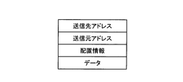
- FIG. 2 is a diagram illustrating a configuration example of an IP address request signal.
- FIG. 3 is a diagram illustrating a configuration example of an IP address distribution signal.
- FIG. 4 is a sequence diagram showing an IP address distribution procedure in the IP address distribution system according to the first embodiment.
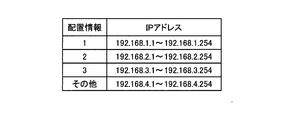
- FIG. 5 is a diagram illustrating an example of an IP address correspondence table.
- FIG. 6 is a diagram illustrating a configuration example of the IP address distribution system according to the second embodiment.
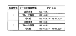
- FIG. 7 is a diagram illustrating an example of an IP address correspondence table.
- FIG. 8 is a diagram illustrating a configuration example of the IP address distribution system according to the third embodiment.
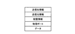
- FIG. 9 is a diagram illustrating a configuration example of an IP address request signal.
- FIG. 10 is a diagram showing an example of the IP address correspondence table.
- FIG. 1 is a diagram illustrating a configuration example of the IP address distribution system according to the first embodiment.
- the IP address distribution system according to the present embodiment includes an IP address distribution device 1 and switches 2 to 4 which are Ethernet (registered trademark) switches.
- the IP address distribution device 1 is connected to the switch 2.
- the switches 3 and 4 are connected to the switch 2.
- devices 5 and 6 are connected to the switch 2, a device 7 is connected to the switch 3, and a device 8 is connected to the switch 4.
- the devices 5 to 8 are devices that request the IP address distribution device 1 to assign an IP address and receive the IP address assignment.
- the IP address distribution device 1 holds an IP address correspondence table 9 and distributes (assigns) an IP address according to the IP address correspondence table 9 when receiving an IP address distribution request.
- each switch holds arrangement information indicating the location where it is installed (position on the physical wiring of the network).
- the switch 2 holds the value 1 as the arrangement information.
- 3 holds a value 2 as arrangement information
- the switch 4 holds a value 3 as arrangement information.
- FIG. 2 is a diagram showing a configuration example of an IP address request signal transmitted to the IP address distribution apparatus 1 when the devices 5 to 8 request IP address distribution in the IP address distribution system of the present embodiment.
- the IP address request signal has areas for storing transmission destination information, transmission source information, arrangement information, and data, respectively.
- the transmission destination information area and the transmission source area information on the destination and transmission source of the IP address request signal is stored, respectively.
- arrangement information area arrangement information held by the switch that relays the IP address request signal first is stored.
- FIG. 3 shows an IP address distribution signal transmitted when the IP address distribution apparatus 1 that has received an IP address request signal distributes an IP address to a request source device in the IP address distribution system of the present embodiment. It is a figure which shows the example of a structure. As shown in the figure, the IP address distribution signal has areas for storing transmission destination information, transmission source information, and data, respectively. In the transmission destination information area and the transmission source area, information on the destination and transmission source of the IP address distribution signal is stored. In the data area, an IP address distributed to the request source device is stored.
- FIG. 4 is a sequence diagram showing an IP address distribution procedure in the IP address distribution system according to the first embodiment.
- each device When each device requests IP address assignment, it transmits an IP address request signal specifying a broadcast address as a transmission destination address to all devices connected to the network.
- As the source information of the IP address request signal device specific information is set.
- the arrangement information area of the IP address request signal is transmitted blank. Note that the data area of the IP address request signal is not used in this embodiment.
- Each switch has a function as a switching hub.
- each switch transfers the signal to a port other than the port that received the signal.
- the arrangement information area of the IP address request signal is confirmed. If arrangement information is not set in this area, the arrangement information held is set and transferred. On the other hand, when arrangement information has already been set in the arrangement information area, it is transferred as it is.
- Each switch repeats such processing, so that the IP address request signal reaches the IP address distribution device 1. In the arrangement information area of the IP address request signal received by the IP address distribution device 1, arrangement information held by the switch to which the requesting device is connected is set.
- the IP address distribution apparatus 1 When receiving the IP address request signal, the IP address distribution apparatus 1 determines an IP address to be distributed and transmits an IP address distribution signal as a signal for notifying the determination result. As the transmission destination information of the IP address distribution signal, the unique information of the request source device (the unique information set in the transmission source information of the received IP address request signal) is set. The details of the IP address distribution (assignment) operation by the IP address distribution apparatus 1 will be described later.
- each switch When each switch receives the IP address distribution signal, each switch performs a transfer process according to the set destination information. As a result, the IP address distribution signal reaches the corresponding device (request source device).
- each device When each device receives an IP address distribution signal addressed to itself, it sets the IP address set in its data area as its own IP address and starts IP communication.
- FIG. 5 is a diagram showing an example of the IP address correspondence table 9 held by the IP address distribution device 1.
- the arrangement information is “1”
- an undistributed IP address from “192.168.1.1 to 192.168.1.254” is selected and distributed.
- the arrangement information is “2”
- an undistributed IP address from “192.168.2.1 to 192.168.2.254” is selected and distributed, and the arrangement information is “3”.
- IP address “192.168.3.1 to 192.168.3.254” an undistributed one is selected and distributed, and the arrangement information is “Other (other than 1, 2, 3)” "Indicates that an undistributed IP address from” 192.168.4.1 to 192.168.4.454 "is selected and distributed.
- IP addresses of “192.168.4.0” and “192.168.4.4255” are used as a network address and a broadcast address, respectively (the address mask is “255.255.255.0”). ), It is excluded from distribution.
- the IP address distribution apparatus 1 determines an IP address to be distributed using the arrangement information added to the IP address request signal and the held IP address correspondence table 9.
- the IP address distribution device 1 sets the transmission source information set in the received IP address request signal as the transmission destination information of the IP address distribution signal, and the transmission source information of the IP address distribution signal.
- the unique information of the IP address distribution device 1 is set in the IP address, and the IP address to be distributed is set in the data area shown in FIG. 3 and transmitted.
- the IP address distribution apparatus 1 selects an undistributed IP address “192.168.1.1 to 192.168.1.254” corresponding to the arrangement information “1” at this time.
- the description will be continued assuming that “192.168.1.1” is selected.
- the IP address distribution device 1 transmits an IP address distribution signal including data of the selected IP address to the device 5.
- the IP address distribution device 1 receives the IP address request signal of the placement information “1”, so that the device 5 is used as the IP address corresponding to the placement information “1”. For example, “192.168.1.2” is selected as a value other than “192.168.1.1” that has already been distributed, and an IP address distribution signal including the data of this IP address is transmitted to the device 6. .
- the IP address distribution device can operate as a DHCP server, and the device can operate as a DHCP client. It is.
- the IP address distribution system includes an IP address distribution device and one or more switches, and each switch holds arrangement information and is connected to its own switch.
- an IP address request signal is received from a device (when an IP address request signal that does not include location information is received)
- the IP address request signal is transferred by adding the location information held therein, and the IP address distribution device
- an undistributed IP address is selected from a range corresponding to the added arrangement information and distributed.
- IP address assigned to the failed device is released at the time of replacement or before replacement, the device after replacement is replaced with the device before replacement.
- the same IP address can be assigned.
- an IP address having a value close to that assigned to the device before replacement is assigned to the device after replacement. be able to.
- the IP address distribution device sends an inquiry to each device to which an IP address has been assigned in a predetermined cycle, and there is no response In this case, the IP address assigned to the corresponding device may be released.
- the IP address distribution device when the IP address distribution device receives the IP address request signal, the IP address distribution device transmits a signal destined for each of the distributed IP addresses in the range corresponding to the added arrangement information, and transmits the device (IP address). If there is a device with no response, the IP address assigned to this device may be redistributed to the device that sent the IP address request signal. In this case, when the device is replaced, the IP address assigned to the device before the replacement can be surely assigned to the device after the replacement.
- FIG. FIG. 6 is a diagram illustrating a configuration example of the IP address distribution system according to the second embodiment.
- the IP address distribution system according to the present embodiment is configured by mounting the IP address distribution device and the switch described in the first embodiment on a train.
- the IP address distribution device 11 and switches 12 to 15 are provided. I have.
- An IP address distribution device 11 and switches 12 and 13 are installed in the first car, and switches 14 and 15 are installed in the second car.
- the IP address distribution device 11 is connected to the switch 12, and the switch 12 and the switch 13 are connected.
- a switch 14 is further connected to the switch 13, and a switch 15 is further connected to the switch 14.
- An air conditioner (AC) 16 is connected to the switch 12, and a brake device (BR) 17 is connected to the switch 13.
- An air conditioner (AC) 18 and a brake device (BR) 19 are connected to the switch 14.
- the air conditioners 16 and 18 and the brake devices 17 and 19 operate as devices that request the IP address distribution described in the first embodiment.
- the IP address distribution device 11 holds an IP address correspondence table (not shown) as in the first embodiment. Moreover, each switch of this Embodiment hold
- the IP address distribution apparatus 11 is installed in the first car is shown, it may be installed in a vehicle other than the first car.
- the number of switches installed in each vehicle is not limited to two. One or three or more may be used depending on the number of devices installed in the vehicle. The number of installed switches may be different for each vehicle.
- the configuration of the IP address request signal transmitted from the air conditioners 16 and 18 and the brake devices 17 and 19 to the IP address distribution device 11 is the same as that of the first embodiment (see FIG. 2).
- the configuration of the IP address distribution signal is the same as that of the first embodiment (see FIG. 3).
- each switch is the same as in the first embodiment. That is, when an IP address request signal for which no arrangement information is set is received, the arrangement information of the switch is set and transferred, and when an IP address request signal for which arrangement information is set is received, it is transferred as it is. To do.
- the IP address distribution device 11 When receiving the IP address request signal, the IP address distribution device 11 determines an IP address to be distributed based on the arrangement information and device information set in this signal and the held IP address correspondence table. . When the IP address is determined, the transmission source information set in the received IP address request signal is set in the transmission destination information, and the unique information of the IP address distribution device 11 is set in the transmission source information of the IP address distribution signal. Then, an IP address distribution signal in which the IP address to be distributed is set in the data area is transmitted. In the following, details of the operation in which the IP address distribution device 11 determines an IP address to be distributed will be described.
- FIG. 7 is a diagram showing an example of an IP address correspondence table held by the IP address distribution device 11.
- the IP address distribution device 11 receives an IP address request signal with the arrangement information “1” and the device information “air conditioner”, the IP address “192. 168.1.1 ”is selected, and when the placement information is“ 1 ”and the device information is“ brake device ”, an IP address request signal is received,“ 192.168.1.2 ”is selected as the IP address,
- an IP address request signal having the arrangement information “1” and the device information “other” (different from both the air conditioner and the brake device) is received, “192.168.1.3 to 192.168.8.1.
- An undistributed IP address from “254” is selected.
- IP address request signal with arrangement information “2” and device information “air conditioner” is received, “192.168.2.1” is selected as the IP address, arrangement information “2” and device information
- IP address request signal having the information “brake device” is received
- 192.168.2.2 is selected as the IP address
- the arrangement information is “2”
- the device information is “other” (air conditioner and brake).
- an undistributed IP address is selected from the IP addresses “192.168.2.3 to 192.168.2.254”.
- the device receiving the IP address distribution is an air conditioner and a brake device has been described, but the device receiving the IP address distribution is not limited to these devices.
- the IP address may be distributed in consideration of only the arrangement information without considering the device type.
- the IP address distribution device can operate as a DHCP server, and the device can operate as a DHCP client. It is.
- the air conditioner or brake device that is a device requesting the IP address distribution transmits an IP address request signal including device information indicating the type of the own device.
- the switch Upon receiving the IP address request signal, the switch adds and transfers its own location information as necessary, and the IP address distribution device adds the device information and location information included in the received IP address request signal. The corresponding IP address was distributed.
- an IP address corresponding to the type can be assigned to a device requesting distribution of an IP address.
- the switch since the switch holds a value that uniquely indicates the installed vehicle as arrangement information, an IP address can be fixedly assigned to each vehicle and each device type. As a result, when the air conditioner or the brake device is replaced, the same IP address as that assigned to the device before replacement can be assigned to the device after replacement.
- FIG. FIG. 8 is a diagram illustrating a configuration example of the IP address distribution system according to the third embodiment.
- the IP address distribution system according to the present embodiment includes an IP address distribution device 21 and switches 22 and 23.
- the IP address distribution device 21 is connected to a physical port (hereinafter simply referred to as a port) P1 of the switch 22. Further, the port P1 of the switch 23 and the port P3 of the switch 22 are connected.
- Devices 24 and 25 are connected to the ports P4 and P5 of the switch 22, respectively, and devices 26 and 27 are connected to the ports P2 and P5 of the switch 23, respectively.
- the IP address distribution device 21 holds an IP address correspondence table 28, and each switch holds the same arrangement information as in the first and second embodiments.
- an IP address is assigned based on the arrangement information of each switch.
- the IP address distribution system of the second embodiment based on the arrangement information of each switch and the type of device.
- the IP address is assigned based on the arrangement information of the switch to which the IP address requesting device is connected and the information on the connection port.
- FIG. 9 is a diagram illustrating a configuration example of an IP address request signal transmitted to the IP address distribution device 21 when the devices 24 to 27 request IP address distribution in the IP address distribution system according to the third embodiment.
- the IP address request signal shown in FIG. 9 is obtained by adding an area for storing physical port information to the IP address request signal (see FIG. 2) of the first embodiment.
- the configuration of the IP address distribution signal transmitted when the IP address distribution apparatus 21 distributes the IP address to the devices 24 to 27 is the same as that of the first embodiment (see FIG. 3).
- each device When each device requests distribution of an IP address, it transmits an IP address request signal having the configuration shown in FIG. At this time, transmission is performed without setting anything in the arrangement information area and the physical port area (leave the blank state).
- a broadcast address is designated as the destination information of the IP address request signal, and unique information of the device that transmits the signal is set as the source information.
- each switch When each switch receives the IP address request signal, it forwards the signal to a port other than the port that received the signal. At this time, the arrangement information area of the IP address request signal is confirmed. If arrangement information is not set in this area, the arrangement information held is set, the physical port area is confirmed, and the physical information is stored in this area. If the port information is not set, the information (port number) of the port that received this signal is set and transferred. On the other hand, when arrangement information is set in the arrangement information area and physical port information is set in the physical port area, the information is transferred as it is.
- the IP address distribution device 21 determines the IP address to be distributed based on the arrangement information and physical port information set in this signal and the held IP address correspondence table 28. decide.
- the IP address is determined, the transmission source information set in the received IP address request signal is set in the transmission destination information, and the unique information of the IP address distribution device 11 is set in the transmission source information of the IP address distribution signal. Then, an IP address distribution signal in which the IP address to be distributed is set in the data area is transmitted.
- the IP address distribution device 21 determines an IP address to be distributed will be described.
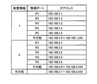
- FIG. 10 is a diagram showing an example of the IP address correspondence table 28 held by the IP address distribution device 21.
- the IP address distribution device 21 assigns the IP address “192.168.k.j” to the device that is the source of the IP address request signal.
- the IP address “192.168.3.1 to 192.168.3.254” Select and assign undistributed ones.
- IP address distribution system of the present embodiment can be applied to a network constructed in a train, as in the second embodiment.
- an IP address is uniquely associated with a combination of arrangement information and physical port information.
- a plurality of IP addresses are allocated to a combination of arrangement information and physical port information, and an IP address is assigned. It is also possible to distribute IP addresses to a plurality of devices using the fact that the address request signal has passed through the physical port of the switch as a criterion. That is, for example, when another switch (ordinary switch that does not hold arrangement information) is connected to a physical port with a switch, and a plurality of devices are connected via this switch, It is also possible to distribute a series of related IP addresses to devices.
- the switch when the switch receives the IP address request signal, it adds the location information of itself and the information of the physical port that has received the IP address request signal as necessary. Then, the IP address distribution device distributes the IP address according to the device information and the physical port information added to the received IP address request signal. As a result, the IP address can be distributed to the request source device of the IP address in correspondence with the installation position of the request source device and the physical port of the connected switch. As a result, for example, when the device is replaced, the same IP address as that assigned to the device before replacement can be assigned to the device after replacement.
- the IP address distribution system according to the present invention is useful when it is necessary to manage and assign IP addresses in consideration of the physical configuration of the network.
- IP address distribution device 1,11,21 IP address distribution device 2,3,4,12,13,14,15,22,23 Switch 5, 6, 7, 8, 24, 25, 26, 27 Equipment 9, 28 IP address correspondence table 16, 18 Air conditioner (AC) 17, 19 Brake device (BR)
Landscapes
- Engineering & Computer Science (AREA)
- Computer Networks & Wireless Communication (AREA)
- Signal Processing (AREA)
- Small-Scale Networks (AREA)
- Data Exchanges In Wide-Area Networks (AREA)
Abstract
Description
図1は、実施の形態1のIPアドレス配布システムの構成例を示す図である。本実施の形態のIPアドレス配布システムは、IPアドレス配布装置1と、イーサネット(登録商標)スイッチであるスイッチ(Switch)2~4とを含んで構成されている。IPアドレス配布装置1は、スイッチ2に接続されている。また、スイッチ3および4はスイッチ2に接続されている。また、スイッチ2には機器5および6が接続され、スイッチ3には機器7が接続され、スイッチ4には機器8が接続されている。なお、機器5~8はIPアドレス配布装置1に対してIPアドレスを割り当てるように要求し、IPアドレスの割り当てを受ける装置である。IPアドレス配布装置1は、IPアドレス対応表9を保持しており、IPアドレスの配布要求を受けた場合には、IPアドレス対応表9に従ってIPアドレスを配布する(割り当てる)。
図6は、実施の形態2のIPアドレス配布システムの構成例を示す図である。本実施の形態のIPアドレス配布システムは、実施の形態1で説明したIPアドレス配布装置およびスイッチを列車に搭載して構成したものであり、IPアドレス配布装置11と、スイッチ12~15と、を備えている。IPアドレス配布装置11と、スイッチ12および13とが1号車に設置され、スイッチ14および15が2号車に設置されている。IPアドレス配布装置11はスイッチ12に接続され、スイッチ12とスイッチ13が接続されている。スイッチ13には、さらにスイッチ14が接続され、スイッチ14には、さらにスイッチ15が接続されている。また、スイッチ12には、空調装置(AC)16が接続され、スイッチ13には、ブレーキ装置(BR)17が接続されている。スイッチ14には、空調装置(AC)18およびブレーキ装置(BR)19が接続されている。空調装置16,18およびブレーキ装置17,19は、実施の形態1で説明したIPアドレスの配布を要求する機器として動作する。
図8は、実施の形態3のIPアドレス配布システムの構成例を示す図である。本実施の形態のIPアドレス配布システムは、IPアドレス配布装置21と、スイッチ22および23とを含んで構成されている。IPアドレス配布装置21は、スイッチ22の物理ポート(以下、単にポートと呼ぶ)P1に接続されている。また、スイッチ23のポートP1とスイッチ22のポートP3が接続されている。スイッチ22のポートP4およびP5には機器24および25がそれぞれ接続され、スイッチ23のポートP2およびP5には機器26および27がそれぞれ接続されている。IPアドレス配布装置21は、IPアドレス対応表28を保持し、各スイッチは、実施の形態1,2と同様の配置情報を保持している。先の実施の形態1のIPアドレス配布システムでは各スイッチの配置情報に基づいてIPアドレスを割り当てることとし、また、実施の形態2のIPアドレス配布システムでは各スイッチの配置情報および機器の種別に基づいてIPアドレスを割り当てることとしたが、本実施の形態のIPアドレス配布システムでは、IPアドレス要求元の機器が接続されているスイッチの配置情報と接続ポートの情報とに基づいてIPアドレスを割り当てる。
2,3,4,12,13,14,15,22,23 スイッチ(Switch)
5,6,7,8,24,25,26,27 機器
9,28 IPアドレス対応表
16,18 空調装置(AC)
17,19 ブレーキ装置(BR)
Claims (13)
- 複数のスイッチ装置により形成されたネットワーク、および当該ネットワークに接続されたIPアドレス配布装置を備え、
前記スイッチ装置は、ネットワーク内における自身の位置を示す配置情報を保持しており、自身に接続された機器からIPアドレス要求信号を受信した場合、保持している配置情報を付加して転送し、
前記IPアドレス配布装置は、IPアドレス要求信号を受信した場合、当該信号に付加されている配置情報に応じた範囲からIPアドレスを選択して要求元の機器に配布することを特徴とするIPアドレス配布システム。 - 前記IPアドレス配布装置は、前記配置情報への設定値ごとに異なる範囲のIPアドレスを配布することを特徴とする請求項1に記載のIPアドレス配布システム。
- 前記機器は、IPアドレスの割り当てを要求する場合、IPアドレス要求信号に自身の機器種別を示す情報を付加して送信し、
前記IPアドレス配布装置は、IPアドレス要求信号を受信した場合、当該信号に付加されている配置情報および機器種別を示す情報に応じた範囲からIPアドレスを選択して要求元の機器に配布することを特徴とする請求項1に記載のIPアドレス配布システム。 - 前記IPアドレス配布装置は、前記配置情報への設定値と前記機器種別の組み合わせごとに異なる範囲のIPアドレスを配布することを特徴とする請求項3に記載のIPアドレス配布システム。
- 前記スイッチ装置は、自身に接続された機器からIPアドレス要求信号を受信した場合、前記配置情報および当該IPアドレス要求信号を受信した物理ポートの情報を付加して転送し、
前記IPアドレス配布装置は、IPアドレス要求信号を受信した場合、当該信号に付加されている配置情報および物理ポートの情報に応じた範囲からIPアドレスを選択して要求元の機器に配布することを特徴とする請求項1に記載のIPアドレス配布システム。 - 前記IPアドレス配布装置は、前記配置情報への設定値と前記物理ポートの組み合わせごとに異なる範囲のIPアドレスを配布することを特徴とする請求項5に記載のIPアドレス配布システム。
- 前記ネットワークを列車内に構築されたネットワークとすることを特徴とする請求項1に記載のIPアドレス配布システム。
- 前記スイッチ装置は、自身が設置されている車両の列車編成内における位置の情報を前記配置情報として保持していることを特徴とする請求項7に記載のIPアドレス配布システム。
- 複数のスイッチ装置により形成されたネットワーク、および当該ネットワークに接続されたIPアドレス配布装置を備え、前記スイッチ装置はネットワーク内における自身の位置を示す配置情報を保持している構成のシステムにおけるIPアドレス配信方法であって、
前記スイッチ装置が、自身に接続された機器からIPアドレス要求信号を受信した場合に、保持している配置情報を当該受信したIPアドレス要求信号に付加して転送する転送ステップと、
前記IPアドレス配布装置が、前記スイッチ装置により転送されたIPアドレス要求信号を受信した場合に、受信したIPアドレス要求信号に付加されている配置情報に応じた範囲からIPアドレスを選択して要求元の機器に配布するIPアドレス配布ステップと、
を含むことを特徴とするIPアドレス配布方法。 - 前記機器が、IPアドレス要求信号に自身の機器種別を示す情報を付加して送信する要求信号送信ステップ、
をさらに含み、
前記IPアドレス配布ステップでは、IPアドレス要求信号に付加されている配置情報および機器種別を示す情報に応じた範囲からIPアドレスを選択して要求元の機器に配布することを特徴とする請求項9に記載のIPアドレス配布方法。 - 前記転送ステップでは、前記配置情報に加え、さらに、前記IPアドレス要求信号を受信した物理ポートの情報をIPアドレス要求信号に付加して転送し、
前記IPアドレス配布ステップでは、IPアドレス要求信号に付加されている配置情報および物理ポートの情報に応じた範囲からIPアドレスを選択して要求元の機器に配布することを特徴とする請求項9に記載のIPアドレス配布方法。 - 前記ネットワークを列車内に構築されたネットワークとすることを特徴とする請求項9に記載のIPアドレス配布方法。
- 前記スイッチ装置は、自身が設置されている車両の列車編成内における位置の情報を前記配置情報として保持していることを特徴とする請求項12に記載のIPアドレス配布方法。
Priority Applications (5)
| Application Number | Priority Date | Filing Date | Title |
|---|---|---|---|
| EP11872932.6A EP2763351A4 (en) | 2011-09-26 | 2011-09-26 | IP ADDRESS DISTRIBUTION SYSTEM AND IP ADDRESS DISTRIBUTION METHOD |
| US14/346,567 US9306901B2 (en) | 2011-09-26 | 2011-09-26 | IP address distribution system and IP address distribution method |
| PCT/JP2011/071917 WO2013046304A1 (ja) | 2011-09-26 | 2011-09-26 | Ipアドレス配布システムおよびipアドレス配布方法 |
| JP2012502338A JP5031125B1 (ja) | 2011-09-26 | 2011-09-26 | Ipアドレス配布システムおよびipアドレス配布方法 |
| CN201180073658.XA CN103828333B (zh) | 2011-09-26 | 2011-09-26 | Ip地址分配系统及ip地址分配方法 |
Applications Claiming Priority (1)
| Application Number | Priority Date | Filing Date | Title |
|---|---|---|---|
| PCT/JP2011/071917 WO2013046304A1 (ja) | 2011-09-26 | 2011-09-26 | Ipアドレス配布システムおよびipアドレス配布方法 |
Publications (1)
| Publication Number | Publication Date |
|---|---|
| WO2013046304A1 true WO2013046304A1 (ja) | 2013-04-04 |
Family
ID=47016600
Family Applications (1)
| Application Number | Title | Priority Date | Filing Date |
|---|---|---|---|
| PCT/JP2011/071917 Ceased WO2013046304A1 (ja) | 2011-09-26 | 2011-09-26 | Ipアドレス配布システムおよびipアドレス配布方法 |
Country Status (5)
| Country | Link |
|---|---|
| US (1) | US9306901B2 (ja) |
| EP (1) | EP2763351A4 (ja) |
| JP (1) | JP5031125B1 (ja) |
| CN (1) | CN103828333B (ja) |
| WO (1) | WO2013046304A1 (ja) |
Cited By (2)
| Publication number | Priority date | Publication date | Assignee | Title |
|---|---|---|---|---|
| WO2016079824A1 (ja) * | 2014-11-19 | 2016-05-26 | 三菱電機株式会社 | Ipアドレス配信装置、ipアドレス配信システム、およびipアドレス配信方法 |
| JP2023539383A (ja) * | 2020-09-15 | 2023-09-13 | 中車株洲電力機車研究所有限公司 | イーサネット列車ネットワーク制御システム及びその自動配置方法、鉄道車両 |
Families Citing this family (11)
| Publication number | Priority date | Publication date | Assignee | Title |
|---|---|---|---|---|
| JP3216268B2 (ja) | 1991-10-30 | 2001-10-09 | 住友化学工業株式会社 | エポキシドの製法 |
| WO2014142258A1 (ja) * | 2013-03-14 | 2014-09-18 | 日本電気株式会社 | 通信システム、制御装置、アドレス割当方法及びプログラム |
| CN106576059B (zh) | 2014-07-18 | 2019-10-11 | 三菱电机株式会社 | Ip地址分发系统、交换机装置以及ip地址分发方法 |
| CN104702717B (zh) * | 2015-04-03 | 2018-01-12 | 上海自仪泰雷兹交通自动化系统有限公司 | Cbtc中数据通信系统用ip地址的规划方法 |
| CN107531158B (zh) * | 2015-04-20 | 2020-04-28 | 三菱电机株式会社 | 列车数据传输系统及列车数据传输程序 |
| US10200342B2 (en) * | 2015-07-31 | 2019-02-05 | Nicira, Inc. | Dynamic configurations based on the dynamic host configuration protocol |
| CN106210169A (zh) * | 2016-07-13 | 2016-12-07 | 邦彦技术股份有限公司 | Ip地址自动分配方法及装置 |
| CN107005603A (zh) * | 2016-08-30 | 2017-08-01 | 深圳前海达闼云端智能科技有限公司 | 用于ip地址分配的方法、装置、系统和计算机程序产品 |
| JP2019149723A (ja) * | 2018-02-27 | 2019-09-05 | オムロン株式会社 | 通信装置、通信装置の制御方法 |
| CN112040026A (zh) * | 2020-09-10 | 2020-12-04 | 株洲中车时代电气股份有限公司 | 基于列车以太网的智能地址分配管理装置、系统及方法 |
| CN112217914B (zh) * | 2020-09-24 | 2023-02-24 | 交控科技股份有限公司 | 基于城市轨道交通线网级云平台的ip分配方法及装置 |
Citations (3)
| Publication number | Priority date | Publication date | Assignee | Title |
|---|---|---|---|---|
| JP2006237790A (ja) * | 2005-02-23 | 2006-09-07 | Seiko Epson Corp | Ipアドレス割当装置およびipアドレス割当方法並びにipアドレス割当プログラムと記録媒体 |
| WO2010087258A1 (ja) * | 2009-01-27 | 2010-08-05 | 三菱電機株式会社 | 列車用通信システム及び列車用通信方法 |
| WO2011074123A1 (ja) * | 2009-12-18 | 2011-06-23 | 三菱電機株式会社 | Ipアドレス配信システムおよびipアドレス配信方法 |
Family Cites Families (6)
| Publication number | Priority date | Publication date | Assignee | Title |
|---|---|---|---|---|
| JP4023240B2 (ja) * | 2002-07-10 | 2007-12-19 | 日本電気株式会社 | ユーザ認証システム |
| DE10315730A1 (de) * | 2003-04-04 | 2004-11-04 | Abb Patent Gmbh | Schaltanlagensystem und Verfahren zur Installation von Einschubgeräten in Schaltanlagen |
| WO2007133788A2 (en) * | 2006-05-12 | 2007-11-22 | Telsima Corporation | Dynamic vlans in wireless networks |
| US8755307B2 (en) * | 2009-01-28 | 2014-06-17 | Mitsubishi Electric Corporation | IP-address distribution device and IP-address distribution method |
| JP2011135453A (ja) * | 2009-12-25 | 2011-07-07 | Sogo Keibi Hosho Co Ltd | 制御装置、制御方法及び制御プログラム |
| US8868700B2 (en) * | 2010-12-28 | 2014-10-21 | Nant Holdings Ip, Llc | Distributed network interfaces for application cloaking and spoofing |
-
2011
- 2011-09-26 EP EP11872932.6A patent/EP2763351A4/en not_active Withdrawn
- 2011-09-26 US US14/346,567 patent/US9306901B2/en active Active
- 2011-09-26 JP JP2012502338A patent/JP5031125B1/ja active Active
- 2011-09-26 CN CN201180073658.XA patent/CN103828333B/zh active Active
- 2011-09-26 WO PCT/JP2011/071917 patent/WO2013046304A1/ja not_active Ceased
Patent Citations (3)
| Publication number | Priority date | Publication date | Assignee | Title |
|---|---|---|---|---|
| JP2006237790A (ja) * | 2005-02-23 | 2006-09-07 | Seiko Epson Corp | Ipアドレス割当装置およびipアドレス割当方法並びにipアドレス割当プログラムと記録媒体 |
| WO2010087258A1 (ja) * | 2009-01-27 | 2010-08-05 | 三菱電機株式会社 | 列車用通信システム及び列車用通信方法 |
| WO2011074123A1 (ja) * | 2009-12-18 | 2011-06-23 | 三菱電機株式会社 | Ipアドレス配信システムおよびipアドレス配信方法 |
Non-Patent Citations (2)
| Title |
|---|
| DOUGLAS E. COMER: "TCP/IP", vol. 1, KYORITSU SHUPPAN |
| See also references of EP2763351A4 |
Cited By (4)
| Publication number | Priority date | Publication date | Assignee | Title |
|---|---|---|---|---|
| WO2016079824A1 (ja) * | 2014-11-19 | 2016-05-26 | 三菱電機株式会社 | Ipアドレス配信装置、ipアドレス配信システム、およびipアドレス配信方法 |
| JPWO2016079824A1 (ja) * | 2014-11-19 | 2017-04-27 | 三菱電機株式会社 | Ipアドレス配信装置、ipアドレス配信システム、およびipアドレス配信方法 |
| JP2023539383A (ja) * | 2020-09-15 | 2023-09-13 | 中車株洲電力機車研究所有限公司 | イーサネット列車ネットワーク制御システム及びその自動配置方法、鉄道車両 |
| JP7625689B2 (ja) | 2020-09-15 | 2025-02-03 | 中車株洲電力機車研究所有限公司 | イーサネット列車ネットワーク制御システム及びその自動配置方法、鉄道車両 |
Also Published As
| Publication number | Publication date |
|---|---|
| CN103828333B (zh) | 2017-08-25 |
| US20140222982A1 (en) | 2014-08-07 |
| CN103828333A (zh) | 2014-05-28 |
| JPWO2013046304A1 (ja) | 2015-03-26 |
| EP2763351A4 (en) | 2015-02-18 |
| EP2763351A1 (en) | 2014-08-06 |
| US9306901B2 (en) | 2016-04-05 |
| JP5031125B1 (ja) | 2012-09-19 |
Similar Documents
| Publication | Publication Date | Title |
|---|---|---|
| JP5031125B1 (ja) | Ipアドレス配布システムおよびipアドレス配布方法 | |
| JP5106707B1 (ja) | Ipアドレス配布システムおよびipアドレス配布方法 | |
| JP5312610B2 (ja) | Ipアドレス配信システムおよびipアドレス配信方法 | |
| JP4896278B1 (ja) | Ipアドレス配布システム | |
| JP5490329B2 (ja) | 列車用通信システム | |
| CN102301653B (zh) | Ip地址分发装置以及ip地址分发方法 | |
| JPWO2010087258A1 (ja) | 列車用通信システム及び列車用通信方法 | |
| CN104618156A (zh) | 网络配置的方法及装置 | |
| JP5936780B2 (ja) | Ipアドレス配布システム、スイッチ装置およびipアドレス配布方法 | |
| JP5677244B2 (ja) | 列車情報管理装置 | |
| JP6192838B2 (ja) | Ipアドレス配布システム、スイッチ装置、およびipアドレス配布方法 | |
| KR101068207B1 (ko) | Dhcp 이중화 시스템 및 방법 |
Legal Events
| Date | Code | Title | Description |
|---|---|---|---|
| ENP | Entry into the national phase |
Ref document number: 2012502338 Country of ref document: JP Kind code of ref document: A |
|
| 121 | Ep: the epo has been informed by wipo that ep was designated in this application |
Ref document number: 11872932 Country of ref document: EP Kind code of ref document: A1 |
|
| WWE | Wipo information: entry into national phase |
Ref document number: 14346567 Country of ref document: US Ref document number: 2011872932 Country of ref document: EP |
|
| NENP | Non-entry into the national phase |
Ref country code: DE |