WO2013046447A1 - リレーノード、無線通信システム、および無線通信方法 - Google Patents
リレーノード、無線通信システム、および無線通信方法 Download PDFInfo
- Publication number
- WO2013046447A1 WO2013046447A1 PCT/JP2011/072600 JP2011072600W WO2013046447A1 WO 2013046447 A1 WO2013046447 A1 WO 2013046447A1 JP 2011072600 W JP2011072600 W JP 2011072600W WO 2013046447 A1 WO2013046447 A1 WO 2013046447A1
- Authority
- WO
- WIPO (PCT)
- Prior art keywords
- base station
- radio base
- handover
- relay node
- station
- Prior art date
- Legal status (The legal status is an assumption and is not a legal conclusion. Google has not performed a legal analysis and makes no representation as to the accuracy of the status listed.)
- Ceased
Links
Images


Classifications
-
- H—ELECTRICITY
- H04—ELECTRIC COMMUNICATION TECHNIQUE
- H04B—TRANSMISSION
- H04B7/00—Radio transmission systems, i.e. using radiation field
- H04B7/14—Relay systems
- H04B7/15—Active relay systems
-
- H—ELECTRICITY
- H04—ELECTRIC COMMUNICATION TECHNIQUE
- H04B—TRANSMISSION
- H04B7/00—Radio transmission systems, i.e. using radiation field
- H04B7/14—Relay systems
- H04B7/15—Active relay systems
- H04B7/155—Ground-based stations
- H04B7/15557—Selecting relay station operation mode, e.g. between amplify and forward mode, decode and forward mode or FDD - and TDD mode
-
- H—ELECTRICITY
- H04—ELECTRIC COMMUNICATION TECHNIQUE
- H04W—WIRELESS COMMUNICATION NETWORKS
- H04W36/00—Hand-off or reselection arrangements
- H04W36/0005—Control or signalling for completing the hand-off
- H04W36/0055—Transmission or use of information for re-establishing the radio link
- H04W36/0058—Transmission of hand-off measurement information, e.g. measurement reports
-
- H—ELECTRICITY
- H04—ELECTRIC COMMUNICATION TECHNIQUE
- H04W—WIRELESS COMMUNICATION NETWORKS
- H04W36/00—Hand-off or reselection arrangements
- H04W36/24—Reselection being triggered by specific parameters
- H04W36/30—Reselection being triggered by specific parameters by measured or perceived connection quality data
- H04W36/302—Reselection being triggered by specific parameters by measured or perceived connection quality data due to low signal strength
-
- H—ELECTRICITY
- H04—ELECTRIC COMMUNICATION TECHNIQUE
- H04W—WIRELESS COMMUNICATION NETWORKS
- H04W84/00—Network topologies
- H04W84/02—Hierarchically pre-organised networks, e.g. paging networks, cellular networks, WLAN [Wireless Local Area Network] or WLL [Wireless Local Loop]
- H04W84/04—Large scale networks; Deep hierarchical networks
- H04W84/042—Public Land Mobile systems, e.g. cellular systems
- H04W84/047—Public Land Mobile systems, e.g. cellular systems using dedicated repeater stations
Definitions
- the present invention relates to a relay node that relays communication between a mobile station and a first radio base station, and hands over the communicating mobile station from the first radio base station to the second radio base station together with the mobile station. And a wireless communication method.
- LTE Long Term Evolution
- 3GPP 3rd Generation Generation Partnership Project
- relay Node a relay node that relays communication between a mobile station (User Equipment, UE) and a radio base station (evolved NodeB, eNodeB) is being studied.
- the radio base station eNodeB connected to the relay node RN is referred to as Donor eNodeB (DeNB).
- the relay node RN has a function similar to that of the radio base station eNodeB.
- the functions of the radio base station eNodeB provided in the relay node RN include terminating Evolved Universal Terrestrial Radio Access (E-UTRA) radio interface, S1 interface, and X2 interface radio protocols.
- the relay node RN may have a function defined by a radio base station eNodeB such as a radio network layer (Radio Network Layer, RNL) and a transport network layer (Transport Network Layer, TNL).
- a radio base station eNodeB such as a radio network layer (Radio Network Layer, RNL) and a transport network layer (Transport Network Layer, TNL).
- the relay node RN has a part of the function of the mobile station UE in addition to the function of the radio base station eNodeB.
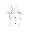
- the relay node RNs1 includes each function illustrated in FIG. 1 in order to wirelessly connect to the radio base station DeNBs2 and the mobility management device MMEs3. That is, the relay node RNs1 includes a physical layer (PYS) f1, a media access control (Medium Access Control, MAC) f2, a radio link control (Radio Link Control, RLC) f4, a Packet Data Convergence Protocol (PDCP) f3, a radio resource Control (Radio Resource Control, RRC) f5 and Non-Access Stratum (NAS) f6.
- PYS physical layer
- MAC Media Access Control
- RLC Radio Link Control
- PDCP Packet Data Convergence Protocol
- RRC Radio Resource Control
- NAS Non-Access Stratum
- an E-UTRAN radio access bearer (E-RAB) is set between the mobile station UE and a core network node (core node, CN) called Evolved packet core (EPC). Is done. Further, a Uu bearer is set between the mobile station UE and the relay node RN, a Un bearer is set between the relay node RN and the radio base station DeNB, and between the radio base station DeNB and the core node CN. S1 bearer is set.
- the relay node RN can be used to expand the communication area (coverage) or increase the traffic capacity. Various scenarios are assumed in which such relay nodes are installed.
- a relay node RN is mounted on a moving vehicle in order to provide a communication area for a mobile station UE possessed by a passenger in the moving vehicle such as a bus or a train. Accordingly, there is a scenario for connecting to the optimal radio base station DeNB.
- the relay node RN is required to have a handover control procedure in order to connect to the optimal radio base station DeNB as the moving vehicle moves.
- the radio relay station connected to the radio base station switches the connection destination to another radio base station or is connected to the radio relay station.
- an existing terminal is handed over to another radio base station.
- a mobile base station is mounted on a vehicle set so that wireless communication between the inside and outside of the vehicle is cut off, and the mobile phone in the vehicle communicates with a fixed base station outside the vehicle only through the mobile base station.
- a conventional technology to set to There is a conventional technology to set to.
- the first radio base station when the relay node is handed over from the first radio base station to the second radio base station, the first radio base station notifies the relay node of a predetermined timing.
- the second radio base station schedules the downlink signal to be transmitted to the relay node at the predetermined timing.
- the relay node schedules the downlink signal to be transmitted at a timing other than the predetermined timing.
- JP 2011-61453 A WO2006 / 126261 JP 2011-4374 A
- 3GPP TS36.300 “Evolved Universal Terrestrial Radio Access (E-UTRA) and Evolved Universal Terrestrial Radio Access Network (E-UTRAN); Overall Description; Stage 2 (Release 10), June 24, 2011 3GPP TS36.423, “Technical Specification Group Radio Access Network; Evolved Universal Terrestrial Radio Access Network (E-UTRAN); X2 Application Protocol (X2AP) (Release 10), June 24, 2011 3GPP TS 23.401, “Technical Specification Group Radio Access Network; Evolved Universal Terrestrial Radio Access Network (E-UTRAN) X2 Application Protocol (X2AP) (Release 10), June 12, 2011
- the relay node RN is required to have a handover control procedure in order to connect to the optimal radio base station DeNB as the moving vehicle moves. .
- the relay node RN mounted on the moving vehicle and the mobile station UE in the moving vehicle move with the movement of the moving vehicle. Therefore, the relay node RN changes from the currently connected first radio base station Source-DeNB (S-DeNB) to the target second radio base station Target-DeNB (T-DeNB) that is newly determined to be optimal. It is necessary to perform handover with the mobile station UE in communication.
- S-DeNB Source-DeNB
- T-DeNB Target-DeNB
- the specific handover control procedure in the above scenario is not standardized in 3GPP. Therefore, it is considered that the handover control procedure standardized in 3GPP for the case where the mobile station UE performs handover from the first radio base station S-DeNB to the second radio base station T-DeNB is applied to the handover control procedure in the above scenario. It is done.
- the first radio base station S-DeNB to the second radio base station User data is transferred to the T-DeNB. That is, there is transfer of user data for transferring a packet that has not been transmitted from the first radio base station S-DeNB to the mobile station UE from the first radio base station S-DeNB to the second radio base station T-DeNB. Done.
- the second radio base station T-DeNB can transmit the packet transferred from the first radio base station S-DeNB to the mobile station UE when the handover is completed. Packet loss associated with the can be prevented.
- FIG. 2 is an explanatory diagram of a first case where a handover control procedure standardized by 3GPP is applied.
- the mobile station UE1 exists in the communication area of the relay node RN2, and is connected to the relay node RN2.
- the relay node RN2 exists in the communication area of the first radio base station S-DeNB 3s and is connected to the first radio base station S-DeNB 3s.
- the first radio base station S-DeNB 3s is connected to a mobility management device (Mobility Management Entity, MME) 4 and a gateway (Gateway, GW) 5, respectively.
- MME Mobility Management Entity
- GW Gateway
- the second radio base station T-DeNB 3t is connected to the mobility management device MME4 and the gateway GW5, respectively.
- the user data of the mobile station UE1 under the relay node RN2 is transferred to the relay node RN2 via the gateway GW5 and the first radio base station S-DeNB 3s.
- the user data transferred from the gateway GW5 to the relay node RN2 via the first radio base station S-DeNB3s is returned from the relay node RN2 to the first radio base station S-DeNB3s.
- the first radio base station S-DeNB 3s transfers the user data returned from the relay node RN2 to the second radio base station T-DeNB 3t.
- the second radio base station T-DeNB 3t transfers the user data transferred from the first radio base station S-DeNB 3s to the mobile station UE1 that has moved into the communication area of the second radio base station T-DeNB 3t. Send.
- FIG. 3 is an explanatory diagram of a second case where a handover control procedure standardized by 3GPP is applied.
- the relay node RN2 stays in the communication area of the first radio base station S-DeNB3s, the mobile station UE1 moves from the communication area of the relay node RN2 to the communication area of the second radio base station T-DeNB3t, This is a case where a handover has occurred in the mobile station UE1.
- the mobile station UE1 together with the relay node RN2 moves from the communication area of the first radio base station S-DeNB3s to the communication area of the second radio base station T-DeNB3t. This is a case where handover has occurred.
- the user data transferred from the gateway GW5 to the relay node RN2 via the first radio base station S-DeNB3s is returned from the relay node RN2 to the first radio base station S-DeNB3s.
- the first radio base station S-DeNB 3s transfers the user data returned from the relay node RN2 to the second radio base station T-DeNB 3t.
- the second radio base station T-DeNB 3t transfers the user data transferred from the first radio base station S-DeNB 3s again to the relay node RN2 that has moved to the communication area of the second radio base station T-DeNB 3t.
- forwarding of user data is performed in order to prevent packet loss due to handover. Therefore, it is unnecessary processing to transfer user data between the same relay nodes RN2 as in the path p2 of FIG. In addition, it is not an efficient use of a wireless line to transfer user data between the same relay nodes.
- An object of the present invention is to perform handover control for efficiently executing user data forwarding (forwarding) when a relay node and a mobile station under the relay node move together to cause a handover to the relay node and the mobile station. Is to provide a procedure.
- the relay node that is registered in the first radio base station and the first mobility management device and relays communication between the mobile station and the first radio base station includes the relay node, the first radio base station, and A handover control signal for the mobile station is determined when handover of the relay node is performed and handover of the mobile station from the first radio base station to the second radio base station is determined. Is transmitted to the second radio base station or the first mobility management device.
- a relay node registered in the first radio base station and the first mobility management device and relaying communication between the mobile station and the first radio base station, and the mobile station are the first radio base station.
- the handover process for the relay node is performed.
- the mobile station is determined to be handed over from the first radio base station to the second radio base station, and a handover control signal for the mobile station is transmitted to the second radio base station or the first mobility management device.
- FIG. 6 is a sequence diagram of handover control according to an embodiment of an X2 handover case.
- FIG. 6 is a sequence diagram of handover control according to an embodiment of an S1 handover case.
- FIG. 10 is a flowchart of a handover process of a relay node RN when a “radio environment measurement report” message is received from a mobile station UE.
- It is a hardware block diagram of the mobile station UE according to embodiment.
- It is a hardware block diagram of relay node RN according to an embodiment.
- It is a functional block diagram of the control apparatus of the relay node RN according to the embodiment.
- It is an example of the information table stored for every mobile station UE in the communicating mobile station information storage part.
- FIG. 6 is a configuration example of another “handover request” message according to the embodiment.
- FIG. 6 is a configuration example of a “handover completion (radio resource control connection reconfiguration completion)” message according to the embodiment. It is a hardware block diagram of the radio base station DeNB according to embodiment. It is a functional block diagram of the control apparatus of the radio base station DeNB according to embodiment. 6 is a configuration example of a “handover request confirmation” message according to the embodiment. It is a structural example of another "handover request confirmation” message according to the embodiment.
- FIG. 10 is an operation flowchart of the relay node RN from reception of a “radio resource control connection request” message to transmission of a “handover request message”.
- FIG. 10 is an operation flowchart of the radio base station DeNB from reception of a “handover request” message to transmission of a “handover request confirmation” message.
- FIG. 10 is an operation flow diagram of the relay node RN from reception of a “handover request confirmation” message to transmission of a “handover completion” message.
- FIG. 10 is an operation flowchart of the radio base station DeNB from the reception of a “handover completion” message to the completion of path switching.
- FIG. 4 is a configuration example of a wireless communication system according to the embodiment.
- the radio communication system shown in FIG. 4 includes a mobile station UE10-1, a relay node RN20, a first radio base station S-DeNB30s, a second radio base station T-DeNB30t, a first mobility management device MME40, and a gateway GW50. It is.
- the mobile station UE10-1 exists in the communication area of the relay node RN20 and is connected to the relay node RN20.
- the relay node RN20 is connected to one mobile station UE10-1 existing in the communication area.
- the relay node RN20 can be connected to a plurality of mobile stations UE10-1 to 10-n (n is an arbitrary integer) in the communication area.
- the relay node RN20 exists in the communication area of the first radio base station S-DeNB 30s and is connected to the first radio base station S-DeNB 30s.
- the first radio base station S-DeNB 30s is connected to the first mobility management device MME 40 and the gateway GW 50, respectively.
- the second radio base station T-DeNB 30t is connected to the first mobility management device MME 40 and the gateway GW 50, respectively.
- the first mobility management device MME 40 and the gateway GW 50 are nodes included in a core network called EPC.
- the first radio base station S-DeNB 30s and the second radio base station T-DeNB 30t are connected to the same first mobility management device MME40.
- the second radio base station T-DeNB 30t is connected to a second mobility management device MME different from the first radio base station S-DeNB 30s. May be.
- user data related to the mobile stations UE10-1 to 10-n subordinate to the relay node RN20 passes through the gateway GW50 and the radio base station S-DeNB30s as shown in the path p11. It is transferred to relay node RN20.
- the relay node RN20, the first radio base station S-DeNB 30s, the second radio base station T-DeNB 30t, and the first mobility management device MME 40 execute the following processes (1) to (6) .
- the relay node RN20 manages all the mobile stations UE10-1 to 10-n that are in communication within the communication area.
- the relay node RN20 captures the instance information and context information of each of the mobile stations UE10-1 to 10-n in the process of RRC connection and E-RAB setup performed at the start of communication of each of the mobile stations UE10-1 to 10-n. To do.
- the relay node RN20 stores the supplemented instance information and context information for each mobile station UE. That is, the relay node RN20 stores the context information of each of the mobile stations UE10-1 to 10-n in association with the instance information of each of the mobile stations UE10-1 to 10-n.
- the relay node RN20 releases the instance information and context information of the target mobile stations UE10-1 to 10-n.
- the E-RAB is a mobile station UE10-1 from a subordinate of the relay node RN20 to another subordinate relay node RN or subordinate of the radio base station T-DeNB from an end-of-call, a radio link failure (RadioRadLink Failure, RLF), etc. Released by movement of ⁇ 10-n.
- the relay node RN20 detects radio quality degradation with the first radio base station S-DeNB 30s due to movement of the local station RN20.
- the relay node RN20 uses the same function as that of the mobile station UE included in the local station RN20 to detect the radio quality deterioration in the local station RN20 in the above (2). Perform X2-based handover processing.
- the relay node RN20 does not trigger the reception of the “radio environment measurement report” message from the mobile stations UE10-1 to 10-n, but based on the detection of the radio quality deterioration in the local station RN20 in the above (2). Then, the handover process for the mobile stations UE10-1 to 10-n is started.
- the relay node RN20 based on information (instance information and context information acquired in the process (1) above) of all mobile stations UE10-1 to 10-n in communication, the mobile stations UE10-1 to 10-10 Generate a handover control signal for -n. Then, the relay node RN20 notifies the generated handover control signal to the second radio base station T-DeNB 30t.
- the autonomous notification of the handover control signal to all the mobile stations UE10-1 to 10-n in communication may be performed for each mobile station UE. Further, the handover control signals for all the mobile stations UE10-1 to 10-n may be bundled into one.
- the second radio base station T-DeNB 30t is connected to a second mobility management device MME different from the first radio base station S-DeNB 30s, and the first radio base station S -Assume that the X2 interface is not established between the DeNB 30s and the second radio base station T-DeNB 30t.
- This case is hereinafter referred to as the S1 handover case for convenience.
- the relay node RN20 uses the same function as that of the mobile station UE included in the local station RN20, and detects the radio quality deterioration in the local station RN20 in the above (2). S1-based handover processing is performed.
- the relay node RN20 does not trigger the reception of the “radio environment measurement report” message from the mobile stations UE10-1 to 10-n, but based on the detection of the radio quality deterioration in the local station RN20 in the above (2). Then, the handover process for the mobile stations UE10-1 to 10-n is started.
- the relay node RN20 generates a handover control signal based on the information (instance information and context information acquired in the process (1) above) of all the mobile stations UE10-1 to 10-n in communication. Then, the relay node RN20 notifies the generated mobility control signal to the first mobility management device MME40.
- the relay node RN20 suppresses forwarding of user data relating to the mobile stations UE10-1 to 10-n to the second radio base station T-DeNB 30t, respectively (forwarding).
- the relay node RN20 even if the handover control signal for the mobile stations UE10-1 to 10n is received from the second radio base station T-DeNB 30t, the relay node RN20 -The user data transfer process to the DeNB 30t is not started. Also, in the case of the S1 handover of (4) above, even if the handover control signal for the mobile stations UE10-1 to 10n is received from the first mobility management device 40, the relay node RN20 does not receive the second radio base station T-DeNB30t. Do not start transferring user data to.
- X is an arbitrary integer equal to or less than n.
- the relay node RN20 transmits the user data to the third radio base station T-DeNB related to the mobile station UE10-x. Perform the transfer.
- the second radio base station T-DeNB 30t When the second radio base station T-DeNB 30t receives the handover control signal from the relay node RN20, the second radio base station T-DeNB 30t performs a handover process for the mobile stations UE10-1 to 10-n (the case of X2 handover in (3) above) .
- the first mobility management device MME40 when receiving the handover control signal from the relay node RN20, the first mobility management device MME40 performs a handover process on the mobile stations UE10-1 to 10-n (S1 handover case in (4) above).
- the relay node RN20 executes the handover process on the local station RN20. To do. Further, the relay node RN20 autonomously executes handover processing for the mobile stations UE10-1 to 10-n triggered by detection of radio quality degradation between the own station RN20 and the first radio base station S-DeNB30s. .
- the relay node RN20 starts the handover process for the mobile stations UE1-1 to 10-n based on the stored information for the mobile stations UE10-1 to 10-n in communication. Then, as is apparent from the user data transfer paths p11 to p13 in FIG. 4, the relay node RN20 performs the mobile station UE1-1 to 10-n during the handover process for the mobile station UE1-1 to 10-n. Do not forward user data for.
- a handover control procedure according to the embodiment will be described with reference to FIGS. Note that the sequence described with reference to FIGS. 5 to 8 is merely an example, and does not necessarily have to be processed in time series, and includes processing that may be executed in parallel or individually. Further, the handover control procedure of the embodiment does not exclude the addition of processing not shown in FIGS.
- FIG. 5 is a sequence diagram of handover control according to the embodiment until the mobile station UE starts communication.
- the relay node RN20 is registered (attached) to the E-UTRAN and the EPC, and is connected to the first radio base station S-DeNB 30s and the first mobility management device MME 40 (S1001). Further, the connection state between the mobile stations UE10-1 to 10-n and the relay node RN20 is a radio resource control (RRC) idle state (S1002).
- RRC radio resource control
- the mobile stations UE10-1 to 10-n detect the relay node RN20 by the cell search process, and use the resource allocated by the relay node RN20 to send a “radio resource control connection request (RRC Connection Request)” message to the relay node. Each is transmitted to the RN 20 (S1003).
- RRC Connection Request radio resource control connection request
- the relay node RN20 captures an instance of each of the mobile stations UE10-1 to 10-n such as a cell radio network temporary identifier (Cell-Radio-Network-Temporary-Identifier, C-RNTI) and stores the supplemented instance for each mobile station UE ( S1004).
- C-RNTI Cell-Radio-Network-Temporary-Identifier
- the cell radio network temporary identifier is an identifier of each of the mobile stations UE10-1 to 10-n allocated for control. Instances such as cell radio network temporary identifiers are retained while radio resource control is established.
- the relay node RN20 transmits a “radio resource control connection setup (RRC Connection Setup)” message to each of the mobile stations UE10-1 to 10-n (S1005).
- RRC Connection Setup radio resource control connection setup
- the mobile stations UE10-1 to 10-n each transmit a “Radio Resource Control Connection Setup Complete (RRC Connection Setup Complete)” message to the relay node RN20 (S1006).
- RRC Connection Setup Complete Radio Resource Control Connection Setup Complete
- the relay node RN20 transmits an “initial UE message (Initial UE message)” to each of the mobile stations UE10-1 to 10-n to the first mobility management device MME40 (S1007).
- the first mobility management apparatus MME40 After the authentication process and the security process are performed between the respective mobile stations UE10-1 to 10-n and the first mobility management apparatus MME40, the first mobility management apparatus MME40 includes the mobile stations UE10-1 to 10-n. Registration processing is performed for each. Then, the first mobility management apparatus MME40 transmits an “Initial Context Setup Request” message for each of the mobile stations UE10-1 to 10-n to the relay node RN20 (S1008).
- the relay node RN20 transmits the context information of the mobile stations UE10-1 to 10-n notified from the first mobility management device MME40 by the “initial context setting request” message to the mobile stations UE10-1 to 10-n, respectively. Every time it is stored (S1009). That is, the relay node RN20 stores the context information of each of the mobile stations UE10-1 to 10-n in association with the instance of each of the mobile stations UE10-1 to 10-n.
- the context information of each of the mobile stations UE10-1 to 10-n stored in the relay node RN20 includes S1-MME interface UE identification information (MME UE S1AP ID), UE security capability (UE Security Capabilities), and UE total maximum bits.
- Rate UE Aggregate Maximum Bit Rate
- E-RAB identification information E-RAB ID
- E-RAB level QoS parameters E-RAB Level QoS Parameters
- uplink GTP GPRS Tunneling Protocol
- the relay node RN20 transmits a “UE Capability Enquiry” message to each of the mobile stations UE10-1 to 10-n (S1010).
- the mobile stations UE10-1 to 10-n each transmit a “UE capability information (UE ⁇ ⁇ ⁇ Capability Information)” message to the relay node RN20 (S1011).
- UE capability information UE ⁇ ⁇ ⁇ Capability Information
- the relay node RN20 transmits a “UE capability information indication (UE Capability Info Indication)” message to each of the mobile stations UE10-1 to 10-n to the first mobility management device MME40 (S1012).
- UE capability information indication UE Capability Info Indication
- the relay node RN20 transmits a “security mode command” to each of the mobile stations UE10-1 to 10-n (S1013).
- the mobile stations UE10-1 to 10-n transmit “Security Mode Complete” message to the relay node RN20 (S1014).
- the relay node RN20 transmits a “radio resource control connection reconfiguration (RRC Connection Reconfiguration)” message to each of the mobile stations UE10-1 to 10-n (S1015).
- RRC Connection Reconfiguration radio resource control connection reconfiguration
- the mobile stations UE10-1 to 10-n each transmit a “Radio Resource Control Connection Reconfiguration Complete (RRC Connection Reconfiguration Complete)” message to the relay node RN20 (S1016).
- RRC Connection Reconfiguration Complete Radio Resource Control Connection Reconfiguration Complete
- the relay node RN20 transmits an “Initial Context Setup Response” message for each of the mobile stations UE10-1 to 10-n to the first mobility management device MME40 (S1017).
- the first mobility management device MME 40 transmits an “E-RAB setup request” message for each of the mobile stations UE10-1 to 10-n to the relay node RN20 (S1018).
- the relay node RN20 transmits a “radio resource control connection reconfiguration” message to each of the mobile stations UE10-1 to 10-n (S1019).
- the mobile stations UE10-1 to 10-n each transmit a “radio resource control connection reconfiguration complete” message to the relay node RN20 (S1020).
- the relay node RN20 transmits an “E-RAB setup response” message for each of the mobile stations UE10-1 to 10-n to the first mobility management device MME40 (S1021).
- radio resource control (RRC) and E-RAB are set, the mobile stations UE10-1 to 10-n are connected to the relay node RN20, the first radio base station S-DeNB30s, and the first mobility management device. Communication via the MME 40 is started (S1022).
- the relay node RN20 stores, for each mobile station UE, an instance of each of the communicating mobile stations UE10-1 to 10-n. Also, the relay node RN20 receives the context information of each of the mobile stations UE10-1 to 10-n notified from the first mobility management device MME40 by the “initial context setting request” message for each of the mobile stations UE10-1 to 10-n. Stored for each mobile station UE.
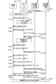
- FIG. 6 is a sequence diagram of handover control according to the embodiment of the X2 handover case.
- the handover control sequence diagram shown in FIG. 6 shows a sequence after the state where each of the mobile stations UE10-1 to 10-n is communicating (step S1022 in FIG. 5).
- the mobile stations UE10-1 to 10-n When the mobile stations UE10-1 to 10-n are communicating, the mobile stations UE10-1 to 10-n and the relay node RN20 are connected to the second radio base station T-DeNB from the communication area of the first radio base station S-DeNB30s. (S2001).
- the relay node RN20 detects that the radio quality between the local station RN20 and the first radio base station S-DeNB 30s has deteriorated (S2002). Then, the relay node RN20 transmits the “Radio Environment Measurement Report (Measurement Report)” message of the local station RN20 to the first radio base station S-DeNB 30s (S2003).
- S2002 the radio quality between the local station RN20 and the first radio base station S-DeNB 30s has deteriorated
- the relay node RN20 transmits the “Radio Environment Measurement Report (Measurement Report)” message of the local station RN20 to the first radio base station S-DeNB 30s (S2003).
- the first radio base station S-DeNB 30s determines a handover to the second radio base station T-DeNB 30t for the relay node RN20. Then, the first radio base station S-DeNB 30s transmits a “Handover request” message to the relay node RN20 to the second radio base station T-DeNB 30t (S2004).
- the relay node RN20 extracts the instance information and context information (information stored in S1004 and S1009 in FIG. 5) of each of the communicating mobile stations UE10-1 to 10-n stored in the local station RN20. Then, the relay node RN20 determines a handover to the second radio base station T-DeNB 30t for the mobile stations UE10-1 to 10-n in communication, and each of the mobile stations UE10-1 to 10-n in communication
- the handover process is autonomously started (S2005).
- the relay node RN20 generates a “Handover Request” message for the mobile stations UE10-1 to 10-n based on the extracted instance information and context information. Then, the relay node RN20 transmits the generated “handover request” message to the second radio base station T-DeNB 30t (S2006). At this time, the relay node RN20 may bundle and transmit “handover request” messages to the mobile stations UE10-1 to 10-n.
- the relay node RN20 suppresses forwarding of user data regarding the mobile stations UE10-1 to 10-n in communication (S2007).
- the second radio base station T-DeNB 30t transmits a “handover request confirmation (Handover Request Ack)” message to the relay node RN20 to the first radio base station S-DeNB 30s (S2008).
- Handover Request Ack Handover Request Ack
- the second radio base station T-DeNB 30t transmits a “handover request confirmation” message for each of the mobile stations UE10-1 to 10-n to the relay node RN20 (S2009). At this time, the second radio base station T-DeNB 30t may bundle and transmit “handover request response” messages to the mobile stations UE10-1 to 10-n.
- Step 2007, the relay node RN20 suppresses transfer of user data related to the mobile stations UE10-1 to 10-n. Therefore, even if the relay node RN20 receives the “handover request confirmation” message for the mobile stations UE10-1 to 10n from the second radio base station T-DeNB30t, it transfers the user data to the second radio base station T-DeNB30t. Do not start processing.
- the first radio base station S-DeNB 30s transmits a “radio resource control connection reconfiguration (RRC Connection Reconf)” message to the relay node RN20 to the relay node RN20 (S2010).
- RRC Connection Reconf radio resource control connection reconfiguration
- the relay node RN20 transmits a “handover complete (Handover“ Complete) ”message (“ radio resource control connection reconfiguration complete (RRC Connection ”Reconf Comp)” message) to the second radio base station T-DeNB 30t ( S2011).
- the relay node RN20 transmits a “handover completion” message (“radio resource control connection reconfiguration completion” message) to each of the mobile stations UE10-1 to 10-n to the second radio base station T-DeNB 30t (S2012). ).
- the second radio base station T-DeNB 30t transmits a “Path switch request” message to the relay node RN20 to the first mobility management device MME 40 (S2013).
- the second radio base station T-DeNB 30t transmits a “path switching request” message for each of the mobile stations UE10-1 to 10-n to the first mobility management apparatus MME40 (S2014).
- the first mobility management device MME 40 transmits a “Modify Bearer Request” message to the gateway 50 to the relay node RN20. Further, the first mobility management device MME 40 receives a “Modify Bearer Response” message from the gateway 50 for the relay node RN20. Then, the first mobility management device MME40 transmits a “path switch request confirmation (Path Switch Request Ack)” message to the relay node RN20 to the second radio base station T-DeNB 30t (S2015).
- Path Switch Request Ack Path switch request confirmation
- the first mobility management device MME 40 transmits a “bearer change request” message to each of the mobile stations UE 10-1 to 10-n to the gateway 50. Also, the first mobility management device MME 40 receives from the gateway 50 a “bearer change response” message for each of the mobile stations UE10-1 to 10-n. Then, the first mobility management device MME40 transmits a “path switching request confirmation” message to each of the mobile stations UE10-1 to 10-n to the second radio base station T-DeNB 30t (S2016).
- the second radio base station T-DeNB 30t transmits an “RN context release” message to the relay node RN20 to the first radio base station S-DeNB 30s (S2017).
- the first radio base station S-DeNB 30s releases the context for the relay node RN20.
- the relay node RN20 when the relay node RN20 detects a radio quality deterioration between the local station RN20 and the first radio base station S-DeNB 30s, the relay node RN20 executes a handover process for the local station RN20. Further, the relay node RN20 autonomously executes handover processing for the mobile stations UE10-1 to 10-n triggered by detection of radio quality degradation between the own station RN20 and the first radio base station S-DeNB30s. .
- the relay node RN20 autonomously starts the handover process of each of the mobile stations UE1-1 to 10-n based on the stored information of the mobile stations UE10-1 to 10-n in communication.
- the relay node RN20 suppresses the forwarding of user data regarding the mobile stations UE10-1 to 10-n in communication. As a result, even if the relay node RN20 receives a “handover request confirmation” message for the mobile stations UE10-1 to 10n from the second radio base station T-DeNB 30t, it does not transfer user data.
- FIG. 7 is a sequence diagram of handover control according to the embodiment of the S1 handover case.
- the second mobility management device MME41 shown in FIG. 7 refers to the mobility management device MME connected to the second radio base station T-DeNB30t. That is, in the case of the S1 handover shown in FIG. 7, the first radio base station S-DeNB 30s is connected to the first mobility management device MME 40, and the second radio base station T-DeNB 30t is connected to the first mobility management device MME 40. Are connected to different second mobility management devices MME41.
- the handover control sequence diagram shown in FIG. 7 shows a sequence after the state where each of the mobile stations UE10-1 to 10-n is communicating (step S1022 in FIG. 5).
- the mobile stations UE10-1 to 10-n When the mobile stations UE10-1 to 10-n are communicating, the mobile stations UE10-1 to 10-n and the relay node RN20 are connected to the second radio base station T-DeNB from the communication area of the first radio base station S-DeNB30s. (S3001).
- the relay node RN20 detects that the radio quality between the local station RN20 and the first radio base station S-DeNB 30s has deteriorated (S3002). Then, the relay node RN20 transmits the “Radio environment measurement report (Measurement Report)” message of the local station RN20 to the first radio base station S-DeNB 30s (S3003).
- the first radio base station S-DeNB 30s determines a handover to the second radio base station T-DeNB 30t for the relay node RN20. Then, the first radio base station S-DeNB 30s transmits a “handover execution required (Handover Required)” message to the relay node RN20 to the first mobility management device MME 40 (S3004).
- the relay node RN20 extracts the instance information and context information (information stored in S1004 and S1009 in FIG. 5) of each of the communicating mobile stations UE10-1 to 10-n stored in the local station RN20. Then, the relay node RN20 determines a handover to the second radio base station T-DeNB 30t for the mobile stations UE10-1 to 10-n in communication, and performs a handover to each of the mobile stations UE10-1 to 10-n in communication The process starts autonomously (S3005).
- the relay node RN20 generates a “Handover Required” message for the mobile stations UE10-1 to 10-n based on the extracted instance information and context information.
- the relay node RN20 transmits the generated “handover execution request” message to the first mobility management device MME40 (S3006).
- the first mobility management device MME40 transmits a “Forward Relocation Request” message to the relay node RN20 to the second mobility management device MME41 (S3007).
- the first mobility management device MME40 transmits a “forward relocation request” message for each of the mobile stations UE10-1 to 10-n to the second mobility management device MME41 (S3008).
- the second mobility management device MME41 transmits a “Handover Request” message to the relay node RN20 to the second radio base station T-DeNB 30t (S3009).
- the second mobility management device MME41 transmits a “handover request” message for each of the mobile stations UE10-1 to 10-n to the second radio base station T-DeNB 30t (S3010).
- the second radio base station T-DeNB 30t transmits a “handover request confirmation (Handover Request Ack)” message to the relay node RN20 to the second mobility management device MME41 (S3011).
- the second radio base station T-DeNB 30t transmits a “handover request confirmation” message for each of the mobile stations UE10-1 to 10-n to the second mobility management apparatus MME41 (S3012).
- the second mobility management device MME41 transmits a “Forward Relocation Response” message to the relay node RN20 to the first mobility management device MME40 (S3013).
- the second mobility management device MME41 transmits a “forward relocation response” message to each of the mobile stations UE10-1 to 10-n to the first mobility management device MME40 (S3014).
- the first mobility management device MME40 transmits a “Handover Command” message for the relay node RN20 to the first radio base station S-DeNB 30s (S3015).
- the first mobility management device MME40 transmits a “handover command” message for each of the mobile stations UE10-1 to 10-n to the relay node RN20 (S3016).
- the first radio base station S-DeNB 30s transmits a “handover command” message for the relay node RN20 to the relay node RN20 (S3017).
- the relay node RN20 suppresses forwarding of user data related to the mobile stations UE10-1 to 10-n in communication (S3018). Therefore, even if the “handover command” message for each of the mobile stations UE10-1 to 10-n is received from the first mobility management device 40, the relay node RN20 transfers the user data to the second radio base station T-DeNB 30t. Do not start.
- the relay node RN20 transmits a “Handover Confirm” message for the local station RN20 to the second radio base station T-DeNB 30t (S3019).
- the relay node RN20 transmits a “handover completion confirmation” message to each of the mobile stations UE10-1 to 10-n to the second radio base station T-DeNB 30t (S3020).
- the second radio base station T-DeNB 30t transmits a “Handover Notify” message to the relay node RN20 to the second mobility management device MME41 (S3021).
- the second radio base station T-DeNB 30t transmits a “handover completion notification” message to each of the mobile stations UE10-1 to 10-n to the second mobility management apparatus MME41 (S3022).
- the second mobility management device MME41 transmits a “Forward / Relocation Complete” message to the relay node RN20 to the first mobility management device MME40 (S3023).
- the second mobility management device MME41 transmits a “forward relocation complete” message for each of the mobile stations UE10-1 to 10-n to the first mobility management device MME40 (S3024).
- the first mobility management device MME40 transmits a “forward relocation completion confirmation (Forward Relocation Complete Ack)” message to the relay node RN20 to the second mobility management device MME41 (S3025).
- the first mobility management device MME40 transmits a “forward relocation completion confirmation” message to each of the mobile stations UE10-1 to 10-n to the second mobility management device MME41 (S3026).
- the first mobility management device MME40 transmits an “RN resource release (RN Release Resource)” message to the first radio base station S-DeNB30s (S3027).
- the first radio base station S-DeNB 30s releases resources for the relay node RN20.
- the relay node RN20 when the relay node RN20 detects a radio quality deterioration between the local station RN20 and the first radio base station S-DeNB 30s, the relay node RN20 executes a handover process for the local station RN20. Further, the relay node RN20 autonomously executes handover processing for the mobile stations UE10-1 to 10-n triggered by detection of radio quality degradation between the own station RN20 and the first radio base station S-DeNB30s. .
- the relay node RN20 autonomously starts the handover process of each of the mobile stations UE1-1 to 10-n based on the stored information of the mobile stations UE10-1 to 10-n in communication.
- the relay node RN20 suppresses the forwarding of user data regarding the mobile stations UE10-1 to 10-n in communication. As a result, even if the “handover command” message for each of the mobile stations UE10-1 to 10-n is received from the first mobility management device 40, the relay node RN20 does not transfer user data.
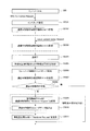
- FIG. 8 is a flowchart of the handover process of the relay node RN when the “radio environment measurement report” message is received from the mobile station UE.
- a “Measurement Report” message is transmitted from the mobile station UE10-x in the mobile stations UE10-1 to 10-n to the relay node RN20. This case will be described below.
- the mobile stations UE10-1 to 10-n in the moving vehicle that are connected to and communicate with the relay node RN20 mounted on the moving vehicle move together with the relay node RN20, the mobile stations UE10-1 to 10-n In many cases, the optimum connection destination node after the movement is still the relay node RN20.
- the third radio base station T-DeNB 30t or the third radio base station T-DeNB 30t that is outside the mobile vehicle is different from the third radio base station T-DeNB 30t. It can be assumed that the radio base station T-DeNB is the optimum connection destination node after movement.
- the relay node RN20 performs the handover process for the mobile station UE10-x based on the “radio environment measurement report” message received from the mobile station UE10-x during the handover control process in the process flow shown in FIG. Run like so.
- Step S4001 of FIG. 8 the relay node RN20 moves from the communication area of the first radio base station S-DeNB30s to the communication area of the second radio base station T-DeNB30t together with the communicating mobile stations UE10-1 to 10-n.
- Step S4001 corresponds to, for example, step 2001 in FIG. 6 and step 3001 in FIG.
- the relay node RN20 starts the handover process of the own station RN20 from the first radio base station S-DeNB30s to the second radio base station T-DeNB30t (S4002).
- the process of S4002 in FIG. 8 corresponds to, for example, the process of steps S2002 and S2003 in FIG. 6 and the process of steps S3002 and S3003 in FIG.
- the relay node RN20 autonomously starts the handover process of each of the mobile stations UE10-1 to 10-n (S4003).
- the processing in step S4003 in FIG. 8 corresponds to, for example, the processing in steps 2005 and S2006 in FIG. 6 and the processing in steps S3005 and S3006 in FIG.
- the relay node RN20 inhibits the process of forwarding user data related to the mobile stations UE10-1 to 10-n in communication to the second radio base station T-DeNB 30t (S4004).
- the process in step S4004 in FIG. 8 corresponds to, for example, the process in step S2007 in FIG. 6 and the process in step S3018 in FIG.
- the relay node RN20 receives a “radio environment measurement report” message from the mobile station UE10-x among the mobile stations UE10-1 to 10-n after the process of step S4004. .
- the relay node RN20 hands over the mobile station UE10-x to the second radio base station T-DeNB 30t based on the “radio environment measurement report” message received from the mobile station UE10-x, or the third radio base station T Determine whether to hand over to DeNB (S4005).
- step S4006 in FIG. 8 corresponds to, for example, the process in step S2012 in FIG. 6 and the process in step S3020 in FIG.
- the relay node RN20 determines to hand over the mobile station UE10-x to the third radio base station T-DeNB (“YES” in step S4005), the relay node RN20 moves the mobile station UE10-x to the third radio base station T-DeNB. A process of handing over to the server is performed (S4007).
- the third radio base station T-DeNB is connected to the same first mobility management device MME40 as the first radio base station S-DeNB, and the first radio base station S-DeNB, the third radio base station T-DeNB, Assume that an X2 connection is established during In this case, the relay node RN20 transmits a “Handover Request” message to the third radio base station T-DeNB, and executes an X2-based handover process for the mobile station UE10-x.
- the third radio base station T-DeNB is connected to a third mobility management device MME different from the first radio base station S-DeNB, and the first radio base station S-DeNB and the third radio base station T-DeNB Assume that no X2 connection has been established.
- the relay node RN20 transmits a “Handover Execution Request (Handover Required)” message to the third mobility management device MME, and executes an S1-based handover process for the mobile station UE10-x.
- the relay node RN20 transmits the user data related to the mobile station UE10-x whose transfer is suppressed in step S4004 to the third radio base station T-DeNB. Forward.
- step S4005 the relay node RN20 executes a process of handing over the mobile stations UE10-1 to 10-n excluding the mobile station UE10-x to the second radio base station T-DeNB30t ( S4008).
- the process in step S4008 in FIG. 8 corresponds to, for example, the process in step S2012 for those other than the mobile station UE10-x in FIG. 6 and the process in step S3020 for other than the mobile station UE10-x in FIG.
- the relay node RN20 executes a handover process for the local station RN20 to the second radio base station T-DeNB 30t (S4009).
- the process in step 4009 in FIG. 8 corresponds to, for example, the process in step S2011 in FIG. 6 and the process in step S3019 in FIG.
- the relay node RN20 completes the handover process for the own station RN20 and the mobile stations UE10-1 to 10-n in communication (S4010).
- the relay node RN20 determines that the mobile station UE10-x is handed over to the second radio base station T-DeNB 30t based on the “radio environment measurement report” message from the mobile station UE10-x.
- the relay node RN20 executes the handover process for the mobile station UE10-x to the second radio base station T-DeNB30t as well as the other mobile stations UE10-1 to 10-n.
- the mobile station UE10-x performs communication via the relay node RN20 and the second radio base station T-DeNB30t, similarly to the other mobile stations UE10-1 to 10-n.
- the relay node RN20 determines that a handover is performed to the third radio base station T-DeNB based on the “radio environment measurement report” message from the mobile station UE10-x. In this case, the relay node RN20 executes a handover process for the mobile station UE10-x to the third radio base station T-DeNB. As a result, after the handover, the mobile station UE10-x performs communication via the third radio base station T-DeNB, unlike the other mobile stations UE10-1 to 10-n.
- FIG. 9 is a hardware configuration diagram of the mobile station UE according to the embodiment.
- the mobile station UE100 illustrated in FIG. 9 corresponds to the mobile stations UE10-1 to 10-n, for example.
- the mobile station UE100 includes a data processing device 101, a universal subscriber identity module (Universal Subscriber Identity Module, USIM) 102, an LTE wireless device 103a, an LTE antenna 104a, and a third generation (3 Generation 3G) wireless device 103b. , A third generation antenna 104b, a keyboard 105, a microphone 106, and a speaker 107 are included.
- a universal subscriber identity module Universal Subscriber Identity Module, USIM
- USIM Universal Subscriber Identity Module
- LTE wireless device 103a an LTE antenna 104a
- 3G Third Generation 3G wireless device
- General-purpose subscriber identification module 102 LTE wireless device 103a, third generation wireless device 103b, keyboard 105, microphone 106, and speaker 107 are connected to data processing device 101.
- the LTE antenna 104a is connected to the LTE wireless device 103a.
- the third generation antenna 104b is connected to the third generation radio apparatus 103b.
- the data processing apparatus 101 includes a processing unit 101a and a memory 101b.
- the processing unit 101a executes various processes based on the program stored in the memory 101b and the telephone number and contractor information stored in the general-purpose subscriber identification module 102.
- the mobile station UE100 includes an LTE radio device 103a and an LTE antenna 104a, and a third generation radio device 103b and a third generation antenna 104b. However, the mobile station UE100 does not have to include the third generation radio apparatus 103b and the third generation antenna 104b.
- FIG. 10 is a hardware configuration diagram of the relay node RN according to the embodiment.
- the relay node RN200 illustrated in FIG. 10 corresponds to the relay node RN20.
- the relay node RN200 includes a control device 201, a layer 2 switch (L2SW) 202, an input / output (I / O) port 203, an analog / digital (A / D) converter 204, an amplifier (AMP) 205, an antenna 206, and a general-purpose subscription.
- a person identification module (USIM) 207 and a baseband processor 208 are included.
- the control device 201 performs call control and monitoring control of each part constituting the relay node RN200. In addition, the control device 201 performs the handover process of the embodiment.
- the control device 201 includes a central processing unit (CPU) 201a and a memory 201b. Various processes by the control device 201 are performed by the central processing unit 201a executing processes in accordance with programs stored in the memory 201b.
- CPU central processing unit
- the control device 201 is connected to the general-purpose subscriber identification module 207 and the layer 2 switch 202.
- the general-purpose subscriber identification module 207 stores telephone numbers and contractor information.
- the layer 2 switch 202 is a network relay device. The layer 2 switch 202 is connected to the control device 201, the baseband processing device 208, and the input / output port 203.
- the baseband processing device 208 executes processing of a digital signal before radio frequency (Radio-Frequency, RF) conversion.
- the baseband processor 208 includes a digital signal processor (DSP) 208a and a memory 208b.
- DSP digital signal processor
- the input / output port 203 is connected to the layer 2 switch 202 and the analog / digital converter 204, the analog / digital converter 204 is connected to the input / output port 203 and the amplifier 205, and the amplifier 205 is connected to the analog / digital converter 204 and the antenna 206. Connected.
- FIG. 11 is a functional configuration diagram of the control device of the relay node RN according to the embodiment.
- the control device 201 includes a central processing unit 201a and a memory 201b.
- the central processing unit 201a includes a communicating mobile station management unit 201a1, a radio quality detection unit 201a2, a handover control unit 201a3, a signal editing unit 201a4, and a signal analysis unit 201a5.
- the memory 201b includes a communicating mobile station information storage unit 201b1.
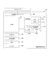
- FIG. 12 is an example of an information table stored for each mobile station UE in the communicating mobile station information storage unit.
- in-communication mobile station information storage unit 201b1 stores instances of mobile stations UE10-1 to 10-n such as temporary cell radio network identifiers (C-RNTI) for each mobile station UE.
- C-RNTI temporary cell radio network identifiers
- the instances of the mobile stations UE10-1 to 10-n communicate with each other when the relay node RN200 receives a “radio resource control connection request” message transmitted by each of the mobile stations UE10-1 to 10-n when starting communication. It is stored in the communicating mobile station information storage unit 201b1 by the middle mobile station management unit 201a1.
- context information of each of the mobile stations UE10-1 to 10-n is stored for each mobile station UE.
- the context information stored in the communicating mobile station information storage unit 201b1 includes S1-MME interface UE identification information (MME UE S1AP ID), UE security capability (UE Security Capabilities), and UE total maximum bit rate (UE Aggregate Maximum Bit). Rate), E-RAB identification information (E-RAB ID), E-RAB level QoS parameters (E-RAB Level QoS Parameters), and uplink GTP tunnel termination point (UL GTP Tunnel Endpoint).
- MME UE S1AP ID UE security capability
- UE total maximum bit rate UE Aggregate Maximum Bit). Rate
- E-RAB identification information E-RAB ID
- E-RAB level QoS parameters E-RAB Level QoS Parameters
- UL GTP Tunnel Endpoint uplink GTP tunnel termination point
- the context information shown in FIG. 12 includes the communicating mobile station information storage unit by the communicating mobile station management unit 201a1 when the relay node RN200 receives the “initial context setting request” message transmitted from the first mobility management device MME40. 201b1.
- the “initial context setting request” message is transmitted after the first mobility management device MME 40 completes the registration process for each of the mobile stations UE 10-1 to 10-n when starting communication.
- the information stored in the communicating mobile station information storage unit 201b1 is stored at the end of each of the mobile stations UE10-1 to 10-n, when an abnormality such as a radio link failure occurs, and from the relay node RN200 to another relay node RN or It is deleted when a handover to the radio base station T-DeNB occurs.
- the radio quality detection unit 201a2 illustrated in FIG. 11 detects radio quality degradation between the relay node Rn200 and the first radio base station S-DeNB 30s. When it is determined from the detection result that the second radio base station T-DeNB 30t has better radio quality than the first radio base station S-DeNB 30s, the radio quality detection unit 201a2 The target cell is notified to the handover control unit 201a3.
- the handover control unit 201a3 illustrated in FIG. 11 receives a handover execution trigger from the radio quality detection unit 201a2, the handover control unit 201a3 performs a handover process to the target cell for the relay node RN200.
- the handover control unit 201a3 transmits a “radio environment measurement report” message to the first radio base station S-DeNB 30s.
- the handover control unit 201a3 When the handover control unit 201a3 receives a handover execution trigger from the radio quality detection unit 201a2, the handover control unit 201a3 performs handover processing to the target cell for each of the communicating mobile stations UE10-1 to 10-n as described in the following ⁇ 1> to Implement as shown in ⁇ 5>.
- the handover control unit 201a3 refers to the in-communication mobile station information storage unit 201b1, and confirms the presence / absence of the mobile stations UE10-1 to 10-n in communication.
- the handover control unit 201a3 performs signal editing of the handover control signal for each of the mobile stations UE10-1 to 10-n.
- the editing unit 201a4 is instructed.
- the handover control unit 201a3 searches for neighboring cell information using physical cell identification information (Physical Cell ID, PCI). Then, the handover control unit 201a3 identifies the radio base station T-DenB that is a handover candidate, and acquires information on the second radio base station T-DeNB 30t such as Public Land Mobile Network (PLMN) and MME Group. Also, X2 connection state information with the second radio base station T-DeNB 30t is acquired.
- PCI Physical Cell ID
- PCI Physical Cell ID
- PLMN Public Land Mobile Network
- MME Group Public Land Mobile Network
- X2 connection state information with the second radio base station T-DeNB 30t is acquired.
- the handover control unit 201a3 determines that the handover is within the same mobility management device MME (the case of X2 handover) when the same MME Group and the X2 connection are established. In other cases, it is determined that a handover between different mobility management devices MME (S1 handover case).
- the handover control signal that the handover control unit 201a3 instructs the signal editing unit 201a4 to edit when determining that the handover is in the same mobility management device MME is a handover request (Handover (Request) message.
- the handover control signal in the case of determining the handover between the two is a “handover execution required (HandoverdRequired)” message.
- the handover control unit 201a3 forwards user data related to the mobile stations UE10-1 to 10-n in communication to the second radio base station T-DeNB 30t (forwarding) Is suppressed.
- the handover control unit 201a3 transmits the “Handover Request” message edited in the above ⁇ 2> to the second radio base station T-DeNB 30t.
- the handover control unit 201a3 uses the notified information of the mobile stations UE10-1 to 10-n and the received signal. Then, the signal editing unit 201a4 is instructed to perform signal editing of the handover control signal. That is, the handover control unit 201a3 instructs the signal editing unit 201a4 to edit the signal of the “handover complete (radio resource control connection reconfiguration complete)” message.
- the handover control unit 201a3 transmits a “handover complete (radio resource control connection reconfiguration complete)” message edited by the signal editing unit 201a4 to the second radio base station T-DeNB 30t.
- the handover control unit 201a3 forwards user data related to the mobile stations UE10-1 to 10-n in communication to the second radio base station T-DeNB 30t (forwarding ).
- the handover control unit 201a3 transmits the “handover execution request” message edited in the above ⁇ 2> to the first mobile base station MME40.
- the signal editing unit 201a4 illustrated in FIG. 11 performs signal editing of the handover control signal when instructed to perform signal editing by the handover control unit 201a3.
- FIG. 13 is a configuration example of a “handover request” message according to the embodiment.
- the signal editing unit 201a4 shows a “Handover Request” message for the mobile stations UE10-1 to 10-n in communication as shown in FIG. Edit with a simple structure.
- the signal editing unit 201a4 captures Old eNB UE X2 AP ID for each of the communicating mobile stations UE10-1 to 10-n stored in the communicating mobile station information storage unit 201b1, and communicates with the mobile station UE10- Repeatedly sets Old eNB UE X2 AP ID for 1 to 10-n.
- the signal editing unit 201a4 uses the Target cell ID and GUMMEI used in the handover process of the relay node RN200, and uses the Target cell ID and GUMMEI in the “handover request” message for the mobile stations UE10-1 to 10-n in communication.
- the signal editing unit 201a4 has the Target Cell ID and GUMMEI extracted based on the physical cell identification information (PCI) notified from the mobile stations UE10-1 to 10-n by the “radio environment measurement report” message. Do not use.
- PCI physical cell identification information
- the signal editing unit 201a4 includes MME UE S1AP ID, UE Security Capabilities, UE Aggregate Maximum Maximum Bit Rate, E-RAB ID, E-RAB Level QoS QoS Parameters, and UL GTP Tunnel Name Endpoint (optional Subscriber Profile ID ID for RAT / Frequency And DL Forwarding) are repeatedly set for the number of mobile stations UE10-1 to 10-n in communication. These pieces of information are notified to the relay node RN200 by the “initial context setting request” message received from the first mobility management device MME40, and stored in the mobile station information storage unit 201b1 during communication for each of the mobile stations UE10-1 to 10-n. Has been.
- the signal editing unit 201a4 creates the security intermediate key KeNB * for each of the mobile stations UE10-1 to 10-n from the physical cell identification information of the current target cell when transmitting the “handover request” message. Then, the signal editing unit 201a4 repeatedly sets AS Security Information for the number of UEs 10-1 to 10-n in communication.
- the signal editing unit 201a4 creates RRC ⁇ Context encoding information for each of the communicating mobile stations UE10-1 to 10-n at the time of transmitting the “handover request” message, and is the same as the number of communicating UEs 10-1 to 10-n, Set repeatedly.
- FIG. 14 is a configuration example of another “handover request” message according to the embodiment.
- the signal editing unit 201a4 displays a “Handover Request” message for the mobile stations UE10-1 to 10-n in communication. It is also possible to edit with the configuration shown in FIG.
- the signal editing unit 201a4 collectively edits information of all the mobile stations UE10-1 to 10-n in communication stored in the mobile station information storage unit 201b1 during communication into one “handover request” message. May be.
- the number of eNB UE X2AP ID indicates the number of mobile stations UE10-1 to 10-n stored in the communicating mobile station information storage unit 201b1.
- ENB UE X2AP ID Information indicates an information element (Initial Element, IE) that can be set repeatedly for the number of eNB UE X2AP IDs of Old eNB UE X2AP ID.
- IE Initial Element
- the UE Context fromation number indicates the number of mobile stations UE10-1 to 10-n stored in the communicating mobile station information storage unit.
- UE Context Information includes MME UE S1AP ID, UE Security Capabilities, AS Security Information, UE Aggregate Maximum Maximum Bit Rate, E-RABs To To Be Setup List (optional Subscriber Profile ID for RAT / Frequency priority) It is set repeatedly for the number of Infromation.
- the signal editing unit 201a4 edits the “handover request” message by the number of mobile stations UE10-1 to 10-n in communication.
- the handover control unit 201a3 transmits the edited “handover request” message to the second radio base station T-DeNB 30t by the number of mobile stations UE10-1 to 10-n in communication.
- the signal editing unit 201a4 collectively edits one “handover request” message for the mobile stations UE10-1 to 10-n in communication. .
- the handover control unit 201a3 transmits the “handover request” message edited together to the second radio base station T-DeNB 30t.
- FIG. 15 is a configuration example of a “handover completion (radio resource control connection reconfiguration completion)” message according to the embodiment.
- FIG. 15 shows a configuration example of a “handover complete (Handover Complete) (radio resource control connection reconfiguration complete (RRC Connection Recont Comp))” message when editing is performed for each of the communicating mobile stations UE10-1 to 10-n. It is shown.
- Handover Complete radio resource control connection reconfiguration complete (RRC Connection Recont Comp)
- the signal editing unit 201a4 can also edit the information elements in the message shown in FIG. 15 as a single handover control signal for the mobile stations UE10-1 to 10-n in communication.
- the handover controller 201a3 may transmit the collectively edited handover control signal to the second radio base station T-DeNB 30t. Therefore, in this case, it is possible to reduce the number of transmissions of the control signal when the mobile station UE in communication under the relay node RN performs handover.
- the signal analyzing unit 201a5 illustrated in FIG. 11 analyzes the handover control signal received from the second radio base station T-DeNB 30t.
- the signal analysis unit 201a5 The received signal is decomposed and analyzed.
- the signal analysis unit 201a5 notifies the handover control unit 201a3 of the analysis result of the handover control signal.
- FIG. 16 is a hardware configuration diagram of the radio base station DeNB according to the embodiment.
- the radio base station DeNB300 illustrated in FIG. 16 corresponds to, for example, the first radio base station S-DeNB30s and the second radio base station T-DeNB30t.
- the radio base station DeNB 300 includes a control device 301, a layer 2 switch (L2SW) 302, an input / output (I / O) port 303, an analog / digital (A / D) converter 304, an amplifier (AMP) 305, an antenna 306, a transmission A road interface 307 and a baseband processor 308 are included.
- L2SW layer 2 switch
- I / O input / output
- a / D analog / digital
- AMP amplifier
- antenna 306 a transmission A road interface 307 and a baseband processor 308 are included.
- the control device 301 performs call control and monitoring control of each part constituting the radio base station DeNB300. In addition, the control device 301 performs the handover process of the embodiment.
- the control device 301 includes a central processing unit (CPU) 301a and a memory 301b. Various processes performed by the control device 301 are performed by the central processing unit 301a executing processes in accordance with programs stored in the memory 301b.
- CPU central processing unit
- the control device 301 is connected to the layer 2 switch 202.
- the layer 2 switch 302 is a network relay device.
- the layer 2 switch 302 is connected to the control device 301, the baseband processing device 308, the input / output port 303, and the transmission path interface 307.
- the baseband processing device 308 executes processing of a digital signal before radio frequency (Radio-Frequency, RF) conversion.
- Baseband processor 308 includes a digital signal processor (DSP) 308a and memory 308b.
- DSP digital signal processor
- the input / output port 303 is connected to the layer 2 switch 302 and the analog / digital converter 304, the analog / digital converter 304 is connected to the input / output port 303 and the amplifier 305, and the amplifier 305 is connected to the analog / digital converter 304 and the antenna 306.
- the transmission path interface 307 is connected to an Internet protocol (Internet Protocol, IP) network outside the layer 2 switch 302 and the radio base station DeNB300.
- IP Internet Protocol
- FIG. 17 is a functional configuration diagram of the control device of the radio base station DeNB according to the embodiment.
- the control device 301 includes a central processing unit 301a and a memory 301b.
- the central processing unit 301a includes a signal analysis unit 301a1, a handover control unit 301a2, and a signal editing unit 301a3.
- the signal analysis unit 301a1 analyzes the handover control signal. For example, when the radio base station DeNB300 is the second radio base station T-DeNB30t, the signal analysis unit 301a1 analyzes the “handover request” message received from the relay node RN20.
- the signal analysis unit 301a1 decomposes and analyzes the bundled received signal.
- the signal analysis unit 301a1 notifies the handover control unit 301a2 of the analysis result of the handover control signal.
- the handover controller 301a2 executes a handover process for the relay node RN20.
- the handover control unit 301a2 executes a handover process for each of the mobile stations UE10-1 to 10-n that are communicating with the relay node RN20.
- the handover control unit 301a2 performs handover processing to the target cell for each of the mobile stations UE10-1 to 10-n. Implement as shown in ⁇ 1> to ⁇ 5> below.
- the handover control unit 301a2 When the handover control signal (“handover request” message) is received from the signal analysis unit 301a1, the handover control unit 301a2 receives the information of the mobile stations UE10-1 to 10-n notified from the signal analysis unit 301a1 and the reception thereof. Handover control is performed based on the signal.
- the handover control unit 301a2 edits the signal editing of the “handover request confirmation” message based on the information of the mobile stations UE10-1 to 10-n notified from the signal analysis unit 301a1 and the received signal.
- the unit 301a3 is instructed.
- the handover control unit 301a2 transmits a “handover request confirmation edited by the signal editing unit 301a3” message to the relay node RN20.
- the handover control unit 301a2 receives the “handover complete (radio resource control connection reconfiguration complete)” message transmitted from the relay node RN20 from the signal analysis unit 301a1. Then, the handover control unit 301a2 performs signal editing of the “path switching request” message on the signal editing unit 301a3 based on the information of the mobile stations UE10-1 to 10-n notified from the signal analysis unit 301a1 and the received signal. Instruct.
- the handover control unit 301a2 transmits the “path switching request” message edited by the signal editing unit 301a3 to the first mobility management device MME40.
- the signal editing unit 301a3 illustrated in FIG. 17 edits the handover control signal based on an instruction from the handover control unit 301a2.
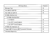
- FIG. 18 is a configuration example of a “handover request confirmation” message according to the embodiment.
- FIG. 19 is a configuration example of another “handover request confirmation” message according to the embodiment.
- the signal editing unit 301a3 creates encoding information of Target ⁇ eNB To Source eNB Transparent Container for each of the communicating mobile stations UE10-1 to 10-n, and the communicating UEs 10-1 to 10-n Repeat for n number of times.
- the number of eNBeUE X2AP ID indicates the number of mobile stations UE for which the handover preparation (Handover Preparation) processing for the mobile stations UE notified by the “handover request” message is successful.
- eNB UE X2AP ID Information Old eNB UE X2AP ID, New eNB UE X2AP ID, E-RABs Admitted List, and Target eNB To Source eNB Transparent Container (optionally, Criticality Diagnostics) is the number of eNB UE X2AP ID Repeated for several minutes.
- the signal editing unit 301a3 performs the “handover request confirmation” message for the number of mobile stations UE10-1 to 10-n in communication. Edit.
- the handover control unit 301a2 transmits the edited “handover request” message to the relay node RN20 by the number of mobile stations UE10-1 to 10-n in communication.
- the signal editing unit 301a3 combines the “handover request” messages into one for the mobile stations UE10-1 to 10-n in communication. Edit.
- the handover control unit 301a2 transmits the “handover request” message edited together to the relay node RN20.
- the mobile station UE100 corresponds to the mobile stations 10-1 to 10-n.
- the relay node 200 corresponds to the relay node 20.
- the radio base station DeNB300 corresponds to the second radio base station T-DeNB30t.
- X2 handover a case will be described as an example where the relay control signal for the mobile station UE100 is edited and transmitted / received collectively by the relay node 200 and the radio base station DeNB300 as shown in FIGS.
- FIG. 20 is an operation flow diagram of the relay node RN from the reception of the “radio resource control connection request” message to the transmission of the “handover request message”.
- FIG. 21 is an operation flowchart of the radio base station DeNB from the reception of the “handover request” message to the transmission of the “handover request confirmation” message.
- FIG. 22 is an operation flow diagram of the relay node RN from the reception of the “handover request confirmation” message to the transmission of the “handover completion” message.
- FIG. 23 is an operation flowchart of the radio base station DeNB from the reception of the “handover completion” message to the completion of path switching.
- the relay node RN200 captures an instance such as C-RNTI of the mobile station 100 (S5001). Then, the communicating mobile station management unit 201a1 stores the supplemented instance of the mobile station UE100 in the communicating mobile station information storage unit 201b1 for each mobile station UE (S5002).
- the communicating mobile station management unit 201a1 stores the context information included in the received message in the communicating mobile station information.
- the information is stored in the unit 201b1 for each mobile station UE (S5003). That is, the communicating mobile station management unit 201a1 stores the context information of the mobile station UE100 in the communicating mobile station information storage unit 201b1 in association with the instance of the mobile station UE100.
- the mobile station UE100 moves from the communication area of the first radio base station S-DeNB30s to the communication area of the radio base station DeNB300 together with the relay node RN200 when the mobile station UE100 is communicating (S5004).
- the radio quality detection unit 201a2 detects radio quality degradation with the first radio base station S-DeNB 30s due to the movement of the local station RN200 (S5005).
- the radio base station DeNB300 determines that the radio quality is better than the first radio base station S-DeNB30s, the radio quality detection unit 201a2 performs handover control of the radio quality degradation and a good target cell of the cell in communication Notification to the unit 201a3.
- the handover control unit 201a3 starts a handover process for the relay node RN200 using the notification from the wireless quality detection unit 201a2 as a trigger (S5006).
- the handover control unit 201a3 refers to the communicating mobile station information storage unit 201b1 (S5007) and confirms the presence / absence of the communicating mobile station UE100 (S5008).
- the handover control unit 201a3 continues the handover process for the relay node RN200.
- the handover control unit 201a3 instructs the signal editing unit 201a4 to edit a “Handover Request” message for the mobile station UE100 in communication. To do.
- the signal editing unit 201a4 edits the “handover request” message (S5009).
- the handover control unit 201a3 suppresses the user data transfer process for the mobile station UE100 in communication (S5010).
- Steps S5009 and S5010 are repeatedly executed for the number of mobile stations UE100 in communication. Therefore, the signal editing unit 201a4 collectively edits “handover request” messages for the number of mobile stations UE100 in communication. The collectively edited “handover request” message is transmitted from the signal editing unit 201a4 to the handover control unit 201a3.
- the handover control unit 201a3 transmits the “handover request” message edited by the signal editing unit 201a4 to the radio base station DeNB300 (S5011).
- the signal analysis unit 301a1 extracts eNB UE X2AP ID Information from the received message (S5012). Further, the signal analysis unit 301a1 extracts UE Context Information (S5013).
- step S5012 The extraction of eNB UE X2AP ID Information in step S5012 is repeated for the number of eNB UE X2AP IDs included in the “handover request” message. Further, the extraction of UE Context Information in step S5013 is repeated for the number of UE Context Information included in the “handover request” message.
- the signal analysis unit 301a1 notifies the handover control unit 301a1 of the extracted information element.
- the handover control unit 301a2 performs handover preparation control for each mobile station UE 100 in communication based on the information element notified from the signal analysis unit 301a1 (S5014). Then, the handover control unit 301a2 instructs the signal editing unit 301a3 to edit the “Handover Request (Acknowledge” message for the mobile station UE100 for which the handover preparation control is successful.
- the signal editing unit 301a3 edits the “handover request confirmation” message based on the instruction from the handover control unit 301a2 (S5015).
- the editing in step 5015 is repeatedly performed for the number of mobile stations UE100 for which handover preparation control is successful. Therefore, the signal editing unit 301a3 collectively edits “handover request confirmation” messages corresponding to the number of mobile stations UE100 for which handover preparation control is successful.
- the “handover request confirmation” message edited together is transmitted from the signal editing unit 301a3 to the handover control unit 301a2.
- the handover control unit 301a2 transmits a “handover request confirmation” message edited together by the signal editing unit 301a3 to the relay node RN200 (S5016).
- the signal analysis unit 201a5 extracts eNB UE X2AP ID Information from the received message (S5017).
- the extraction of eNB UE X2AP ID Information in step S5017 is repeated for the number of eNB UE X2AP IDs included in the “handover request confirmation” message.
- the signal analysis unit 201a5 notifies the handover control unit 201a3 of the extracted information element.
- the handover control unit 201a3 performs handover execution control for each mobile station UE100 based on the information element notified from the signal analysis unit 201a5 (S5018).
- the handover control unit 201a3 suppresses transfer of user data related to the mobile station UE100. Therefore, even if the handover control unit 201a3 receives a “handover request confirmation” message for the mobile station UE100 from the radio base station DeNB300, the handover control unit 201a3 does not start the user data transfer process.
- the handover control unit 201a3 instructs the signal editing unit 201a4 to edit the “Handover Complete” message for the mobile station UE100 that has performed handover execution control.
- the signal editing unit 201a4 edits the “handover completion” message of the mobile station UE100 on which the handover execution control is performed based on the instruction from the handover control unit 201a4.
- the edited “handover request confirmation” message is transmitted from the signal editing unit 201a4 to the handover control unit 201a3.
- the handover control unit 201a3 transmits the “handover completion” message edited by the signal editing unit 201a4 to the radio base station DeNB300 (S5019).
- the signal analysis unit 301a1 analyzes the received “handover completion” message. Then, the signal analysis unit 301a1 transmits the information element obtained by the analysis to the handover control unit 301a2.
- the handover control unit 301a2 performs path switching for the mobile station UE100 with the first mobility management device MME40 and the gateway GW50 based on the information element received from the signal analysis unit 301a1 (S5020).
- the relay node RN200 autonomously performs the handover process for the mobile station UE100 together with the handover process for the local station RN200 when the radio quality deterioration is detected between the local station RN200 and the first radio base station S-DeNB30s. Run it.
- the relay node RN200 autonomously starts the handover process of each mobile station UE100 based on the stored information of the mobile station UE100 in communication.
- the relay node RN200 suppresses each forwarding of user data regarding the mobile station UE100 in communication. As a result, the relay node RN200 does not transfer the user data even if the “handover request confirmation” message for the mobile station UE100 is received from the radio base station DeNB300.
- the handover control signal is edited together for the mobile station 100 in communication and is transmitted / received between the relay node Rn200 and the radio base station DeNB300 that is the target of the handover.
- the embodiment it is possible to reduce the number of times of transmission and reception of the handover control signal for the mobile station UE 100 between the relay node Rn200 and the radio base station DeNB300.
Landscapes
- Engineering & Computer Science (AREA)
- Computer Networks & Wireless Communication (AREA)
- Signal Processing (AREA)
- Mobile Radio Communication Systems (AREA)
Abstract
Description
なお、以下の実施形態では、3GPPで検討されているLTE-Advancedシステムの仕様に適用した場合を一例として説明する。しかしながら、本発明がLTE-Advancedシステムの仕様に適用した場合に限定されることを意図するものではない。
図4に示した無線通信システムには、移動局UE10-1、リレーノードRN20、第1無線基地局S-DeNB30s、第2無線基地局T-DeNB30t、第1移動管理装置MME40、ゲートウェイGW50が含まれる。
なお、図5~図8を参照しながら説明するシーケンスは、一例にすぎず、必ずしも時系列的に処理されなくてもよく、並列的にもしくは個別に実行されてもよい処理が含まれる。また、実施形態のハンドオーバ制御手順は、図5~図8に図示されない処理の付加を排除するものではない。
図9に示した移動局UE100は、例えば、移動局UE10-1~10-nに相当する。
処理部101aは、メモリ101bに格納されたプログラム、および汎用加入者識別モジュール102に格納された電話番号および契約者情報に基づき、各種の処理を実行する。
図10に示したリレーノードRN200は、リレーノードRN20に相当する。
レイヤ2スイッチ202は、ネットワークの中継機器である。レイヤ2スイッチ202は、制御装置201、ベースバンド処理装置208、および入出力ポート203と接続される。
制御装置201には、中央処理部201aおよびメモリ201bが含まれる。
図12は、通信中移動局情報記憶部中に移動局UE毎に格納される情報テーブルの一例である。
同一移動管理装置MME内のハンドオーバ(X2ハンドオーバのケース)では、信号編集部201a4は、通信中の移動局UE10-1~10-nに対する“ハンドオーバ要求(Handover Request)”メッセージを図13に示すような構成で編集する。
実施形態では、同一移動管理装置MME内のハンドオーバ(X2ハンドオーバのケース)では、信号編集部201a4は、通信中の移動局UE10-1~10-nに対する“ハンドオーバ要求(Handover Request)”メッセージを図14に示すような構成で編集することも可能である。
図16に示した無線基地局DeNB300は、例えば、第1無線基地局S-DeNB30sおよび第2無線基地局T-DeNB30tに相当する。
レイヤ2スイッチ302は、ネットワークの中継機器である。レイヤ2スイッチ302は、制御装置301、ベースバンド処理装置308、入出力ポート303、および伝送路インタフェース307と接続される。
制御装置301には、中央処理部301aおよびメモリ301bが含まれる。
Claims (14)
- 第1無線基地局および第1移動管理装置に登録され、移動局と前記第1無線基地局との間の通信を中継するリレーノードであって、
前記リレーノードと前記第1無線基地局との間の無線品質の劣化を検出した時に、前記リレーノードに対するハンドオーバ処理を実施すると共に、前記移動局を前記第1無線基地局から第2無線基地局へハンドオーバすることを決定し、前記移動局に対するハンドオーバ制御信号を前記第2無線基地局または前記第1移動管理装置へ送信する第1の制御部を含むことを特徴とするリレーノード。 - 前記第1の制御部は、複数の移動局に対する前記ハンドオーバ制御信号を1つのハンドオーバ制御信号に纏めて編集し、纏めて編集された前記ハンドオーバ信号を送信することを特徴とする、請求項1に記載のリレーノード。
- 請求項2に記載のリレーノードと、前記リレーノードと接続され通信中の複数の移動局および前記リレーノードに対するハンドオーバ対象の無線基地局とを含む無線通信システムであって、前記無線基地局が、
前記リレーノードから受信した前記複数の移動局に対して1つに纏められたハンドオーバ制御信号を移動局毎に解析し、解析された移動局毎に前記複数の移動局に対するハンドオーバ処理を実行し、ハンドオーバ処理された前記複数の移動局に対するハンドオーバ制御信号を1つのハンドオーバ制御信号に纏めて前記リレーノードに送信する第2の制御部を含むことを特徴とする無線通信システム。 - 前記第1の制御部は、前記無線基地局から受信した前記ハンドオーバ制御信号を解析することを特徴とする請求項3に記載の無線通信システム。
- 前記第1の制御部は、ハンドオーバ要求確認信号を前記第2無線基地局から受信した時に、前記第1無線基地局から受信した前記移動局に関するユーザデータの転送をせずにハンドオーバ制御を実行し、ハンドオーバ完了信号を前記第2無線基地局へ送信することを特徴とする、請求項1に記載のリレーノード。
- 前記第1の制御部は、ハンドオーバ命令信号を前記第1移動管理装置から受信した時に、前記第1無線基地局から受信した前記移動局に関するユーザデータの転送をせずにハンドオーバ制御を実行し、ハンドオーバ確認信号を前記第2無線基地局へ送信することを特徴とする、請求項1に記載のリレーノード。
- 前記第1の制御部は、
前記移動局から受信した無線環境測定報告信号に基づいて、前記第2無線基地局と前記第2無線基地局とは異なる第3無線基地局の何れにハンドオーバするかを決定し、
前記移動局を前記第3無線基地局にハンドオーバすると決定した場合には、前記移動局に対する前記ユーザデータを前記第3無線基地局へ転送してハンドオーバ制御を実行することを特徴とする、請求項5または6に記載のリレーノード。 - 第1無線基地局および第1移動管理装置に登録され、移動局と前記第1無線基地局との間の通信を中継するリレーノードと、前記移動局とが前記第1無線基地局から第2無線基地局へハンドオーバするための無線通信方法であって、前記リレーノードが、
前記リレーノードと前記第1無線基地局との間の無線品質の劣化を検出した時に、前記リレーノードに対するハンドオーバ処理を実施すると共に、前記移動局を前記第1無線基地局から前記第2無線基地局へハンドオーバすることを決定し、前記移動局に対するハンドオーバ制御信号を前記第2無線基地局または前記第1移動管理装置へ送信することを特徴とする無線通信方法。 - 前記リレーノードは、複数の移動局に対する前記ハンドオーバ制御信号を1つのハンドオーバ制御信号に纏めて編集し、纏めて編集された前記ハンドオーバ信号を送信することを特徴とする、請求項9に記載の無線通信方法。
- 前記第2無線基地局は、
前記リレーノードから受信した前記ハンドオーバ制御信号を移動局毎に解析し、
解析された前記移動局毎に前記複数の移動局に対するハンドオーバ処理を実行し、ハンドオーバ処理された前記複数の移動局に対するハンドオーバ制御信号を1つのハンドオーバ制御信号に纏めて前記リレーノードに送信する
ことを特徴とする請求項9に記載の無線通信方法。 - 前記リレーノードは、前記無線基地局から受信した前記ハンドオーバ制御信号を解析することを特徴とする、請求項10に記載の無線通信方法。
- 前記リレーノードは、ハンドオーバ要求確認信号を前記第2無線基地局から受信した時に、前記第1無線基地局から受信した前記移動局に関するユーザデータの転送をせずにハンドオーバ制御を実行し、ハンドオーバ完了信号を前記第2無線基地局へ送信することを特徴とする、請求項8に記載の無線通信方法。
- 前記リレーノードは、ハンドオーバ命令信号を前記第1移動管理装置から受信した時に、前記第1無線基地局から受信した前記移動局に関するユーザデータの転送をせずにハンドオーバ制御を実行し、ハンドオーバ確認信号を前記第2無線基地局へ送信することを特徴とする、請求項8に記載の無線通信方法。
- 前記リレーノードは、
前記移動局から受信した無線環境測定報告信号に基づいて、前記第2無線基地局と前記第2無線基地局とは異なる第3無線基地局の何れにハンドオーバするかを決定し、
前記移動局を前記第3無線基地局にハンドオーバすると決定した場合には、転送を抑止した前記移動局に対する前記ユーザデータを前記第3無線基地局へ転送してハンドオーバ制御を実行する
ことを特徴とする、請求項12または13に記載の無線通信方法。
Priority Applications (4)
| Application Number | Priority Date | Filing Date | Title |
|---|---|---|---|
| EP11873306.2A EP2763466A4 (en) | 2011-09-30 | 2011-09-30 | RELAY NODES, RADIO COMMUNICATION SYSTEM AND RADIO COMMUNICATION METHOD |
| PCT/JP2011/072600 WO2013046447A1 (ja) | 2011-09-30 | 2011-09-30 | リレーノード、無線通信システム、および無線通信方法 |
| JP2013535787A JP5800024B2 (ja) | 2011-09-30 | 2011-09-30 | リレーノード、無線通信システム、および無線通信方法 |
| US14/223,195 US9467920B2 (en) | 2011-09-30 | 2014-03-24 | Relay node, radio communication system, and method |
Applications Claiming Priority (1)
| Application Number | Priority Date | Filing Date | Title |
|---|---|---|---|
| PCT/JP2011/072600 WO2013046447A1 (ja) | 2011-09-30 | 2011-09-30 | リレーノード、無線通信システム、および無線通信方法 |
Related Child Applications (1)
| Application Number | Title | Priority Date | Filing Date |
|---|---|---|---|
| US14/223,195 Continuation US9467920B2 (en) | 2011-09-30 | 2014-03-24 | Relay node, radio communication system, and method |
Publications (1)
| Publication Number | Publication Date |
|---|---|
| WO2013046447A1 true WO2013046447A1 (ja) | 2013-04-04 |
Family
ID=47994551
Family Applications (1)
| Application Number | Title | Priority Date | Filing Date |
|---|---|---|---|
| PCT/JP2011/072600 Ceased WO2013046447A1 (ja) | 2011-09-30 | 2011-09-30 | リレーノード、無線通信システム、および無線通信方法 |
Country Status (4)
| Country | Link |
|---|---|
| US (1) | US9467920B2 (ja) |
| EP (1) | EP2763466A4 (ja) |
| JP (1) | JP5800024B2 (ja) |
| WO (1) | WO2013046447A1 (ja) |
Cited By (4)
| Publication number | Priority date | Publication date | Assignee | Title |
|---|---|---|---|---|
| JP2016006924A (ja) * | 2014-06-20 | 2016-01-14 | 株式会社Nttドコモ | 基地局 |
| JP2017208861A (ja) * | 2011-11-04 | 2017-11-24 | 三菱電機株式会社 | 移動体通信システム |
| JP2019501583A (ja) * | 2015-12-02 | 2019-01-17 | エルジー エレクトロニクス インコーポレイティド | 無線通信システムにおけるマスタ端末及びそのコンパニオン装置のモビリティをサポートする方法及び装置 |
| JP2019506801A (ja) * | 2016-01-21 | 2019-03-07 | ヴェニアム,インコーポレーテッド | 例えば自律型車両のネットワークを含む、移動物体のネットワークにおいてモバイル・アクセス・ポイントのハンドオーバを管理およびトリガするシステムおよび方法 |
Families Citing this family (12)
| Publication number | Priority date | Publication date | Assignee | Title |
|---|---|---|---|---|
| CN103096404B (zh) * | 2011-11-04 | 2018-07-13 | 北京三星通信技术研究有限公司 | 支持组切换的方法及设备 |
| WO2013109008A1 (en) * | 2012-01-19 | 2013-07-25 | Lg Electronics Inc. | The method and apparatus for indicating handover in wireless communication system including mobile relay node |
| JP6055255B2 (ja) * | 2012-09-26 | 2016-12-27 | 株式会社Nttドコモ | 移動通信方法 |
| JP2015095675A (ja) * | 2013-11-08 | 2015-05-18 | 株式会社Nttドコモ | 移動通信方法 |
| US9723543B2 (en) * | 2015-07-08 | 2017-08-01 | Blackberry Limited | Systems and methods for managing a UE-to-network relay |
| JP6546072B2 (ja) * | 2015-11-13 | 2019-07-17 | 京セラ株式会社 | 通信システム、基地局、および中継局 |
| CN114375017A (zh) * | 2016-01-16 | 2022-04-19 | 华为技术有限公司 | 一种切换的方法、基站及终端设备 |
| EP3506674B1 (en) * | 2016-09-30 | 2021-03-31 | Huawei Technologies Co., Ltd. | Handover method, apparatus and system |
| US10028186B1 (en) * | 2017-03-24 | 2018-07-17 | Sprint Communications Company L.P. | Wireless communication system to redirect use equipment (UE) from a wireless relay to a donor base station |
| CN118158772A (zh) | 2018-08-08 | 2024-06-07 | 索尼公司 | 基站、用户设备和方法 |
| JP2024021856A (ja) | 2022-08-04 | 2024-02-16 | キヤノン株式会社 | 移動通信装置及びその制御方法、並びにプログラム |
| WO2025159677A1 (en) * | 2024-01-22 | 2025-07-31 | Telefonaktiebolaget Lm Ericsson (Publ) | Handling of link degradation in wireless backhaul links |
Citations (7)
| Publication number | Priority date | Publication date | Assignee | Title |
|---|---|---|---|---|
| WO2006126261A1 (ja) | 2005-05-25 | 2006-11-30 | Mitsubishi Denki Kabushiki Kaisha | 車輌及び移動体通信システム |
| JP2009534899A (ja) * | 2006-04-19 | 2009-09-24 | ノキア コーポレイション | 第1の基地局から第2の基地局への複数の移動局のハンドオーバ |
| WO2010089949A1 (ja) * | 2009-02-03 | 2010-08-12 | シャープ株式会社 | 移動通信システム、基地局装置、通信制御方法及び通信制御プログラム |
| WO2010146661A1 (ja) * | 2009-06-16 | 2010-12-23 | 富士通株式会社 | 無線通信システム |
| JP2011004374A (ja) | 2009-06-22 | 2011-01-06 | Ntt Docomo Inc | 移動通信方法、無線基地局及びリレーノード |
| JP2011061453A (ja) | 2009-09-09 | 2011-03-24 | Kyocera Corp | 無線通信システム、無線基地局、無線中継局及びハンドオーバ制御方法 |
| JP2011135439A (ja) * | 2009-12-25 | 2011-07-07 | Fujitsu Toshiba Mobile Communications Ltd | 移動中継システム、移動中継局、移動中継方法 |
Family Cites Families (8)
| Publication number | Priority date | Publication date | Assignee | Title |
|---|---|---|---|---|
| JP3912509B2 (ja) * | 2002-06-24 | 2007-05-09 | 日本電気株式会社 | 移動通信システム、無線切替方法、移動基地局、及び携帯端末機 |
| CN101578782B (zh) * | 2006-11-14 | 2013-02-27 | 韩国电子通信研究院 | 利用移动中继站的切换方法 |
| JP4988644B2 (ja) * | 2008-04-24 | 2012-08-01 | 京セラ株式会社 | 中継局、無線通信システムおよび無線通信方法 |
| US8228871B2 (en) * | 2009-03-19 | 2012-07-24 | Telefonaktiebolaget Lm Ericsson (Publ) | Wireless handover optimization |
| US9084150B2 (en) * | 2009-03-20 | 2015-07-14 | Telefonaktiebolaget L M Ericsson (Publ) | Signaling mechanisms for network-relay interface with reduced overhead |
| US9210622B2 (en) * | 2009-08-12 | 2015-12-08 | Qualcomm Incorporated | Method and apparatus for relay backhaul design in a wireless communication system |
| CN101998554A (zh) * | 2009-08-18 | 2011-03-30 | 中兴通讯股份有限公司 | 基于移动中继的切换方法和移动无线中继系统 |
| JP5399860B2 (ja) * | 2009-10-27 | 2014-01-29 | 京セラ株式会社 | 基地局装置、ハンドオーバ制御方法、および無線通信ネットワークシステム |
-
2011
- 2011-09-30 JP JP2013535787A patent/JP5800024B2/ja not_active Expired - Fee Related
- 2011-09-30 EP EP11873306.2A patent/EP2763466A4/en not_active Withdrawn
- 2011-09-30 WO PCT/JP2011/072600 patent/WO2013046447A1/ja not_active Ceased
-
2014
- 2014-03-24 US US14/223,195 patent/US9467920B2/en not_active Expired - Fee Related
Patent Citations (7)
| Publication number | Priority date | Publication date | Assignee | Title |
|---|---|---|---|---|
| WO2006126261A1 (ja) | 2005-05-25 | 2006-11-30 | Mitsubishi Denki Kabushiki Kaisha | 車輌及び移動体通信システム |
| JP2009534899A (ja) * | 2006-04-19 | 2009-09-24 | ノキア コーポレイション | 第1の基地局から第2の基地局への複数の移動局のハンドオーバ |
| WO2010089949A1 (ja) * | 2009-02-03 | 2010-08-12 | シャープ株式会社 | 移動通信システム、基地局装置、通信制御方法及び通信制御プログラム |
| WO2010146661A1 (ja) * | 2009-06-16 | 2010-12-23 | 富士通株式会社 | 無線通信システム |
| JP2011004374A (ja) | 2009-06-22 | 2011-01-06 | Ntt Docomo Inc | 移動通信方法、無線基地局及びリレーノード |
| JP2011061453A (ja) | 2009-09-09 | 2011-03-24 | Kyocera Corp | 無線通信システム、無線基地局、無線中継局及びハンドオーバ制御方法 |
| JP2011135439A (ja) * | 2009-12-25 | 2011-07-07 | Fujitsu Toshiba Mobile Communications Ltd | 移動中継システム、移動中継局、移動中継方法 |
Non-Patent Citations (4)
| Title |
|---|
| "Evolved Universal Terrestrial Radio Access (E-UTRA) and Evolved Universal Terrestrial Radio Access Network (E-UTRAN); Overall Description; Stage 2 (Release 10", 3GPP TS36.300, 24 June 2011 (2011-06-24) |
| "Technical Specification Group Radio Access Network; Evolved Universal Terrestrial Radio Access Network (E-UTRAN); X2 application protocol (X2AP) (Release 10", 3GPP TS36.423, 24 June 2011 (2011-06-24) |
| "Technical Specification Group Services and System Aspects; General Packet Radio Service (GPRS) enhancements for Evolved Universal Terrestrial Radio Access Network (E-UTRAN) access (Relase 10", 3GPP TS23.401, 10 June 2011 (2011-06-10) |
| See also references of EP2763466A4 |
Cited By (5)
| Publication number | Priority date | Publication date | Assignee | Title |
|---|---|---|---|---|
| JP2017208861A (ja) * | 2011-11-04 | 2017-11-24 | 三菱電機株式会社 | 移動体通信システム |
| US10609602B2 (en) | 2011-11-04 | 2020-03-31 | Mitsubishi Electric Corporation | Mobile communication system |
| JP2016006924A (ja) * | 2014-06-20 | 2016-01-14 | 株式会社Nttドコモ | 基地局 |
| JP2019501583A (ja) * | 2015-12-02 | 2019-01-17 | エルジー エレクトロニクス インコーポレイティド | 無線通信システムにおけるマスタ端末及びそのコンパニオン装置のモビリティをサポートする方法及び装置 |
| JP2019506801A (ja) * | 2016-01-21 | 2019-03-07 | ヴェニアム,インコーポレーテッド | 例えば自律型車両のネットワークを含む、移動物体のネットワークにおいてモバイル・アクセス・ポイントのハンドオーバを管理およびトリガするシステムおよび方法 |
Also Published As
| Publication number | Publication date |
|---|---|
| JP5800024B2 (ja) | 2015-10-28 |
| US9467920B2 (en) | 2016-10-11 |
| JPWO2013046447A1 (ja) | 2015-03-26 |
| EP2763466A4 (en) | 2015-05-27 |
| EP2763466A1 (en) | 2014-08-06 |
| US20140206354A1 (en) | 2014-07-24 |
Similar Documents
| Publication | Publication Date | Title |
|---|---|---|
| JP5800024B2 (ja) | リレーノード、無線通信システム、および無線通信方法 | |
| US8532661B2 (en) | Network gateway configured to provide a handover, converting and routing function | |
| KR101223997B1 (ko) | 이동통신시스템 | |
| US9775073B2 (en) | Gateway configured to provide a handover, converting and routing function | |
| CN103228012B (zh) | 移动通信系统 | |
| US8804596B2 (en) | Architecture for termination at access device | |
| JP5225191B2 (ja) | 移動通信システム | |
| CN101730032A (zh) | 一种实现数据前转的方法和一种施主基站 | |
| EP2849492A1 (en) | Base station gateway device, wireless communication system and communication method | |
| CN101867985A (zh) | 长期演进增强系统中的切换方法、中继节点和施主基站 | |
| CN101867984A (zh) | 长期演进增强系统中的切换方法、施主基站和中继节点 | |
| US20180213584A1 (en) | Data transmission method, device and system, and computer storage medium | |
| CN118525530A (zh) | 用于iab网络中的通信的方法及设备 | |
| JP5247881B2 (ja) | 移動通信システム | |
| JP5564092B2 (ja) | 移動通信システム |
Legal Events
| Date | Code | Title | Description |
|---|---|---|---|
| 121 | Ep: the epo has been informed by wipo that ep was designated in this application |
Ref document number: 11873306 Country of ref document: EP Kind code of ref document: A1 |
|
| ENP | Entry into the national phase |
Ref document number: 2013535787 Country of ref document: JP Kind code of ref document: A |
|
| REEP | Request for entry into the european phase |
Ref document number: 2011873306 Country of ref document: EP |
|
| WWE | Wipo information: entry into national phase |
Ref document number: 2011873306 Country of ref document: EP |
|
| NENP | Non-entry into the national phase |
Ref country code: DE |