WO2013046467A1 - 無線通信システム、移動局、基地局及び無線通信システム制御方法 - Google Patents
無線通信システム、移動局、基地局及び無線通信システム制御方法 Download PDFInfo
- Publication number
- WO2013046467A1 WO2013046467A1 PCT/JP2011/072673 JP2011072673W WO2013046467A1 WO 2013046467 A1 WO2013046467 A1 WO 2013046467A1 JP 2011072673 W JP2011072673 W JP 2011072673W WO 2013046467 A1 WO2013046467 A1 WO 2013046467A1
- Authority
- WO
- WIPO (PCT)
- Prior art keywords
- signal
- mobile station
- data
- unit
- control unit
- Prior art date
- Legal status (The legal status is an assumption and is not a legal conclusion. Google has not performed a legal analysis and makes no representation as to the accuracy of the status listed.)
- Ceased
Links
Images






Classifications
-
- H—ELECTRICITY
- H04—ELECTRIC COMMUNICATION TECHNIQUE
- H04W—WIRELESS COMMUNICATION NETWORKS
- H04W52/00—Power management, e.g. Transmission Power Control [TPC] or power classes
- H04W52/02—Power saving arrangements
- H04W52/0209—Power saving arrangements in terminal devices
- H04W52/0212—Power saving arrangements in terminal devices managed by the network, e.g. network or access point is leader and terminal is follower
-
- H—ELECTRICITY
- H04—ELECTRIC COMMUNICATION TECHNIQUE
- H04L—TRANSMISSION OF DIGITAL INFORMATION, e.g. TELEGRAPHIC COMMUNICATION
- H04L1/00—Arrangements for detecting or preventing errors in the information received
- H04L1/0001—Systems modifying transmission characteristics according to link quality, e.g. power backoff
- H04L1/0036—Systems modifying transmission characteristics according to link quality, e.g. power backoff arrangements specific to the receiver
- H04L1/0038—Blind format detection
-
- H—ELECTRICITY
- H04—ELECTRIC COMMUNICATION TECHNIQUE
- H04L—TRANSMISSION OF DIGITAL INFORMATION, e.g. TELEGRAPHIC COMMUNICATION
- H04L5/00—Arrangements affording multiple use of the transmission path
- H04L5/003—Arrangements for allocating sub-channels of the transmission path
- H04L5/0053—Allocation of signalling, i.e. of overhead other than pilot signals
-
- H—ELECTRICITY
- H04—ELECTRIC COMMUNICATION TECHNIQUE
- H04W—WIRELESS COMMUNICATION NETWORKS
- H04W72/00—Local resource management
- H04W72/50—Allocation or scheduling criteria for wireless resources
- H04W72/54—Allocation or scheduling criteria for wireless resources based on quality criteria
- H04W72/542—Allocation or scheduling criteria for wireless resources based on quality criteria using measured or perceived quality
-
- Y—GENERAL TAGGING OF NEW TECHNOLOGICAL DEVELOPMENTS; GENERAL TAGGING OF CROSS-SECTIONAL TECHNOLOGIES SPANNING OVER SEVERAL SECTIONS OF THE IPC; TECHNICAL SUBJECTS COVERED BY FORMER USPC CROSS-REFERENCE ART COLLECTIONS [XRACs] AND DIGESTS
- Y02—TECHNOLOGIES OR APPLICATIONS FOR MITIGATION OR ADAPTATION AGAINST CLIMATE CHANGE
- Y02D—CLIMATE CHANGE MITIGATION TECHNOLOGIES IN INFORMATION AND COMMUNICATION TECHNOLOGIES [ICT], I.E. INFORMATION AND COMMUNICATION TECHNOLOGIES AIMING AT THE REDUCTION OF THEIR OWN ENERGY USE
- Y02D30/00—Reducing energy consumption in communication networks
- Y02D30/70—Reducing energy consumption in communication networks in wireless communication networks
Definitions
- the present invention relates to a radio communication system, a mobile station, a base station, and a radio communication system control method.
- LTE Long Term Evolution
- OFDM Orthogonal Frequency Division Multiplexing
- the peak transmission rate of the downlink is 100 Mb / s or more
- the peak transmission rate of the uplink is 50 Mb / s or more.
- Wireless packet communication is possible.
- 3GPP 3rd Generation Partnership Project
- LTE-A LTE-Advanced
- DRX Discontinuous Reception
- PDCCH Physical Downlink Data Channel
- L1 signal for controlling data transmission / reception a section in which it is not essential.
- the mobile station stops signal processing of the baseband unit.
- the DRX cycle is set when the base station notifies the mobile station of parameters and the like using an RRC (Radio Resource Control) that is an L3 signal at the start of communication. More specifically, the mobile station receives RRC, which is a control signal, and sets DRX according to the DRX parameter notified by RRC.
- the start of DRX is specified by a function of SFN (System Frame Number).
- Other basic parameters of DRX include OnDurationTimer. The section in which the timer is running is called OnDuration, and the mobile station cannot shift to the power saving mode in this section. And it is specified that the mobile station can shift to the power saving mode in a section where the timer is not running, that is, a section other than OnDuration.
- DS Dynamic Scheduling
- SPS Semi-Persistent Scheduling
- the radio resource used in the PDCCH is designated for both uplink and downlink communications
- the PDSCH Physical Downlink Shared Channel
- the SPS notifies in advance of a predetermined period having a predetermined transmission period before actually executing communication.
- the base station transmits an activation command by PDCCH, and communication is started by notifying the mobile station which radio resource is to be used continuously. Further, the base station stops communication by transmitting a release command by PDCCH to the mobile station, for example.
- the base station allocates PDCCH to a radio resource called CCE (Control Channel Element) and transmits it.
- CCE Control Channel Element
- the base station generates a PDCCH for each mobile station, assigns the number of CCEs corresponding to the PDCCH required for the control information, and is defined in a physical resource corresponding to the assigned CCE in a DCI format (Downlink Control Information format).
- DCI format Downlink Control Information format
- Control information is mapped and transmitted. For example, for mobile stations located in places with poor channel quality, such as near cell boundaries, an MCS with a low MCS (Modulation and Coding Scheme) level needs to be set to satisfy the required reception quality. .
- the base station transmits a PDCCH that occupies more CCEs, for example, 8 CCEs.
- the base station transmits a smaller number of CCEs, for example, a PDCCH that occupies one CCE.
- mapping to a physical resource whether to map to a cell specific area or to a mobile station specific area is defined depending on the type of control information. An area where the PDCCH is mapped to the physical resource is called a search space.
- the base station superimposes PDCCH for each mobile station on one subframe and transmits it simultaneously.
- the number of CCEs occupied by one PDCCH for mobile stations is called an aggregation level
- the number of CCEs occupied by all PDCCHs is called an aggregation size.
- the base station does not notify the mobile station of information on which physical resource the PDCCH is mapped to. Therefore, the mobile station needs to detect whether or not there is a PDCCH addressed to itself in a subframe including the PDCCH. This process is called blind decoding. Specifically, the mobile station detects the PDCCH addressed to itself by attempting to detect and decode the PDCCH for each aggregation level in each search space set in the subframe. Since such blind decoding is performed in the baseband part of the mobile station, it consumes power of the mobile station. Therefore, in order to reduce power consumption in the mobile station, it is preferable to reduce the number of times of blind decoding.
- the traffic is characterized in that it appears as continuous traffic due to intermittent traffic generated from each application. Therefore, when a large number of applications intermittently generate data, the mobile station appears to have continuous traffic. For this reason, when conventional DRX is used, it is necessary to set OnDuration to be long, and the mobile station cannot shift to the power saving mode. Further, since the mobile station and the section not monitoring the PDCCH are simply set according to a regular pattern, the blind station monitors the maximum number of types of PDCCH when monitoring the PDCCH. For this reason, in the conventional method, in the section where PDCCH monitoring is indispensable, the maximum number of PDCCHs are always continuously monitored.
- 3GPP TR 36.913 “Requirements for further advancements for Evolved Universal Terrestrial Radio Access (E-UTRA) (LTE-Advanced)”, V9.0.0, Release 9, December 2009.
- 3GPP TR36.912 “Feasibility study for further advancements for E-UTRA (LTE-Advanced)”, V9.3.0, Release 9, June 2010.
- 3GPP TS36.133 “Requirements for support of radio resource management”, V10.3.0, Release 10, June 2011.
- 3GPP TS36.213 “Physical layer procedures”, V10.2.0, Release 10, June 2011.
- 3GPP TS36.300 “Evolved Universal Terrestrial Radio Access (E-UTRA) and Evolved Universal Terrestrial Radio Access Network (E-UTRAN)”, V10.4.0, Release 10, June 2011.
- the disclosed technology has been made in view of the above, and an object thereof is to provide a radio communication system, a mobile station, a base station, and a radio communication system control method that efficiently reduce power consumption.
- the radio communication system, the mobile station, the base station, and the radio communication system control method disclosed in the present application are, in one aspect, the radio communication system having a mobile station and a base station.
- the base station includes a control unit that transmits a signal including a control signal that triggers a change in decoding processing to the mobile station based on a measurement result of the data amount of the mobile station.
- the mobile station selects a signal format to be decoded in response to a control signal received from the base station, and performs decoding on a signal having the selected format among signals received from the base station.
- a decoding unit for detecting a control signal addressed to the own apparatus.
- wireless communication system mobile station, base station, and wireless communication system control method disclosed in the present application, there is an effect that power consumption can be efficiently reduced.
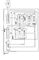
- FIG. 1 is a block diagram of the mobile station according to the first embodiment.
- FIG. 2 is a block diagram of the base station according to the first embodiment.
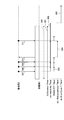
- FIG. 3 is a diagram for explaining a timer in DRX.
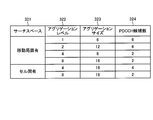
- FIG. 4 is a diagram for explaining the number of PDCCH candidates.
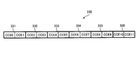
- FIG. 5 is a mapping example of PDCCH.
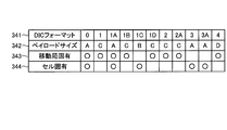
- FIG. 6 is a diagram showing the correspondence between each DCI format and the search space.
- FIG. 7 is a diagram for explaining the number of times of blind decoding.
- FIG. 8 is a diagram for explaining the transition of the DCI format to be decoded in the wireless communication system according to the first embodiment.
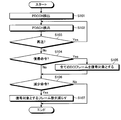
- FIG. 9 is a flowchart of blind decoding control in the mobile station according to the first embodiment.
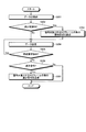
- FIG. 10 is a flowchart of blind decoding control in the base station according to the first embodiment.
- FIG. 11 is a diagram for explaining the transition of the DCI format to be decoded in the wireless communication system according to the second embodiment.
- FIG. 12 is a diagram for explaining the transition of the DCI format to be decoded in the wireless communication system according to the third embodiment.
- FIG. 13 is a flowchart of blind decoding control in the mobile station according to the third embodiment.
- FIG. 14 is a flowchart of the blind decoding control in the base station according to the third embodiment.
- FIG. 15 is a diagram for explaining the transition of the DCI format to be decoded in the wireless communication system according to the fourth embodiment.
- FIG. 16 is a flowchart of blind decoding control in a mobile station according to Modification 4-2.
- FIG. 17 is a diagram for explaining the transition of the DCI format to be decoded in the wireless communication system according to the fifth embodiment.
- FIG. 18 is a flowchart of blind decoding control in the mobile station according to the fifth embodiment.
- FIG. 19 is a flowchart of blind decoding control in the base station according to the fifth embodiment.
- FIG. 20 is a diagram for explaining the transition of the DCI format to be decoded in the wireless communication system according to the first embodiment.
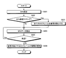
- FIG. 21 is a flowchart of the blind decoding control when the mobile station according to the sixth embodiment receives the SPS.
- FIG. 22 is a hardware configuration diagram of the mobile station.
- FIG. 23 is a hardware configuration diagram of the base station.
- FIG. 1 is a block diagram of the mobile station according to the first embodiment.
- FIG. 2 is a block diagram of the base station according to the first embodiment.
- the mobile station 1 and the base station 2 communicate with each other using DS (Dynamic Scheduling).
- DS Dynamic Scheduling
- the mobile station 1 includes a transmission / reception unit 11, a control unit 12, and an uplink transmission unit 13.
- the control unit 12 includes a control plane unit 110 and a data plane unit 120.
- the control plane unit 110 includes a PDCCH (Physical Downlink Data Channel) processing unit 111, a blind decoding control unit 112, and a timer control unit 113.
- the data plane unit 120 includes a PDSCH (Physical Downlink Shared Channel) processing unit 121 and a HARQ (Hybrid Automatic Repeat Request) management unit 122.
- PDSCH Physical Downlink Shared Channel
- HARQ Hybrid Automatic Repeat Request
- the transmission / reception unit 11 transmits / receives a radio signal to / from a base station 2 described later via an antenna.
- the transmission / reception unit 11 receives from the base station 2 an RRC (Radio Resource Control) that is an L3 signal that is a control signal for notifying the DRX setting conditions.
- the RRC includes a DRX cycle, a timer condition to be started, and the like.
- the transmission / reception unit 11 transmits the received RRC to the timer control unit 113.
- the transmission / reception unit 11 receives a signal including PDCCH and PDSCH from the base station 2.
- the transmission / reception unit 11 outputs the received signal to the blind decoding control unit 112 and the PDSCH processing unit 121.
- the transmission / reception unit 11 receives from the base station 2 a signal indicating that the buffer of the base station 2 is empty.
- buffer status indicator indicating that the buffer is empty by a flag which is 1-bit information added to the PDCCH having one of the predetermined DCI formats. Called “BSI”)
- the DCI format will be described in detail later.
- any format may be used as the DIC format of the PDCCH to which the flag indicating that the buffer of the base station 2 is empty is attached.
- DCI formats 1, 1A, 2, 2A are used among the DCI formats described later.
- the transmission / reception unit 11 receives a notification of downlink data re-arrival from the base station 2.
- the transmission / reception unit 11 receives a control signal “Msg0” transmitted using the DCI format 1A, thereby receiving notification of re-arrival of downlink data.
- Msg0 is a signal for the base station 2 to instruct the mobile station 1 to execute random access.
- the base station 2 performs random access to the mobile station 1 so as to ensure uplink synchronization of the mobile station 1 in order to receive ACK (ACKnowledgement) / NACK (Negative ACKnowledgement) from the mobile station 1 for downlink data.
- Msg0 is transmitted for the purpose of making it happen.
- Msg0 is reused as a control signal for switching to normal PDCCH monitoring.
- uplink synchronization of the mobile station 1 has already been secured, random access is not executed.
- uplink synchronization of the mobile station 1 cannot be ensured, random access is executed. Then, the transmission / reception unit 11 notifies the blind decoding control unit 112 that Msg0 has been received from the base station 2.
- the transmission / reception unit 11 receives NACK and other data from the upstream transmission unit 13. Then, the transmission / reception unit 11 transmits the NACK and other data received from the uplink transmission unit 13 to the base station 2.
- the timer control unit 113 receives an RRC input from the transmission / reception unit 11. Then, the timer control unit 113 obtains the DRX start timing from the DRX cycle and the function using the SFN (System Frame Number) and the identifier of the own device. Then, the timer control unit 113 notifies the PDCCH processing unit 111 and the blind decoding control unit 112 of the DRX start timing. Furthermore, the timer control unit 113 starts a timer specified by RRC from the start subframe, and measures the time determined by each timer. For example, the timer starts a timer as shown in FIG. FIG. 3 is a diagram for explaining a timer in DRX.
- Data 307 to 309 and 311 represent data including the PDCCH transmitted from the base station 2.
- Data 309 represents data that failed to be received.
- NACK 310 is a negative response notifying that reception of data 309 has failed.
- the data 311 is data obtained by receiving the NACK 310 and retransmitting the data 309 by the base station 2.
- OnDuration Timer 301 measures a section of OnDuration 306, which is a section in which reception of PDCCH is essential. That is, since the PDCCH monitoring is not essential in the section where the OnDuration Timer 301 is not rotating, in other words, the section other than the OnDuration 306, the mobile station 1 can transition to the power saving mode.
- the drx-Inactivity Timer 302 is activated or restarted when receiving the PDCCH that notifies the arrival of new data (excluding retransmission). For example, when the data 307 to 309 and 311 including the PDCCH are received from the base station 2, the drx-Inactivity Timer 302 is activated or restarted. Therefore, even when the drx-inactivity timer 302 is activated, monitoring of the PDCCH is essential, and the transition to the power saving mode cannot be made. That is, as shown in FIG. 3, when the drx-Inactivity Timer 302 is rotated beyond the section of OnDuration 306, it cannot transition to the power saving mode during that time.
- the HARQ RTT Timer 303 is activated or restarted regardless of new data or retransmitted data, and manages the HARQ RTT (Round Trip Time) that determines data reception failure.
- the HARQ RTT Timer 303 expires after the reception of the data 309 fails, the mobile station 1 transmits a NACK 310 to the base station 2.
- the drx-Retransmission Timer 304 is activated when the HARQ RTT Timer 303 expires and data reception is not successful, and retransmission is performed while the timer is activated. Therefore, the PDCCH monitor is indispensable even during this section, and the mode cannot be shifted to the power saving mode.
- Short DRX is an optional section that can be set.
- This Short DRX section is a section that is set to immediately transition to a section where PDCCH monitoring is indispensable by starting drx-Inactivity Timer 302 when data is received in that section. realizable.
- drxShortCycle Timer 305 starts when rx-Retransmission Timer 304 expires and manages the section of Short DRX. When drxShortCycle Timer305 expires, it transitions directly to Long DRX.
- Long DRX is a section that can make a transition to the power saving mode.
- OnDuration Timer 301 drx-Inactivity Timer 302, and drx-Retransmission Timer 304 is confirmed by timer control unit 113, control unit 12 causes mobile station 1 to transition to the power saving mode.
- the section in which any of OnDuration Timer 301, drx-Inactivity Timer 302, or drx-Retransmission Timer 304 is activated is called “Active Time”.
- the timer control unit 113 notifies the HARQ management unit 122 of the expiration of the HARQ RTT Timer 303 and the start of the drx-Retransmission Timer 304.
- the timer control unit 113 notifies the blind decoding control unit 112 of the expiration of the OnDuration Timer 301 and the expiration of the drx-Inactivity Timer 302.
- the blind decoding control unit 112 receives an input of DRX start timing from the timer control unit 113. And the blind decoding control part 112 performs blind decoding with respect to PDCCH of all formats with a possibility of reception at the start timing of received DRX. When blind decoding is performed and a PDCCH addressed to the own apparatus is detected, blind decoding control section 112 outputs the detected PDCCH to PDCCH processing section 111.
- the blind decoding control unit 112 performs blind decoding by reducing the decoding target to only the PDCCH in a predetermined DCI format. In this embodiment, only 0, 1A, and 1C of the DCI format described later are targeted for decoding. Also in this case, the blind decoding control unit 112 outputs the detected PDCCH to the PDCCH processing unit 111 when performing blind decoding and detecting the PDCCH addressed to the own device.
- the blind decoding control unit 112 As a method for the blind decoding control unit 112 to know which DCI format is to be decoded, there is a method of receiving notification by signaling such as RRC from the base station 2 before starting communication. In addition, as a method of not receiving notification from the base station 2, when limiting the DCI format to be decoded in the blind decoding control unit 112, it is defined in advance that only “0, 1A, 1C” is to be decoded. You may keep it.
- FIG. 4 is a diagram for explaining the number of PDCCH candidates.
- FIG. 5 is an example of PDCCH mapping.
- FIG. 6 is a diagram showing the correspondence between DCI formats and search spaces.
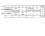
- FIG. 7 is a diagram for explaining the number of times of blind decoding.
- the blind decoding control unit 112 performs blind decoding on the search space indicated by the search space 321.
- the aggregation level 322 indicates the number of CCEs occupied by the PDCCH for the mobile station 1. For example, if the aggregation level 322 is 2, the PDCCH for the mobile station 1 occupies two CCEs.
- the aggregation size 323 is the number of CCEs occupied by all PDCCHs included in the signal.
- PDCCHs 331 to 336 with an aggregation level of 2 can be mapped in the aggregation size 330. That is, in the aggregation size 330, six candidates PDCCH 331 to 336 can be selected as PDCCH candidates.
- the blind decoding control unit 112 detects the PDCCH addressed to itself by repeatedly selecting and decoding each candidate at each aggregation level for each search space. For example, if the aggregation size is 330 as shown in FIG. 5, the PDCCHs 331 to 336 that are candidates for the PDCCH addressed to the own device are sequentially selected and the decoding is repeated. A process in which decoding is sequentially repeated for a candidate that may be a PDCCH addressed to the own apparatus is called blind decoding.
- the DCI format is described in line 341, and the payload size corresponding to each DCI format is described in line 342. Further, lines 343 and 343 indicate to which search space each DCI format may be mapped. As shown in FIG. 6, for example, in LTE-A, there are eleven types of DIC formats, 0, 1, 1A, 1B, 1C, 1D, 2, 2A, 3, 3A, and 4.
- DCI format 0 has a payload size of A and is mapped to both a mobile station specific and cell specific search space.
- DCI format 1 has a payload size of C and is mapped only to a search space unique to the mobile station.
- the DCI format 1A has a payload size of A and is mapped to both the mobile station specific and cell specific search spaces.
- DCI format 1B has a payload size of C and is mapped only to a search space unique to the mobile station.
- the DCI format 1C has a payload size of B and is mapped only to a cell-specific search space.
- the DCI format 1D has a payload size of C and is mapped only to a search space unique to the mobile station.
- DCI format 2 has a payload size of C and is mapped only to a search space unique to the mobile station.
- the DCI format 2A has a payload size of C and is mapped only to a search space unique to the mobile station.
- DCI format 3 has a payload size of A and is mapped only to a cell-specific search space.
- the DCI format 3A has a payload size of A and is mapped only to a cell-specific search space.
- DCI format 4 has a payload size of D and is mapped only to a search space unique to the mobile station.
- Each DCI format is classified into four types (A to D) according to the payload size as shown in FIG.
- the blind decoding control unit 112 needs to perform decoding and detection for each format to be decoded.
- the payload size is the same, it is possible to determine which format of the PDCCH addressed to the own device by one decoding, so that the blind decoding control unit 112 decodes the PDCCH of the format having the same payload size collectively. And detection can be performed.
- FIG. 7 shows the number of PDCCH candidates for the format group by collecting the formats for each payload size for each search space.
- a row 351 represents the payload size.
- the upper row of the column corresponding to each payload size in the row 352 and the row 353 represents the corresponding format, and the lower row represents the number of PDCCH candidates.
- formats 0 and 1A are mapped to a mobile station-specific search space in a group with a payload size of A, and the number of PDCCH candidates is 16.
- formats 0, 1A, 3 and 3A that are mapped to a cell-specific search space in a group having a payload size of A, and the number of PDCCH candidates is six.
- the sum of the number of candidates in each payload size is 48 in the mobile station-specific search space, 12 in the cell-specific search space, and 60 in total.
- the blind decoding control unit 112 can complete decoding of PDCCHs of all formats if decoding is performed at most 60 times.
- LTE-A has been described as an example.
- all formats can be decoded with a maximum of 44 decoding operations. Decoding of the PDCCHs can be completed.
- the blind decoding control unit 112 When the format to be decoded is not reduced, the blind decoding control unit 112 performs decoding for up to 60 times in LTE-A and up to 44 times in LTE in order to set PDCCHs of all formats as decoding targets. It will be.
- the format to be decoded when the format to be decoded is reduced is set to DCI formats 0, 1A, and 1C.
- DCI format 0 is a control signal for PUSCH (Physical Uplink Shared Channel) transmission.
- the DCI format 1A is a control signal for supporting compact PDSCH transmission and random access start.
- the DCI format 1C is a very compact control signal for PDSCH transmission such as broadcast information.
- the mobile station 1 can transmit data from its own device. Moreover, the blind decoding control part 112 can acquire Msg0 for switching to a normal PDCCH monitor by detecting DCI format 1A. Further, since the blind decoding control unit 112 detects the DCI format 1C, the mobile station 1 can acquire broadcast information.
- the blind decoding control unit 112 is an example of a “decoding unit”.
- the PDCCH processing unit 111 receives the PDCCH addressed to itself from the blind decoding control unit 112. Then, the PDCCH processing unit 111 performs processing according to the received PDCCH. For example, when the reception of the PDSCH is instructed by the PDCCH, the PDSCH processing unit 121 is instructed to receive the PDSCH from the transmission / reception unit 11 and perform processing. In addition, transmission of uplink data and processing for broadcast information are performed.
- the PDCCH processing unit 111 is an example of a “signal processing unit”.
- the PDSCH processing unit 121 receives an instruction from the PSCCH processing unit 111 to receive and process the PDSCH from the transmission / reception unit 11. Then, the PDSCH processing unit 121 receives the PDSCH from the transmission / reception unit 11. Then, the PDSCH processing unit 121 processes the received PDSCH and forwards the data to an upper layer such as MAC (Medium Access Control). In addition, the PDSCH processing unit 121 notifies the processing result to the HARQ management unit 122.
- an upper layer such as MAC (Medium Access Control).
- MAC Medium Access Control
- the HARQ management unit 122 receives from the timer control unit 113 a notification that the HARQ RTT Timer 303 has expired and the drx-Retransmission Timer 304 has started. Also, the HARQ management unit 122 receives a notification of the PDSCH processing result by the PDSCH processing unit 121. Then, the HARQ management unit 122 notifies the upstream transmission unit 13 of a retransmission request execution command while the HARQ RTT Timer 303 expires and the drx-Retransmission Timer 304 is started.
- control unit 12 processes the data processed by the PDSCH processing unit 121 in each layer such as MAC, RLC, PDCP, and provides the data to the user. Furthermore, the control unit 12 performs processing in each layer on the audio data input from the user and transmits the processed data to the uplink transmission unit 13.
- the uplink transmission unit 13 receives a retransmission request execution command from the HARQ management unit 122, generates a NACK, and transmits the generated NACK to the base station 2 via the transmission / reception unit 11. Further, when the uplink transmission unit 13 receives data input from the user processed by the control unit 12, the uplink transmission unit 13 transmits the data to the base station 2 via the transmission / reception unit 11.
- the base station 2 includes a higher station transmitting / receiving unit 21, a control unit 22, a scheduling unit 23, and a transmitting / receiving unit 24.
- the control unit 22 includes a control plane unit 210 and a data plane unit 220.
- the control plane unit 210 includes a buffer control unit 211, a blind decoding control unit 212, a timer control unit 213, and a signal generation unit 214.
- the base station 2 is connected to the upper station 3 via a network.
- the upper station transmission / reception unit 21 transmits / receives data to / from the upper station 3 via the network.
- the upper station transmitting / receiving unit 21 outputs the data received from the upper station 3 to the buffer control unit 211. Further, the upper station transmitting / receiving unit 21 receives data from the signal generating unit 214. Then, the upper station transmission / reception unit 21 transmits the received data to the upper station 3.
- the buffer control unit 211 receives data input from the higher-level station transmission / reception unit 21. Then, the buffer control unit 211 outputs a data storage instruction to the buffer unit 221 together with the data.
- the buffer control unit 211 measures the amount of data stored in the buffer unit 221. Then, the buffer control unit 211 determines whether or not the buffer unit 221 is empty. When the buffer control unit 211 determines that the buffer unit 221 is empty, the buffer control unit 211 notifies the blind decoding control unit 212 that the buffer unit 221 is empty. When the buffer control unit 211 receives data input from the higher-level station transmission / reception unit 21 while the buffer unit 221 is empty, the buffer control unit 211 notifies the blind decoding control unit 212 of the re-arrival of the downlink data.
- the buffer control unit 211 is an example of a “data amount measurement unit”.
- the buffer unit 221 analyzes BSR (Buffer Status Reporting) transmitted from the mobile station 1 and measures the amount of data staying in the buffer of the mobile station 1.
- BSR Buffer Status Reporting
- the blind decoding control unit 212 receives a notification from the buffer control unit 211 that the buffer unit 221 is empty. Then, the blind decoding control unit 212 instructs the signal generation unit 214 to transmit that the buffer is empty. By issuing this instruction, the blind decoding control unit 212 can grasp that the mobile station 1 restricts the DCI format to be decoded. Thereby, the base station 2 confirms the DCI format which is the decoding target of the mobile station 1 to the blind decoding control unit 212, and transmits the PDCCH having the other DIC format.
- the blind decoding control unit 212 receives the re-arrival of the downlink data from the buffer control unit 211. Then, the blind decoding control unit 212 instructs the signal generation unit 214 to transmit re-arrival of downlink data. By issuing this instruction, the blind decoding control unit 212 can grasp that the mobile station 1 is intended to decode all types of DCI formats that may be received.
- This blind decoding control unit 212 is an example of a “control unit”.
- the timer control unit 213 receives from the scheduling unit 23 the DRX cycle of communication performed with the mobile station 1 and the data transmission cycle. Then, the timer control unit 213 notifies the scheduling unit 23 of data transmission timing. The timer control unit 213 notifies the scheduling unit 23 of the timing of the DRX cycle.
- the signal generation unit 214 receives from the scheduling unit 23 a DRX cycle for communication with the mobile station 1. Then, the signal generation unit 214 generates RRC signaling including the DRX cycle. Then, the signal generation unit 214 outputs the generated RRC signaling to the transmission / reception unit 24.
- the signal generation unit 214 generates a PDCCH that is a control signal for controlling the mobile station 1.
- the signal generation unit 214 acquires transmission data from the buffer unit 221 and generates a PDSCH.
- the signal generation unit 214 outputs the PDCCH to the transmission / reception unit 24.
- the signal generation unit 214 attaches the PDSCH to the generated PDCCH and outputs it to the transmission / reception unit 24.
- the signal generation unit 214 receives a retransmission request from the HARQ management unit 222. Then, the signal generation unit 214 generates again the data that has received the retransmission request. Thereafter, the signal generation unit 214 outputs the generated signal to the transmission / reception unit 24.
- the signal generation unit 214 receives an instruction to transmit that the buffer is empty from the blind decoding control unit 212. Then, the signal generation unit 214 generates a signal by adding a flag indicating that the buffer is empty to the PDCCH having a predetermined DCI format. Then, the signal generation unit 214 outputs a signal obtained by adding a flag to the generated PDCCH to the transmission / reception unit 24.
- the PDCCH to which the flag is added may be used as the notification PDCCH after transmitting the last PDSCH before the buffer unit 221 becomes empty, or is accompanied when the last PDSCH is transmitted. PDCCH may be used.
- the signal generation unit 214 receives an instruction from the blind decoding control unit 212 to transmit a notification of downlink data re-arrival. Then, the signal generation unit 214 generates a DCI format 1A PDCCH that transmits a control signal Msg0, and outputs the PDCCH to the transmission / reception unit 24.
- the re-arrival of the downlink data is notified by transmitting Msg0 using the DCI format 1A, but the signal used for the notification is not limited to this.
- the signal generation unit 214 is an example of a “signal transmission unit”.
- the buffer unit 221 receives an input of a data storage instruction from the buffer control unit 211 together with the data.
- the buffer unit 221 stores and accumulates the received data. Further, the data accumulated in the buffer unit 221 is reduced by being acquired by the signal generation unit 214.
- the HARQ management unit 222 receives the input of the NACK transmitted from the mobile station 1 from the transmission / reception unit 24. Then, the HARQ management unit 222 notifies the signal generation unit 214 of a retransmission request for transmission data immediately before receiving the NACK.
- the scheduling unit 23 stores a radio transmission scheduling algorithm. And the scheduling part 23 calculates
- the scheduling unit 23 instructs the transmission / reception unit 24 to start and end transmission of a signal including the PDCCH in response to the timing of the DRX cycle.
- the transmission / reception unit 24 transmits / receives a radio signal to / from the mobile station 1 via the antenna.
- the transmission / reception unit 24 transmits the RRC signaling received from the signal generation unit 214 to the mobile station 1.
- the transmission / reception unit 24 receives from the scheduling unit 23 the start of transmission of a signal including the PDCCH.
- the transmission / reception unit 24 receives an input of a signal including the PDCCH from the signal generation unit 214.
- the signal containing PDCCH is transmitted to the mobile station 1 at the timing designated by the scheduling unit 23.
- the transmission / reception unit 24 receives data from the mobile station 1. Then, the transmission / reception unit 24 outputs the received data to the signal generation unit 214. Further, the transmission / reception unit 24 receives NACK from the mobile station 1 via the antenna. In this case, the transmission / reception unit 24 outputs the received NACK to the HARQ management unit 222.
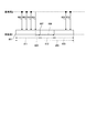
- FIG. 8 is a diagram for explaining the transition of the DCI format to be decoded in the wireless communication system according to the first embodiment.
- FIG. 8 shows the passage of time as it goes to the right toward the page.
- the section 400 in FIG. 8 represents Active Time.
- Time 401 is the DRX start timing calculated by the timer control unit 113 using a function of common information such as the SFN and the identifier of the own device. From time 401, the mobile station 1 starts decoding and detecting the PDCCH addressed to itself by targeting all PDCCHs having DCI formats that may be received. For example, when UL MIMO is not set, the mobile station 1 does not have the possibility of receiving the DCI format 4, so that it is not necessary to perform blind decoding of the DCI format related to UL MIMO. Thereafter, the base station 2 sequentially transmits data 402 to 404 including the PDCCH. The mobile station 1 sequentially receives and decodes the data 402 to 404 transmitted from the base station 2, detects the PDCCH addressed to itself, and processes each data according to the detected PDCCH.
- the base station 2 transmits a signal 406 including a DCI format 1A PDCCH including Msg 0 to the mobile station 1.
- the mobile station 1 can detect a PDCCH by decoding a signal including Msg0. Then, when the mobile station 1 receives the signal 406 for notifying Msg0, the mobile station 1 returns to a state of decoding all types of DCI formats that may be received. Thereafter, the base station 2 transmits data 407 and 408 including the PDCCH to the mobile station 1. The mobile station 1 receives and decodes the data 407 and 408 transmitted from the base station 2, detects the PDCCH addressed to itself, and processes the data according to the detected PDCCH.
- the mobile station 1 performs decoding up to 60 times in the section 411 and the section 413 in the case of LTE-A.
- the mobile station 1 may perform decoding up to 28 times.
- the number of times of decoding in blind decoding can be reduced and power consumption can be reduced as compared with the case where blind decoding in which decoding is performed a maximum of 60 times in all Active Time sections 400 is continuously performed. it can.
- power can be reduced independently of the various timers that define Active Time. Therefore, for example, even when a plurality of applications are activated and cannot be put into the power saving mode, power consumption can be reduced in the mobile station.
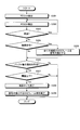
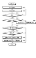
- FIG. 9 is a flowchart of blind decoding control in the mobile station according to the first embodiment.
- the transmission / reception unit 11 receives data including the PDCCH from the base station 2 and transmits the received data to the blind decoding control unit 112.
- the blind decoding control unit 112 decodes the PDCCH having the DCI format that is the decoding target of the received signal, and detects the PDCCH addressed to the own device (step S101).
- the PDCCH processing unit 111 receives the PDCCH detected by the blind decoding control unit 112 and notifies the PDSCH processing unit 121 of the PDSCH processing according to the received PDCCH.
- the PDSCH processing unit 121 receives and decodes the PDSCH from the transmission / reception unit 11 to detect and process the PDSCH (step S102).
- the HRAQ management unit 122 receives the PDSCH processing result from the PDSCH processing unit 121. Then, the HRAQ management unit 122 determines whether it is necessary to retransmit the received data (step S103). If retransmission is necessary (step S103: affirmative), the HRAQ management unit 122 issues an NACK transmission instruction to the uplink transmission unit 13, and returns to step S102.
- the blind decoding control unit 112 returns to “Msg0”, that is, normal blind decoding in which all DCI formats that may be received are to be decoded. It is determined whether or not a control signal as a trigger is received (step S104). When the control signal is received (step S104: affirmative), the blind decoding control unit 112 changes all the DCI formats that can be received to be the decoding target (step S105). On the other hand, when the control signal is not received (No at Step S104), the blind decoding control unit 112 proceeds to Step S106.
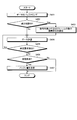
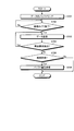
- FIG. 10 is a flowchart of blind decoding control in the base station according to the first embodiment.
- the upper station transmitting / receiving unit 21 receives downlink data transmitted from the upper station 3 to the mobile station 1. Then, the buffer control unit 211 obtains downlink data for the mobile station 1 from the upper station transmitting / receiving unit 21. Further, the buffer unit 221 receives the instruction from the buffer control unit 211, and stores the downlink data to the mobile station 1 (step S201).
- step S202 Whether the blind decoding control unit 212 has received a notification of the arrival of downlink data from the buffer control unit 211 and is performing reduction control to limit the DCI format that is currently subject to blind decoding of the mobile station 1 to a predetermined type It is determined whether or not (step S202).
- the blind decoding control unit 212 notifies the signal generation unit 214 of the arrival of downlink data.
- the signal generation unit 214 creates a PDCCH including Msg0 that is a trigger for returning the DCI format to be decoded to all types that can be received, and moves the created PDCCH via the transmission / reception unit 24. Transmit to the station 1 (step S203).
- the blind decoding control unit 212 proceeds to Step S204.
- the signal generation unit 214 acquires data to be transmitted from the data stored in the buffer unit 221 and creates data including PDCCH and PDSCH. Then, the signal generation unit 214 transmits the data generated via the transmission / reception unit 24 to the mobile station 1 (step S204).
- the HARQ management unit 222 detects a retransmission request by NACK from the mobile station 1 (step S205). If a retransmission request is detected (step S205: Yes), the HARQ management unit 222 instructs the signal generation unit 214 to retransmit the data that failed to be transmitted, and returns to step S204.
- the buffer control unit 211 acquires the amount of data stored in the buffer unit 221. Then, the buffer control unit 211 determines whether it is necessary to transmit a control signal triggered by a decrease in the type of DCI format targeted for decoding by the mobile station 1, depending on whether or not the buffer unit 221 is empty. (Step S206). When the control signal is necessary (step S206: Yes), the blind decoding control unit 212 instructs the signal generation unit 214 to notify the mobile station 1 that the buffer is empty.
- the signal generation unit 214 in response to the instruction from the blind decoding control unit 212, the signal generation unit 214 generates a signal by adding a flag for notifying that the buffer is empty to the PDCCH having a predetermined DCI format. Thereafter, the signal generation unit 214 transmits the generated signal to the mobile station 1 (step S207). On the other hand, when the control signal is unnecessary (No at Step S206), the base station 2 ends the blind decoding control process.
- the radio communication system is set as a decoding target in the mobile station from the time when the buffer in the base station becomes empty until downlink data arrives again in the Active Time section.
- the DCI format can be reduced. In other words, it is possible to reduce the number of times of decoding in PDCCH blind decoding during a period in which DRX is ON. Thereby, the mobile station can reduce power consumption. In addition, power can be reduced independently of the various timers that define Active Time. Therefore, for example, even when a plurality of applications are activated and cannot be put into the power saving mode, power consumption can be reduced in the mobile station.
- the decoding target when the decoding target is limited to a predetermined DCI format, the decoding target is the DCI format 0, 1A, 1C.
- the decoding target is the DCI format 0, 1A, 1C.
- which DCI format is targeted for decoding is not limited to this, and it is sufficient that at least a control signal and notification information that triggers the return of all DCI formats that can be received to the decoding target can be acquired.
- the return instruction can be acquired by transmitting Msg0 in the DCI format 1A as in the first embodiment.
- broadcast information can be acquired by the DCI format 1C.
- the restoration of blind decoding is not performed even if the PDCCH for uplink data transmission is received.
- the base station 2 knows that uplink data transmitted by the mobile station 1 is not generated. Therefore, the base station 2 measures the amount of data retained in the buffer of the mobile station 1 by BSR (Buffer Status Reporting) transmitted from the mobile station 1.
- BSR Buffer Status Reporting
- DCI format 0 As a result of receiving the BSR, when it can be determined that there is no uplink data amount of the mobile station 1, the DCI format 0 does not have to be a decoding target.
- DCI format 0 is preferably set as a decoding target. Therefore, when an SR (Scheduling Request) transmitted when the mobile station 1 arrives at uplink data, DCI format 0 is set as a decoding target using the reception as a trigger.
- the maximum number of times of decoding is the same as in the first embodiment, and the format to be detected is reduced from three types to two types. Can be lowered.
- zero allocation means that nothing is allocated to the PDSCH region. In this case, PDSCH is not attached to PDCCH. Then, the signal generation unit 214 transmits the PDCCH in which the PDSCH region is assigned to zero to the mobile station 1 via the transmission / reception unit 24.
- MAC CE MAC Control Element
- PDSCH PDSCH
- the present invention is not limited to this, and if the blind decoding is performed in a predetermined section, the function described above can be performed, and the power consumption can be reduced. There is an effect of reduction.
- the wireless communication system may notify that it will shift to energy saving (hereinafter referred to as “ES (Energy Saving) mode”).
- ES Energy Saving
- the mobile station and the base station according to the present embodiment are also represented by the block diagrams of FIGS. In the following, description of the configuration and operation of each part similar to those in the above-described embodiments and modifications will be omitted.
- the timing for transmitting the PDCCH to which the flag is added may be after the PDSCH that is the last data is transmitted, or may be transmitted by adding the flag to the accompanying PDCCH when transmitting the last PDSCH. .
- the blind decoding control unit 112 of the mobile station 1 receives the PDCCH to which a flag for notifying the transition from the base station 2 to the ES mode is added via the transmission / reception unit 11.
- the blind decoding control unit 112 receives the instruction to shift to the ES mode, and limits the DCI format to be decoded to a predetermined type, for example, only the DCI formats 0, 1A, and 1C in this embodiment. To do.
- FIG. 11 is a diagram for explaining the transition of the DCI format to be decoded in the wireless communication system according to the second embodiment.
- the mobile station 1 starts decoding and detecting PDCCH addressed to itself by targeting all PDCCHs having DCI formats that may be received. Thereafter, the base station 2 sequentially transmits data 502 to 504 including the PDCCH. The mobile station 1 sequentially receives and decodes the data 502 to 504 transmitted from the base station 2, detects the PDCCH addressed to itself, and processes each data according to the detected PDCCH.
- the base station 2 transmits a signal 505 in which a flag indicating the ES mode is added to the PDCCH having the DCI format 1 to the mobile station 1.
- the mobile station 1 receives the signal 505, decodes it, and detects the PDCCH addressed to itself. When the mobile station 1 confirms that the flag indicating the transition to the ES mode is added to the detected PDCCH, the mobile station 1 limits the DCI format to be decoded to 0, 1A, and 1C.
- the base station 2 transmits a signal 506 including the PDCCH of the DCI format 1A including Msg 0 to the mobile station 1.
- the mobile station 1 can detect a PDCCH by decoding a signal including Msg0.
- the mobile station 1 receives the signal 506 for notifying Msg0, the mobile station 1 returns the DCI format to be decoded to normal.
- the base station 2 transmits data 507 and 508 including the PDCCH to the mobile station 1.
- the mobile station 1 receives and decodes the data 507 and 508 transmitted from the base station 2, detects the PDCCH addressed to itself, and processes the data according to the detected PDCCH.
- the mobile station 1 performs decoding up to 60 times in the section 511 and the section 513 in the case of LTE-A.
- the mobile station 1 may perform decoding up to 28 times. For this reason, the number of times of decoding in blind decoding can be reduced and power consumption can be reduced as compared with the case where blind decoding in which decoding is performed a maximum of 60 times in all sections 500 of Active Time is continuously performed. it can.
- power can be reduced independently of the various timers that define Active Time. Therefore, for example, even when a plurality of applications are activated and cannot be put into the power saving mode, power consumption can be reduced in the mobile station.
- the radio communication system limits the DCI format to be decoded by notifying the transition to the ES mode.
- count of decoding in the blind decoding of PDCCH can be reduced in the area of Active Time, in other words, the area where DRX is ON.
- the process of a mobile station can be reduced and power consumption can be reduced.
- a flag for notifying the transition to the ES mode is added to the PDCCH in a predetermined DCI format.
- this MAC CE may be transmitted alone, or may be transmitted along with PDSCH which is the last data before the buffer becomes empty.
- the blind decoding control unit 112 receives the MAC CE. Then, the blind decoding control unit 112 acquires an instruction to shift from the received MAC CE to the ES mode. And the blind decoding control part 112 restrict
- the base station 2 can notify the mobile station 1 of the transition to the ES mode even using the MAC layer signal.
- the present invention is not limited to this, and if the blind decoding is performed in a predetermined section, the function described above can be performed, and the power consumption can be reduced. There is an effect of reduction.
- the radio communication system notifies the limitation of the DCI format to be decoded before the buffer of the base station 2 becomes empty, and the mobile station 1 receives the notification and then receives the notification when the timer expires.
- the DCI format is different from the above-described embodiments and modifications. Therefore, the following mainly describes the notification of restriction on the DCI format to be decoded and the restriction operation.
- the mobile station and the base station according to the present embodiment are also represented by the block diagrams of FIGS. In the following, description of the configuration and operation of each part similar to those in the above-described embodiments and modifications will be omitted.
- the buffer control unit 211 acquires a buffer amount (BSI: Buffer Status Indicator) of downlink data staying in the buffer unit 221 from the buffer unit 221. Then, the buffer control unit 211 outputs the acquired buffer amount to the blind decoding control unit 212.
- This buffer amount is represented by, for example, the number of remaining packets.
- the blind decoding control unit 212 acquires the buffer amount from the buffer control unit 211. Then, the blind decoding control unit 212 notifies the signal generation unit 214 of the buffer amount in a predetermined cycle. In the present embodiment, the blind decoding control unit 212 notifies, for example, once every 100 ms.
- the signal generation unit 214 notifies the mobile station of the timer value in advance using RRC.
- the signal generation unit 214 receives a buffer amount notification from the blind decoding control unit 212. Then, the signal generator 214 creates a signal for notifying the mobile station 1 of the buffer amount using the MAC CE. Then, the signal generation unit 214 transmits the created signal to the mobile station 1 via the transmission / reception unit 24.
- the signal generation unit 214 may transmit the MAC CE along with the PDSCH, or may transmit the MAC CE alone without accompanying the PDSCH.
- the blind decoding control unit 112 of the mobile station 1 stores in advance a buffer amount threshold value for starting a control timer for measuring the timing for limiting the DCI format to be decoded.
- the blind decoding control unit 112 stores the threshold value as 10 packets.
- the blind decoding control unit 112 receives the MAC CE including the buffer amount information via the transmission / reception unit 11. Thereafter, the blind decoding control unit 112 acquires buffer amount information from the received MAC CE. Further, the blind decoding control unit 112 determines whether or not the acquired buffer amount is 10 packets or less. When the acquired buffer amount becomes 10 packets or less, the blind decoding control unit 112 notifies the timer control unit 113 of activation of the control timer. Then, the blind decoding control unit 112 receives a notification of expiration of the control timer from the timer control unit 113. Then, the blind decoding control unit 112 limits the DCI format to be subjected to blind decoding to, for example, DCI formats 0, 1A, and 1C.
- the timer control unit 113 acquires a timer value in advance by RRC. Then, the timer control unit 113 receives the timer activation from the blind decoding control unit 112. Then, the timer control unit 113 starts the timer and counts up to the designated timer value. When the timer expires, the timer control unit 113 notifies the blind decoding control unit 112 that the timer has expired.
- control timer may be a DRX parameter such as drx-inactivity timer, or a new timer.
- drx-Inactivity Timer when a new timer is introduced as a control timer will be explained.
- the blind decoding control unit 112 does not have to perform decoding and detection of PDCCH at all, and when performing decoding and detection of PDCCH, only the PDCCH having a predetermined type of DCI format is subject to decoding.
- the blind decoding control unit 112 sets only the PDCCH having a predetermined type of DCI format as a decoding target.
- the blind decoding control unit 112 of the mobile station 1 uses the buffer amount to determine whether or not to limit the DCI format to be subjected to blind decoding. You may do it.
- the blind decoding control unit 212 of the base station 2 stores a buffer amount threshold for determining activation of the control timer in the mobile station 1. Then, the blind decoding control unit 212 notifies the signal generation unit 214 of a control timer activation command when the buffer amount acquired from the buffer control unit 211 is equal to or less than the threshold value.
- the signal generation unit 214 transmits a control timer activation command to the mobile station 1.
- the base station 2 can determine whether the DCI format to be decoded is limited. In this case, the blind decoding control unit 212 notifies the signal generation unit 214 aperiodically.
- FIG. 12 is a diagram for explaining the transition of the DCI format to be decoded in the wireless communication system according to the third embodiment.
- the mobile station 1 starts decoding and detecting PDCCH addressed to itself by targeting all PDCCHs having DCI formats that may be received. Thereafter, the base station 2 sequentially transmits data 602 to 604 including the PDCCH. The mobile station 1 sequentially receives and decodes the data 602 to 604 transmitted from the base station 2, detects the PDCCH addressed to itself, and processes each data according to the detected PDCCH.
- the buffer amount transmission period comes after the data 604, and the buffer amount at that time is 10 packets or less.
- the base station 2 transmits a signal 605 including a MAC CE that notifies the buffer amount to the mobile station 1.
- the mobile station 1 receives the signal 605 and acquires the buffer amount of the base station 2. In this case, since it is 10 packets or less, the mobile station 1 starts a control timer and measures a predetermined time 606. Then, at the timing 607 when the control timer expires, the mobile station 1 limits the DCI format to be decoded to 0, 1A, and 1C.
- the base station 2 transmits a signal 608 including a PDCCH of DCI format 1A including Msg 0 to the mobile station 1.
- the mobile station 1 can detect a PDCCH by decoding a signal including Msg0.
- the mobile station 1 receives the signal 608 notifying Msg0, the mobile station 1 returns the DCI format to be decoded to normal.
- the base station 2 transmits data 609 and 610 including the PDCCH to the mobile station 1.
- the mobile station 1 receives the data 609 and 610 transmitted from the base station 2, decodes it to detect the PDCCH addressed to itself, and processes the data according to the detected PDCCH.
- the mobile station 1 performs decoding up to 60 times in the sections 611 and 613 in the case of LTE-A.
- the mobile station 1 may perform decoding up to 28 times.
- the number of times of decoding in blind decoding can be reduced and power consumption can be reduced as compared with the case where blind decoding in which decoding is performed at maximum 60 times in all Active Time sections 600 is continuously performed. it can.
- power can be reduced independently of the various timers that define Active Time. Therefore, for example, even when a plurality of applications are activated and cannot be put into the power saving mode, power consumption can be reduced in the mobile station.
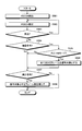
- FIG. 13 is a flowchart of blind decoding control in the mobile station according to the third embodiment.
- the transmission / reception unit 11 receives data including the PDCCH from the base station 2 and transmits the received data to the blind decoding control unit 112.
- the blind decoding control unit 112 decodes the PDCCH having the DCI format that is the decoding target of the received signal, and detects the PDCCH addressed to the own device (step S301).
- the PDCCH processing unit 111 receives the PDCCH detected by the blind decoding control unit 112 and notifies the PDSCH processing unit 121 of the PDSCH processing according to the received PDCCH.
- the PDSCH processing unit 121 receives and decodes the PDSCH from the transmission / reception unit 11 to detect and process the PDSCH (step S302).
- the HRAQ management unit 122 receives the PDSCH processing result from the PSCCH processing unit 111. Then, the HRAQ management unit 122 determines whether it is necessary to retransmit the received data (step S303). If retransmission is necessary (step S303: Yes), the HRQ management unit 122 instructs the uplink transmission unit 13 to transmit NACK, and the process returns to step S302.
- the blind decoding control unit 112 returns to “Msg0”, that is, normal blind decoding in which all DCI formats that can be received are to be decoded. It is determined whether a control signal as a trigger is received (step S304). When the control signal is received (step S304: affirmative), the blind decoding control unit 112 changes all the DCI formats that can be received to be the decoding target (step S305). On the other hand, when the control signal is not received (step S304: No), the blind decoding control unit 112 proceeds to step S306.
- the blind decoding control unit 112 determines whether or not a buffer amount notification has been received (step S306).
- the blind decoding control unit 112 determines whether or not the received buffer amount is equal to or less than the threshold (step S307).
- the blind decoding control unit 112 notifies the timer control unit 113 of activation of the control timer. And the timer control part 113 measures the time predetermined by the control timer, and expires the control timer (step S308).
- the blind decoding control unit 112 Upon receiving notification of the expiration of the control timer from the timer control unit 113, the blind decoding control unit 112 reduces the DCI format to be decoded to “0, 1A, 1C” which is a predetermined type of DCI format (step 1). S309).
- step S306 negative
- step S307 negative
- the mobile station 1 repeats the process of FIG. 13 for the period of Active Time.
- FIG. 14 is a flowchart of the blind decoding control in the base station according to the third embodiment.
- the upper station transmitting / receiving unit 21 receives downlink data transmitted from the upper station 3 to the mobile station 1. Then, the buffer control unit 211 obtains downlink data for the mobile station 1 from the upper station transmitting / receiving unit 21. Further, the buffer unit 221 receives the instruction from the buffer control unit 211, and stores the downlink data to the mobile station 1 (step S401).
- step S402 Whether the blind decoding control unit 212 has received a notification of the arrival of downlink data from the buffer control unit 211 and is performing reduction control to limit the DCI format that is currently subject to blind decoding of the mobile station 1 to a predetermined type It is determined whether or not (step S402).
- the blind decoding control unit 212 notifies the signal generation unit 214 of the arrival of downlink data.
- the signal generation unit 214 creates a PDCCH including Msg0 that triggers a return to return the DCI format to be decoded to all types that can be received, and moves the created PDCCH via the transmission / reception unit 24. Transmit to the station 1 (step S403).
- the blind decoding control unit 212 proceeds to Step S404.
- the signal generation unit 214 acquires data to be transmitted from the data stored in the buffer unit 221 and creates data including PDCCH and PDSCH. Then, the signal generation unit 214 transmits the data generated via the transmission / reception unit 24 to the mobile station 1 (step S404).
- the HARQ management unit 222 detects a retransmission request by NACK from the mobile station 1 (step S405). If a retransmission request is detected (step S405: affirmative), the HARQ management unit 222 instructs the signal generation unit 214 to retransmit data that has failed to be transmitted, and returns to step S404.
- the buffer control unit 211 determines whether or not the period for transmitting the buffer amount has arrived (Step S406).
- the buffer control unit 211 acquires the buffer amount accumulated in the buffer unit 221. Then, the buffer control unit 211 notifies the blind decoding control unit 212 of the buffer amount.
- the blind decoding control unit 212 instructs the signal generation unit 214 to notify the buffer amount.
- the signal generation unit 214 generates a MAC CE that notifies the buffer amount. Thereafter, the signal generation unit 214 transmits the generated MAC CE to the mobile station 1 (step S407).
- the base station 2 ends the blind decoding control process.
- the base station 2 repeats the process of FIG. 14 for the period of Active Time.
- the base station notifies the notification of the buffer amount of the downlink data that is retained, and the mobile station controls the control timer when the buffer amount becomes less than the threshold value.
- the control timer expires, the DCI format to be decoded is limited.
- the number of times of decoding in PDCCH blind decoding can be reduced in an Active Time section, in other words, in a section in which DRX is ON. And processing of a mobile station can be reduced and power consumption can be reduced.
- Modification 3-1 The modification 3-1 is different from the third embodiment in that a command for controlling the timer is transmitted to the base station instead of the buffer amount of the downlink data staying in the base station.
- the buffer control unit 211 acquires a buffer amount (BSI: Buffer Status Indicator) of downlink data staying in the buffer unit 221 from the buffer unit 221. Then, the buffer control unit 211 outputs the acquired buffer amount to the blind decoding control unit 212.
- BAI Buffer Status Indicator
- the blind decoding control unit 212 stores a buffer amount threshold for determining transmission of a timer control command. Then, the blind decoding control unit 212 notifies the signal generation unit 214 of transmission of a timer control command when the buffer amount acquired from the buffer control unit 211 is equal to or less than the threshold value.
- the signal generator 214 generates a MAC CE including a timer control command having a timer value. Then, the signal generation unit 214 transmits the generated MAC CE to the mobile station 1.
- the blind decoding control unit 112 of the mobile station 1 receives the MAC CE including the timer control command via the transmission / reception unit 11. Then, the blind decoding control unit 112 acquires the timer value from the received MAC CE, and notifies the timer control unit 113 of the activation of the control timer and the control timer value. When receiving the notification of the expiration of the control timer from the timer control unit 113, the blind decoding control unit 112 limits the DCI format to be decoded to, for example, the DCI formats 0, 1A, and 1C.
- the timer control unit 113 receives the timer activation and the timer value from the blind decoding control unit 112. Then, the timer control unit 113 starts the control timer and counts up to the designated control timer value. When the control timer expires, the timer control unit 113 notifies the blind decoding control unit 112 of the expiration of the control timer.
- the MAC CE that can carry a relatively large amount of information is used to notify the control instruction of the control timer. Is not limited to this.
- a method using PDCCH will be described.
- the signal generation unit 214 notifies the mobile station 1 of the value of the control timer in advance by RRC signaling. Then, the signal generation unit 214 generates a signal in which a flag that instructs activation of a timer, which is 1-bit information, is added to the PDCCH. Then, the signal generation unit 214 transmits the generated signal to the mobile station 1.
- the timer control unit 113 of the mobile station 1 is instructed by the blind decoding control unit 112 to start the control timer, the timer control unit 113 is notified by RRC signaling. Time is measured using the value of the control timer.
- Modification 3-2 In the third embodiment, the value of the control timer is described as a fixed value. However, in this modification, the value is changed according to the buffer amount, which is different from the third embodiment.
- the signal generation unit 214 has a table indicating the correspondence between the buffer amount and the value of the control timer.
- the correspondence between the buffer amount and the value of the control timer is set so that when the buffer amount is large, the value of the control timer is long, and when the buffer amount is small, the value of the control timer is short.
- the signal generation unit 214 acquires the value of the control timer corresponding to the buffer amount notified from the blind decoding control unit 212.
- the signal generation unit 214 creates a MAC CE including a control timer activation command and a control timer value.
- the signal generation unit 214 transmits the created MAC CE to the mobile station 1.
- the blind decoding control unit 112 does not have a threshold in this modification.
- the blind decoding control unit 112 receives the MAC CE including the control timer activation command and the control timer value via the transmission / reception unit 11.
- the blind decoding control unit 112 acquires a control timer start command and a control timer value from the received MAC CE. Then, the blind decoding control unit 112 notifies the timer control unit 113 of the start of the control timer together with the value of the control timer. When the blind decoding control unit 112 receives a notification that the control timer has expired from the timer control unit 113, the blind decoding control unit 112 limits the DCI format to be decoded to, for example, DCI formats 0, 1A, and 1C.
- the timer control unit 113 receives the start of the control timer and the value of the control timer from the blind decoding control unit 112. Then, the timer control unit 113 starts the timer and counts up to the designated control timer value. When the control timer expires, the timer control unit 113 notifies the blind decoding control unit 112 of the expiration of the control timer.
- the radio communication system according to the present embodiment is different from the above-described embodiments and modifications in that the base station 2 uses a control signal that triggers decoding of PDCCHs of all types of formats that may be received. Is. Therefore, the control signal will be mainly described below.
- the mobile station and the base station according to the present embodiment are also represented by the block diagrams of FIGS. In the following, description of the configuration and operation of each part similar to those in the above-described embodiments and modifications will be omitted.
- the PDCCH itself of DCI format 1A is used for notification of the arrival of downlink data, not Msg0 which is a trigger for starting random access.
- the DCI format 1A PDCCH corresponds to a control signal that triggers the restoration of blind decoding.
- the blind decoding control unit 112 sets the type of DCI format to be decoded as 0, 1A, 1C.
- the blind decoding control unit 112 performs decoding and detects the PDCCH addressed to its own device. And the blind decoding control part 112 returns to the state which makes all the types of DCI formats with a possibility of reception become decoding object by acquiring PDCCH of DCI format 1A.
- the blind decoding control unit 112 uses not only the DCI format 1A PDCCH instructing the implementation of random access but also the DCI format 1A PDCCH instructing the arrival of downlink data as a trigger for limiting the decoding target. Use.
- FIG. 15 is a diagram for explaining the transition of the DCI format to be decoded in the wireless communication system according to the fourth embodiment.
- the mobile station 1 starts decoding and detecting PDCCH addressed to itself by targeting all PDCCHs having a DCI format that may be received. Thereafter, the base station 2 sequentially transmits data 702 to 704 including the PDCCH. The mobile station 1 sequentially receives and decodes the data 702 to 704 transmitted from the base station 2, detects the PDCCH addressed to itself, and processes each data according to the detected PDCCH.
- the base station 2 transmits a signal 706 including the PDCCH in the DCI format 1A to the mobile station 1.
- the mobile station 1 can detect the PDCCH by decoding the received PDCCH of the DCI format 1A because the DCI format 1A is included in the decoding target.
- the mobile station 1 receives the signal 706 that is the PDCCH in the DCI format 1A
- the mobile station 1 returns to a state in which all types of DCI formats that can be received are decoded.
- the base station 2 transmits data 707 and 708 including the PDCCH to the mobile station 1.
- the mobile station 1 receives the data 707 and 708 transmitted from the base station 2, decodes it to detect the PDCCH addressed to itself, and processes the data according to the detected PDCCH.
- the mobile station 1 performs decoding up to 60 times in the section 711 and the section 713 in the case of LTE-A.
- the mobile station 1 may perform decoding up to 28 times. For this reason, the number of times of decoding in blind decoding can be reduced and power consumption can be reduced compared with the case where blind decoding in which decoding is performed a maximum of 60 times in all Active Time sections 700 is continued. it can.
- the wireless communication system uses the DCI format 1A PDCCH to return the mobile station to a state where decoding is possible for all types of PDCCHs that may be received. Let Thereby, highly versatile notification can be performed.
- Modification 4-1 In this modification, by using a PDCCH flag, MAC CE or PDSCH padding as a return command, an instruction to decode PDCCHs of all types of formats that can be received is notified. Is different.
- the mobile station 1 can receive all types of PDCCH that may be received. It does not immediately return to the state to be decrypted.
- a compact PDSCH can be transmitted by the DCI format 1A. For this reason, in this modification, when the buffer amount exceeds a predetermined value, a control signal that triggers the decoding of PDCCHs of all types of formats that may be received is notified. be able to.
- the buffer control unit 211 acquires the buffer amount from the buffer unit 221. Then, the buffer control unit 211 notifies the blind decoding control unit 212 of the acquired buffer amount.
- the blind decoding control unit 212 stores a buffer amount threshold value for determining whether or not to limit the DCI format to be decoded.
- the blind decoding control unit 212 receives the buffer amount from the buffer control unit 211 in a state where the DCI format to be decoded is limited in the mobile station 1, the blind decoding control unit 212 determines whether or not the received buffer amount exceeds the threshold value. judge.
- the blind decoding control unit 212 instructs the signal generation unit 214 to transmit data using the DCI format 1A PDCCH. In this case, if the buffer amount is equal to or smaller than the threshold, it is possible to schedule data transmission to the mobile station 1 using the PDCCH of the DCI format 1A PDCCH.
- the blind decoding control unit 212 instructs the signal generation unit 214 to transmit a signal in which a flag whose buffer amount is equal to or larger than the threshold value is added to the PDCCH. This flag is created by adding 1-bit information to the PDCCH.
- the signal generation unit 214 receives an instruction to transmit data using the PDCCH in the DCI format 1A from the blind decoding control unit 212. Then, the signal generation unit 214 acquires the amount of data that can be transmitted in the DCI format 1A from the data stored in the buffer unit 221. Then, the signal generation unit 214 transmits a signal including data acquired using the PDCCH in the DCI format 1A to the mobile station 1 via the transmission / reception unit 24.
- the signal generation unit 214 receives from the blind decoding control unit 212 an instruction to transmit a signal in which a flag having a buffer amount equal to or larger than a threshold is added to the PDCCH. Then, the signal generation unit 214 generates a signal obtained by adding a flag to the PDCCH of the DCI format 1A used for data transmission. Next, the signal generation unit 214 transmits the generated signal to the mobile station 1 via the transmission / reception unit 24.
- the blind decoding control unit 112 receives a signal including the PDCCH of the DCI format 1A without a flag from the base station 2 via the transmission / reception unit 11 in a state where the DCI format to be decoded is limited. In this case, since the DCI format 1A is a decoding target, the blind decoding control unit 112 can detect the PDCCH of the DCI format 1A addressed to the own apparatus. Then, the blind decoding control unit 112 transmits the detected PDCCH in the DCI format 1A to the PDCCH processing unit 111. In this case, the blind decoding control unit 112 does not return to a state where all types of DCI formats that may be received are targeted for decoding.
- the blind decoding control unit 112 receives the DCI format 1A PDCCH with the flag via the transmission / reception unit 11. Also in this case, since the DCI format 1A is a decoding target, the blind decoding control unit 112 can detect the PDCCH of the DCI format 1A addressed to the own apparatus. Then, the blind decoding control unit 112 confirms that a flag is added to the detected PDCCH. In this case, the blind decoding control unit 112 returns to a state in which all types of DCI formats that can be received are targeted for decoding. Further, the blind decoding control unit 112 transmits the detected PDCCH to the PDCCH processing unit 111.
- the flag is added to the PDCCH for notification, but as described above, it is also possible to use MAC CE or PDSCH padding.
- the blind decoding control unit 212 may cause the signal generation unit 214 to periodically notify the mobile station 1 of the buffer amount. In that case, in the mobile station 1, the blind decoding control unit 212 stores a threshold value, and when the buffer amount acquired from the received MAC CE is equal to or larger than the threshold value, all types of DCI formats that may be received. To the state to be decrypted.
- the blind decoding control unit 212 transmits a signal by adding padding to the PDSCH when the buffer amount is smaller than the threshold, and when the buffer amount is equal to or larger than the threshold, padding is performed on the PDSCH. Send the signal without adding.
- the blind decoding control unit 212 when no padding is detected from the received signal, the blind decoding control unit 212 returns to a state where all types of DCI formats that can be received are targeted for decoding.
- the radio communication system it is possible to continue limiting the types of DCI formats to be decoded until the buffer amount reaches a certain value. That is, compared with the first embodiment, the period for limiting the type of DCI format to be decoded can be extended, and the power consumption in the mobile station can be further reduced.
- Modification 4-2 In this modification, the DCI format to be decoded is limited to 0, 1A, and 1C, and PDCCH of all types of formats that can be received is decoded as a return command in addition to DCI format 1A. This is different from the first embodiment in that it is used for notification of a target instruction.
- TCP Transmission Control Protocol
- IP Internet Protocol
- RLC AM Radio Link Control Acknowledge Mode
- UDP User Data Protocol
- uplink data to the base station 2 is generated in the mobile station 1
- data generated using UDP is transmitted.
- RLC UM Radio Link Control Un-acknowledge Mode
- the mobile station 1 receives the DCI format 0 and transitions to the normal mode if it is the RLC AM mode.
- FIG. 16 is a flowchart of blind decoding control in a mobile station according to Modification 4-2.
- the transmission / reception unit 11 receives data including the PDCCH from the base station 2 and transmits the received data to the blind decoding control unit 112.
- the blind decoding control unit 112 decodes the PDCCH having the DCI format that is the decoding target of the received signal, and detects the PDCCH addressed to the own device (step S501).
- the PDCCH processing unit 111 receives the PDCCH detected by the blind decoding control unit 112 and notifies the PDSCH processing unit 121 of the PDSCH processing according to the received PDCCH.
- the PDSCH processing unit 121 receives and decodes the PDSCH from the transmission / reception unit 11 to detect and process the PDSCH (step S502).
- the HRAQ management unit 122 receives the PDSCH processing result from the PDCCH processing unit 111. Then, the HRAQ management unit 122 determines whether it is necessary to retransmit the received data (step S503). When retransmission is necessary (step S503: affirmative), the HRQ management unit 122 issues an NACK transmission instruction to the uplink transmission unit 13, and returns to step S502.
- the blind decoding control unit 112 determines whether “Msg0” or DCI format 0 PDCCH is received. That is, the blind decoding control unit 112 determines whether or not a control signal that triggers returning to normal blind decoding in which all DCI formats that can be received are to be decoded has been received (step S504). When the control signal is received (step S504: Yes), the blind decoding control unit 112 determines whether or not the RLC AM mode is set (step S505). When it is the RLC AM mode (step S505: Yes), the blind decoding control unit 112 changes all DCI formats that can be received to be a decoding target (step S506). On the other hand, if no return instruction has been received (step S504: negative) or not in the RLC AM mode (step S505: negative), the blind decoding control unit 112 proceeds to step S507.
- the mobile station 1 repeats the processing of FIG. 16 for the period of Active Time.
- the flow of blind decoding control in the base station 2 according to the modification 4-2 is the same as the flow shown in the flowchart of FIG.
- the signal is an RLC AM mode
- the signal is a return command that returns the DCI format to be decoded to all types that can be received. .
- the wireless communication system according to the present embodiment is different from the above-described embodiments and modifications in that the PDCCH of all types of formats that can be received is restored to a decoding target using a timer. . Therefore, in the following, a description will be mainly given of returning to a state where PDCCHs of all types of formats that can be received using a timer are subject to decoding.
- the mobile station and the base station according to the present embodiment are also represented by the block diagrams of FIGS. In the following, description of the configuration and operation of each part similar to those in the above-described embodiments and modifications will be omitted. In the present embodiment, a case will be described where the limit timer of the third embodiment is used as a trigger for limiting the DCI format to be decoded.
- the blind decoding control unit 112 notifies the timer control unit 113 of the start of the limited timer. In the present embodiment, it is assumed that the timer control unit 113 acquires the value of the limit timer in advance by RRC. The blind decoding control unit 112 receives the expiration of the control timer from the timer control unit 113. Then, the blind decoding control unit 112 limits the DCI format to be decoded to 0, 1, 1A. Thereafter, the blind decoding control unit 112 receives from the timer control unit 113 the expiration of the return timer that measures the time for returning to the state where all DCI formats that can be received are set as decoding targets. Then, the blind decoding control unit 112 returns to a state where all DCI formats that can be received are targeted for decoding.
- the timer control unit 113 holds in advance a return timer value that measures the time for returning to a state where all DCI formats that can be received are to be decoded.
- the timer control unit 113 receives a notification of activation of the limited timer from the blind decoding control unit 112. Then, the timer control unit 113 activates a limit timer and measures time. When the limit timer expires, the timer control unit 113 notifies the blind decoding control unit 112 that the limit timer has expired.
- the timer control unit 113 activates a return timer when the limit timer expires. And the timer control part 113 measures time to the value hold
- FIG. 17 is a diagram for explaining the transition of the DCI format to be decoded in the wireless communication system according to the fifth embodiment.
- the mobile station 1 starts decoding and detecting PDCCH addressed to itself by targeting all PDCCHs having a DCI format that may be received. Thereafter, the base station 2 sequentially transmits data 802 to 804 including the PDCCH. The mobile station 1 sequentially receives and decodes the data 802 to 804 transmitted from the base station 2, detects the PDCCH addressed to itself, and processes each data according to the detected PDCCH.
- the buffer amount transmission period comes after the data 804 and the buffer amount at that time is 10 packets or less.
- the base station 2 transmits a signal 805 including the MAC CE that notifies the buffer amount to the mobile station 1.
- the mobile station 1 receives the signal 805 and acquires the buffer amount of the base station 2. In this case, since it is 10 packets or less, the mobile station 1 starts a control timer and measures a predetermined time 806. Then, at the timing 807 when the control timer expires, the mobile station 1 limits the DCI format to be decoded to 0, 1A, and 1C.
- the mobile station 1 starts a return timer at a timing 807 when the control timer expires, and measures a predetermined time 808. Then, when the return timer expires, the mobile station 1 returns the decoding target DCI format to normal. Thereafter, the base station 2 transmits data 809 and 810 including the PDCCH to the mobile station 1. The mobile station 1 receives the data 809 and 810 transmitted from the base station 2, decodes it to detect the PDCCH addressed to itself, and processes the data according to the detected PDCCH.
- the mobile station 1 performs decoding up to 60 times in the sections 811 and 813 in the case of LTE-A.
- the mobile station 1 may perform decoding up to 28 times.
- the number of times of decoding in blind decoding can be reduced and power consumption can be reduced compared to the case where blind decoding in which decoding is performed a maximum of 60 times in all Active Time sections 800 is continued. it can.
- power can be reduced independently of the various timers that define Active Time. Therefore, for example, even when a plurality of applications are activated and cannot be put into the power saving mode, power consumption can be reduced in the mobile station.
- FIG. 18 is a flowchart of blind decoding control in the mobile station according to the fifth embodiment.
- the transmission / reception unit 11 receives data including the PDCCH from the base station 2 and transmits the received data to the blind decoding control unit 112.
- the blind decoding control unit 112 decodes the PDCCH having the DCI format that is the decoding target of the received signal, and detects the PDCCH addressed to the own apparatus (step S601).
- the PDCCH processing unit 111 receives the PDCCH detected by the blind decoding control unit 112 and notifies the PDSCH processing unit 121 of the PDSCH processing according to the received PDCCH.
- the PDSCH processing unit 121 receives and decodes the PDSCH from the transmission / reception unit 11 to detect and process the PDSCH (step S602).
- the HRAQ management unit 122 receives the PDSCH processing result from the PDSCH processing unit 111. Then, the HRAQ management unit 122 determines whether it is necessary to retransmit the received data (step S603). If retransmission is necessary (step S603: Yes), the HRQ management unit 122 instructs the uplink transmission unit 13 to transmit NACK, and the process returns to step S602.
- the blind decoding control unit 112 determines whether or not the return timer has expired (Step S604). When the return timer has expired (step S604: affirmative), the blind decoding control unit 112 changes all DCI formats that may be received to be subject to decoding (step S605). On the other hand, if the return timer has not expired (step S604: NO), the blind decoding control unit 112 proceeds to step S606.
- the blind decoding control unit 112 determines whether or not a buffer amount notification has been received (step S606).
- the blind decoding control unit 112 determines whether or not the received buffer amount is equal to or less than the threshold value (step S607).
- the blind decoding control unit 112 notifies the timer control unit 113 that the control timer is started. Then, the timer control unit 113 measures a time determined in advance by the control timer, expires the control timer, and starts a return timer (step S608).
- the blind decoding control unit 112 Upon receiving notification of the expiration of the control timer from the timer control unit 113, the blind decoding control unit 112 reduces the DCI format to be decoded to “0, 1A, 1C” which is a predetermined type of DCI format (step 1). S609).
- step S606 negative
- step S607 negative
- FIG. 19 is a flowchart of blind decoding control in the base station according to the fifth embodiment.
- the upper station transmitting / receiving unit 21 receives downlink data transmitted from the upper station 3 to the mobile station 1. Then, the buffer control unit 211 obtains downlink data for the mobile station 1 from the upper station transmitting / receiving unit 21. Further, the buffer unit 221 receives the instruction from the buffer control unit 211, and stores the downlink data to the mobile station 1 (step S701).
- the blind decoding control unit 212 determines whether or not the return timer of the mobile station 1 has expired (step S702). If the return timer has not expired (step S702: No), the blind decoding control unit 212 waits until the return timer expires. When the return timer has expired (step S702: affirmative), the signal generation unit 214 acquires data to be transmitted from the data stored in the buffer unit 221, and creates data including PDCCH and PDSCH. Then, the signal generation unit 214 transmits the data generated via the transmission / reception unit 24 to the mobile station 1 (step S703).
- the HARQ management unit 222 detects a retransmission request by NACK from the mobile station 1 (step S704). If a retransmission request is detected (step S704: affirmative), the HARQ management unit 222 instructs the signal generation unit 214 to retransmit data that has failed to be transmitted, and returns to step S703.
- step S704 determines whether or not a period for transmitting the buffer amount has arrived (step S705).
- step S705 Yes
- the buffer control unit 211 acquires the buffer amount accumulated in the buffer unit 221.
- the buffer control unit 211 instructs the signal generation unit 214 to notify the buffer amount.
- the signal generation unit 214 generates a MAC CE that notifies the buffer amount.
- the signal generation unit 214 transmits the generated MAC CE to the mobile station 1 (step S706).
- step S705 No
- the base station 2 ends the blind decoding control process.
- the blind decoding control unit 112 immediately cancels the Short DRX or Long DRX, and transitions to OnDuration. Thereafter, the blind decoding control unit 112 may return to a state in which all DCI formats that may be received are targeted for decoding, or if the downlink data has not arrived, You may continue the state to restrict
- the blind decoding control unit 112 does not transit to OnDuration, but waits for the return timer to expire and starts OnDuration.
- the blind decoding control unit 112 links the expiration of the return timer and the start position of OnDuration, and returns to the normal mode when downlink data arrives.
- the mobile station activates the return timer and measures the timing for all DCI formats that may be received autonomously as the decoding target. As a result, it is possible to return to a state where all DCI formats that can be received without waiting for a notification from the base station are to be decoded. For example, even if a notification from the base station does not reach the mobile station, Thus, it is possible to return to a state where all DCI formats that can be received are targeted for decoding.
- the radio communication system according to the present embodiment is different from the above-described embodiments and modifications in that not only DS but also SPS is implemented as a scheduler.
- the mobile station and the base station according to the present embodiment are also represented by the block diagrams of FIGS. In the following, description of the configuration and operation of each part similar to those in the above-described embodiments and modifications will be omitted.
- the blind decoding control unit 112 receives the SPS transmission timing from the timer control unit 113 in a state where the DCI format to be decoded is limited. Then, the blind decoding control unit 112 returns to a state where all DCI formats that can be received are targeted for decoding at the start position of the SPS transmission timing. Then, the blind decoding control unit 112 returns to the state where the DCI format to be decoded is limited at the end position of the SPS transmission timing.
- the timer control unit 113 receives RRC signaling including SPS transmission timing from the base station 2 via the transmission / reception unit 11. And the timer control part 113 acquires the transmission interval of SPS from the received RRC signaling. When the timer control unit 113 receives an activation command using the PDCCH, the timer control unit 113 notifies the blind decoding control unit 112 of the transmission timing of the SPS.
- the scheduling unit 23 in the base station 2 calculates SPS transmission timing. Then, the scheduling unit 23 notifies the signal generation unit 214 of the calculated SPS transmission timing.
- the signal generation unit 214 receives notification of SPS transmission timing from the scheduling unit 23. Then, the signal generation unit 214 generates RRC signaling including SPS transmission timing. Then, the signal generation unit 214 transmits the generated RRC signaling to the mobile station 1 via the transmission / reception unit 24. Furthermore, when actually starting SPS, an Activation command by PDCCH is transmitted, and SPS is started from the subframe.
- FIG. 20 is a diagram for explaining the transition of the DCI format to be decoded in the wireless communication system according to the first embodiment.
- the mobile station 1 starts decoding and detecting the PDCCH addressed to its own device for all PDCCHs having a DCI format that may be received from time 901. Thereafter, the base station 2 sequentially transmits data 902 to 904 including the PDCCH. The mobile station 1 sequentially receives and decodes the data 902 to 904 transmitted from the base station 2, detects the PDCCH addressed to itself, and processes each data according to the detected PDCCH.
- the mobile station 1 when the SPS transmission timing arrives, the mobile station 1 returns to a state in which all types of DCI formats that can be received are decoded.
- the hatched portion corresponds to the SPS transmission timing, and in this portion, the mobile station 1 has returned to the state of decoding all types of DCI formats that may be received.
- the mobile station 1 can receive the data 906 and 907 transmitted by the base station 2.
- the base station 2 transmits a signal 908 including a PDCCH of DCI format 1A including Msg 0 to the mobile station 1.
- the mobile station 1 When the mobile station 1 receives the signal 908 for notifying Msg0, the mobile station 1 returns to a state of decoding all types of DCI formats that may be received. Thereafter, the base station 2 transmits data 909 and 910 including the PDCCH to the mobile station 1. The mobile station 1 receives the data 909 and 910 transmitted from the base station 2, decodes it to detect the PDCCH addressed to itself, and processes the data according to the detected PDCCH.
- the mobile station 1 may perform decoding 28 times at maximum in the sections 911, 912, and 913. For this reason, the number of times of decoding in blind decoding can be reduced and power consumption can be reduced compared to the case where blind decoding in which decoding is performed a maximum of 60 times in all Active Time sections 900 is continued. it can.
- FIG. 21 is a flowchart of the blind decoding control when the mobile station according to the sixth embodiment receives the SPS.
- the timer control unit 113 receives RRC signaling including an SPS transmission interval and the like, and an activation command by PDCCH for actually starting communication. Then, the timer control unit 113 acquires information related to the SPS such as the transmission interval from the RRC signaling and the transmission timing from the activation command by the PDCCH, and sets the SPS (step S801).
- the blind decoding control unit 112 receives the notification from the timer control unit 113 and determines whether or not it is the SPS communication timing (step S802). In the case of the SPS communication timing (step S802: Yes), the blind decoding control unit 112 returns to a state where all DCI formats that can be received are targeted for decoding (step S803). On the other hand, if it is not the SPS communication timing (No at Step S802), the blind decoding control unit 112 proceeds to Step S804.
- the blind decoding control unit 112 detects the SPS data transmitted from the base station 2 (step S804). Then, the HARQ management unit 122 determines whether or not the received SPS data needs to be retransmitted (step S805). If retransmission of the received SPS data is necessary (step S805: Yes), the blind decoding control unit 112 returns to step S804.
- the blind decoding control unit 112 restricts the types of DIC formats to be decoded (Step S806).
- the wireless communication system can receive all types of DCI frames that can be received at the SPS transmission timing even when the DCI format to be decoded is limited. Return to the state to be decrypted. Thus, even when both SPS and DS are used in the scheduler, it is possible to receive both SPS and DS signals while reducing power consumption.
- FIG. 22 is a hardware configuration diagram of the mobile station.
- FIG. 23 is a hardware configuration diagram of the base station.
- the mobile station 1 includes a processor 1001, a ROM 1002, a main memory 1003, a storage 1004, a wireless communication unit 1005, a display unit 1006, an input unit 1007, a communication interface 1008, and an antenna 1009.
- ROM 1002, main memory 1003, storage 1004, wireless communication unit 1005, display unit 1006, input unit 1007, and communication interface 1008 are each connected to processor 1001 via bus 1010.
- the display unit 1006 is, for example, a liquid crystal screen.
- the input unit 1007 is, for example, a keypad. The operator of the mobile station 1 inputs a telephone number and the like using the display unit 1006 and the input unit 1007.
- the communication interface 1008 is, for example, a speaker and a microphone.
- One operator of the mobile station 1 performs operations such as voice transmission / reception using the communication interface 1008.
- the antenna 1009 is connected to the wireless communication unit 1005.
- the wireless communication unit 1005 and the processor 1001 realize, for example, the function of the transmission / reception unit 11 illustrated in FIG.
- the ROM 1002 stores a program for executing various processes performed by the control plane unit 110, the data plane unit 120, and the uplink transmission unit 13, for example. Then, the processor 1001 reads out various programs stored in the ROM 1002, generates them in the main memory 1003, and generates and executes processes for performing the respective processes.
- the processor 1001, the ROM 1002, the main memory 1003, and the storage 1004 realize the above-described functions by the control plane unit 110, the data plane unit 120, and the upstream transmission unit 13 illustrated in FIG.
- the base station 2 includes a processor 1101, a ROM 1102, a main memory 1103, a storage 1104, a wireless communication unit 1105, a display unit 1106, an input unit 1107, a communication interface 1108, and an antenna 1109.
- ROM 1102, main memory 1103, storage 1104, wireless communication unit 1105, display unit 1106, input unit 1107, and communication interface 1108 are each connected to the processor 1101 via a bus 1110.
- the display unit 1106 is, for example, a monitor.
- the input unit 1107 is, for example, a keyboard. The operator of the base station 2 uses the display unit 1106 and the input unit 1107 to input a telephone number and the like.
- the communication interface 1108 is, for example, an interface for performing communication with an upper station. Specifically, it is a network board or ADC (Analog Digital Converter).
- the communication interface 1108 and the processor 1101 implement the function of the higher-level station transmission / reception unit 21 shown in FIG. 2, for example.
- the antenna 1109 is connected to the wireless communication unit 1105.
- the wireless communication unit 1105 and the processor 1101 realize the function of the transmission / reception unit 24 illustrated in FIG. 2, for example.
- the storage 1104 is a storage device such as a hard disk.
- the storage 1104 and the processor 1101 implement the function of the buffer unit 221.
- the ROM 1102 stores programs for executing various processes performed by the control plane unit 210, the data plane unit 220, and the scheduling unit 23, for example. Then, the processor 1101 reads various programs stored in the ROM 1102, develops them in the main memory 1103, and generates and executes processes for performing each process.
- the processor 1101, the ROM 1102, the main memory 1103, and the storage 1104 realize the above-described functions by the control plane unit 210, the data plane unit 220, and the scheduling unit 23 illustrated in FIG.
Landscapes
- Engineering & Computer Science (AREA)
- Signal Processing (AREA)
- Computer Networks & Wireless Communication (AREA)
- Quality & Reliability (AREA)
- Mobile Radio Communication Systems (AREA)
Abstract
移動局(1)及び基地局を有する無線通信システムである。基地局は、移動局(1)のデータ量の計測結果を基に、移動局(1)に対して復号処理の変更の契機となる制御信号を含む信号を送信するブラインド復号制御部を備える。移動局(1)は、基地局から受信した制御信号を契機に、復号の対象とする信号のフォーマットを選択し、前記基地局から受信する信号のうち選択したフォーマットを有する信号に対して復号を実施して自装置宛の制御信号を検出するブラインド復号制御部(112)を備える。
Description
本発明は、無線通信システム、移動局、基地局及び無線通信システム制御方法に関する。
近年、セルラ型の移動通信は、UMTS(Universal Mobile Telecommunication System)からLTE(Long Term Evolution)に進化してきている。LTEでは、無線アクセス技術として、OFDM(Orthogonal Frequency Division Multiplexing)をベースとした方式が規定され、下りのピーク伝送レートは100Mb/s以上であり、上りのピーク伝送レートは50Mb/s以上である高速無線パケット通信が可能となる。さらに、国際標準化団体である3GPP(3rd Generation Partnership Project)では、更なる高速通信の実現に向けて、LTEをベースとした移動通信システムであるLTE-A(LTE-Advanced)の検討が始まっている。
また、LTE及びLTE-Aでは、移動局の省電力モードを実施する方法であるDRX(Discontinuous Reception)が用いられることがある。ここで、DRXについて具体的に説明する。移動局には、データ送受信を制御するL1信号であるPDCCH(Physical Downlink Data Channel)のモニタが必須である区間と必須でない区間が既定される。これらの区間は周期的に設定されDRXサイクルと呼ばれ、アプリケーション単位ではなく、移動局単位で一意に設定される。PDCCHのモニタが必須でない区間では、データ処理などの信号処理を行う必要が無いため、移動局は省電力モードに移行することができる。省電力モードでは、例えば、移動局はベースバンド部の信号処理などを停止する。DRXサイクルは通信開始時に、基地局が移動局に対してパラメータなどをL3信号であるRRC(Radio Resource Control)を使って通知することにより設定される。より具体的には、移動局は、制御信号であるRRCを受信し、RRCにより通知されたDRXパラメータに従ってDRXを設定する。DRXの開始はSFN(System Frame Number)の関数で規定される。その他のDRXの基本的なパラメータとしては、OnDurationTimerがある。このタイマが回っている区間はOnDurationと呼ばれ、この区間では移動局は省電力モードに移行することができない。そして、このタイマが回っていない区間、すなわちOnDuration以外の区間では、移動局は省電力モードに移行することができると規定されている。
さらに、LTE及びLTE-Aでは、データ受信のスケジューリング方法として、DS(Dynamic Scheduling)及びSPS(Semi-Persistent Scheduling)と呼ばれる2種類の方法が規定されている。DSは、上り及び下りの通信のいずれもPDCCHで利用している無線リソースが指定され、指定されたパラメータでデータであるPDSCH(Physical Downlink Shared Channel)を送信する。一方SPSは、通信を実際に実行する前から、所定の送信周期を有する所定の期間を予め通知しておく。そして、SPS通信を実施する場合、PDCCHによるActivationコマンドを基地局が送信し、どの無線リソースを継続使用するかを移動局に通知することにより通信が開始される。また、基地局は、PDCCHによるリリースコマンドを移動局に送信するなどして通信を停止する。
また、LTEやLTE-Aでは、PDCCHをモニタする場合、PDCCHのブラインド復号が行われる。基地局は、PDCCHをCCE(Control Channel Element)と呼ばれる無線リソースに割り当てて送信する。基地局は、移動局毎にPDCCHを生成し、制御情報が必要とするPDCCHに対応する数のCCEを割り当て、割り当てたCCEに対応する物理リソースに、DCIフォーマット(Downlink Control Information format)で定められる制御情報をマッピングして送信する。例えばセル境界付近などの伝搬路品質の劣悪な場所に位置する移動局に対しては、要求された受信品質を満たすために、MCS(Modulation and Coding Scheme)レベルが低いMCSを設定する必要がある。そこで、そのような場合には、基地局はより多くのCCE、例えば8つのCCEを占有したPDCCHを送信する。一方、セル中心付近などの伝搬路品質が良好な場所に位置する移動局に対しては、MCSレベルが高いMCSを設定しても要求される受信品質を満たすことができる。そのため、基地局はより少ないCCE、例えば1つのCCEを占有したPDCCHを送信する。さらに、物理リソースにマッピングする際に、制御情報の種別によって、セル固有の領域にマッピングするか、移動局固有の領域にマッピングするかが規定されている。この物理リソースにPDCCHがマッピングされる領域をサーチスペースと呼ぶ。
基地局は、各移動局向のPDCCHを1つのサブフレームに重畳して同時に送信する。ここで、1つの移動局向のPDCCHが占有するCCE数をアグリゲーションレベルと呼び、全てのPDCCHが占有するCCE数をアグリゲーションサイズと呼ぶ。基地局は、どの物理リソースにPDCCHがマッピングされているかの情報の通知を移動局に対して行なわない。そのため、移動局は、PDCCHを含むサブフレームの中に自局宛のPDCCHがあるか否かを検知する必要がある。この処理をブラインド復号と呼ぶ。具体的には、移動局は、サブフレームに設定された各サーチスペースにおける各アグリゲーションレベルに対してPDCCHの検出及び復号を試みることにより自局宛のPDCCHの検出を行う。このようなブラインド復号は、移動局のベースバンド部で実行されるため、移動局の電力を消費する。そこで、移動局における消費電力を低減するためには、ブラインド復号の回数を低減することが好ましい。
これに対して、近年、スマートフォンのように多数のアプリケーションが実行される移動局が増加している。また、トラフィックには、間欠的なトラフィックが各アプリケーションから発生することにより、見かけ上は連続したトラフィックとなるという特徴がある。そのため、多数のアプリケーションが間欠的にデータを発生させると、移動局としては、見かけ上連続したトラフィックとなる。このため、従来のDRXを用いた場合、OnDurationを長く設定する必要があるため、移動局は省電力モードに移行することができない。さらに、移動局は、PDCCHをモニタする区間としない区間は、単に規則的なパターンによって設定されるため、ブラインド復号にあたって、PDCCHをモニタする場合にはPDCCHの最大種類の数をモニタする。このため、従来の方法では、PDCCHのモニタが必須な区間では、常に最大数のPDCCHのモニタを継続し続けることになってしまう。
ここで、無線リソースを効率良く割り当てるための従来技術として、DSを用いた通信とSPSを用いた通信とを切り替えて通信を行う技術が提案されている。
3GPP TR 36.913, "Requirements for further advancements for Evolved Universal Terrestrial Radio Access (E-UTRA) (LTE-Advanced)", V9.0.0, Release 9, December 2009.
3GPP TR36.912, "Feasibility study for further advancements for E-UTRA (LTE-Advanced)", V9.3.0, Release 9, June 2010.
3GPP TS36.321, "Medium Access Control (MAC) protocol specification", V10.2.0, Release 10, June 2011.
3GPP TS36.133, "Requirements for support of radio resource management", V10.3.0, Release 10, June 2011.
3GPP TS36.213, "Physical layer procedures", V10.2.0, Release 10, June 2011.
3GPP TS36.300, "Evolved Universal Terrestrial Radio Access (E-UTRA) and Evolved Universal Terrestrial Radio Access Network (E-UTRAN)", V10.4.0, Release 10, June 2011.
しかしながら、DSを用いた通信とSPSを用いた通信とを切り替えて通信を行う従来技術を用いても、常にPDCCHをモニタする状況では、最大数のPDCCHのモニタを継続し続けることを回避することは困難である。そのため、従来の技術では、消費電力を低減することが困難である。
開示の技術は、上記に鑑みてなされたものであって、消費電力を効率的に低減する無線通信システム、移動局、基地局及び無線通信システム制御方法を提供することを目的とする。
本願の開示する無線通信システム、移動局、基地局及び無線通信システム制御方法は、一つの態様において、無線通信システムは、移動局及び基地局を有する。前記基地局は、前記移動局のデータ量の計測結果を基に、前記移動局に対して復号処理の変更の契機となる制御信号を含む信号を送信する制御部を備える。前記移動局は、前記基地局から受信した制御信号を契機に、復号の対象とする信号のフォーマットを選択し、前記基地局から受信する信号のうち選択したフォーマットを有する信号に対して復号を実施して自装置宛の制御信号を検出する復号部を備える。
本願の開示する無線通信システム、移動局、基地局及び無線通信システム制御方法の一つの態様によれば、消費電力を効率的に低減することができるという効果を奏する。
以下に、本願の開示する無線通信システム、移動局、基地局及び無線通信システム制御方法の実施例を図面に基づいて詳細に説明する。なお、以下の実施例により本願の開示する無線通信システム、移動局、基地局及び無線通信システム制御方法が限定されるものではない。
図1は、実施例1に係る移動局のブロック図である。また、図2は、実施例1に係る基地局のブロック図である。本実施例では、移動局1と基地局2とはDS(Dynamic Scheduling)を用いて通信を行うものとする。
図1に示すように、本実施例に係る移動局1は、送受信部11、制御部12及び上り送信部13を有している。さらに、制御部12は、制御プレーン部110及びデータプレーン部120を有している。そして、制御プレーン部110は、PDCCH(Physical Downlink Data Channel)処理部111、ブラインド復号制御部112及びタイマ制御部113を有している。また、データプレーン部120は、PDSCH(Physical Downlink Shared Channel)処理部121及びHARQ(Hybrid Automatic Repeat Request)管理部122を有している。
送受信部11は、後述する基地局2との間でアンテナを介して無線信号の送受信を行う。送受信部11は、DRXの設定条件を通知する制御信号であるL3信号であるRRC(Radio Resource Control)を基地局2から受信する。RRCは、DRXサイクルや起動するタイマの条件などが含まれている。そして、送受信部11は、受信したRRCをタイマ制御部113へ送信する。また、送受信部11は、基地局2からPDCCHやPDSCHを含む信号を受信する。そして、送受信部11は、受信した信号をブラインド復号制御部112及びPDSCH処理部121へ出力する。
さらに、送受信部11は、基地局2のバッファが空であることを示す信号を基地局2から受信する。本実施例では、送受信部11は、予め決められたいずれかのDCIフォーマットを有するPDCCHに付加された1ビットの情報であるフラグにより、バッファが空であることを示すBuffer Status Indicator(以下では、「BSI」と呼ぶ。)=0の通知を受ける。DCIフォーマットについては後で詳細に説明する。ここで、基地局2のバッファが空であることを示すフラグを付けるPDCCHのDICフォーマットはどのフォーマットを用いてもよい。例えば、本実施例では、後述するDCIフォーマットの中の、DCIフォーマット1、1A、2、2Aを用いる。そして、送受信部11は、BSI=0の情報を受信すると、その旨をブラインド復号制御部112へ出力する。
また、送受信部11は、下りデータの再到着の通知を基地局2から受信する。本実施例では、送受信部11は、DCIフォーマット1Aを使って送信される「Msg0」という制御信号を受信することで、下りデータの再到着の通知を受ける。ここで、Msg0は、基地局2が移動局1に対しランダムアクセスの実行を指示する信号である。本来、基地局2は、下りデータに対する移動局1からのACK(ACKnowledgement)/NACK(Negative ACKnowledgement)の受信のために移動局1の上り同期を確保させるように、移動局1にランダムアクセスを実施させることを目的としてMsg0を送信する。しかし、本実施例では、Msg0を、通常のPDCCHのモニタに切り替えるための制御信号として再利用している。この場合、移動局1の上り同期が既に確保できていれば、ランダムアクセスは実行しない。これに対して、移動局1の上り同期が確保できていなければ、ランダムアクセスを実行する。そして、送受信部11は、基地局2からMsg0を受信したことをブラインド復号制御部112へ通知する。
また、送受信部11は、NACK及びその他のデータを上り送信部13から受信する。そして、送受信部11は、上り送信部13から受信したNACK及びその他のデータを基地局2へ送信する。
タイマ制御部113は、RRCの入力を送受信部11から受ける。そして、タイマ制御部113は、DRXサイクル、並びに、SFN(System Frame Number)及び自装置の識別子を用いた関数からDRX開始のタイミングを求める。そして、タイマ制御部113は、DRXの開始のタイミングを、PDCCH処理部111及びブラインド復号制御部112に通知する。さらに、タイマ制御部113は、開始サブフレームからRRCで指定されたタイマを起動しそれぞれタイマでそれぞれに決められた時間の計測を行う。例えば、タイマは、図3に示すようなタイマを起動する。図3は、DRXにおけるタイマを説明するための図である。データ307~309及び311は、基地局2から送信されたPDCCHを含むデータを表している。そして、データ309は、受信に失敗したデータを表している。また、NACK310は、データ309の受信失敗を通知する否定応答である。さらに、データ311は、NACK310を受けて、基地局2がデータ309を再送したデータである。
図3に示すように、タイマ制御部113は、OnDuration Timer301、drx-Inactivity Timer302、HRAQ RTT Timer303、drx-Retransmission Timer304及びdrxShortCycle Timer305を起動する。OnDuration Timer301は、PDCCHの受信が必須となる区間であるOnDuration306の区間を計測する。すなわち、OnDuration Timer301が回っていない区間、言い換えればOnDuration306以外の区間であれば、PDCCHのモニタは必須で無いため、移動局1は、省電力モードに遷移することができる。
また、drx-Inactivity Timer302は新規データ到着(再送は除外)を通知するPDCCHを受信すると起動又は再起動される。例えば、基地局2からPDCCHを含むデータ307~309及び311を受信すると、drx-Inactivity Timer302は起動又は再起動する。したがって、drx-Inactivity Timer302が起動している場合もPDCCHのモニタは必須であり省電力モードに遷移することができない。すなわち、図3のようにdrx-Inactivity Timer302がOnDuration306の区間を超えて回っている場合、その間も省電力モードに遷移することができない。
HARQ RTT Timer303は新規のデータ又は再送のデータに関わらず起動又は再起動され、データの受信失敗を判定するHARQのRTT(Round Trip Time)を管理する。データ309の受信を失敗してからHARQ RTT Timer303が満了すると、移動局1は、NACK310を基地局2に送信する。
drx-Retransmission Timer304は、HARQ RTT Timer303が満了してもデータの受信に成功しなかった場合に起動され、タイマの起動中に再送が実施される。したがって、この区間中もPDCCHのモニタガ必須であり省電力モードに移行することはできない。
drx-Retransmission Timer304が満了すると、Short DRXが設定されている場合はShort DRXに遷移する。ここで、Short DRXとは、設定することが可能なオプションの区間である。このShort DRXの区間は、その区間にデータを受信した場合、drx-Inactivity Timer302を起動することにより、直ぐにPDCCHのモニタが必須である区間に遷移するように設定される区間であり、低遅延が実現できる。drxShortCycle Timer305は、rx-Retransmission Timer304が満了すると起動し、Short DRXの区間を管理する。drxShortCycle Timer305が満了するとLong DRXに直接遷移する。Long DRXは省電力モードに遷移することができる区間である。Short DRXが設定されていない場合は、Long DRXに直接遷移する。すなわち、タイマ制御部113によりOnDuration Timer301、drx-Inactivity Timer302及びdrx-Retransmission Timer304の満了が確認されると、制御部12は、省電力モードに移動局1を遷移させる。OnDuration Timer301、drx-Inactivity Timer302又はdrx-Retransmission Timer304のいずれかが起動している区間は、「Active Time」と呼ばれる。
タイマ制御部113は、HARQ RTT Timer303の満了、drx-Retransmission Timer304の開始をHARQ管理部122に通知する。
また、タイマ制御部113がOnDuration Timer301の満了及びdrx-Inactivity Timer302の満了をブラインド復号制御部112へ通知する。
ブラインド復号制御部112は、DRXの開始タイミングの入力をタイマ制御部113から受ける。そして、ブラインド復号制御部112は、受信したDRXの開始タイミングで受信の可能性がある全てのフォーマットのPDCCHに対してブラインド復号を行う。そして、ブラインド復号を行い、自装置宛のPDCCHを検出すると、ブラインド復号制御部112は、検出したPDCCHをPDCCH処理部111へ出力する。
また、ブラインド復号制御部112は、BSI=0の情報を受信した旨の通知を送受信部11から受ける。BSI=0の情報を受信した旨の通知を受けると、ブラインド復号制御部112は、予め決められたDCIフォーマットのPDCCHのみに復号対象を減少させてブラインド復号を行う。本実施例では、後述するDCIフォーマットのうち、0、1A、1Cのみを復号対象とする。この場合も、ブラインド復号制御部112は、ブラインド復号を行い自装置宛のPDCCHを検出すると、検出したPDCCHをPDCCH処理部111へ出力する。
どのDCIフォーマットを復号対象とするかをブラインド復号制御部112が把握する方法としては、通信開始前に基地局2からのRRCなどのシグナリングにより通知を受ける方法がある。また、基地局2からの通知を受けない方法としては、ブラインド復号制御部112において、復号対象とするDCIフォーマットを制限する場合には、「0、1A、1C」のみを復号対象とすると予め定義しておいてもよい。
ここで、図4~7を参照して、PDCCHのDCIフォーマット及びブラインド復号について説明する。図4は、PDCCHの候補数を説明するための図である。また、図5は、PDCCHのマッピング例である。また、図6は、各DCIフォーマットとサーチスペースの対応を表す図である。また、図7は、ブラインド復号の回数を説明するための図である。
図4のサーチスペース321は、ブラインド復号の対象となるサーチスペースを表している。すなわち、ブラインド復号制御部112は、サーチスペース321に示されたサーチスペースに対してブラインド復号を行う。また、アグリゲーションレベル322は、移動局1向けのPDCCHが占有するCCEの数を示している。例えば、アグリゲーションレベル322が2であれば、移動局1向けのPDCCHは2つのCCEを占有している。アグリゲーションサイズ323は、信号に含まれる全てのPDCCHが占有するCCEの数である。
例えば、図5のアグリゲーションサイズ330のように、サイズが12だとすると、アグリゲーションサイズ330の中には、アグリゲーションレベルが2のPDCCH331~336がマッピング可能である。すなわち、アグリゲーションサイズ330の中には、PDCCHの候補として、PDCCH331~336という6つの候補が選択できることになる。
しかし、基地局2は、サーチスペース、アグリゲーションレベル及びアグリゲーションサイズのいずれも移動局に対して通知しない。そのため、ブラインド復号制御部112は、各サーチスペースに対して、各アグリゲーションレベルでの各候補を順次選択して復号していくことを繰り返すことで、自装置宛のPDCCHを検出する。例えば、図5のようなアグリゲーションサイズ330であれば、その中の自装置宛のPDCCHの候補となるPDCCH331~336を順次選択して復号を繰り返していく。このように自装置宛のPDCCHである可能性がある候補に対して順次復号を繰り返していく処理をブラインド復号と呼ぶ。
そこで、図4に戻り、ブラインド復号制御部112が復号の対象とするPDCCHの候補の数を考えると、アグリゲーションサイズ323をアグリゲーションレベル322で除算することにより、PDCCH候補数324を求めることができる。例えば、アグリゲーションサイズ323が、図5のアグリゲーションサイズ330のように12個のCCEを有するとして、アグリゲーションレベルが2であれば、12÷2=6としてPDCCH候補数324を求めることができる。このようにして求めたものが、図4の各アグリゲーションレベル322及びアグリゲーションサイズ323の組に対応するPDCCH候補数324である。
図6では、行341にDCIフォーマット、行342に各DCIフォーマットに対応するペイロードサイズを記載している。さらに、行343及び行343は各DCIフォーマットがどのサーチスペースにマッピングされる可能性があるかを示している。図6に示すように、例えば、LTE-Aでは、DICフォーマットには、0、1、1A、1B、1C、1D、2、2A、3、3A、4の11種類のフォーマットがある。
DCIフォーマット0は、ペイロードサイズがAで、移動局固有及びセル固有のサーチスペースいずれにもマッピングされる。DCIフォーマット1は、ペイロードサイズがCで、移動局固有のサーチスペースのみにマッピングされる。DCIフォーマット1Aは、ペイロードサイズがAで、移動局固有及びセル固有のサーチスペースいずれにもマッピングされる。DCIフォーマット1Bは、ペイロードサイズがCで、移動局固有のサーチスペースのみにマッピングされる。DCIフォーマット1Cは、ペイロードサイズがBで、セル固有のサーチスペースのみにマッピングされる。DCIフォーマット1Dは、ペイロードサイズがCで、移動局固有のサーチスペースのみにマッピングされる。DCIフォーマット2は、ペイロードサイズがCで、移動局固有のサーチスペースのみにマッピングされる。DCIフォーマット2Aは、ペイロードサイズがCで、移動局固有のサーチスペースのみにマッピングされる。DCIフォーマット3は、ペイロードサイズがAで、セル固有のサーチスペースのみにマッピングされる。DCIフォーマット3Aは、ペイロードサイズがAで、セル固有のサーチスペースのみにマッピングされる。DCIフォーマット4は、ペイロードサイズがDで、移動局固有のサーチスペースのみにマッピングされる。
そして、各DCIフォーマットは、図6のようにペイロードサイズにより4種類(A~D)に分類される。ここで、ブラインド復号制御部112は、復号の対象としているフォーマット毎に、復号及び検出を行う必要がある。ただし、同じペイロードサイズであれば、1度の復号により自装置宛のどのフォーマットのPDCCHかは判定できるので、ブラインド復号制御部112は、同じペイロードサイズを有するフォーマットのPDCCHに対して、まとめて復号及び検出を行うことができる。図7では、各サーチスペースに対するペイロードサイズ毎にフォーマットをまとめて、そのフォーマット群に対するPDCCH候補の数を示している。行351がペイロードサイズを表している。そして、行352及び行353の各ペイロードサイズに対応する欄の上段が対応するフォーマットを表しており、下段がPDCCHの候補の数を表している。例えば、ペイロードサイズがAのグループで移動局固有のサーチスペースにマッピングされるのは、フォーマット0及び1Aであり、PDCCHの候補の数は16である。また、ペイロードサイズがAのグループでセル固有のサーチスペースにマッピングされるのは、フォーマット0、1A、3及び3Aであり、PDCCHの候補の数は6である。このように各ペイロードサイズにおける候補の数を足した合計は、移動局固有のサーチスペースにおいては、48となり、セル固有のサーチスペースにおいては、12となり、全てを足すと60となる。すなわち、ブラインド復号制御部112は、最大でも60回の復号を行なえば、全てのフォーマットのPDCCHの復号を完了することができる。ここではLTE-Aの場合を例に説明したが、LTEの場合には、上りMIMOが設定されていないため、DICフォーマット4の復号は試みる必要が無いので、最大44回の復号で全てのフォーマットのPDCCHの復号を完了することができる。
ブラインド復号制御部112は、復号対象とするフォーマットを減少させていない場合には、全てのフォーマットのPDCCHを復号対象とするため、LTE-Aでは最大60回、LTEでは最大44回の復号を行うことになる。
これに対して、復号対象とするフォーマットを減少させた場合、復号対象以外のフォーマットのPDCCHの復号は行わないので、ブラインド復号制御部112は、復号の回数を減らすことができる。本実施例では、復号対象とするフォーマットを減少させた場合の復号対象のフォーマットをDCIフォーマット0、1A及び1Cとする。ここで、DCIフォーマット0は、PUSCH(Physical Uplink Shared Channel)送信のための制御信号である。また、DCIフォーマット1Aは、コンパクトなPDSCH送信及びランダムアクセス開始を支持するための制御信号である。また、DCIフォーマット1Cは、報知情報などの非常にコンパクトなPDSCH送信のための制御信号である。ブラインド復号制御部112がPUSCH送信のための制御信号を受けるので、移動局1は、自装置からデータの送信を行うことができる。また、DCIフォーマット1Aを検出することで、ブラインド復号制御部112は、通常のPDCCHモニタに切り替えるためのMsg0を取得することができる。また、ブラインド復号制御部112がDCIフォーマット1Cを検出するので、移動局1は報知情報を取得することができる。このブラインド復号制御部112が、「復号部」の一例にあたる。
PDCCH処理部111は、自装置宛のPDCCHをブラインド復号制御部112から受ける。そして、PDCCH処理部111は、受信したPDCCHにしたがって処理を実施する。例えば、PDCCHによりPDSCHの受信が指示されていた場合、送受信部11からPDSCHを受信して処理を行うようにPDSCH処理部121に指示する。その他にも、上りデータの送信や報知情報に対する処理などを行う。このPDCCH処理部111が、「信号処理部」の一例にあたる。
PDSCH処理部121は、送受信部11からPDSCHを受信して処理を行う指示をPSCCH処理部111から受ける。そして、PDSCH処理部121は、送受信部11からPDSCHを受信する。そして、PDSCH処理部121は、受信したPDSCHを処理しMAC(Medium Access Control)などの上位レイヤにデータを回送する。また、PDSCH処理部121は、処理結果をHARQ管理部122へ通知する。
HARQ管理部122は、HARQ RTT Timer303の満了、drx-Retransmission Timer304の開始の通知をタイマ制御部113から受信する。また、HARQ管理部122は、PDSCH処理部121によるPDSCHの処理結果の通知を受ける。そして、HARQ管理部122は、HARQ RTT Timer303の満了しdrx-Retransmission Timer304の開始している間に、再送要求の実施命令を上り送信部13へ通知する。
また、制御部12は、PDSCH処理部121により処理されたデータをMAC、RLC、PDCPなどの各レイヤにおいて処理を実施し、ユーザにデータを提供する。さらに、制御部12は、ユーザから入力された音声データなどに対して各レイヤで処理を実施し、処理したデータを上り送信部13へ送信する。
上り送信部13は、HARQ管理部122から再送要求の実施命令を受信して、NACKを生成し、送受信部11を介して基地局2へ生成したNACKを送信する。また、上り送信部13は、制御部12で処理されたユーザから入力されたデータを受信すると、そのデータを送受信部11を介して基地局2へ送信する。
また、図2に示すように、本実施例に係る基地局2は、上位局送受信部21、制御部22、スケジューリング部23及び送受信部24を有している。さらに、制御部22は、制御プレーン部210及びデータプレーン部220を有している。そして、制御プレーン部210は、バッファ制御部211、ブラインド復号制御部212、タイマ制御部213及び信号生成部214を有している。また、基地局2は、ネットワークを介して上位局3と接続されている。
上位局送受信部21は、上位局3との間でネットワークを介してデータの送受信を行う。上位局送受信部21は、上位局3から受信したデータをバッファ制御部211へ出力する。また、上位局送受信部21は、信号生成部214からデータを受信する。そして、上位局送受信部21は、受信したデータを上位局3へ送信する。
バッファ制御部211は、上位局送受信部21からデータの入力を受ける。そして、バッファ制御部211は、バッファ部221に対してデータの格納命令をデータと共に出力する。
また、バッファ制御部211は、バッファ部221に蓄積されているデータの量を計測する。そして、バッファ制御部211は、バッファ部221が空か否かを判定する。バッファ制御部211は、バッファ部221が空になったと判定した場合、バッファ部221が空になったことをブラインド復号制御部212に通知する。また、バッファ制御部211は、バッファ部221が空の状態で、上位局送受信部21からデータの入力を受けた場合、下りデータの再到着をブラインド復号制御部212に通知する。このバッファ制御部211が、「データ量計測部」の一例にあたる。以上の説明は、下り通信の場合であるが、バッファ部221は、上り通信の場合にも使用される。つまり、バッファ部221は、移動局1から送信されるBSR(Buffer Status Reporting)を解析し、移動局1のバッファに滞留しているデータ量も計測する。
ブラインド復号制御部212は、バッファ部221が空になった通知をバッファ制御部211から受信する。そして、ブラインド復号制御部212は、バッファが空になったことを送信するように信号生成部214に指示する。この指示を出すことで、ブラインド復号制御部212は、移動局1が復号対象とするDCIフォーマットを制限していることを把握できる。これにより、基地局2は、ブラインド復号制御部212に移動局1の復号対象としているDCIフォーマットを確認し、それ以外のDICフォーマットを有するPDCCHを送信する。
また、ブラインド復号制御部212は、下りデータの再到着をバッファ制御部211から受信する。そして、ブラインド復号制御部212は、下りデータの再到着を送信するように信号生成部214に指示する。この指示を出すことで、ブラインド復号制御部212は、移動局1が受信の可能性のある全ての種類のDCIフォーマットを復号対象としていることを把握できる。このブラインド復号制御部212が、「制御部」の一例にあたる。
タイマ制御部213は、移動局1との間で行う通信のDRXサイクル及びデータの送信周期などをスケジューリング部23から受信する。そして、タイマ制御部213は、データの送信を行うタイミングをスケジューリング部23に通知する。またタイマ制御部213は、DRXサイクルのタイミングをスケジューリング部23に通知する。
信号生成部214は、移動局1との間で行う通信のDRXサイクルをスケジューリング部23から受信する。そして、信号生成部214は、DRXサイクルを含むRRCシグナリングを生成する。そして、信号生成部214は、生成したRRCシグナリングを送受信部24へ出力する。
また、信号生成部214は、移動局1を制御するための制御信号であるPDCCHを生成する。また、データ送信を行う場合、信号生成部214は、バッファ部221から送信データを取得し、PDSCHを生成する。信号生成部214は、PDCCHを送受信部24へ出力する。また、データの送信を行う場合は、信号生成部214は、生成したPDCCHにPDSCHを付随させて送受信部24へ出力する。
また、信号生成部214は、再送要求をHARQ管理部222から受ける。そして、信号生成部214は、再送要求を受けたデータを再度生成する。その後、信号生成部214は、生成した信号を送受信部24へ出力する。
さらに、信号生成部214は、バッファが空になったことを送信する指示をブラインド復号制御部212から受信する。そして、信号生成部214は、予め決められたDCIフォーマットを有するPDCCHにバッファが空になったことを示すフラグを付加させて信号を生成する。そして、信号生成部214は、生成したPDCCHにフラグを付加した信号を送受信部24へ出力する。ここで、フラグを付加して送信するPDCCHは、バッファ部221が空になる前の最後のPDSCHを送信した後に通知用のPDCCHを用いてもよいし、最後のPDSCHを送信する際に付随するPDCCHを用いてもよい。
また、信号生成部214は、下りデータの再到着の通知を送信する指示をブラインド復号制御部212から受信する。そして、信号生成部214は、Msg0という制御信号を送信するDCIフォーマット1AのPDCCHを生成し送受信部24へ出力する。ここで、本実施例では、DCIフォーマット1Aを用いてMsg0を送信することで、下りデータの再到着を通知しているが、通知に用いる信号はこれに限らない。この信号生成部214が、「信号送信部」の一例にあたる。
バッファ部221は、データと共にデータの格納命令の入力をバッファ制御部211から受ける。そして、バッファ部221は、受信したデータを格納し蓄積していく。また、バッファ部221に蓄積されたデータは、信号生成部214により取得されることで減少していく。
HARQ管理部222は、移動局1から送信されたNACKの入力を送受信部24から受ける。そして、HARQ管理部222は、NACKを受けた直前の送信データの再送要求を信号生成部214に通知する。
スケジューリング部23は、無線伝送のスケジューリングのアルゴリズムを記憶している。そして、スケジューリング部23は、記憶しているアルゴリズムを用いて移動局1に対するDRXサイクル及びデータの送信周期などを求める。そして、スケジューリング部23は、求めたDRXサイクル及びデータの送信周期などをタイマ制御部213へ送信する。また、スケジューリング部23は、DRXサイクルを信号生成部214へ通知する。
そして、スケジューリング部23は、DRXサイクルのタイミングを受けて、PDCCHを含む信号の送信の開始及び終了を送受信部24に指示する。
送受信部24は、アンテナを介して移動局1との間で無線信号の送受信を行う。送受信部24は、信号生成部214から受信したRRCシグナリングを移動局1へ送信する。また、送受信部24は、PDCCHを含む信号の送信の開始をスケジューリング部23から受ける。そして、送受信部24は、PDCCHを含む信号の入力を信号生成部214から受ける。そして、スケジューリング部23が指定したタイミングでPDCCHを含む信号を移動局1へ送信する。
また、送受信部24は、移動局1からデータを受信する。そして、送受信部24は、受信したデータを信号生成部214へ出力する。また、送受信部24は、アンテナを介して移動局1からNACKを受信する。この場合、送受信部24は、受信したNACKをHARQ管理部222へ出力する。
次に、図8を参照して、移動局における復号対象のDCIフォーマットの遷移について説明する。図8は、実施例1に係る無線通信システムにおける復号対象のDCIフォーマットの遷移について説明するための図である。図8は、紙面に向かって右にいくに従い時間の経過を表している。また、図8における区間400は、Active Timeを表している。
時刻401が、タイマ制御部113がSFN及び自装置の識別子などの共通情報の関数を用いて算出したDRX開始のタイミングである。時刻401から移動局1は受信の可能性のある全てのDCIフォーマットを有するPDCCHを対象として復号及び自装置宛のPDCCHの検出を開始する。例えば、UL MIMOが設定されていない場合、移動局1は、DCIフォーマット4を受信する可能性はないので、UL MIMOに関するDCIフォーマットのブラインド復号は実施しなくてもよい。その後、基地局2は、PDCCHを含むデータ402~404を順次送信する。移動局1は、基地局2から送信されたデータ402~404を順次受信し、復号して自装置宛のPDCCHを検出し、検出したPDCCHに従い各データを処理する。
ここで、データ404の送信によって基地局2のバッファが空になった場合で説明する。また、BSI=0を通知する予め決められたDCIフォーマットとしてDCIフォーマット1を用いる場合で説明する。基地局2は、DCIフォーマット1を有するPDCCHにBSI=0を示すフラグを付加させた信号405を移動局1に送信する。
移動局1は、信号405を受信した後、復号して自装置宛のPDCCHを検出する。そして、移動局1は、検出したPDCCHにBSI=0を示すフラグが付加されていることを確認すると、復号対象とするDCIフォーマットを0、1A、1Cに制限する。
その後、基地局2は、上位局3から移動局1に対して送信するデータを受信すると、Msg0を含むDCIフォーマット1AのPDCCHを含む信号406を移動局1に送信する。
移動局1は、DCIフォーマット1Aが復号対象に含まれているので、Msg0を含む信号を復号してPDCCHを検出することができる。そして、移動局1は、Msg0を通知する信号406を受信すると、受信の可能性がある全ての種類のDCIフォーマットを復号する状態に復帰する。その後、基地局2は、PDCCHを含むデータ407及び408を移動局1に送信する。移動局1は、基地局2から送信されたデータ407及び408を受信し、復号して自装置宛のPDCCHを検出し、検出したPDCCHに従いデータを処理する。
以上のことから、移動局1は、LTE-Aの場合では、区間411及び区間413では、最大60回の復号を行う。一方、区間412では、移動局1は、最大28回の復号を行えばよいことになる。このため、Active Timeの区間400の全てにおいて最大60回の復号を行うブラインド復号を継続して行った場合に比べて、ブラインド復号における復号の回数を減らすことができ、消費電力を低減することができる。また、Active Timeを規定する各種タイマとは独立して電力の削減を行うことができる。そのため、例えば、複数のアプリケーションが起動しており省電力モードに繊維できない場合でも、移動局において消費電力を低減することができる。
次に、図9を参照して、本実施例に係る移動局におけるブラインド復号制御の流れについて説明する。図9は、実施例1に係る移動局におけるブラインド復号制御のフローチャートである。
送受信部11は、PDCCHを含むデータを基地局2から受信し、受信したデータをブラインド復号制御部112へ送信する。ブラインド復号制御部112は、受信した信号の復号対象としているDCIフォーマットを有するPDCCHの復号を行い自装置宛のPDCCHを検出する(ステップS101)。
PDCCH処理部111は、ブラインド復号制御部112により検出されたPDCCHを受信し、受信したPDCCHに従いPDSCHの処理をPDSCH処理部121に通知する。PDSCH処理部121は、送受信部11からPDSCHを受信して復号を行なってPDSCHを検出し処理する(ステップS102)。
HRAQ管理部122は、PDSCH処理部121からPDSCHの処理結果を受信する。そして、HRAQ管理部122は、受信データの再送が必要か否かを判定する(ステップS103)。再送が必要な場合(ステップS103:肯定)、HRAQ管理部122は、上り送信部13に対してNACK送信の指示を出し、ステップS102に戻る。
これに対して、再送が不要な場合(ステップS103:否定)、ブラインド復号制御部112は、「Msg0」、すなわち受信の可能性がある全てのDCIフォーマットを復号対象とする通常のブラインド復号に戻る契機となる制御信号を受信しているか否かを判定する(ステップS104)。制御信号を受信している場合(ステップS104:肯定)、ブラインド復号制御部112は、受信の可能性のある全てのDCIフォーマットを復号対象とするように変更する(ステップS105)。これに対して、制御信号を受信していない場合(ステップS104:否定)、ブラインド復号制御部112は、ステップS106へ進む。
次に、ブラインド復号制御部112は、BSI=0、すなわち、予め決められた種類のDCIフォーマットのみを復号対象とする、復号対象のDCIフォーマットの減少の契機となる制御信号を受信したか否かを判定する(ステップS106)。制御信号を受信した場合(ステップS106:肯定)、ブラインド復号制御部112は、復号対象とするDCIフォーマットを予め決められた種類のDCIフォーマットである「0、1A、1C」に減らす(ステップS107)。これに対して、制御信号を受信していない場合(ステップS106:否定)、移動局1は、ブラインド復号制御の処理を終了する。
ここで、図9では、1回のブラインド復号制御の流れについて説明したが、移動局1は、図9の処理をActive Timeの期間繰り返す。
次に、図10を参照して、本実施例に係る基地局2におけるブラインド復号制御の流れについて説明する。図10は、実施例1に係る基地局におけるブラインド復号制御のフローチャートである。
上位局送受信部21は、上位局3から移動局1へ送信する下りデータを受信する。そして、バッファ制御部211は、移動局1への下りデータを上位局送受信部21から取得する。さらに、バッファ部221は、バッファ制御部211からの指示を受けて、移動局1への下りデータを格納する(ステップS201)。
ブラインド復号制御部212は、バッファ制御部211から下りデータの到着の通知を受けて、現在移動局1のブラインド復号の対象とするDCIフォーマットを予め決められた種類に限定する減少制御を行っているか否かを判定する(ステップS202)。減少制御中の場合(ステップS202:肯定)、ブラインド復号制御部212は、下りデータの到着を信号生成部214に通知する。そして、信号生成部214は、復号対象とするDCIフォーマットを受信の可能性のある全ての種類に戻す復帰の契機であるMsg0を含むPDCCHを作成し、送受信部24を介して作成したPDCCHを移動局1に送信する(ステップS203)。これに対して減少制御中で無い場合(ステップS202:否定)、ブラインド復号制御部212は、ステップS204に進む。
次に、信号生成部214は、バッファ部221に蓄積されたデータから送信するデータを取得し、PDCCH及びPDSCHを含むデータを作成する。そして、信号生成部214は、送受信部24を介して生成したデータを移動局1へ送信する(ステップS204)。
HARQ管理部222は、移動局1からのNACKにより再送要求の検出を行う(ステップS205)。再送要求が検出された場合(ステップS205:肯定)、HARQ管理部222は、信号生成部214に送信が失敗したデータの再送を指示しステップS204に戻る。
これに対して、再送要求が検出されない場合(ステップS205:否定)、バッファ制御部211は、バッファ部221に蓄積されたデータ量を取得する。そして、バッファ制御部211は、バッファ部221が空になっているか否かにより、移動局1が復号対象とするDCIフォーマットの種類の減少が契機される制御信号の送信が必要な否かを判定する(ステップS206)。制御信号が必要な場合(ステップS206:肯定)、ブラインド復号制御部212は、バッファが空であることを移動局1に通知するよう信号生成部214に指示する。そして、信号生成部214は、ブラインド復号制御部212からの指示を受けて、予め決められたDCIフォーマットを有するPDCCHにバッファが空であることを通知するフラグを付加して信号を生成する。その後、信号生成部214は、生成した信号を移動局1に送信する(ステップS207)。これに対して、制御信号が不要な場合(ステップS206:否定)、基地局2は、ブラインド復号制御の処理を終了する。
ここで、図10では、1回のブラインド復号制御の流れについて説明したが、基地局2は、図10の処理をActive Timeの期間繰り返す。
以上に説明したように、本実施例に係る無線通信システムは、Active Timeの区間において、基地局におけるバッファが空になってから再度下りデータが到来するまでの間、移動局において復号対象とするDCIフォーマットを減らすことができる。いかえれば、DRXがONの区間中においてPDCCHのブラインド復号における復号回数を減少させることができる。これにより、移動局は、消費電力を低減することができる。また、Active Timeを規定する各種タイマとは独立して電力の削減を行うことができる。そのため、例えば、複数のアプリケーションが起動しており省電力モードに繊維できない場合でも、移動局において消費電力を低減することができる。
(変形例1-1)
実施例1では、予め決められたDCIフォーマットに復号対象を制限する場合に、DCIフォーマット0、1A、1C復号対象とした。しかし、どのDCIフォーマットを復号対象とするかはこれに限らず、少なくとも、受信の可能性のある全てのDCIフォーマットを復号対象に戻す契機となる制御信号及び報知情報を取得できればよい。
実施例1では、予め決められたDCIフォーマットに復号対象を制限する場合に、DCIフォーマット0、1A、1C復号対象とした。しかし、どのDCIフォーマットを復号対象とするかはこれに限らず、少なくとも、受信の可能性のある全てのDCIフォーマットを復号対象に戻す契機となる制御信号及び報知情報を取得できればよい。
そこで、例えば、復号対象とするDCIフォーマットとして1A及び1CのDCIフォーマットのみとしてもよい。この場合、実施例1と同様に、DCIフォーマット1AによりMsg0を送信することで、復帰命令を取得できる。また、DCIフォーマット1Cにより報知情報を取得できる。この場合、実施例1と異なり、上りデータ送信のためのPDCCHを受信してもブラインド復号の復帰は実施しないことになる。DCIフォーマットとして0をモニタしない場合、基地局2は、移動局1が送信する上りデータが発生していないことを把握していることが好ましい。そのため、基地局2は、移動局1から送信されるBSR(Buffer Status Reporting)によって、移動局1のバッファに滞留しているデータ量を計測する。BSRを受信した結果、移動局1の上りデータ量がないと判定できる場合、DCIフォーマット0を復号対象としなくてもよい。一方、移動局1に上りデータが到着した場合、DCIフォーマット0を復号対象とすることが好ましい。そのため、移動局1の上りデータ到着時に送信されるSR(Scheduling Request)を受信すると、受信をトリガとして、DCIフォーマット0を復号対象とする。
1A及び1CのDCIフォーマットを有するPDCCHのみを復号対象とした場合、復号の最大回数が実施例1と同じであり、さらに、検出すべきフォーマットが3種類から2種類に減少するため、後検出率を低くすることができる。
また、実施例1では、BSI=0を通知する方法として、所定のDCIフォーマットのPDCCHにフラグを付加した。ただし、BSI=0を通知する方法は、移動局1がBSI=0であることを把握できればどのような方法であっても良い。以下の変形例1-2~1-4で、他の方法の例として、本変形例におけるBSI=0を通知する方法を説明する。
(変形例1-2)
信号生成部214は、BSI=0の通知をブラインド復号制御部212から受けると、PDCCHにPDSCH領域のゼロ割り当てを規定して信号を作成する。ここで、ゼロ割り当てとは、PDSCH領域に何も割り当てないことを指す。このケースでは、PDCCHに、PDSCHは付随しない。そして、信号生成部214は、PDSCH領域をゼロ割り当てとしたPDCCHを送受信部24を介して移動局1へ送信する。
信号生成部214は、BSI=0の通知をブラインド復号制御部212から受けると、PDCCHにPDSCH領域のゼロ割り当てを規定して信号を作成する。ここで、ゼロ割り当てとは、PDSCH領域に何も割り当てないことを指す。このケースでは、PDCCHに、PDSCHは付随しない。そして、信号生成部214は、PDSCH領域をゼロ割り当てとしたPDCCHを送受信部24を介して移動局1へ送信する。
ブラインド復号制御部112は、PDSCHをゼロ割り当てとしたPDCCHを受信する。通常は、PDSCHの割り当ては有限であるが、ゼロ割り当てを規定することにより、ブラインド復号制御部112は、PDSCHをゼロ割り当てとしたPDCCHを受信することで、基地局2においてBSI=0であるとみなす。
このように、PDSCHのゼロ割り当てを規定することで、基地局2は、BSI=0を移動局1に通知することができる。
(変形例1-3)
信号生成部214は、BSI=0の通知をブラインド復号制御部212から受けると、MACレイヤの制御信号であるMAC CE(MAC Control Element)を用いてBSI=0を移動局1に通知する信号を作成する。ここで、このMAC CEは、単独で送信しても良いし、バッファが空になる前の最後のデータであるPDSCHに付随させて送信しても良い。
信号生成部214は、BSI=0の通知をブラインド復号制御部212から受けると、MACレイヤの制御信号であるMAC CE(MAC Control Element)を用いてBSI=0を移動局1に通知する信号を作成する。ここで、このMAC CEは、単独で送信しても良いし、バッファが空になる前の最後のデータであるPDSCHに付随させて送信しても良い。
ブラインド復号制御部112は、MAC CEを受信する。そして、ブラインド復号制御部112は、MAC CEを受信したことで基地局2においてBSI=0であるとみなす。
このように、MACレイヤの信号を用いても、基地局2は、BSI=0を移動局1に通知することができる。
(変形例1-4)
信号生成部214は、BSI=0の通知をブラインド復号制御部212から受けると、バッファが空になる前の最後のデータであるPDSCHに余剰データであるパディングを付随させて送付する。
信号生成部214は、BSI=0の通知をブラインド復号制御部212から受けると、バッファが空になる前の最後のデータであるPDSCHに余剰データであるパディングを付随させて送付する。
ブラインド復号制御部112は、パディングが付随したPDSCHを正しく受信すると、すなわち、再送が全て終了した段階で、基地局2においてBSI=0であるとみなす。
このように、PDSCHにパディングを付随させた信号を用いても、基地局2は、BSI=0を移動局1に通知することができる。
以上の変形例1-2~1-4で説明したように、通知する方法は、移動局1がBSI=0であることを把握できる方法であれば、どのような方法を用いることもできる。
また、以上の説明では、DRXの場合について説明したが、これに限らず、決められた区間においてブラインド復号を実施する場合であれば、以上で説明した機能は実施することができ、消費電力の低減という効果を奏する。
本実施例に係る無線通信システムは、基地局2のバッファが空になった場合に、エネルギーセーブ(以下では、「ES(Energy Saving)モード」と言う。)に移行することを通知することが上述した実施例及び変形例と異なるものである。そこで、以下では、ESモードへの移行の通知について主に説明する。本実施例に係る移動局及び基地局についても、図1及び図2のブロック図で表される。以下では、上述した実施例及び変形例と同様の各部の構成及び動作については説明を省略する。
基地局2における信号生成部214は、バッファ部221に蓄積されたデータがなくなった場合、BSI=0の通知をブラインド復号制御部212から受ける。そして、信号生成部214は、予め決められたDCIフォーマットのPDCCHに対して、ESモードへの移行を通知するフラグを付加して信号を生成する。そして、信号生成部214は、ESモードへの移行を通知するフラグを付加したPDCCHを含む信号を移動局1に送信する。ここで、フラグを付加したPDCCHを送信するタイミングは、最後のデータであるPDSCHを送信した後でもよいし、最後のPDSCHを送信する際に付随するPDCCHにフラグを付加して送信してもよい。
移動局1のブラインド復号制御部112は、送受信部11を介して基地局2からのESモードへの移行を通知するフラグを付加したPDCCHを受信する。そして、ブラインド復号制御部112は、ESモードへの移行の指示を受けて、復号対象とするDCIフォーマットを予め決められた種類、例えば、本実施例では、DCIフォーマット0、1A、1Cのみに限定する。
次に、図11を参照して、本実施例に係る無線通信システムにおける復号対象のDCIフォーマットの遷移について説明する。図11は、実施例2に係る無線通信システムにおける復号対象のDCIフォーマットの遷移について説明するための図である。
時刻501から移動局1は受信の可能性のある全てのDCIフォーマットを有するPDCCHを対象として復号及び自装置宛のPDCCHの検出を開始する。その後、基地局2は、PDCCHを含むデータ502~504を順次送信する。移動局1は、基地局2から送信されたデータ502~504を順次受信し、復号して自装置宛のPDCCHを検出し、検出したPDCCHに従い各データを処理する。
ここで、データ504の送信によって基地局2のバッファが空になった場合で説明する。また、ESモードへの移行を通知するためのDCIフォーマットとしてDCIフォーマット1を用いる場合で説明する。基地局2は、DCIフォーマット1を有するPDCCHにESモードを示すフラグを付加させた信号505を移動局1に送信する。
移動局1は、信号505を受信し、復号して自装置宛のPDCCHを検出する。そして、移動局1は、検出したPDCCHにESモードへの移行を示すフラグが付加されていることを確認すると、復号対象とするDCIフォーマットを0、1A、1Cに制限する。
その後、基地局2は、上位局3から移動局1に対して送信するデータを受信すると、Msg0を含むDCIフォーマット1AのPDCCHを含む信号506を移動局1に送信する。
移動局1は、DCIフォーマット1Aが復号対象に含まれているので、Msg0を含む信号を復号してPDCCHを検出することができる。そして、移動局1は、Msg0を通知する信号506を受信すると、復号対象のDCIフォーマットを通常に戻す。その後、基地局2は、PDCCHを含むデータ507及び508を移動局1に送信する。移動局1は、基地局2から送信されたデータ507及び508を受信し、復号して自装置宛のPDCCHを検出し、検出したPDCCHに従いデータを処理する。
以上のことから、移動局1は、LTE-Aの場合では、区間511及び区間513では、最大60回の復号を行う。一方、区間512では、移動局1は、最大28回の復号を行えばよいことになる。このため、Active Timeの区間500の全てにおいて最大60回の復号を行うブラインド復号を継続して行った場合に比べて、ブラインド復号における復号の回数を減らすことができ、消費電力を低減することができる。また、Active Timeを規定する各種タイマとは独立して電力の削減を行うことができる。そのため、例えば、複数のアプリケーションが起動しており省電力モードに繊維できない場合でも、移動局において消費電力を低減することができる。
以上に説明したように、本実施例に係る無線通信システムでは、ESモードへの移行を通知することで、復号対象とするDCIフォーマットを制限する。これにより、本実施例に係る無線通信システムでは、Active Timeの区間、言い換えればDRXがONの区間中においてPDCCHのブラインド復号における復号回数を低減することができる。これにより、移動局の処理を減らすことができ、消費電力を低減することができる。
また、実施例2では、BSI=0を通知する方法として、所定のDCIフォーマットのPDCCHにESモードへの移行を通知するためのフラグを付加した。ただし、BSI=0を通知する方法は、移動局1がBSI=0であることを把握できればどのような方法であっても良い。そこで、他の方法の一例として、本変形例におけるBSI=0を通知する方法を以下に説明する。
(変形例2)
信号生成部214は、BSI=0の通知をブラインド復号制御部212から受けると、MAC CEを用いてESモードへの移行を移動局1に通知する信号を作成する。ここで、このMAC CEは、単独で送信しても良いし、バッファが空になる前の最後のデータであるPDSCHに付随させて送信しても良い。
信号生成部214は、BSI=0の通知をブラインド復号制御部212から受けると、MAC CEを用いてESモードへの移行を移動局1に通知する信号を作成する。ここで、このMAC CEは、単独で送信しても良いし、バッファが空になる前の最後のデータであるPDSCHに付随させて送信しても良い。
ブラインド復号制御部112は、MAC CEを受信する。そして、ブラインド復号制御部112は、受信したMAC CEからESモードへの移行の指示を取得する。そして、ブラインド復号制御部112は、復号対象とするDCIフォーマットを制限する。
このように、基地局2は、MACレイヤの信号を用いても、ESモードへの移行を移動局1に通知することができる。
また、以上の説明では、DRXの場合について説明したが、これに限らず、決められた区間においてブラインド復号を実施する場合であれば、以上で説明した機能は実施することができ、消費電力の低減という効果を奏する。
本実施例に係る無線通信システムは、基地局2のバッファが空になる前に、復号対象とするDCIフォーマットの制限を通知し、移動局1はその通知を受けた後タイマが満了すると復号対象のDCIフォーマットを制限することが上述した実施例及び変形例と異なるものである。そこで、以下では、復号対象とするDCIフォーマットの制限の通知及び制限の動作について主に説明する。本実施例に係る移動局及び基地局についても、図1及び図2のブロック図で表される。以下では、上述した実施例及び変形例と同様の各部の構成及び動作については説明を省略する。
バッファ制御部211は、バッファ部221に滞留している下りデータのバッファ量(BSI:Buffer Status Indicator)をバッファ部221から取得する。そして、バッファ制御部211は、取得したバッファ量をブラインド復号制御部212へ出力する。このバッファ量は、例えば、残っているパケットの数などで表される。
ブラインド復号制御部212は、バッファ制御部211からバッファ量を取得する。そして、ブラインド復号制御部212は、予め決められた周期におけるバッファ量を信号生成部214に通知する。本実施例では、ブラインド復号制御部212は、例えば、100msに1回通知する。
信号生成部214は、RRCを用いて予めタイマの値を移動局に通知しておく。信号生成部214は、ブラインド復号制御部212からバッファ量の通知を受ける。そして、信号生成部214は、MAC CEを用いてバッファ量を移動局1に通知する信号を作成する。そして、信号生成部214は、作成した信号を送受信部24を介して移動局1に送信する。ここで、BSIは、情報量が多いので、MAC CEで送信することが好ましい。ここで、信号生成部214は、MAC CEをPDSCHに付随させて送信してもよいし、PDSCHに付随させずに単独で送信してもよい。
移動局1のブラインド復号制御部112は、復号対象とするDCIフォーマットを制限するタイミングを計測するための制御タイマを起動させるためのバッファ量の閾値を予め記憶している。例えば、本実施例では、ブラインド復号制御部112は、閾値を10パケットとして記憶している。
そして、ブラインド復号制御部112は、送受信部11を介してバッファ量の情報を含むMAC CEを受信する。その後、ブラインド復号制御部112は、受信したMAC CEからバッファ量の情報を取得する。さらに、ブラインド復号制御部112は、取得したバッファ量が10パケット以下か否かを判定する。取得したバッファ量が10パケット以下になった場合、ブラインド復号制御部112は、タイマ制御部113に制御タイマの起動を通知する。そして、ブラインド復号制御部112は、制御タイマ満了の通知をタイマ制御部113から受ける。そして、ブラインド復号制御部112は、ブラインド復号の対象とするDCIフォーマットを例えば、DCIフォーマット0、1A、1Cに制限する。
タイマ制御部113は、RRCにより予めタイマの値を取得する。そして、タイマ制御部113は、タイマの起動をブラインド復号制御部112から受信する。そして、タイマ制御部113は、タイマを起動させ、指定されたタイマの値までカウントする。タイマが満了すると、タイマ制御部113は、ブラインド復号制御部112にタイマ満了を通知する。
ここで、制御タイマは、DRXのパラメータであるdrx-Inactivity Timerなどを用いてもよいし、新しいタイマであってもよい。
ただし、制御タイマとして新しいタイマを導入した場合の、drx-Inactivity Timerとの関係における動作を説明する。例えば、drx-Inactivity Timerが満了したが、制御タイマが満了していない場合、drx-Inactivity Timerの規定どおり、Short DRX又はLong DRXに遷移してPDCCHの復号及び検出が必須でないモードに遷移する。この場合、ブラインド復号制御部112は、PDCCHの復号及び検出はまったく行わなくてもよいし、PDCCHの復号及び検出を行う場合には、予め決められた種類のDCIフォーマットを有するPDCCHのみを復号対象とする。他方、drx-Inactivity Timerが満了していない状態で、制御タイマが満了した場合、ブラインド復号制御部112は、予め決められた種類のDCIフォーマットを有するPDCCHのみを復号対象とする。
以上の説明では、移動局1のブラインド復号制御部112において、バッファ量を用いてブラインド復号の対象とするDCIフォーマットを制限させるか否かの判定を行なったが、これは、基地局2側で行なってもよい。例えば、基地局2のブラインド復号制御部212が、移動局1における制御タイマの起動を判定するためのバッファ量の閾値を記憶する。そして、ブラインド復号制御部212は、バッファ制御部211から取得したバッファ量が閾値以下になった場合、制御タイマ起動命令を信号生成部214に通知する。信号生成部214は、制御タイマ起動命令を移動局1に送信する。このような構成にすることで、基地局2で復号対象のDCIフォーマットを制限を判定することができる。この場合、ブラインド復号制御部212は、非周期的に信号生成部214に通知をすることになる。
次に、図12を参照して、本実施例に係る無線通信システムにおける復号対象のDCIフォーマットの遷移について説明する。図12は、実施例3に係る無線通信システムにおける復号対象のDCIフォーマットの遷移について説明するための図である。
時刻601から移動局1は受信の可能性のある全てのDCIフォーマットを有するPDCCHを対象として復号及び自装置宛のPDCCHの検出を開始する。その後、基地局2は、PDCCHを含むデータ602~604を順次送信する。移動局1は、基地局2から送信されたデータ602~604を順次受信し、復号して自装置宛のPDCCHを検出し、検出したPDCCHに従い各データを処理する。
ここで、データ604の後に、バッファ量を送信する周期が到来し、そのときのバッファ量が10パケット以下だった場合で説明する。基地局2は、バッファ量を通知するMAC CEを含む信号605を移動局1に送信する。
移動局1は、信号605を受信し、基地局2のバッファ量を取得する。この場合、10パケット以下であるので、移動局1は、制御タイマを起動し予め決められている時間606を計測する。そして、制御タイマが満了したタイミング607で、移動局1は、復号対象とするDCIフォーマットを0、1A、1Cに制限する。
その後、基地局2は、上位局3から移動局1に対して送信するデータを受信すると、Msg0を含むDCIフォーマット1AのPDCCHを含む信号608を移動局1に送信する。
移動局1は、DCIフォーマット1Aが復号対象に含まれているので、Msg0を含む信号を復号してPDCCHを検出することができる。そして、移動局1は、Msg0を通知する信号608を受信すると、復号対象のDCIフォーマットを通常に戻す。その後、基地局2は、PDCCHを含むデータ609及び610を移動局1に送信する。移動局1は、基地局2から送信されたデータ609及び610を受信し、復号して自装置宛のPDCCHを検出し、検出したPDCCHに従いデータを処理する。
以上のことから、移動局1は、LTE-Aの場合では、区間611及び区間613では、最大60回の復号を行う。一方、区間612では、移動局1は、最大28回の復号を行えばよいことになる。このため、Active Timeの区間600の全てにおいて最大60回の復号を行うブラインド復号を継続して行った場合に比べて、ブラインド復号における復号の回数を減らすことができ、消費電力を低減することができる。また、Active Timeを規定する各種タイマとは独立して電力の削減を行うことができる。そのため、例えば、複数のアプリケーションが起動しており省電力モードに繊維できない場合でも、移動局において消費電力を低減することができる。
次に、図13を参照して、本実施例に係る移動局におけるブラインド復号制御の流れについて説明する。図13は、実施例3に係る移動局におけるブラインド復号制御のフローチャートである。
送受信部11は、PDCCHを含むデータを基地局2から受信し、ブラインド復号制御部112に受信したデータをブラインド復号制御部112へ送信する。ブラインド復号制御部112は、受信した信号の復号対象としているDCIフォーマットを有するPDCCHの復号を行い自装置宛のPDCCHを検出する(ステップS301)。
PDCCH処理部111は、ブラインド復号制御部112により検出されたPDCCHを受信し、受信したPDCCHに従いPDSCHの処理をPDSCH処理部121に通知する。PDSCH処理部121は、送受信部11からPDSCHを受信して復号を行なってPDSCHを検出し処理する(ステップS302)。
HRAQ管理部122は、PSCCH処理部111からPDSCHの処理結果を受信する。そして、HRAQ管理部122は、受信データの再送が必要か否かを判定する(ステップS303)。再送が必要な場合(ステップS303:肯定)、HRAQ管理部122は、上り送信部13に対してNACK送信の指示を出し、ステップS302に戻る。
これに対して、再送が不要な場合(ステップS303:否定)、ブラインド復号制御部112は、「Msg0」、すなわち受信の可能性のある全てのDCIフォーマットを復号対象とする通常のブラインド復号に戻る契機となる制御信号を受信しているか否かを判定する(ステップS304)。制御信号を受信している場合(ステップS304:肯定)、ブラインド復号制御部112は、受信の可能性のある全てのDCIフォーマットを復号対象とするように変更する(ステップS305)。これに対して、制御信号を受信していない場合(ステップS304:否定)、ブラインド復号制御部112は、ステップS306へ進む。
次に、ブラインド復号制御部112は、バッファ量の通知を受信しているか否かを判定する(ステップS306)。バッファ量の通知を受信した場合(ステップS306:肯定)、ブラインド復号制御部112は、受信したバッファ量が閾値以下か否かを判定する(ステップS307)。バッファ量が閾値以下の場合(ステップS307:肯定)、ブラインド復号制御部112は、制御タイマの起動をタイマ制御部113に通知する。そして、タイマ制御部113は、制御タイマにより予め決められた時間を計測し、制御タイマを満了する(ステップS308)。制御タイマの満了の通知をタイマ制御部113から受けて、ブラインド復号制御部112は、復号対象とするDCIフォーマットを予め決められた種類のDCIフォーマットである「0、1A、1C」に減らす(ステップS309)。
これに対して、バッファ量の通知を受信していない場合(ステップS306:否定)及びバッファ量が閾値より大きい場合(ステップS307:否定)、移動局1は、ブラインド復号制御の処理を終了する。
ここで、図13では、1回のブラインド復号制御の流れについて説明したが、移動局1は、図13の処理をActive Timeの期間繰り返す。
次に、図14を参照して、本実施例に係る基地局2におけるブラインド復号制御の流れについて説明する。図14は、実施例3に係る基地局におけるブラインド復号制御のフローチャートである。
上位局送受信部21は、上位局3から移動局1へ送信する下りデータを受信する。そして、バッファ制御部211は、移動局1への下りデータを上位局送受信部21から取得する。さらに、バッファ部221は、バッファ制御部211からの指示を受けて、移動局1への下りデータを格納する(ステップS401)。
ブラインド復号制御部212は、バッファ制御部211から下りデータの到着の通知を受けて、現在移動局1のブラインド復号の対象とするDCIフォーマットを予め決められた種類に限定する減少制御を行っているか否かを判定する(ステップS402)。減少制御中の場合(ステップS402:肯定)、ブラインド復号制御部212は、下りデータの到着を信号生成部214に通知する。そして、信号生成部214は、復号対象とするDCIフォーマットを受信の可能性のある全ての種類に戻す復帰の契機となるMsg0を含むPDCCHを作成し、送受信部24を介して作成したPDCCHを移動局1に送信する(ステップS403)。これに対して減少制御中で無い場合(ステップS402:否定)、ブラインド復号制御部212は、ステップS404に進む。
次に、信号生成部214は、バッファ部221に蓄積されたデータから送信するデータを取得し、PDCCH及びPDSCHを含むデータを作成する。そして、信号生成部214は、送受信部24を介して生成したデータを移動局1へ送信する(ステップS404)。
HARQ管理部222は、移動局1からのNACKにより再送要求の検出を行う(ステップS405)。再送要求が検出された場合(ステップS405:肯定)、HARQ管理部222は、信号生成部214に送信が失敗したデータの再送を指示しステップS404に戻る。
これに対して、再送要求が検出されない場合(ステップS405:否定)、バッファ制御部211は、バッファ量を送信する周期が到来したか否かを判定する(ステップS406)。周期が到来している場合(ステップS406:肯定)、バッファ制御部211は、バッファ部221に蓄積されたバッファ量を取得する。そして、バッファ制御部211は、バッファ量をブラインド復号制御部212に通知する。ブラインド復号制御部212は、信号生成部214に、バッファ量の通知を指示する。そして、信号生成部214は、ブラインド復号制御部212からの指示を受けて、バッファ量を通知するMAC CEを生成する。その後、信号生成部214は、生成したMAC CEを移動局1に送信する(ステップS407)。これに対して、バッファ量の送信の周期が到来していない場合(ステップS406:否定)、基地局2は、ブラインド復号制御の処理を終了する。
ここで、図14では、1回のブラインド復号制御の流れについて説明したが、基地局2は、図14の処理をActive Timeの期間繰り返す。
以上に説明したように、本実施例に係る無線通信システムでは、基地局が滞留している下りデータのバッファ量の通知を通知し、移動局はバッファ量が閾値以下になった場合に制御タイマを起動して、制御タイマが満了すると復号対象とするDCIフォーマットを制限する。これにより、バッファが空になったことを確認しなくても、復号対象とするDCIフォーマットを制限することができる。これにより、本実施例に係る無線通信システムでも、Active Timeの区間、言い換えればDRXがONの区間中においてPDCCHのブラインド復号における復号回数を低減することができる。そして、移動局の処理を減らすことができ、消費電力を低減することができる。
(変形例3-1)
変形例3-1は、基地局に滞留している下りデータのバッファ量ではなく、タイマの制御を実施する命令を基地局に送信することが実施例3と異なるものである。
変形例3-1は、基地局に滞留している下りデータのバッファ量ではなく、タイマの制御を実施する命令を基地局に送信することが実施例3と異なるものである。
バッファ制御部211は、バッファ部221に滞留している下りデータのバッファ量(BSI:Buffer Status Indicator)をバッファ部221から取得する。そして、バッファ制御部211は、取得したバッファ量をブラインド復号制御部212へ出力する。
ブラインド復号制御部212は、タイマの制御命令の送信を判定するためのバッファ量の閾値を記憶している。そして、ブラインド復号制御部212は、バッファ制御部211から取得したバッファ量が閾値以下になった場合、タイマの制御命令の送信を信号生成部214に通知する。
信号生成部214は、タイマの値を有するタイマの制御命令を含むMAC CEを生成する。そして、信号生成部214は、生成したMAC CEを移動局1に送信する。
移動局1のブラインド復号制御部112は、送受信部11を介してタイマの制御命令を含むMAC CEを受信する。そして、ブラインド復号制御部112は、受信したMAC CEからタイマの値を取得しタイマ制御部113に制御タイマの起動及び制御タイマの値を通知する。そして、ブラインド復号制御部112は、タイマ制御部113から制御タイマ満了の通知を受けると、復号対象とするDCIフォーマットを、例えば、DCIフォーマット0、1A、1Cに制限する。
タイマ制御部113は、タイマの起動及びタイマの値をブラインド復号制御部112から受信する。そして、タイマ制御部113は、制御タイマを起動させ、指定された制御タイマの値までカウントする。制御タイマが満了すると、タイマ制御部113は、ブラインド復号制御部112に制御タイマの満了を通知する。
ここで、変形例3-1では、タイマの値を移動局1に通知するため、情報量を比較的多く載せることができるMAC CE、制御タイマの制御命令の通知に用いたが、通知の方法はこれに限らない。例えば、PDCCHを用いる方法について説明する。PDCCHを用いて通知を行う場合、多くの情報量を送信することはできない。そこで、信号生成部214は、RRCシグナリングで制御タイマの値を移動局1に予め通知しておく。そして、信号生成部214は、PDCCHに1ビットの情報であるタイマの起動を指示するフラグを付加した信号を生成する。そして、信号生成部214は、生成した信号を移動局1に送信する。この場合、移動局1のタイマ制御部113は、制御タイマの起動をブラインド復号制御部112から指示されると、RRCシグナリングで通知されている。制御タイマの値を用いて時間を計測する。
(変形例3-2)
実施例3では、制御タイマの値を固定値として説明したが、本変形例では、この値をバッファ量に応じて変更することが実施例3と異なるものである。
実施例3では、制御タイマの値を固定値として説明したが、本変形例では、この値をバッファ量に応じて変更することが実施例3と異なるものである。
信号生成部214は、バッファ量と制御タイマの値との対応を表すテーブルを有している。ここで、バッファ量と制御タイマの値との対応は、バッファ量が多い場合、制御タイマの値が長く、バッファ量が少ない場合、制御タイマの値が短くなるように設定されている。そして、信号生成部214は、ブラインド復号制御部212から通知されたバッファ量に対応する制御タイマの値を取得する。そして、信号生成部214は、制御タイマの起動命令及び制御タイマの値を含むMAC CEを作成する。そして、信号生成部214は、作成したMAC CEを移動局1に送信する。
ブラインド復号制御部112は、本変形例では閾値を有さない。そして、ブラインド復号制御部112は、制御タイマの起動命令及び制御タイマの値を含むMAC CEを送受信部11を介して受信する。
そして、ブラインド復号制御部112は、受信したMAC CEから制御タイマの起動命令及び制御タイマの値を取得する。そして、ブラインド復号制御部112は、制御タイマの起動を制御タイマの値と共にタイマ制御部113へ通知する。そして、ブラインド復号制御部112は、制御タイマが満了の通知をタイマ制御部113から受けると、復号対象とするDCIフォーマットを、例えば、DCIフォーマット0、1A、1Cに制限する。
タイマ制御部113は、制御タイマの起動及び制御タイマの値をブラインド復号制御部112から受信する。そして、タイマ制御部113は、タイマを起動させ、指定された制御タイマの値までカウントする。制御タイマが満了すると、タイマ制御部113は、ブラインド復号制御部112に制御タイマの満了を通知する。
本実施例に係る無線通信システムは、基地局2が受信の可能性のある全ての種類のフォーマットのPDCCHを復号対象とする契機となる制御信号を用いることが上述した実施例及び変形例と異なるものである。そこで、以下では、該制御信号について主に説明する。本実施例に係る移動局及び基地局についても、図1及び図2のブロック図で表される。以下では、上述した実施例及び変形例と同様の各部の構成及び動作については説明を省略する。
信号生成部214は、BSI=0を送信する指示をブラインド復号制御部212から受信する。そして、信号生成部214は、DCIフォーマット1AのPDCCHを生成し送受信部24を介して移動局1へ送信する。ここで、本実施例では、ランダムアクセスを起動するトリガであるMsg0ではなく、DCIフォーマット1AのPDCCHそのものを、下りデータの到着の通知に使用する。この場合、DCIフォーマット1AのPDCCHがブラインド復号復帰の契機となる制御信号にあたる。
本実施例では、ブラインド復号制御部112は、復号対象とするDCIフォーマットの種類を0、1A、1Cとしている。ブラインド復号制御部112は、復号対象とするDCIフォーマットの種類を制限している状態で、DCIフォーマット1AのPDCCHを基地局2から受信すると、復号を行い自装置宛のPDCCHを検出する。そして、ブラインド復号制御部112は、DCIフォーマット1AのPDCCHを取得したことにより、受信の可能性がある全ての種類のDCIフォーマットを復号対象とする状態に復帰する。すなわち、本実施例では、ブラインド復号制御部112は、ランダムアクセスの実施を指示するDCIフォーマット1AのPDCCHだけでなく、下りデータの到着を指示するDCIフォーマット1AのPDCCHも復号対象の制限のトリガとして用いる。
次に、図15を参照して、本実施例に係る無線通信システムにおける復号対象のDCIフォーマットの遷移について説明する。図15は、実施例4に係る無線通信システムにおける復号対象のDCIフォーマットの遷移について説明するための図である。
時刻701から移動局1は受信の可能性がある全てのDCIフォーマットを有するPDCCHを対象として復号及び自装置宛のPDCCHの検出を開始する。その後、基地局2は、PDCCHを含むデータ702~704を順次送信する。移動局1は、基地局2から送信されたデータ702~704を順次受信し、復号して自装置宛のPDCCHを検出し、検出したPDCCHに従い各データを処理する。
ここで、データ704の送信によって基地局2のバッファが空になった場合で説明する。また、BSI=0を通知する予め決められたDCIフォーマットとしてDCIフォーマット1を用いる場合で説明する。基地局2は、DCIフォーマット1を有するPDCCHにBSI=0を示すフラグを付加させた信号705を移動局1に送信する。
移動局1は、信号705を受信した後、復号して自装置宛のPDCCHを検出する。そして、移動局1は、検出したPDCCHにBSI=0を示すフラグが付加されていることを確認すると、復号対象とするDCIフォーマットを0、1A、1Cに制限する。
その後、基地局2は、上位局3から移動局1に対して送信するデータを受信すると、DCIフォーマット1AのPDCCHを含む信号706を移動局1に送信する。
移動局1は、DCIフォーマット1Aが復号対象に含まれているので、受信したDCIフォーマット1AのPDCCHを復号してPDCCHを検出することができる。そして、移動局1は、DCIフォーマット1AのPDCCHである信号706を受信すると、受信の可能性がある全ての種類のDCIフォーマットを復号する状態に復帰する。その後、基地局2は、PDCCHを含むデータ707及び708を移動局1に送信する。移動局1は、基地局2から送信されたデータ707及び708を受信し、復号して自装置宛のPDCCHを検出し、検出したPDCCHに従いデータを処理する。
以上のことから、移動局1は、LTE-Aの場合では、区間711及び区間713では、最大60回の復号を行う。一方、区間712では、移動局1は、最大28回の復号を行えばよいことになる。このため、Active Timeの区間700の全てにおいて最大60回の復号を行うブラインド復号を継続して行った場合に比べて、ブラインド復号における復号の回数を減らすことができ、消費電力を低減することができる。
以上に説明したように本実施例に係る無線通信システムは、DCIフォーマット1AのPDCCHを用いることで、受信の可能性がある全ての種類のフォーマットのPDCCHを復号対象とする状態に移動局を復帰させる。これにより、汎用性の高い通知を行うことができる。
(変形例4-1)
本変形例は、復帰コマンドとしてPDCCHのフラグ、MAC CE又はPDSCHのパディングを用いることで、受信の可能性がある全ての種類のフォーマットのPDCCHを復号対象とする指示を通知することが実施例1と異なるものである。
本変形例は、復帰コマンドとしてPDCCHのフラグ、MAC CE又はPDSCHのパディングを用いることで、受信の可能性がある全ての種類のフォーマットのPDCCHを復号対象とする指示を通知することが実施例1と異なるものである。
ここで、PDCCHのフラグ、MAC CE又はPDSCHのパディングを用いた場合には、DCIフォーマット1AのPDCCHを送信しても、移動局1は、受信の可能性がある全ての種類のフォーマットのPDCCHを復号対象とする状態には即座に復帰しない。一方、DCIフォーマット1Aのブラインド復号は実施しているため、DCIフォーマット1AによってコンパクトなPDSCHは送信することができる。このことから、本変形例では、バッファ量が予め決められた値以上になった場合に、受信の可能性がある全ての種類のフォーマットのPDCCHを復号対象とする契機となる制御信号を通知することができる。このような動作によって、例えば、基地局2が大量のデータを送る必要が無い場合、引き続きコンパクトなPDSCHを送信するためのDCIフォーマット1Aを使用し続けることができる。他方、基地局2が大量のデータを送信する場合、DCIフォーマット1を使用することができる。そこで、以下では、バッファ量が予め決められた値以上になると、受信の可能性がある全ての種類のフォーマットのPDCCHを復号対象とする契機となる制御信号を通知する場合について説明する。また、本実施例では、PDCCHのフラグを用いて通知を行う場合で説明する。
バッファ制御部211は、バッファ部221からバッファ量を取得する。そして、バッファ制御部211は、取得したバッファ量をブラインド復号制御部212に通知する。
ブラインド復号制御部212は、復号対象とするDCIフォーマットを制限させるか否かを判定するためのバッファ量の閾値を記憶している。ブラインド復号制御部212は、移動局1において復号対象とするDCIフォーマットを制限させている状態で、バッファ量をバッファ制御部211から受信すると、受信したバッファ量が閾値を超えていないか否かを判定する。
閾値を超えていない場合、ブラインド復号制御部212は、DCIフォーマット1AのPDCCHを用いたデータの送信を信号生成部214に指示する。この場合、バッファ量が閾値以下であれば、DCIフォーマット1AのPDCCHのPDCCHを用いて移動局1へのデータの送信をスケジューリングすることが可能である。
一方、閾値を超えた場合、ブラインド復号制御部212は、PDCCHにバッファ量が閾値以上であるフラグを付加した信号の送信を信号生成部214に指示する。このフラグは、PDCCHに1ビットの情報を付加することで作成される。
信号生成部214は、DCIフォーマット1AのPDCCHを用いたデータの送信の指示をブラインド復号制御部212から受ける。そして、信号生成部214は、バッファ部221に蓄積されているデータからDCIフォーマット1Aで送信可能なデータ量を取得する。そして、信号生成部214は、DCIフォーマット1AのPDCCHを用いて取得したデータを含む信号を移動局1に送受信部24を介して送信する。
また、信号生成部214は、PDCCHにバッファ量が閾値以上であるフラグを付加した信号の送信の指示をブラインド復号制御部212から受ける。そして、信号生成部214は、データ送信に用いているDCIフォーマット1AのPDCCHにフラグを付加させた信号を生成する。次に、信号生成部214は、生成した信号を移動局1に送受信部24を介して送信する。
ブラインド復号制御部112は、復号対象とするDCIフォーマットを制限している状態で、基地局2からのフラグが付いていないDCIフォーマット1AのPDCCHを含む信号を送受信部11を介して受信する。この場合、DCIフォーマット1Aは復号対象なので、ブラインド復号制御部112は、自装置宛のDCIフォーマット1AのPDCCHを検出することができる。そして、ブラインド復号制御部112は、検出したDCIフォーマット1AのPDCCHをPDCCH処理部111に送信する。この場合、ブラインド復号制御部112は、受信の可能性がある全ての種類のDCIフォーマットを復号対象とする状態への復帰は行なわない。
また、ブラインド復号制御部112は、フラグが付いたDCIフォーマット1AのPDCCHを送受信部11を介して受信する。この場合も、DCIフォーマット1Aは復号対象なので、ブラインド復号制御部112は、自装置宛のDCIフォーマット1AのPDCCHを検出することができる。そして、ブラインド復号制御部112は、検出したPDCCHにフラグ付加されていることを確認する。この場合、ブラインド復号制御部112は、受信の可能性がある全ての種類のDCIフォーマットを復号対象とする状態へ復帰する。さらに、ブラインド復号制御部112は、検出したPDCCHをPDCCH処理部111に送信する。
ここで、以上の説明では、PDCCHにフラグを付加して通知を行ったが、上述したように、MAC CE又はPDSCHのパディングを用いることも可能である。
例えば、MAC CEを用いた場合、ブラインド復号制御部212は、信号生成部214に対して、バッファ量を周期的に移動局1に通知させてもよい。その場合、移動局1では、ブラインド復号制御部212が、閾値を記憶しておき、受信したMAC CEから取得したバッファ量が閾値以上の場合に、受信の可能性がある全ての種類のDCIフォーマットを復号対象とする状態へ復帰する。
また、PDSCHのパディングを用いた場合、例えば、ブラインド復号制御部212は、バッファ量が閾値より小さい場合、PDSCHにパディングを付加させて信号を送信し、バッファ量が閾値以上の場合、PDSCHにパディングを付加させずに信号を送信する。移動局1では、ブラインド復号制御部212は、受信した信号からパディングが未検出になった場合に、受信の可能性がある全ての種類のDCIフォーマットを復号対象とする状態へ復帰する。
本変形例に係る無線通信システムによれば、バッファ量が一定の値になるまで、復号対象とするDCIフォーマットの種類を制限し続けることができる。すなわち、実施例1に比べて、復号対象とするDCIフォーマットの種類を制限する期間を長くすることができ、移動局における消費電力をより軽減することができる。
(変形例4-2)
本変形例は、復号対象とするDCIフォーマットを0、1A、1Cに制限した場合で、復帰コマンドとしてDCIフォーマット1Aに加えて0も、受信の可能性がある全ての種類のフォーマットのPDCCHを復号対象とする指示の通知に用いることが実施例1と異なるものである。
本変形例は、復号対象とするDCIフォーマットを0、1A、1Cに制限した場合で、復帰コマンドとしてDCIフォーマット1Aに加えて0も、受信の可能性がある全ての種類のフォーマットのPDCCHを復号対象とする指示の通知に用いることが実施例1と異なるものである。
前提として、通常、トラヒックの多くはノンリアルタイム通信を使用しているため、IP(Internet Protocol)レベルでのデータ送信には、TCP(Transmission Control Protocol)が使用される。移動局1で上りデータが発生すると、TCPを使用して発生したデータを送信し、基地局2が該TCPデータを正しく受信するとTCP ACKを返信する。基地局2は、TCP ACKを通常の下りデータとみなし、移動局1に送信する。したがって、この場合、上りデータの発生=下りデータの到着と言える。そこで、移動局1から基地局2へのデータ送信を制御するDCIフォーマット1の受信は、下りデータの発生とみなすことができる。なお、ノンリアルタイム通信では、無線アクセスのプロトコルとしてRLC AM(Radio Link Control Acknowledge Mode)が利用される。一方、リアルタイム通信の場合、IPレベルでデータ送信にはUDP(User Data Protocol)が使用される。移動局1で基地局2への上りデータが発生すると、UDPを使用して発生したデータを送信するが、基地局2がUDPデータを受信しても、TCPとは異なりACKは返信しない。つまり、リアルタイム通信の場合、必ずしも上りデータの発生=下りデータの到着とは言えない。したがって、リアルタイム通信では、DCIフォーマット0の受信は、下りデータの発生とみなせない。なお、リアルタイム通信では、通常、無線アクセスのプロトコルとしてRLC UM(Radio Link Control Un-acknowledge Mode)が利用される。そこで、本変形例では、移動局1は、DCIフォーマット0を受信し、かつ、RLC AMモードであれば通常のモードに遷移する。
そこで、図16を参照して、本実施例に係る移動局1におけるブラインド復号制御の動作を説明する。図16は、変形例4-2に係る移動局におけるブラインド復号制御のフローチャートである。
送受信部11は、PDCCHを含むデータを基地局2から受信し、ブラインド復号制御部112に受信したデータをブラインド復号制御部112へ送信する。ブラインド復号制御部112は、受信した信号の復号対象としているDCIフォーマットを有するPDCCHの復号を行い自装置宛のPDCCHを検出する(ステップS501)。
PDCCH処理部111は、ブラインド復号制御部112により検出されたPDCCHを受信し、受信したPDCCHに従いPDSCHの処理をPDSCH処理部121に通知する。PDSCH処理部121は、送受信部11からPDSCHを受信して復号を行なってPDSCHを検出し処理する(ステップS502)。
HRAQ管理部122は、PDCCH処理部111からPDSCHの処理結果を受信する。そして、HRAQ管理部122は、受信データの再送が必要か否かを判定する(ステップS503)。再送が必要な場合(ステップS503:肯定)、HRAQ管理部122は、上り送信部13に対してNACK送信の指示を出し、ステップS502に戻る。
これに対して、再送が不要な場合(ステップS503:否定)、ブラインド復号制御部112は、「Msg0」又はDCIフォーマット0のPDCCHを受信しているか否かを判定する。すなわち、ブラインド復号制御部112は、受信の可能性がある全てのDCIフォーマットを復号対象とする通常のブラインド復号に戻る契機となる制御信号を受信しているか否かを判定する(ステップS504)。制御信号を受信している場合(ステップS504:肯定)、ブラインド復号制御部112は、RLC AMモードであるか否かを判定する(ステップS505)。RLC AMモードである場合(ステップS505:肯定)、ブラインド復号制御部112は、受信の可能性がある全てのDCIフォーマットを復号対象とするように変更する(ステップS506)。これに対して、復帰命令を受信していない場合(ステップS504:否定)又はRLC AMモードでない場合(ステップS505:否定)、ブラインド復号制御部112は、ステップS507へ進む。
次に、ブラインド復号制御部112は、BSI=0、すなわち、予め決められた種類のDCIフォーマットのみを復号対象とする、復号対象のDCIフォーマットの減少契機となる制御信号を受信したか否かを判定する(ステップS507)。制御信号を受信した場合(ステップS507:肯定)、ブラインド復号制御部112は、復号対象とするDCIフォーマットを予め決められた種類のDCIフォーマットである「0、1A、1C」に減らす(ステップS508)。これに対して、制御信号を受信していない場合(ステップS507:否定)、移動局1は、ブラインド復号制御の処理を終了する。
ここで、図16では、1回のブラインド復号制御の流れについて説明したが、移動局1は、図16の処理をActive Timeの期間繰り返す。
また、変形例4-2に係る基地局2におけるブラインド復号制御の流れは図10のフローチャートで示されるフローと同様である。図10のフローチャートにおけるステップS204においてDCIフォーマット0のPDCCHを送信した場合に、RLC AMモードであればその信号が復号対象とするDCIフォーマットを受信の可能性がある全ての種類に戻す復帰命令となる。
本実施例に係る無線通信システムは、タイマを用いて受信の可能性がある全ての種類のフォーマットのPDCCHを復号対象とする状態に復帰することが上述した実施例及び変形例と異なるものである。そこで、以下では、タイマを用いた受信の可能性がある全ての種類のフォーマットのPDCCHを復号対象とする状態に復帰ついて主に説明する。本実施例に係る移動局及び基地局についても、図1及び図2のブロック図で表される。以下では、上述した実施例及び変形例と同様の各部の構成及び動作については説明を省略する。本実施例では、復号対象とするDCIフォーマットの制限のトリガに実施例3の制限タイマを用いた場合で説明する。
ブラインド復号制御部112は、制限タイマの起動をタイマ制御部113へ通知する。本実施例では、タイマ制御部113は、RRCによって予め制限タイマの値を取得しているものとする。ブラインド復号制御部112は、制御タイマの満了をタイマ制御部113から受信する。そして、ブラインド復号制御部112は、復号対象とするDCIフォーマットを0、1、1Aに制限する。その後、ブラインド復号制御部112は、受信の可能性がある全てのDCIフォーマットを復号対象とする状態に復帰するための時間を計測する復帰タイマの満了をタイマ制御部113から受信する。そして、ブラインド復号制御部112は、受信の可能性がある全てのDCIフォーマットを復号対象とする状態に復帰する。
タイマ制御部113は、受信の可能性がある全てのDCIフォーマットを復号対象とする状態に復帰するための時間を計測する復帰タイマの値を予め保持している。
タイマ制御部113は、制限タイマの起動の通知をブラインド復号制御部112から受ける。そして、タイマ制御部113は、制限タイマを起動し時間を計る。制限タイマが満了すると、タイマ制御部113は、制限タイマの満了をブラインド復号制御部112に通知する。
さらに、タイマ制御部113は、制限タイマが満了すると、復帰タイマを起動する。そして、タイマ制御部113は、復帰タイマを用いて保持している値まで時間を計測する。復帰タイマが満了すると、タイマ制御部113は、復帰タイマの満了をブラインド復号制御部112に通知する。
次に、図17を参照して、本実施例に係る無線通信システムにおける復号対象のDCIフォーマットの遷移について説明する。図17は、実施例5に係る無線通信システムにおける復号対象のDCIフォーマットの遷移について説明するための図である。
時刻801から移動局1は受信の可能性がある全てのDCIフォーマットを有するPDCCHを対象として復号及び自装置宛のPDCCHの検出を開始する。その後、基地局2は、PDCCHを含むデータ802~804を順次送信する。移動局1は、基地局2から送信されたデータ802~804を順次受信し、復号して自装置宛のPDCCHを検出し、検出したPDCCHに従い各データを処理する。
ここで、データ804の後に、バッファ量を送信する周期が到来し、そのときのバッファ量が10パケット以下だった場合で説明する。基地局2は、バッファ量を通知するMAC CEを含む信号805を移動局1に送信する。
移動局1は、信号805を受信し、基地局2のバッファ量を取得する。この場合、10パケット以下であるので、移動局1は、制御タイマを起動し予め決められている時間806を計測する。そして、制御タイマが満了したタイミング807で、移動局1は、復号対象とするDCIフォーマットを0、1A、1Cに制限する。
さらに、移動局1は、制御タイマが満了したタイミング807で、復帰タイマを起動し予め決められている時間808を計測する。そして、移動局1は、復帰タイマが満了すると、復号対象のDCIフォーマットを通常に戻す。その後、基地局2は、PDCCHを含むデータ809及び810を移動局1に送信する。移動局1は、基地局2から送信されたデータ809及び810を受信し、復号して自装置宛のPDCCHを検出し、検出したPDCCHに従いデータを処理する。
以上のことから、移動局1は、LTE-Aの場合では、区間811及び区間813では、最大60回の復号を行う。一方、区間812では、移動局1は、最大28回の復号を行えばよいことになる。このため、Active Timeの区間800の全てにおいて最大60回の復号を行うブラインド復号を継続して行った場合に比べて、ブラインド復号における復号の回数を減らすことができ、消費電力を低減することができる。また、Active Timeを規定する各種タイマとは独立して電力の削減を行うことができる。そのため、例えば、複数のアプリケーションが起動しており省電力モードに繊維できない場合でも、移動局において消費電力を低減することができる。
次に、図18を参照して、本実施例に係る移動局におけるブラインド復号制御の流れについて説明する。図18は、実施例5に係る移動局におけるブラインド復号制御のフローチャートである。
送受信部11は、PDCCHを含むデータを基地局2から受信し、ブラインド復号制御部112に受信したデータをブラインド復号制御部112へ送信する。ブラインド復号制御部112は、受信した信号の復号対象としているDCIフォーマットを有するPDCCHの復号を行い自装置宛のPDCCHを検出する(ステップS601)。
PDCCH処理部111は、ブラインド復号制御部112により検出されたPDCCHを受信し、受信したPDCCHに従いPDSCHの処理をPDSCH処理部121に通知する。PDSCH処理部121は、送受信部11からPDSCHを受信して復号を行なってPDSCHを検出し処理する(ステップS602)。
HRAQ管理部122は、PDSCH処理部111からPDSCHの処理結果を受信する。そして、HRAQ管理部122は、受信データの再送が必要か否かを判定する(ステップS603)。再送が必要な場合(ステップS603:肯定)、HRAQ管理部122は、上り送信部13に対してNACK送信の指示を出し、ステップS602に戻る。
これに対して、再送が不要な場合(ステップS603:否定)、ブラインド復号制御部112は、復帰タイマが満了したか否かを判定する(ステップS604)。復帰タイマが満了した場合(ステップS604:肯定)、ブラインド復号制御部112は、受信の可能性がある全てのDCIフォーマットを復号対象とするように変更する(ステップS605)。これに対して、復帰タイマが満了していない場合(ステップS604:否定)、ブラインド復号制御部112は、ステップS606へ進む。
次に、ブラインド復号制御部112は、バッファ量の通知を受信しているか否かを判定する(ステップS606)。バッファ量の通知を受信した場合(ステップS606:肯定)、ブラインド復号制御部112は、受信したバッファ量が閾値以下か否かを判定する(ステップS607)。バッファ量が閾値以下の場合(ステップS607:肯定)、ブラインド復号制御部112は、制御タイマの起動をタイマ制御部113に通知する。そして、タイマ制御部113は、制御タイマにより予め決められた時間を計測し、制御タイマを満了し、復帰タイマを起動する(ステップS608)。制御タイマの満了の通知をタイマ制御部113から受けて、ブラインド復号制御部112は、復号対象とするDCIフォーマットを予め決められた種類のDCIフォーマットである「0、1A、1C」に減らす(ステップS609)。
これに対して、バッファ量の通知を受信していない場合(ステップS606:否定)及びバッファ量が閾値より大きい場合(ステップS607:否定)、移動局1は、ブラインド復号制御の処理を終了する。
ここで、図18では、1回のブラインド復号制御の流れについて説明したが、移動局1は、図18の処理をActive Timeの期間繰り返す。
次に、図19を参照して、本実施例に係る基地局2におけるブラインド復号制御の流れについて説明する。図19は、実施例5に係る基地局におけるブラインド復号制御のフローチャートである。
上位局送受信部21は、上位局3から移動局1へ送信する下りデータを受信する。そして、バッファ制御部211は、移動局1への下りデータを上位局送受信部21から取得する。さらに、バッファ部221は、バッファ制御部211からの指示を受けて、移動局1への下りデータを格納する(ステップS701)。
ブラインド復号制御部212は、移動局1の復帰タイマが満了したか否かを判定する(ステップS702)。復帰タイマが満了していない場合(ステップS702:否定)、ブラインド復号制御部212は、復帰タイマが満了するまで待機する。復帰タイマが満了した場合(ステップS702:肯定)、信号生成部214は、バッファ部221に蓄積されたデータから送信するデータを取得し、PDCCH及びPDSCHを含むデータを作成する。そして、信号生成部214は、送受信部24を介して生成したデータを移動局1へ送信する(ステップS703)。
HARQ管理部222は、移動局1からのNACKにより再送要求の検出を行う(ステップS704)。再送要求が検出された場合(ステップS704:肯定)、HARQ管理部222は、信号生成部214に送信が失敗したデータの再送を指示しステップS703に戻る。
これに対して、再送要求が検出されない場合(ステップS704:否定)、バッファ制御部211は、バッファ量を送信する周期が到来したか否かを判定する(ステップS705)。周期が到来している場合(ステップS705:肯定)、バッファ制御部211は、バッファ部221に蓄積されたバッファ量を取得する。そして、バッファ制御部211は、バッファ量の通知を信号生成部214に指示する。そして、信号生成部214は、ブラインド復号制御部212からの指示を受けて、バッファ量を通知するMAC CEを生成する。その後、信号生成部214は、生成したMAC CEを移動局1に送信する(ステップS706)。これに対して、バッファ量の送信の周期が到来していない場合(ステップS705:否定)、基地局2は、ブラインド復号制御の処理を終了する。
ここで、図19では、1回のブラインド復号制御の流れについて説明したが、基地局2は、図19の処理をActive Timeの期間繰り返す。
ここで、復帰タイマとDRXに関わる各種タイマとの関連性について説明する。復帰タイマが満了した場合、Short DRX又はLong DRXのケースが考えられる。この場合、ブラインド復号制御部112は、即座にShort DRX又はLong DRXをキャンセルし、OnDurationに遷移する。その後、ブラインド復号制御部112は、受信の可能性がある全てのDCIフォーマットを復号対象とする状態に復帰してもよいし、下りデータが到着していないのであれば復号対象とするDCIフォーマットを制限する状態を継続してもよい。次に、復帰タイマの起動中にOnDurationが始まるケースがある。この場合、ブラインド復号制御部112は、OnDurationには遷移せず、復帰タイマの満了を待ってOnDurationを開始する。まとめると、ブラインド復号制御部112は、復帰タイマの満了とOnDurationの開始位置をリンクさせ、下りデータの到着時に通常のモードに復帰する。
以上に説明したように、本実施例に係る無線通信システムでは、移動局が復帰タイマを起動して自律的に受信の可能性がある全てのDCIフォーマットを復号対象とするタイミングを計測する。これにより、基地局からの通知を待たずに受信の可能性がある全てのDCIフォーマットを復号対象とする状態に復帰でき、例えば、基地局からの通知が届かないような状態でも、移動局は、受信の可能性がある全てのDCIフォーマットを復号対象とする状態に復帰することができる。
本実施例に係る無線通信システムは、スケジューラとしてDSだけでなくSPSが実施されていることが上述した実施例及び変形例と異なるものである。本実施例に係る移動局及び基地局についても、図1及び図2のブロック図で表される。以下では、上述した実施例及び変形例と同様の各部の構成及び動作については説明を省略する。
ブラインド復号制御部112は、送受信部11を介してBSI=0を表すフラグが付加されたPDCCHを受信する。そして、ブラインド復号制御部112は、復号対象とするDCIフォーマットを、例えば0、1A、1Cに制限する。さらに、ブラインド復号制御部112は、送受信部11を介してMsg0を含むDCIフォーマット1Aの信号を受信する。そして、ブラインド復号制御部112は、受信の可能性がある全てのDCIフォーマットを復号対象とする状態に復帰する。
さらに、ブラインド復号制御部112は、復号対象とするDCIフォーマットを制限した状態で、タイマ制御部113からSPSの送信タイミングを受信する。そして、ブラインド復号制御部112は、SPSの送信タイミングの開始位置で、受信の可能性がある全てのDCIフォーマットを復号対象とする状態に復帰する。そして、ブラインド復号制御部112は、SPSの送信タイミングの終了位置で、復号対象とするDCIフォーマットを制限した状態に戻る。
タイマ制御部113は、SPSの送信タイミングが含まれたRRCシグナリングを送受信部11を介して基地局2から受信する。そして、タイマ制御部113は、受信したRRCシグナリングからSPSの送信間隔を取得する。そして、タイマ制御部113は、PDCCHによるActivationコマンドを受信すると、SPSの送信タイミングをブラインド復号制御部112に通知する。
基地局2におけるスケジューリング部23は、SPSの送信タイミングを算出する。そして、スケジューリング部23は、算出したSPSの送信タイミングを信号生成部214に通知する。
信号生成部214は、SPSの送信タイミングの通知をスケジューリング部23から受ける。そして、信号生成部214は、SPSの送信タイミングを含むRRCシグナリングを生成する。そして、信号生成部214は、生成したRRCシグナリングを送受信部24を介して移動局1に送信する。さらに、実際にSPSを開始する場合、PDCCHによるActivationコマンドを送信し、そのサブフレームからSPSを開始する。
次に、図20を参照して、移動局における復号対象のDCIフォーマットの遷移について説明する。図20は、実施例1に係る無線通信システムにおける復号対象のDCIフォーマットの遷移について説明するための図である。
移動局1は、時刻901から受信の可能性がある全てのDCIフォーマットを有するPDCCHを対象として復号及び自装置宛のPDCCHの検出を開始する。その後、基地局2は、PDCCHを含むデータ902~904を順次送信する。移動局1は、基地局2から送信されたデータ902~904を順次受信し、復号して自装置宛のPDCCHを検出し、検出したPDCCHに従い各データを処理する。
ここで、データ904の送信によって基地局2のバッファが空になった場合で説明する。基地局2は、PDCCHにBSI=0を示すフラグを付加させた信号905を移動局1に送信する。
移動局1は、信号905を受信した後、復号して自装置宛のPDCCHを検出する。そして、移動局1は、検出したPDCCHにBSI=0を示すフラグが付加されていることを確認すると、復号対象とするDCIフォーマットを0、1A、1Cに制限する。
さらに、移動局1は、SPSの送信タイミングが到来すると、移動局1は、受信の可能性がある全ての種類のDCIフォーマットを復号する状態に復帰する。ここで、図20では、斜線で示した部分がSPSの送信タイミングにあたり、この部分で、移動局1は、受信の可能性がある全ての種類のDCIフォーマットを復号する状態に復帰している。この間、移動局1は、基地局2が送信したデータ906及び907を受信することができる。
その後、基地局2は、上位局3から移動局1に対して送信するデータを受信すると、Msg0を含むDCIフォーマット1AのPDCCHを含む信号908を移動局1に送信する。
移動局1は、Msg0を通知する信号908を受信すると、受信の可能性がある全ての種類のDCIフォーマットを復号する状態に復帰する。その後、基地局2は、PDCCHを含むデータ909及び910を移動局1に送信する。移動局1は、基地局2から送信されたデータ909及び910を受信し、復号して自装置宛のPDCCHを検出し、検出したPDCCHに従いデータを処理する。
以上のことから、移動局1は、LTE-Aの場合では、区間911、912及び913では、移動局1は、最大28回の復号を行えばよいことになる。このため、Active Timeの区間900の全てにおいて最大60回の復号を行うブラインド復号を継続して行った場合に比べて、ブラインド復号における復号の回数を減らすことができ、消費電力を低減することができる。
次に、図21を参照して、本実施例に係る移動局におけるSPSを受信した場合のブラインド復号制御の流れについて説明する。図21は、実施例6に係る移動局におけるSPSを受信した場合のブラインド復号制御のフローチャートである。
タイマ制御部113は、SPSの送信間隔などを含むRRCシグナリングと、実際に通信を開始するためのPDCCHによるActivationコマンドを受信する。そして、タイマ制御部113は、RRCシグナリングから送信間隔と、PDCCHによるActivationコマンドから送信タイミングなどのSPSに関する情報を取得しSPSの設定を行う(ステップS801)。
ブラインド復号制御部112は、タイマ制御部113からの通知を受けて、SPS通信タイミングか否かを判定する(ステップS802)。SPS通信タイミングの場合(ステップS802:肯定)、ブラインド復号制御部112は、受信の可能性がある全てのDCIフォーマットを復号対象とする状態に復帰する(ステップS803)。これに対して、SPS通信タイミングでない場合(ステップS802:否定)、ブラインド復号制御部112は、ステップS804に進む。
ブラインド復号制御部112は、基地局2から送信されたSPSデータを検出する(ステップS804)。そして、HARQ管理部122は、受信したSPSデータの再送が必要か否かを判定する(ステップS805)。受信したSPSデータの再送が必要な場合(ステップS805:肯定)、ブラインド復号制御部112は、ステップS804に戻る。
これに対して、受信したSPSデータの再送が不要な場合(ステップS805:否定)、ブラインド復号制御部112は、復号対象とするDICフォーマットの種類を制限する(ステップS806)。
以上に説明したように、本実施例に係る無線通信システムは、復号対象とするDCIフォーマットを制限している状態でも、SPSの送信タイミングでは、受信の可能性がある全ての種類のDCIフレームを復号対象とする状態に復帰する。これにより、スケジューラにSPS及びDSの双方が用いられている場合でも、消費電力を削減しつつSPS及びDSのいずれの信号も受信することができる。
(ハードウェア構成)
次に、以上の各実施例及び変形例に係る移動局1及び基地局2のハードウェア構成について説明する。図22は、移動局のハードウェア構成図である。また、図23は、基地局のハードウェア構成図である。
次に、以上の各実施例及び変形例に係る移動局1及び基地局2のハードウェア構成について説明する。図22は、移動局のハードウェア構成図である。また、図23は、基地局のハードウェア構成図である。
図22に示すように、移動局1は、プロセッサ1001、ロム1002、メインメモリ1003、ストレージ1004、無線通信部1005、表示部1006、入力部1007及びコミュニケーションインタフェース1008及びアンテナ1009を有している。
ロム1002、メインメモリ1003、ストレージ1004、無線通信部1005、表示部1006、入力部1007、コミュニケーションインタフェース1008はそれぞれ、バス1010を介してプロセッサ1001と接続している。
表示部1006は、例えば、液晶画面などである。また、入力部1007は、例えば、キーパッドなどである。移動局1の操作者は、表示部1006及び入力部1007を用いて電話番号などの入力を行う。
コミュニケーションインタフェース1008は、例えば、スピーカ及びマイクなどである。移動局1の1の操作者は、コミュニケーションインタフェース1008を用いて音声の送受信などの操作を行う。
アンテナ1009は、無線通信部1005に接続されている。無線通信部1005及びプロセッサ1001により、例えば図1に示す送受信部11の機能が実現される。
ロム1002は、例えば、制御プレーン部110、データプレーン部120及び上り送信部13が行う各種処理を実行するためのプログラムを記憶している。そして、プロセッサ1001は、ロム1002に記憶されている各種プログラムを読みだし、メインメモリ1003に展開し各処理を行うプロセスを生成し実行する。
プロセッサ1001、ロム1002、メインメモリ1003及びストレージ1004により、例えば、図1に示す制御プレーン部110、データプレーン部120及び上り送信部13による上述したような各機能などが実現される。
図23に示すように、基地局2は、プロセッサ1101、ロム1102、メインメモリ1103、ストレージ1104、無線通信部1105、表示部1106、入力部1107、コミュニケーションインタフェース1108及びアンテナ1109を有している。
ロム1102、メインメモリ1103、ストレージ1104、無線通信部1105、表示部1106、入力部1107及びコミュニケーションインタフェース1108はそれぞれ、バス1110を介してプロセッサ1101と接続している。
表示部1106は、例えば、モニタなどである。また、入力部1107は、例えば、キーボードなどである。基地局2の操作者は、表示部1106及び入力部1107を用いて電話番号などの入力を行う。
コミュニケーションインタフェース1108は、例えば、上位局との通信を行うためのインタフェースである。具体的には、ネットワークボードやADC(Analog Digital Convertor)などである。コミュニケーションインタフェース1108及びプロセッサ1101は、例えば図2に示される上位局送受信部21の機能を実現する。
アンテナ1109は、無線通信部1105に接続されている。無線通信部1105及びプロセッサ1101により、例えば図2に示す送受信部24の機能が実現される。
ストレージ1104は、ハードディスクなどの記憶装置である。ストレージ1104及びプロセッサ1101は、バッファ部221の機能を実現する。
ロム1102は、例えば、制御プレーン部210、データプレーン部220及びスケジューリング部23が行う各種処理を実行するためのプログラムを記憶している。そして、プロセッサ1101は、ロム1102に記憶されている各種プログラムを読みだし、メインメモリ1103に展開し各処理を行うプロセスを生成し実行する。
プロセッサ1101、ロム1102、メインメモリ1103及びストレージ1104により、例えば、図2に示す制御プレーン部210、データプレーン部220及びスケジューリング部23による上述したような各機能などが実現される。
1 移動局
2 基地局
3 上位局
11 送受信部
12 制御部
13 上り送信部
21 上位局送受信部
22 制御部
23 スケジューリング部
24 送受信部
110 制御プレーン部
111 PDCCH処理部
112 ブラインド復号制御部
113 タイマ制御部
120 データプレーン部
121 PDSCH処理部
122 HARQ処理部
210 制御プレーン部
211 バッファ制御部
212 ブラインド復号制御部
213 タイマ制御部
214 信号生成部
220 データプレーン部
221 バッファ部
222 HARQ管理部
2 基地局
3 上位局
11 送受信部
12 制御部
13 上り送信部
21 上位局送受信部
22 制御部
23 スケジューリング部
24 送受信部
110 制御プレーン部
111 PDCCH処理部
112 ブラインド復号制御部
113 タイマ制御部
120 データプレーン部
121 PDSCH処理部
122 HARQ処理部
210 制御プレーン部
211 バッファ制御部
212 ブラインド復号制御部
213 タイマ制御部
214 信号生成部
220 データプレーン部
221 バッファ部
222 HARQ管理部
Claims (33)
- 移動局及び基地局を有する無線通信システムであって、
前記基地局は、
前記移動局のデータ量の計測結果を基に、前記移動局に対して復号処理の変更の契機となる制御信号を含む信号を送信する制御部を備え、
前記移動局は、
前記基地局から受信した制御信号を契機に、復号の対象とする信号のフォーマットを選択し、前記基地局から受信する信号のうち選択したフォーマットを有する信号に対して復号を実施して自装置宛の制御信号を検出する復号部を備えた
ことを特徴とする無線通信システム。 - 前記基地局は、
前記移動局に対して送信するデータ量を計測するデータ量計測部と、
前記移動局に対する制御信号を含む信号を送信する信号送信部とをさらに備え、
前記制御部は、前記データ量計測部による計測結果を前記移動局のデータ量の計測結果として用い、且つ前記信号送信部を介して前記移動局に信号を送信する
ことを特徴とする請求項1に記載の無線通信システム。 - 前記制御部は、前記データ量計測部により計測された送信するデータ量が所定値以下か否かを判定し、判定結果が所定値以下になった場合、その旨を前記移動局に通知し、データ量計測部によりデータが増加したことが計測された場合、データの到着を前記移動局に通知することで復号処理の変更を指示し、
前記復号部は、送信するデータ量が所定値以下になった通知を前記制御部から受信した場合、前記信号送信部が送信する信号に用いられるフォーマットの中から予め決められたフォーマットを選択し、前記制御部からデータの到着の通知を受信した場合、前記信号送信部が送信する信号に用いるフォーマットすべてを選択する
ことを特徴とする請求項2に記載の無線通信システム。 - 前記予め決められたフォーマットは、サイズの小さいデータを基地局から移動局へ送信するための信号及び通信に必要な情報を報知するための信号のフォーマットであることを特徴とする請求項3に記載の無線通信システム。
- 前記予め決められたフォーマットは、前記移動局から前記基地局への信号送信を制御するための信号のフォーマットをさらに含むことを特徴とする請求項4に記載の無線通信システム。
- 前記制御部は、送信するデータ量が所定値以下になったことを示すフラグを付加した制御信号又は無線リソースの割り当て無しを示す制御信号を用いて、所定値以下になったことを通知することを特徴とする請求項3に記載の無線通信システム。
- 前記制御部は、MAC Control Elementを用いて、所定値以下になったことを通知することを特徴とする請求項3に記載の無線通信システム。
- 前記制御部は、前記送信部が送信するデータに余剰データを付加させることにより、所定値以下になったことを通知することを特徴とする請求項3に記載の無線通信システム。
- 前記制御部は、前記データ量計測部により計測された送信するデータ量が所定値以下か否かを判定し、判定結果が所定値以下になった場合に、前記移動局に対して消費電力削減モードへの遷移を通知し、
前記復号部は、前記制御部からの通知を受けて、前記送信部が送信する信号に用いられるフォーマットの中から予め決められたフォーマットを選択する
ことを特徴とする請求項1に記載の無線通信システム。 - 前記制御部は、消費電力削減モードに遷移する指示を示すフラグを付加した制御信号又は無線リソースの割り当てが無い制御信号を用いて消費電力削減モードに遷移を通知することを特徴とする請求項9に記載の無線通信システム。
- 前記制御部は、MAC Control Elementを用いて消費電力削減モードに遷移を通知することを特徴とする請求項9に記載の無線通信システム。
- 前記制御部は、前記移動局に対してタイマ起動を通知し、
前記復号部は、前記制御部からの通知を受信して、タイマを起動し所定の時間が経過すると、前記送信部が送信する信号に用いられるフォーマットの中から予め決められたフォーマットを選択する
ことを特徴とする請求項2に記載の無線通信システム。 - 前記制御部は、周期的にタイマ起動を通知することを特徴とする請求項12に記載の無線通信システム。
- 前記制御部は、前記データ量計測部により計測された送信するデータ量が所定値以下か否かを判定し、判定結果が所定値以下になった場合にタイマ起動を移動局に通知することを特徴とする請求項12に記載の無線通信システム。
- 前記制御部は、MAC Control Elementを用いてタイマ起動を通知することを特徴とする請求項12に記載の無線通信システム。
- 前記制御部は、制御信号を用いてタイマ起動を通知し、
前記復号部は、無線リソース制御信号で設定されたタイマと自己のタイマを用いて前記所定の時間を計測する
ことを特徴とする請求項12に記載の無線通信システム。 - 前記復号部は、前記無線リソース制御信号で設定されたタイマとして新規データ到着を通知する制御信号を受信すると起動するDRXインアクティヴィティタイマを用い、DRXインアクティヴィティタイマが満了し且つ自己のタイマが動作中の場合、前記信号送信部が送信する信号に用いられるフォーマットの中から予め決められたフォーマットを選択して復号及び検出を実行する、もしくは復号を停止し、DRXインアクティヴィティタイマが動作中で且つ自己のタイマが満了した場合、前記信号送信部が送信する信号に用いられるフォーマットの中から予め決められたフォーマットを選択し、復号及び検出を実行することを特徴とする請求項16に記載の無線通信システム。
- 前記制御部は、前記データ量計測部が計測したデータ量を基に所定の時間を決定し、前記移動局に対してタイマ起動及び決定した所定の時間を通知することを特徴とする請求項12に記載の無線通信システム。
- 前記制御部は、データが増加したことを制御信号を用いて前記移動局に対して通知し、
前記復号部は、前記制御部から前記制御信号を受けた場合、前記信号送信部が送信する信号の選択を行なわないようにする
ことを特徴とする請求項1に記載の無線通信システム。 - 前記制御部は、制御信号として、所定値以下になったことを示すフラグを付加した制御信号又は無線リソースの割り当てが無しを示す制御信号を用いて通知を行うことを特徴とする請求項19に記載の無線通信システム。
- 前記制御部は、制御信号として、MAC Control Elementを用いて、判定結果が所定値以下であることを通知することを特徴とする請求項19に記載の無線通信システム。
- 前記制御部は、前記信号送信部が送信するデータに余剰データを付加させることにより、判定結果が所定値以下であることを通知することを特徴とする請求項19に記載の無線通信システム。
- 前記制御部は、前記移動局から前記基地局への送信データが発生した場合にも前記制御信号を通知し、
前記復号部は、前記移動局から前記基地局への送信データが発生した場合の前記制御信号を前記基地局から受信し、且つRLCアクノレッジドモードである場合にも、前記信号送信部が送信する信号の選択を行なわないようにすることを特徴とする請求項19に記載の無線通信システム。 - 前記制御部は、前記データ量計測部により計測された送信するデータ量が所定値以下か否かを判定し、判定結果が所定値以下になった場合、送信するデータ量が所定値以下であることを前記移動局に通知し、判定結果が所定値より大きくなった場合、送信するデータ量が所定値より大きくなったことを前記復帰コマンドを用いて前記移動局に対して通知し、
前記復号部は、前記基地局の送信するデータ量が所定値以下である通知を前記制御部から受けた場合、前記信号送信部が送信する信号に用いられるフォーマットの中から予め決められたフォーマットを選択し、前記制御部から前記基地局の送信する前記復帰コマンドを受けた場合、前記信号送信部が送信する信号の選択を行なわないようにする
ことを特徴とする請求項2に記載の無線通信システム。 - 前記予め決められたフォーマットは、サイズの小さいデータを基地局から前記移動局へ送信するための信号、通信に必要な情報を報知するための信号、及び前記移動局から前記基地局への信号送信を制御するための信号のフォーマットを含むことを特徴とする請求項24に記載の無線通信システム。
- 前記制御部は、前記移動局に対してタイマ起動を通知し、
前記復号部は、前記制御部からの通知を受信して、タイマを起動し、第1の所定時間が経過すると、前記信号送信部が送信する信号に用いられるフォーマットの中から予め決められたフォーマットを選択し、第2の所定時間が経過すると、前記信号送信部が送信する信号の選択を行なわないようにする
ことを特徴とする請求項1に記載の無線通信システム。 - 前記制御部は、前記移動局に対してタイマ起動を通知し、
前記復号部は、前記制御部からの通知を受信して、タイマを起動し、第1の所定時間が経過すると、前記信号送信部が送信する信号に用いられるフォーマットの中から予め決められたフォーマットを選択し、第2の所定時間が経過し且つ下りデータ通信中であれば、前記信号送信部が送信する信号の選択を行なわないようにする
ことを特徴とする請求項1に記載の無線通信システム。 - 前記制御部は、前記移動局に対してタイマ起動を通知し、
前記復号部は、予め決められた周期で前記信号送信部が送信する信号の選択を行なわずに間欠受信を行い、前記制御部からの通知を受けて、タイマを起動し、第1の所定時間が経過すると、前記信号送信部が送信する信号に用いられるフォーマットの中から予め決められたフォーマットを選択し、第2の所定時間が経過し且つ下りデータ通信中であり間欠受信の周期が到来していない場合、直ぐに前記間欠受信を開始して予め決められた周期で間欠受信を繰り返し、前記第2の所定時間が経過する前に間欠受信の周期が到来した場合、前記第2の所定時間の経過後に間欠受信を開始して予め決められた周期で間欠受信を繰り返す
ことを特徴とする請求項1に記載の無線通信システム。 - 前記制御部は、前記データ量計測部により計測された送信するデータ量が所定値以下か否かを判定し、判定結果が所定値以下となった場合、送信するデータ量が所定値以下であることを前記移動局に通知し、データ量計測部によりデータが増加したことが計測された場合、データの到着を前記移動局に通知し、
前記復号部は、予め決められた周期の所定期間、前記信号送信部が送信する信号の選択を行なわずに前記送信部が送信する信号の受信を行い、前記制御部から前記基地局の送信するデータ量が所定値以下である通知を受けた場合及び前記所定期間が終了した場合、前記信号送信部が送信する信号に用いられるフォーマットの中から予め決められたフォーマットを選択し、前記制御部からデータの到着の通知を受けた場合及び前記予め決められた周期の所定期間が到来した場合、前記信号送信部が送信する信号の選択を行なわないようにする
ことを特徴とする請求項2に記載の無線通信システム。 - 自装置のデータ量を計測するデータ量の計測結果を基に、自装置に対して復号処理の変更の契機となる基地局から受信した通知を基に、復号の対象とする信号のフォーマットを選択し、前記基地局から受信した信号のうち選択したフォーマットを有する信号に対して復号を実施して自装置宛の制御信号を検出する復号部と、
前記復号部が自装置宛の制御信号を検出した場合、前記制御信号に基づき前記信号送信部から受信した信号を処理する信号処理部と
を備えたことを特徴とする移動局。 - 移動局のデータ量の計測結果を基に、復号処理の変更の契機となる信号を受けて復号の対象とする信号のフォーマットを選択して自装置から受信した信号のうち選択したフォーマットを有する信号に対して復号を実施する移動局に対して復号処理の変更の契機となる制御信号を含む信号を送信する制御部を備えたことを特徴とする基地局。
- 移動局及び基地局を有する無線通信システムの制御方法であって、
前記基地局に、
前記移動局のデータ量を計測させ、
計測結果を基に、前記移動局に対する復号処理の変更の契機となる制御信号を含む信号を送信させ、
前記移動局に、
前記基地局から受信した制御信号を契機に、復号の対象とする信号のフォーマットを選択させ、
前記基地局から受信した信号のうち選択したフォーマットを有する信号に対して復号を実施して自装置宛の制御信号を検出させる、
ことを特徴とする無線通信システム制御方法。 - 移動局及び基地局を有する無線通信システムの制御方法であって、
前記基地局に、
前記移動局のデータ量を計測させ、
計測結果を基に、前記移動局に対する復号処理の変更の契機となる制御信号を含む信号を送信させ、
前記移動局に、
前記基地局から受信した制御信号を契機に、復号の対象とする信号のフォーマットの選択を行なわず、前記基地局から受信した信号に対して復号を実施して自装置宛の制御信号を検出させる
ことを特徴とする無線通信システム制御方法。
Priority Applications (5)
| Application Number | Priority Date | Filing Date | Title |
|---|---|---|---|
| PCT/JP2011/072673 WO2013046467A1 (ja) | 2011-09-30 | 2011-09-30 | 無線通信システム、移動局、基地局及び無線通信システム制御方法 |
| EP11873413.6A EP2763467A4 (en) | 2011-09-30 | 2011-09-30 | WIRELESS COMMUNICATION SYSTEM, MOBILE STATION, BASIC STATION AND CONTROL PROCEDURES FOR THE WIRELESS COMMUNICATION SYSTEM |
| JP2013535804A JP5858046B2 (ja) | 2011-09-30 | 2011-09-30 | 無線通信システム、移動局、基地局及び無線通信システム制御方法 |
| CN201180073650.3A CN103828445B (zh) | 2011-09-30 | 2011-09-30 | 无线通信系统、移动台、基站以及无线通信系统的控制方法 |
| US14/226,306 US10075913B2 (en) | 2011-09-30 | 2014-03-26 | Wireless communication system, mobile station, base station, and wireless communication system control method for reducing power consumption |
Applications Claiming Priority (1)
| Application Number | Priority Date | Filing Date | Title |
|---|---|---|---|
| PCT/JP2011/072673 WO2013046467A1 (ja) | 2011-09-30 | 2011-09-30 | 無線通信システム、移動局、基地局及び無線通信システム制御方法 |
Related Child Applications (1)
| Application Number | Title | Priority Date | Filing Date |
|---|---|---|---|
| US14/226,306 Continuation US10075913B2 (en) | 2011-09-30 | 2014-03-26 | Wireless communication system, mobile station, base station, and wireless communication system control method for reducing power consumption |
Publications (1)
| Publication Number | Publication Date |
|---|---|
| WO2013046467A1 true WO2013046467A1 (ja) | 2013-04-04 |
Family
ID=47994567
Family Applications (1)
| Application Number | Title | Priority Date | Filing Date |
|---|---|---|---|
| PCT/JP2011/072673 Ceased WO2013046467A1 (ja) | 2011-09-30 | 2011-09-30 | 無線通信システム、移動局、基地局及び無線通信システム制御方法 |
Country Status (5)
| Country | Link |
|---|---|
| US (1) | US10075913B2 (ja) |
| EP (1) | EP2763467A4 (ja) |
| JP (1) | JP5858046B2 (ja) |
| CN (1) | CN103828445B (ja) |
| WO (1) | WO2013046467A1 (ja) |
Cited By (3)
| Publication number | Priority date | Publication date | Assignee | Title |
|---|---|---|---|---|
| WO2014208402A1 (ja) * | 2013-06-25 | 2014-12-31 | 株式会社Nttドコモ | 移動局 |
| JP2018110408A (ja) * | 2018-01-24 | 2018-07-12 | ソニー株式会社 | 端末開始型の電力モード切り替え |
| JP2020535677A (ja) * | 2017-08-25 | 2020-12-03 | オッポ広東移動通信有限公司Guangdong Oppo Mobile Telecommunications Corp., Ltd. | 間欠受信方法、端末装置及びネットワーク装置 |
Families Citing this family (13)
| Publication number | Priority date | Publication date | Assignee | Title |
|---|---|---|---|---|
| KR101239252B1 (ko) | 2008-03-10 | 2013-03-06 | 인터디지탈 패튼 홀딩스, 인크 | 반지속적 및 동적 데이터 전송을 위해 harq 프로세스를 효율적으로 이용하기 위한 방법 및 장치 |
| EP2639989A1 (en) * | 2012-03-16 | 2013-09-18 | Panasonic Corporation | Search space for ePDCCH control information in an OFDM-based mobile communication system |
| KR101896440B1 (ko) * | 2012-05-14 | 2018-09-11 | 삼성전자 주식회사 | 기지국간 반송파 집적 기술을 사용하는 무선통신시스템에서 버퍼 상태 보고를 처리하는 방법 및 장치 |
| US10256855B2 (en) * | 2014-01-31 | 2019-04-09 | Qualcomm Incorporated | Interference management information signaling |
| WO2016021541A1 (ja) * | 2014-08-06 | 2016-02-11 | 三菱電機株式会社 | 通信システム |
| JP2018101823A (ja) * | 2015-04-28 | 2018-06-28 | シャープ株式会社 | 端末装置、基地局装置、通信方法、および、集積回路 |
| CN106406246B (zh) * | 2015-07-31 | 2019-09-20 | 中国联合网络通信集团有限公司 | 调度消息传输的方法及装置 |
| US9967888B1 (en) * | 2016-03-17 | 2018-05-08 | Sprint Spectrum L.P. | Selective micro-transmission in downlink control information (DCI) message |
| WO2018194498A1 (en) * | 2017-04-21 | 2018-10-25 | Telefonaktiebolaget Lm Ericsson (Publ) | Methods and service nodes for transferring a service session for a wireless device between service nodes associated to different base stations |
| CN111164930B (zh) | 2017-10-02 | 2022-08-09 | 瑞典爱立信有限公司 | Pdcch搜索空间监控配置方法、网络节点和无线设备 |
| WO2021023517A1 (en) * | 2019-08-02 | 2021-02-11 | Sony Corporation | Communications device, infrastructure equipment and methods |
| US11363125B2 (en) * | 2019-09-12 | 2022-06-14 | Bose Corporation | Systems and methods for increasing reliability for media data distribution |
| EP4320955A1 (en) * | 2021-04-06 | 2024-02-14 | Nokia Technologies Oy | Reliable sps configuration for mbs |
Citations (3)
| Publication number | Priority date | Publication date | Assignee | Title |
|---|---|---|---|---|
| WO2009001594A1 (ja) * | 2007-06-22 | 2008-12-31 | Mitsubishi Electric Corporation | 通信方法、基地局及び移動端末 |
| JP2011066639A (ja) | 2009-09-16 | 2011-03-31 | Kddi Corp | 無線リソース割当装置および無線リソース割当方法 |
| WO2011108673A1 (ja) * | 2010-03-04 | 2011-09-09 | シャープ株式会社 | 無線通信システム、基地局装置、移動局装置、無線通信方法および集積回路 |
Family Cites Families (9)
| Publication number | Priority date | Publication date | Assignee | Title |
|---|---|---|---|---|
| US7111039B2 (en) * | 2002-11-20 | 2006-09-19 | Microsoft Corporation | System and method for using packed compressed buffers for improved client server communications |
| KR100689553B1 (ko) * | 2005-01-19 | 2007-03-02 | 삼성전자주식회사 | 무선 통신 시스템에서 단말에서의 동작 모드 천이 방법 및그 단말 |
| US8687745B2 (en) * | 2007-12-13 | 2014-04-01 | Telefonaktiebolaget Lm Ericsson (Publ) | Method and apparatus for blind decoding |
| PL2425669T3 (pl) * | 2009-04-29 | 2019-08-30 | Koninklijke Philips N.V. | Sposób łączności w sieci komórkowej |
| WO2010141618A1 (en) * | 2009-06-02 | 2010-12-09 | Research In Motion Limited | System and method for power control for carrier aggregation using single power control message for multiple carriers |
| CN102088433B (zh) * | 2009-12-08 | 2015-01-28 | 中兴通讯股份有限公司 | 多载波系统中分量载波激活去激活的优化方法和系统 |
| TW201208436A (en) * | 2010-05-26 | 2012-02-16 | Ind Tech Res Inst | Control channel allocation method, control channel searching method and communication apparatus using the same |
| EP2674005B1 (en) * | 2011-02-11 | 2016-05-11 | Nokia Solutions and Networks Oy | Signalling a muting pattern to a user equipment for time domain enhanced inter-cell interference coordination |
| US20130039291A1 (en) * | 2011-08-12 | 2013-02-14 | Research In Motion Limited | Design on Enhanced Control Channel for Wireless System |
-
2011
- 2011-09-30 CN CN201180073650.3A patent/CN103828445B/zh active Active
- 2011-09-30 WO PCT/JP2011/072673 patent/WO2013046467A1/ja not_active Ceased
- 2011-09-30 EP EP11873413.6A patent/EP2763467A4/en not_active Withdrawn
- 2011-09-30 JP JP2013535804A patent/JP5858046B2/ja active Active
-
2014
- 2014-03-26 US US14/226,306 patent/US10075913B2/en active Active
Patent Citations (3)
| Publication number | Priority date | Publication date | Assignee | Title |
|---|---|---|---|---|
| WO2009001594A1 (ja) * | 2007-06-22 | 2008-12-31 | Mitsubishi Electric Corporation | 通信方法、基地局及び移動端末 |
| JP2011066639A (ja) | 2009-09-16 | 2011-03-31 | Kddi Corp | 無線リソース割当装置および無線リソース割当方法 |
| WO2011108673A1 (ja) * | 2010-03-04 | 2011-09-09 | シャープ株式会社 | 無線通信システム、基地局装置、移動局装置、無線通信方法および集積回路 |
Non-Patent Citations (7)
| Title |
|---|
| "Evolved Universal Terrestrial Radio Access (E-UTRA) and Evolved Universal Terrestrial Radio Access Network (E-UTRAN", 3GPP TS36.300 |
| "Feasibility study for further advancements for E-UTRA (LTE-Advanced", 3GPP TR36.912, June 2010 (2010-06-01) |
| "Physical layer procedures", 3GPP TS36.213, June 2011 (2011-06-01) |
| "Requirements for further advancements for Evolved Universal Terrestrial Radio Access (E-UTRA) (LTE-Advanced", 3GPP TR 36.913, December 2009 (2009-12-01) |
| "Requirements for support of radio resource manaaement", 3GPP TS36.133, June 2011 (2011-06-01) |
| "um Access Control (MAC) protocol specification", 3GPP TS36.321, June 2011 (2011-06-01) |
| See also references of EP2763467A4 |
Cited By (8)
| Publication number | Priority date | Publication date | Assignee | Title |
|---|---|---|---|---|
| WO2014208402A1 (ja) * | 2013-06-25 | 2014-12-31 | 株式会社Nttドコモ | 移動局 |
| JP2015008401A (ja) * | 2013-06-25 | 2015-01-15 | 株式会社Nttドコモ | 移動局 |
| JP2020535677A (ja) * | 2017-08-25 | 2020-12-03 | オッポ広東移動通信有限公司Guangdong Oppo Mobile Telecommunications Corp., Ltd. | 間欠受信方法、端末装置及びネットワーク装置 |
| JP2022123038A (ja) * | 2017-08-25 | 2022-08-23 | オッポ広東移動通信有限公司 | 間欠受信方法、端末装置及びネットワーク装置 |
| JP7146901B2 (ja) | 2017-08-25 | 2022-10-04 | オッポ広東移動通信有限公司 | 間欠受信方法、端末装置及びネットワーク装置 |
| JP7457751B2 (ja) | 2017-08-25 | 2024-03-28 | オッポ広東移動通信有限公司 | 間欠受信方法、端末装置及びネットワーク装置 |
| US12096367B2 (en) | 2017-08-25 | 2024-09-17 | Guangdong Oppo Mobile Telecommunications Corp., Ltd. | Discontinuous reception method, terminal device and network device |
| JP2018110408A (ja) * | 2018-01-24 | 2018-07-12 | ソニー株式会社 | 端末開始型の電力モード切り替え |
Also Published As
| Publication number | Publication date |
|---|---|
| EP2763467A4 (en) | 2014-09-17 |
| JP5858046B2 (ja) | 2016-02-10 |
| CN103828445B (zh) | 2017-06-23 |
| JPWO2013046467A1 (ja) | 2015-03-26 |
| US20140204819A1 (en) | 2014-07-24 |
| CN103828445A (zh) | 2014-05-28 |
| EP2763467A1 (en) | 2014-08-06 |
| US10075913B2 (en) | 2018-09-11 |
Similar Documents
| Publication | Publication Date | Title |
|---|---|---|
| JP5858046B2 (ja) | 無線通信システム、移動局、基地局及び無線通信システム制御方法 | |
| US20240090014A1 (en) | Threshold-based and power-efficient scheduling request procedure | |
| JP6709962B2 (ja) | Drx時におけるcsi/srs報告に関するユーザ機器の決定論的な挙動 | |
| JP6096775B2 (ja) | 不連続受信(drx)と共に構成されるユーザ機器のアクティブ時間ステータスに基づくアップリンク制御シグナリングを送信すべきかの決定 | |
| US10715281B2 (en) | Asynchronous retransmission protocol | |
| US8428066B2 (en) | Method and apparatus for reporting carrier status | |
| JP5367118B2 (ja) | Bsrをトリガーするタイマーを処理する方法及び通信装置 | |
| JP6564783B2 (ja) | ユーザ装置、及び間欠受信方法 | |
| US8374617B2 (en) | Method and apparatus for improving DRX functionality | |
| US20160302224A1 (en) | Method and system for hybrid automatic repeat request operation in a semi-persistent scheduling (sps) interval | |
| WO2021027963A1 (zh) | 一种定时器控制方法、装置及系统 | |
| KR20110044875A (ko) | 기지국장치 및 통신제어방법 | |
| JP2018085545A (ja) | 端末装置、基地局装置、通信システム、通信方法および集積回路 | |
| CA2974515A1 (en) | A network node, a wireless device and methods therein for handling automatic repeat requests (arq) feedback information | |
| JP5943075B2 (ja) | 無線通信システム、無線局、基地局および通信方法 | |
| CN114731637A (zh) | 用户设备时间线量化 | |
| JP2026513326A (ja) | 方法、ユーザ機器、およびアクセスネットワークノード | |
| HK40029183B (en) | Control monitoring upon receipt of discontinuous reception trigger | |
| HK1238842B (en) | A method, device, node, and medium for radio transmission in a cellular network |
Legal Events
| Date | Code | Title | Description |
|---|---|---|---|
| 121 | Ep: the epo has been informed by wipo that ep was designated in this application |
Ref document number: 11873413 Country of ref document: EP Kind code of ref document: A1 |
|
| ENP | Entry into the national phase |
Ref document number: 2013535804 Country of ref document: JP Kind code of ref document: A |
|
| WWE | Wipo information: entry into national phase |
Ref document number: 2011873413 Country of ref document: EP |
|
| NENP | Non-entry into the national phase |
Ref country code: DE |