WO2013046580A1 - 冷蔵庫 - Google Patents
冷蔵庫 Download PDFInfo
- Publication number
- WO2013046580A1 WO2013046580A1 PCT/JP2012/005831 JP2012005831W WO2013046580A1 WO 2013046580 A1 WO2013046580 A1 WO 2013046580A1 JP 2012005831 W JP2012005831 W JP 2012005831W WO 2013046580 A1 WO2013046580 A1 WO 2013046580A1
- Authority
- WO
- WIPO (PCT)
- Prior art keywords
- cooling
- air passage
- refrigerator
- cooler
- opening
- Prior art date
- Legal status (The legal status is an assumption and is not a legal conclusion. Google has not performed a legal analysis and makes no representation as to the accuracy of the status listed.)
- Ceased
Links
Images

Classifications
-
- F—MECHANICAL ENGINEERING; LIGHTING; HEATING; WEAPONS; BLASTING
- F25—REFRIGERATION OR COOLING; COMBINED HEATING AND REFRIGERATION SYSTEMS; HEAT PUMP SYSTEMS; MANUFACTURE OR STORAGE OF ICE; LIQUEFACTION SOLIDIFICATION OF GASES
- F25D—REFRIGERATORS; COLD ROOMS; ICE-BOXES; COOLING OR FREEZING APPARATUS NOT OTHERWISE PROVIDED FOR
- F25D17/00—Arrangements for circulating cooling fluids; Arrangements for circulating gas, e.g. air, within refrigerated spaces
- F25D17/04—Arrangements for circulating cooling fluids; Arrangements for circulating gas, e.g. air, within refrigerated spaces for circulating air, e.g. by convection
- F25D17/06—Arrangements for circulating cooling fluids; Arrangements for circulating gas, e.g. air, within refrigerated spaces for circulating air, e.g. by convection by forced circulation
- F25D17/062—Arrangements for circulating cooling fluids; Arrangements for circulating gas, e.g. air, within refrigerated spaces for circulating air, e.g. by convection by forced circulation in household refrigerators
-
- F—MECHANICAL ENGINEERING; LIGHTING; HEATING; WEAPONS; BLASTING
- F25—REFRIGERATION OR COOLING; COMBINED HEATING AND REFRIGERATION SYSTEMS; HEAT PUMP SYSTEMS; MANUFACTURE OR STORAGE OF ICE; LIQUEFACTION SOLIDIFICATION OF GASES
- F25D—REFRIGERATORS; COLD ROOMS; ICE-BOXES; COOLING OR FREEZING APPARATUS NOT OTHERWISE PROVIDED FOR
- F25D2317/00—Details or arrangements for circulating cooling fluids; Details or arrangements for circulating gas, e.g. air, within refrigerated spaces, not provided for in other groups of this subclass
- F25D2317/06—Details or arrangements for circulating cooling fluids; Details or arrangements for circulating gas, e.g. air, within refrigerated spaces, not provided for in other groups of this subclass with forced air circulation
- F25D2317/063—Details or arrangements for circulating cooling fluids; Details or arrangements for circulating gas, e.g. air, within refrigerated spaces, not provided for in other groups of this subclass with forced air circulation with air guides
Definitions
- the present invention relates to a refrigerator, and particularly to a structure that prevents return air that has cooled one room from leaking into the other room in a refrigerator having two temperature zones.
- FIG. 4 is a configuration diagram of a refrigeration cycle of a conventional refrigerator.
- the refrigeration cycle includes a compressor 1, a condenser 2, a decompression device 3, a refrigerant circuit 5 in which a cooler 4 is connected in series, and a cold air ventilation path 6.
- the cold air passage 6 allows cold air to pass through a freezer compartment (not shown) having a low temperature zone and a refrigerator compartment (not shown) having a high temperature zone which are controlled to two temperature zones by adjusting the cooling time.
- the cold air passage 6 has a cooler 4, a cooling fan 7, a freezer compartment air damper 8a, a refrigerating room air damper 9a, a freezer compartment return damper 8b, and a refrigerating compartment return damper 9b.
- the cooling fan 7 circulates cold air into the refrigerator.
- the freezer compartment blower damper 8a, the refrigerator compartment blower damper 9a, the freezer compartment return damper 8b, and the refrigerator compartment return damper 9b are provided in the blower passage 6a and the return air passage 6b in order to selectively circulate cold air to the freezer compartment and the refrigerator compartment. It has been.
- the refrigerator compartment blower damper 9a and the refrigerator compartment return damper 9b are opened, and the refrigerator compartment fan damper 8a and the refrigerator compartment return are opened. By closing the damper 8b, only the refrigerator compartment is cooled.
- the cold air that has cooled the refrigerator compartment is sucked in from the lower rear stage of the cooler 4, and the return air passage on the freezer compartment side is opened to the lower side so that the reverse flow to the freezer compartment side is prevented.
- Refrigerators with a preventive structure have been commercialized.
- the above-described conventional configuration requires the freezer return damper 8b and the refrigerating room return damper 9b to prevent the inflow of cold air. For this reason, the cost increases due to the addition of a damper, the duct of the refrigerator becomes complicated, the volume of the damper and the air passage is required, the volume of the storage room is reduced, the reliability is reduced by the increase of moving parts, etc. There was a problem.
- a configuration in which a suction port is provided on the back of the cooler 4 can also be adopted.
- the fin pitch at the lower stage of the cooler 4 is increased or the fins are eliminated. Need to respond. For this reason, there exists a subject that the capacity
- the refrigerator of the present invention includes a first storage chamber, a second storage chamber, a cooling chamber, a cooler, a cooling fan, a first discharge air passage, a second discharge air passage, A return air passage and a second return air passage are provided.
- the first storage chamber and the second storage chamber are surrounded by a heat insulating wall and have an opening on the front surface.
- the cooling chamber is provided on the back side of the second storage chamber.
- the cooler is provided in the cooling chamber.
- the cooling fan circulates the cold air generated by the cooler to the first storage chamber and the second storage chamber.
- the first discharge air passage guides the cooling air from the cooling fan into the first storage chamber.
- the second discharge air passage guides the cooling air from the cooling fan into the second storage chamber.
- the first return air path again guides the cooling air that has cooled the first storage chamber to the cooling chamber.
- the second return air path again guides the cooling air that has cooled the second storage chamber to the cooling chamber.
- the refrigerator of the present invention further includes a first opening and a second opening.
- the first opening guides the cooling air from the first return air passage to the cooling chamber.
- the second opening is provided on a surface facing the first opening in the depth direction, and guides the cooling air from the second return air passage to the cooling chamber.
- An inflow prevention wall is provided between the first opening and the second opening. The inflow prevention wall prevents the cooling air discharged from the first opening from flowing backward from the second opening through the second return air passage into the second storage chamber.
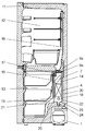
- FIG. 1 is a longitudinal sectional view of a refrigerator according to Embodiment 1 of the present invention.
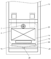
- FIG. 2 is a front view of the refrigerator door according to Embodiment 1 of the present invention with the door opened.
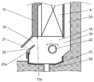
- FIG. 3 is a cross-sectional view of the vicinity of the return air passage of the refrigerator according to Embodiment 1 of the present invention.
- FIG. 4 is a configuration diagram of a refrigeration cycle of a conventional refrigerator.
- FIG. 1 is a longitudinal sectional view of the refrigerator according to Embodiment 1 of the present invention.
- FIG. 2 is a front view of a state in which the refrigerator door according to Embodiment 1 of the present invention is opened.
- FIG. 3 is a cross-sectional view of the vicinity of the return air passage of the refrigerator according to Embodiment 1 of the present invention.
- the refrigerator main body 11 composed of a heat insulating wall is provided with a refrigerator compartment 12 in the upper part and a freezer compartment 13 in the lower part.
- the refrigerator main body 11 includes a refrigerant circuit including a compressor 1, a condenser (not shown), a decompression device (not shown), and a cooler 4.
- the freezing chamber 13 includes a cooling chamber 14 that houses the cooler 4 therein.
- the cooling chamber 14 is partitioned from the inside of the freezer compartment 13 by a cooler cover 15.
- cooler 4 there are a cooling fan 7, a refrigerating room blower damper 9 a, and a freezer compartment blower damper 8 a for selectively circulating cold air (cooling air) generated by the cooler 4 to the refrigerating room 12 and the freezing room 13. I have.
- the inside of the refrigerator compartment blower damper 9a and the refrigerator compartment 12 communicates with the refrigerator compartment discharge air passage 16, and the refrigerator compartment fan damper 9a is opened so that the refrigerator compartment 12 and the refrigerator compartment 14 communicate with each other. That is, the refrigerator compartment air blower 9a selectively closes or opens the refrigerator compartment discharge air passage 16.
- the refrigerator compartment discharge air passage 16 guides the cooling air from the cooling fan 7 to the refrigerator compartment 12.
- the freezer compartment blower damper 8a and the inside of the freezer compartment 13 communicate with each other through a freezer compartment discharge air passage 17, and the freezer compartment 13 and the cooler compartment 14 communicate with each other when the freezer compartment blower damper 8a is opened. That is, the freezer compartment blower damper 8a selectively closes or opens the freezer compartment discharge air passage 17.
- the freezer compartment discharge air passage 17 guides the cooling air from the cooling fan 7 to the freezer compartment 13. During the operation of the cooling fan 7, the refrigerator air blow damper 9a and the freezer blower damper 8a are not opened simultaneously.
- a refrigeration room suction port 18 is provided on the back surface of the part below the cooler 4 of the cooling chamber 14, and a freezing room suction port 19 is provided on the front surface. 21 to communicate with each other. That is, the freezer compartment inlet 19 is provided on the surface facing the refrigerator compartment inlet 18 in the depth direction. Further, the refrigerator compartment return air passage 20 is provided between the cooling chamber 14 and the refrigerator body 11 with substantially the same width as or larger than the cooler 4. The refrigerating room return air passage 20 guides the cold air that has cooled the refrigerating room 12 to the cooling room 14 again.
- the freezer compartment return air passage 21 is provided below the cooler cover 15. The freezer compartment return air passage 21 guides the cold air that has cooled the freezer compartment 13 to the cooling chamber 14 again.
- a heating unit 22 such as a radiant heater that dissolves frost attached to the cooler 4 by a cooling operation is provided between the upper end and the lower end of the opening of the refrigerator compartment suction port 18. Further, below the heating unit 22, a water tray 23 and a drain pipe 24 are provided for discharging water generated when frost is thawed to the outside.
- a downwardly convex drainer 15 a is provided on the cooler 4 side at the lower end of the cooler cover 15.
- An inflow prevention wall 25 is provided at the lower part of the cooler cover 15.
- the inflow prevention wall 25 has a rectangular plate shape and is wider than at least the width of the refrigerator compartment suction port 18. Further, the inflow preventing wall 25 is provided with a fitting portion 25a with the wall in front of the water tray 23 at the lower part. Thereby, while eliminating the clearance gap between the inflow prevention wall 25 and the water receiving tray 23, the position variation of the inflow prevention wall 25 can be eliminated.
- the inflow prevention wall 25 is inclined so that the upper end is closer to the rear side of the refrigerator body 11 than the lower end, and is disposed at a position on the front side of the vertically downward projection surface of the cooler 4. .
- the inflow prevention wall 25 is provided between the refrigerator compartment suction port 18 and the freezer compartment inlet port 19, and the cold air discharged from the refrigerator compartment inlet port 18 flows backward from the freezer compartment inlet port 19 through the freezer compartment return air passage 21. Inflow to the freezer compartment 13 is prevented.
- the refrigerator When the refrigerator is operating, the internal temperature rises, the temperature of the freezer compartment 13 exceeds the reference temperature, and the freezer compartment 13 needs to be cooled. If the compressor 1 is stopped, the compressor 1 is operated. . On the other hand, when the compressor 1 has already been operated, the compressor 1 is continuously operated. And while the cooling fan 7 is drive
- the cold air generated by the cooler 4 flows from the freezer compartment blower damper 8a through the freezer compartment discharge air passage 17 and into the freezer compartment 13, thereby cooling the inside of the freezer compartment 13.
- the cold air that has cooled the freezer compartment 13 is sucked in the order of the freezer return air passage 21 and the freezer compartment suction port 19, is cooled again by the cooler 4, and is cooled by the cooling fan 7.
- the air is discharged from the air passage 17 into the freezer compartment 13.
- the cooling fan 7 is operated, the refrigerator compartment air damper 9a is opened, and the refrigerator compartment air damper 8a is closed.
- the cold air generated by the cooler 4 flows from the refrigerating chamber blower damper 9a through the refrigerating chamber discharge air passage 16 and into the refrigerating chamber 12, thereby cooling the inside of the refrigerating chamber 12.
- the cold air that has cooled the refrigerator compartment 12 is sucked in the order of the refrigerator compartment return air passage 20 and the refrigerator compartment suction port 18, and the cold air discharged from the refrigerator compartment suction port 18 is moved to the cooler 4 side by the inflow prevention wall 25. You can change the direction. Thereafter, the cool air is cooled again by the cooler 4 and is discharged by the cooling fan 7 from the refrigerating room blower damper 9 a and the refrigerating room discharge air passage 16 into the refrigerating room 12.
- the cold air sucked from the refrigerator compartment suction port 18 gets over the front wall of the water receiving tray 23 and flows backward from the freezer compartment suction port 19 through the freezer return air passage 21. And flows into the freezer compartment 13. At this time, the cold air flowing in from the refrigerator compartment suction port 18 is higher than the temperature in the freezer compartment 13 because the refrigerator compartment 12 is cooled, and the temperature of the freezer compartment 13 rises.
- the freezer compartment 13 is not heated by the cold air after the refrigerator compartment 12 is cooled while the refrigerator compartment 12 is being cooled. For this reason, the temperature rise of the freezer compartment 13 can be reliably suppressed with an inexpensive configuration, and a refrigerator with high cooling performance can be provided.
- the refrigerator return air passage 20 is provided between the cooling chamber 14 and the heat insulating wall on the back of the refrigerator main body 11 so as to have substantially the same width as or larger than that of the cooler 4. For this reason, the temperature difference between the outside air and the refrigerator main body 11 through the heat insulating wall can be reduced. As a result, heat transfer is reduced and the heat insulation effect is increased, but the temperature of the cold air flowing in the refrigerator return air path 20 is higher than that of the conventional configuration.
- the refrigerator air blow damper 8a is closed to circulate cold air only in the refrigerator compartment 12.
- the temperature of the cooler 4 can be raised compared with the case where there is no freezer compartment air damper 8a or the case where the freezer compartment air damper 8a is not closed during cooling of the refrigerator compartment 12.
- the efficiency of the cooling cycle during cooling the refrigerator compartment 12 is increased, but the temperature of the cold air flowing through the refrigerator return air passage 20 is further increased.
- the refrigerator compartment inlet 18 and the freezer compartment inlet 19 are opened vertically downward from the cooler 4. Thereby, the leakage of the cold air to the freezer compartment 13 can be prevented without reducing the lower fins of the cooler 4.
- the temperature rise of the freezer compartment 13 can be suppressed without reducing the capacity of the cooler 4, and a refrigerator with high cooling performance can be provided.
- the inflow prevention wall 25 is fixed to the water tray 23 by the fitting portion 25a. For this reason, the cool air that has cooled the refrigerator compartment 12 by the water receiving tray 23 and the inflow prevention wall 25 can be guided to the cooler 4. Thereby, the water tray 23 can be utilized as an air path, and the inflow prevention wall 25 can be made small. Moreover, since the inflow prevention wall 25 is fixed by the fitting part 25a with the water receiving tray 23, a gap is formed between the water receiving tray 23 and the inflow preventing wall 25 due to variations in component dimensions and assembly, and the cool air flows from the clearance into the freezer compartment. No leakage into 13.
- the inflow prevention wall 25 has an integral structure with the cooler cover 15. Thereby, since the number of parts can be reduced, the inflow prevention wall 25 can be comprised more inexpensively.
- the temperature increase of the freezer compartment 13 can be suppressed with a more inexpensive configuration, and a refrigerator with high cooling performance can be provided.
- the refrigerator compartment suction port 18 opens from a position higher than the heating unit 22 to a lower position. For this reason, the cold air that has cooled the refrigerator compartment 12 is sucked in from the refrigerator compartment suction port 18, and from the position lower than the heating unit 22, is sucked into the cooler 4 along the inflow prevention wall 25 from the water receiving tray 23, From the position higher than the heating unit 22, it is directly sucked into the cooler 4.
- the refrigerating room suction port 18 is opened at a height from a position higher than the heating unit 22 to a position lower than the heating unit 22, the pressure in the air passage is not reduced without reducing the internal volume. A loss can be suppressed small, the temperature rise of the freezer compartment 13 can be suppressed, and a refrigerator with high cooling performance can be provided.
- the inflow prevention wall 25 is located on a plane other than the vertically downward projection surface of the cooler 4, the defrost water generated when the operation of defrosting the frost attached to the cooler 4 is performed on the inflow prevention wall 25. It does not leak into the 13 freezer compartment.
- the cooler cover 15 is provided with a drainer 15a.
- a drainer 15a the inflow prevention wall 25 is configured at an angle such that the upper end of the inflow prevention wall 25 comes closer to the front side of the refrigerator body 11 than the drainer 15a. Thereby, the water dropped from the drainer 15a does not leak into the freezer compartment 13 through the inflow prevention wall 25.
- the temperature rise of the freezer compartment 13 can be suppressed while preventing water leakage into the freezer compartment 13, and a refrigerator with high cooling performance can be provided.
- the freezer compartment 13 is disposed below and the refrigerator compartment 12 is disposed above.
- the refrigerator compartment 13 and the refrigerator compartment 12 are disposed on the left and right. The same effect can be obtained with the above configuration.
- a refrigerator having two storage rooms that is, a freezer compartment 13 and a refrigerator compartment 12
- a suction port is provided at the front and back of the cooling compartment 14 in a refrigerator having two or more storage compartments. The same effect can be obtained if the refrigerator has a refrigerator.
- the refrigerator of the present invention includes the first storage chamber, the second storage chamber, the cooling chamber, the cooler, the cooling fan, the first discharge air passage, and the second discharge air.
- a road a first return air passage, and a second return air passage.
- the first storage chamber and the second storage chamber are surrounded by a heat insulating wall and have an opening on the front surface.
- the cooling chamber is provided on the back side of the second storage chamber.
- the cooler is provided in the cooling chamber.
- the cooling fan circulates the cold air generated by the cooler to the first storage chamber and the second storage chamber.
- the first discharge air passage guides the cooling air from the cooling fan into the first storage chamber.
- the second discharge air passage guides the cooling air from the cooling fan into the second storage chamber.
- the first return air path again guides the cooling air that has cooled the first storage chamber to the cooling chamber.
- the second return air path again guides the cooling air that has cooled the second storage chamber to the cooling chamber.
- the refrigerator of the present invention further includes a first opening and a second opening.
- the first opening guides the cooling air from the first return air passage to the cooling chamber.
- the second opening is provided on a surface facing the first opening in the depth direction, and guides the cooling air from the second return air passage to the cooling chamber.
- An inflow prevention wall is provided between the first opening and the second opening. The inflow prevention wall prevents the cooling air discharged from the first opening from flowing backward from the second opening through the second return air passage into the second storage chamber.
- the inflow prevention wall changes the direction of the cooling air discharged from the first opening toward the cooler.
- the cool air that has cooled the first storage chamber does not flow to the return air passage side of the first storage chamber, but can flow all to the cooler, which reliably increases the temperature of the second storage chamber. Can be suppressed.
- the first return air passage is provided on the back side of the cooling chamber, and the second return air passage is provided on the front side of the cooling chamber.
- this structure can be set as the structure with high heat insulation performance provided with the return air path whose temperature is higher than a cooler between a cooler and a heat insulation wall, and suppresses the temperature rise of the 2nd store room more. Can do.
- the first opening and the second opening are provided vertically below the cooler.
- This configuration allows the returning cold air to be sucked from the bottom of the cooler and allows the cool air to flow efficiently through the entire cooler. Thereby, the cooling efficiency of a refrigerator can be improved.
- a bowl-shaped water receiving tray is provided for receiving water from which frost attached to the cooler has been thawed.
- the cooling air discharged from the first opening is guided toward the cooler by the wall on the second opening side of the water tray and the inflow prevention wall.
- the cool air that has cooled the refrigerator compartment by the water tray and the inflow prevention wall can be smoothly guided to the cooler, and the inflow prevention wall can be made small. Thereby, the temperature rise of the second storage chamber can be suppressed at a lower cost.
- the first air passage blocking portion that selectively closes and opens the first discharge air passage
- the second air passage that selectively closes and opens the second discharge air passage.
- a blocking part is provided. During the cooling fan operation, the first air passage block and the second air passage block are not opened simultaneously.
- This configuration can prevent cold air that has cooled the first storage chamber from flowing into the second storage chamber. Thereby, the evaporation temperature at the time of cooling a 1st storage chamber can be made high, and the efficiency of a refrigerating cycle can be improved.
- the temperature of the first storage room is higher than the temperature of the second storage room.
- the inflow prevention wall is provided other than the vertically downward projection surface of the cooler.
- a fitting portion is provided between the inflow prevention wall and the water tray.
- This configuration makes it possible to configure the air path without creating a gap between the inflow prevention wall and the water tray. Thereby, there is no cold air leak from between an inflow prevention wall and a water tray, and the temperature rise of a freezer compartment can be suppressed more.
- the first discharge air passage, the first return air passage, the first closed portion, and the second closed portion are provided inside.
- a cover for partitioning the cooler and the second storage chamber is provided, and the cover and the inflow prevention wall are integrated.
- This configuration can reduce the number of parts. Thereby, while being able to comprise an air path at low cost, the variation of an assembly can be reduced and the temperature rise of a freezer compartment can be suppressed more at low cost.
- a heating unit that dissolves frost attached to the cooler is provided between the upper end and the lower end of the first opening.
- the air path resistance is reduced by the flow of cool air above and below the heating unit, and a reduction in the air volume of the cooling fan can be suppressed. Thereby, it can be set as a refrigerator with higher cooling efficiency.
- the present invention is a refrigerator including two storage rooms, and can provide a refrigerator that efficiently cools these storage rooms. Therefore, the present invention is useful as refrigerators of various types and sizes such as home use and business use.
- Cooler 7 Cooling fan 8a Freezer compartment blower damper (second air passage block) 9a Refrigeration room blower damper (first air passage blocker) 11 Refrigerator body 12 Refrigerated room (first storage room) 13 Freezer room (second storage room) 14 Cooling chamber 15 Cooler cover 16 Cooling chamber discharge air passage (first discharge air passage) 17 Freezer compartment discharge air passage (second discharge air passage) 18 Refrigerating room inlet (first opening) 19 Freezer compartment inlet (second opening) 20 Refrigerating room return air passage (first return air passage) 21 Freezer return air path (second return air path) 22 Heating part 23 Water tray 24 Drain pipe 25 Inflow prevention wall 25a Fitting part
Landscapes
- Engineering & Computer Science (AREA)
- Chemical & Material Sciences (AREA)
- Combustion & Propulsion (AREA)
- Physics & Mathematics (AREA)
- Mechanical Engineering (AREA)
- Thermal Sciences (AREA)
- General Engineering & Computer Science (AREA)
- Cold Air Circulating Systems And Constructional Details In Refrigerators (AREA)
Abstract
冷却室の奥行き方向の対抗する面に開口し、冷蔵室戻り風路からの冷却風を冷却室へと導く冷蔵室吸込口と、冷凍室戻り風路からの冷却風を冷却室へと導く冷凍室吸込口を設ける。冷蔵室吸込口と冷凍室吸込口の間に、冷蔵室吸込口から吐出した冷却風が冷凍室吸込口から冷凍室戻り風路を逆流して冷凍室内へと流入するのを防止する流入防止壁を備える。
Description
本発明は、冷蔵庫に関し、特に、二つの温度帯を持つ冷蔵庫において、一方の部屋を冷却した戻り空気が、他方の部屋に漏れることを防止する構造に関する。
図4は、従来の冷蔵庫の冷凍サイクル構成図である。図4において、冷凍サイクルは、圧縮機1、凝縮器2、減圧装置3、冷却器4を直列に接続した冷媒回路5、及び冷気通風路6により構成される。冷気通風路6は、冷却時間の調整などにより2つの温度帯に制御される温度帯の低い冷凍室(図示せず)及び温度帯の高い冷蔵室(図示せず)に冷気を通風させる。
冷気通風路6は、冷却器4、冷却ファン7、冷凍室送風ダンパ8a、冷蔵室送風ダンパ9a、冷凍室戻りダンパ8b、冷蔵室戻りダンパ9bを有している。冷却ファン7は、冷蔵庫内へ冷気を循環させる。冷凍室送風ダンパ8a、冷蔵室送風ダンパ9a、冷凍室戻りダンパ8b、冷蔵室戻りダンパ9bは冷凍室、冷蔵室へ選択的に冷気を循環させるため、送風路6a及び戻り風路6bそれぞれに設けられている。
このような冷蔵庫において、冷凍室が、ある設定温度以上になり、冷凍室のみを冷却する必要が生じた場合には、冷凍サイクルを運転するために、圧縮機1を運転すると共に、冷却ファン7を運転する。さらに、冷凍室送風ダンパ8a及び冷凍室戻りダンパ8bを開口し、冷蔵室送風ダンパ9a及び冷蔵室戻りダンパ9bを閉塞することにより、冷凍室のみを冷却する。
一方、冷蔵室がある設定温度以上になり、冷蔵室のみを冷却する必要が生じた場合には、冷蔵室送風ダンパ9a及び冷蔵室戻りダンパ9bを開口し、冷凍室送風ダンパ8a及び冷凍室戻りダンパ8bを閉塞することにより、冷蔵室のみを冷却する。
このように制御することにより、温度帯の高い冷蔵室を冷却する際に、温度帯の低い冷凍室への温度の高い冷気の流入を防止することができ、冷凍室の温度上昇を最小限に抑えることができる冷蔵庫が提案されている(例えば、特許文献1参照)。
また、他の方法として、冷蔵室を冷却した冷気を、冷却器4の背面下段から吸い込ませ、冷凍室側の戻り風路をそれより下方側に開口することにより、冷凍室側への逆流を防止する構成の冷蔵庫も商品化されている。
しかしながら、上記従来の構成では、冷気の流入を防止するための、冷凍室戻りダンパ8b及び冷蔵室戻りダンパ9bが必要である。このため、ダンパ追加によるコストアップ、冷蔵庫のダクトが複雑になる、ダンパ及び風路分の容積が必要となるため貯蔵室の容積が小さくなる、可動部品が増えることにより信頼性が低くなるなどの課題があった。
また、吸込口を冷却器4背面に設ける構成とすることもできる。しかし、このような構成では、冷却器4への着霜による目詰まりを防止するため、フィンアンドチューブ型の冷却器においては、冷却器4下段のフィンピッチを大きくしたり、フィンを無くしたりして対応する必要がある。このため、冷却器4の能力が低くなったり、能力を確保しようとすると冷却器4が大型化し、庫内容積が小さくなるなどの課題がある。
本発明の冷蔵庫は、第一の貯蔵室と第二の貯蔵室と、冷却室と、冷却器と、冷却ファンと、第一の吐出風路と、第二の吐出風路と、第一の戻り風路と、第二の戻り風路とを備える。第一の貯蔵室と第二の貯蔵室は、断熱壁で囲われ、前面に開口部を有する。冷却室は、第二の貯蔵室の背面側に設けられる。冷却器は、冷却室内に設けられる。冷却ファンは、冷却器で生成した冷気を第一の貯蔵室及び第二の貯蔵室へと循環させる。第一の吐出風路は、冷却ファンによる冷却風を第一の貯蔵室内へと導く。第二の吐出風路は、冷却ファンによる冷却風を第二の貯蔵室内へと導く。第一の戻り風路は、第一の貯蔵室を冷却した冷却風を冷却室へと再び導く。第二の戻り風路は、第二の貯蔵室を冷却した冷却風を冷却室へと再び導く。本発明の冷蔵庫は、さらに第一の開口と、第二の開口とを備える。第一の開口は、第一の戻り風路からの冷却風を冷却室へと導く。第二の開口は、奥行き方向において第一の開口と対向する面に設けられ、第二の戻り風路からの冷却風を冷却室へと導く。第一の開口と第二の開口の間に、流入防止壁が備えられる。流入防止壁は、第一の開口から吐出した冷却風が第二の開口から第二の戻り風路を逆流して第二の貯蔵室内へと流入するのを防止する。
この構成により、第一の貯蔵室を冷却した冷気が第二の貯蔵室に流入することを、簡単な構成で防止することができ、第二の貯蔵室の温度上昇を抑えることができる。
(実施の形態1)
図1は、本発明の実施の形態1における冷蔵庫の縦断面図である。図2は、本発明の実施の形態1における冷蔵庫のドアを開けた状態の正面図である。図3は、本発明の実施の形態1における冷蔵庫の戻り風路近傍の断面図である。
図1は、本発明の実施の形態1における冷蔵庫の縦断面図である。図2は、本発明の実施の形態1における冷蔵庫のドアを開けた状態の正面図である。図3は、本発明の実施の形態1における冷蔵庫の戻り風路近傍の断面図である。
図1から図3において、断熱壁で構成された冷蔵庫本体11は、上部に冷蔵室12、下部に冷凍室13を備えている。また、冷蔵庫本体11は内部に、圧縮機1、凝縮器(図示せず)、減圧装置(図示せず)、冷却器4からなる冷媒回路を備えている。
冷凍室13は、内部に冷却器4を収納する冷却室14を備えている。冷却室14は、冷凍室13庫内と冷却器カバー15により仕切られている。
冷却器4の上方には、冷却器4で生成した冷気(冷却風)を冷蔵室12及び冷凍室13へと選択的に循環させる冷却ファン7、冷蔵室送風ダンパ9a及び冷凍室送風ダンパ8aを備えている。
冷蔵室送風ダンパ9aと冷蔵室12庫内は冷蔵室吐出風路16により連通しており、冷蔵室送風ダンパ9aが開くことにより、冷蔵室12と冷却室14が連通する。すなわち、冷蔵室送風ダンパ9aは、冷蔵室吐出風路16を選択的に閉塞または開放する。冷蔵室吐出風路16は、冷却ファン7による冷却風を冷蔵室12へと導く。
冷凍室送風ダンパ8aと冷凍室13庫内は冷凍室吐出風路17により連通しており、冷凍室送風ダンパ8aが開くことにより、冷凍室13と冷却室14が連通する。すなわち、冷凍室送風ダンパ8aは、冷凍室吐出風路17を選択的に閉塞または開放する。冷凍室吐出風路17は、冷却ファン7による冷却風を冷凍室13へと導く。冷却ファン7の運転中は、冷蔵室送風ダンパ9aと冷凍室送風ダンパ8aは同時に開放しない。
冷却室14の冷却器4より下の部分の背面には冷蔵室吸込口18が、前面には冷凍室吸込口19が備えられており、それぞれ、冷蔵室戻り風路20及び冷凍室戻り風路21と、を連通するように開口している。すなわち、冷凍室吸込口19は、奥行き方向において冷蔵室吸込口18と対向する面に設けられている。また、冷蔵室戻り風路20は、冷却室14と冷蔵庫本体11の間に冷却器4とほぼ同じ幅でまたはそれ以上の幅で設けられている。冷蔵室戻り風路20は、冷蔵室12を冷却した冷気を冷却室14へと再び導く。冷凍室戻り風路21は、冷却器カバー15下部に設けられている。冷凍室戻り風路21は、冷凍室13を冷却した冷気を冷却室14へと再び導く。
冷却器4の下方には、冷却運転により冷却器4に付着した霜を解かすラジアントヒーターなどの加熱部22が冷蔵室吸込口18の開口の上端と下端の間に設けられている。さらに、加熱部22の下方には、霜を解かした際に発生する水を外部に排出するための水受け皿23及び排水パイプ24が設けられている。
また、冷却器カバー15の下端の冷却器4側には、下方向に凸形状の水切り15aが備えられている。
冷却器カバー15の下部には、流入防止壁25が備えられている。流入防止壁25は、長方形の板状の形状をしており、少なくとも冷蔵室吸込口18の幅よりも広い幅である。また、流入防止壁25は下部に水受け皿23の手前の壁との嵌合部25aを備えている。これにより、流入防止壁25と水受け皿23との隙間を無くすと共に、流入防止壁25の位置のバラツキを無くすことができる。
また、流入防止壁25は下端よりも上端が冷蔵庫本体11の背面側に近くなるように傾斜していると共に、冷却器4の鉛直下方向の投影面よりも前面側の位置に配置されている。流入防止壁25は、冷蔵室吸込口18と冷凍室吸込口19との間に設けられ、冷蔵室吸込口18から吐出した冷気が冷凍室吸込口19から冷凍室戻り風路21を逆流して冷凍室13へと流入するのを防止している。
以上のように構成された冷蔵庫について、以下その動作を説明する。
冷蔵庫運転時、庫内温度が上昇し、冷凍室13の温度が基準温度を超え、冷凍室13を冷却する必要がある場合、圧縮機1が停止している場合は圧縮機1が運転される。一方、圧縮機1がすでに運転している場合は圧縮機1が継続して運転される。そして、冷却ファン7が運転されると共に、冷凍室送風ダンパ8aが開かれ、冷蔵室送風ダンパ9aが閉じられる。
これにより、冷却器4で生成された冷気は冷凍室送風ダンパ8aから冷凍室吐出風路17を流れて冷凍室13内へと流れることにより冷凍室13内を冷却する。
この時、冷凍室13を冷却した冷気は、冷凍室戻り風路21、冷凍室吸込口19の順に吸い込まれ、再び冷却器4で冷却されて冷却ファン7により冷凍室送風ダンパ8a、冷凍室吐出風路17から冷凍室13庫内へと吐出される。
一方、冷蔵室12の温度が基準温度を超え、冷蔵室12を冷却する必要がある場合、冷却ファン7が運転されると共に、冷蔵室送風ダンパ9aが開かれ、冷凍室送風ダンパ8aが閉じられる。
これにより、冷却器4で生成された冷気は冷蔵室送風ダンパ9aから冷蔵室吐出風路16を流れて冷蔵室12内へと流れることにより、冷蔵室12内を冷却する。
この時、冷蔵室12を冷却した冷気は、冷蔵室戻り風路20、冷蔵室吸込口18の順に吸い込まれ、冷蔵室吸込口18から吐出された冷気が流入防止壁25により冷却器4側へと向きを変えられる。その後、冷気は再び冷却器4で冷却されて冷却ファン7により冷蔵室送風ダンパ9a、冷蔵室吐出風路16から冷蔵室12庫内へと吐出される。
ここで、流入防止壁25が無かった場合、冷蔵室吸込口18から吸い込まれた冷気は、水受け皿23の前面の壁を乗り越えて、冷凍室吸込口19から冷凍室戻り風路21を逆流して冷凍室13内へと流入する。この時、冷蔵室吸込口18から流入する冷気は、冷蔵室12を冷却したため冷凍室13内の温度よりも高くなっており、冷凍室13の温度が上昇する。
これに対して、流入防止壁25がある場合は、冷蔵室吸込口18から吸い込まれた冷気は、水受け皿23から流入防止壁25に沿って流れる。これにより、冷気の流れの方向が冷却器4側へと変えられるため、冷凍室吸込口19の方向へと流れることはない。
従って、従来例のようなダンパを冷凍室吸込口19に設けなくても冷蔵室12を冷却中に冷凍室13が冷蔵室12を冷却した後の冷気により暖められることが無い。このため、安価な構成で確実に冷凍室13の温度上昇を抑えることができ、冷却性能の高い冷蔵庫を提供することができる。
また、冷蔵室戻り風路20は冷却室14と冷蔵庫本体11の背面の断熱壁との間に冷却器4とほぼ同じ幅またはそれ以上の幅で設けている。このため、断熱壁を介した外気と冷蔵庫本体11内の温度差を小さくできる。その結果、熱移動が少なくなり断熱効果は高くなるが、冷蔵室戻り風路20内を流れる冷気は従来の構成に比べて温度が高くなる。
さらに、冷蔵室12を冷却している時は、冷凍室送風ダンパ8aを閉じることにより、冷蔵室12のみに冷気を循環させる構成としている。これにより、冷凍室送風ダンパ8aが無い場合や、冷蔵室12冷却中に冷凍室送風ダンパ8aが閉じない場合に比べて冷却器4の温度を高くすることができる。その結果、冷蔵室12を冷却中の冷却サイクルの効率は高くなるが、冷蔵室戻り風路20内を流れる冷気の温度がさらに高くなる。
このような構成においても確実に冷凍室13への冷気の漏れを防止することができる。
従って、より断熱効果の高い冷蔵庫においても冷凍室13の温度上昇を抑えることができ、冷却性能の高い冷蔵庫を提供することができる。
また、本実施の形態の冷蔵庫においては、冷蔵室吸込口18と冷凍室吸込口19は冷却器4よりも鉛直下方側で開口している。これにより、冷却器4の下段のフィンを少なくすることなく冷凍室13への冷気の漏れを防止することができる。
従って、冷却器4の能力を低下させることなく冷凍室13の温度上昇を抑えることができ、冷却性能の高い冷蔵庫を提供することができる。
また、流入防止壁25は、嵌合部25aによって水受け皿23と固定されている。このため、水受け皿23と流入防止壁25によって冷蔵室12を冷却した冷気を冷却器4へと導くことができる。これにより、水受け皿23を風路として利用でき、流入防止壁25を小さくすることができる。また、水受け皿23との嵌合部25aで流入防止壁25が固定されるため、部品寸法や組み立てのバラツキにより水受け皿23と流入防止壁25の間に隙間ができ、冷気が隙間から冷凍室13内へと漏れることがない。
従って、より安価な構成で、より確実に冷凍室13の温度上昇を抑えることができ、冷却性能の高い冷蔵庫を提供することができる。
また、流入防止壁25は冷却器カバー15と一体構造としている。これにより、部品点数を減らすことができるため、より安価に流入防止壁25を構成することができる。
従って、より安価な構成で冷凍室13の温度上昇を抑えることができ、冷却性能の高い冷蔵庫を提供することができる。
また、冷蔵室吸込口18は、加熱部22よりも高い位置から低い位置まで開口している。このため、冷蔵室12を冷却した冷気は、冷蔵室吸込口18より吸い込まれ、加熱部22よりも低い位置からは、水受け皿23から流入防止壁25に沿って冷却器4へと吸い込まれ、加熱部22よりも高い位置からは、直接、冷却器4へと吸い込まれる。
これに対し、冷蔵室吸込口18が加熱部22より高い位置のみで開口している場合は冷蔵室吸込口18からの冷気は冷却器4へと吸い込まれる際に方向が急激に変えられることにより圧力損失が大きくなる。
また、冷蔵室吸込口18が加熱部22より低い位置のみで開口している場合は、冷蔵室吸込口18から吸い込まれた冷気は全て水受け皿23から流入防止壁25へと流れ、風速が速くなる。このため、冷凍室13内へ冷気が漏れるのを防止するために、より流入防止壁25を冷却器4側へ傾ける必要があり、圧力損失が大きくなる。
また、圧力損失を減らすため、加熱部22を、冷蔵室吸込口18から離す構成とする場合は、安全確保のため、加熱部22と周囲の部品の距離をある程度取る必要がある。このために、冷却室14が大きくなり、庫内容積が小さくなってしまう。
従って、本実施の形態のように、冷蔵室吸込口18が、加熱部22よりも高い位置から低い位置までの高さで開口していれば、庫内容積を減らすことなく、風路の圧力損失を小さく抑えて冷凍室13の温度上昇を抑えることができ、冷却性能の高い冷蔵庫を提供することができる。
また、流入防止壁25は、冷却器4の鉛直下方向の投影面以外にあるため、冷却器4に付着した霜を解かす動作を行った際に発生する除霜水が流入防止壁25を伝って冷凍室13庫内へと漏れ出ることは無い。
さらに、冷却器カバー15には水切り15aを備えている。これにより、冷却器4表面で解けた水が冷却器カバー15を伝って流れてきても、水切り15a部で下方向に落下する。このため、水が冷却器カバー15を伝って冷凍室13内へ漏れ出ることは無い。この時、流入防止壁25を、流入防止壁25の上端が水切り15aよりも冷蔵庫本体11の前面側に来るような角度で構成する。これにより、水切り15aから落下した水が流入防止壁25を伝って冷凍室13内へ漏れ出ることも無い。
従って、冷凍室13内への水漏れを防止しつつ冷凍室13の温度上昇を抑えることができ、冷却性能の高い冷蔵庫を提供することができる。
尚、本実施の形態において、冷凍室13を下、冷蔵室12を上に配置した構成としたが、2つの温度帯を持った冷蔵庫であれば、冷凍室13と冷蔵室12を左右に配置した構成でも同様の効果が得られる。
また、本実施の形態においては、冷凍室13と冷蔵室12の2つの貯蔵室を持った冷蔵庫で説明したが、2つ以上の貯蔵室を持つ冷蔵庫で冷却室14の前面と背面に吸込口を持つ冷蔵庫であれば、同様の効果を得られる。
また、本実施の形態においては、圧縮機1を用いた冷媒圧縮式冷凍サイクルによって冷気を生成する冷凍システムで説明したが、冷却器4で冷気を生成する冷凍システムであれば、いかなる冷凍システムであっても同様の効果を得られる。
以上説明したように、本発明の冷蔵庫は、第一の貯蔵室と第二の貯蔵室と、冷却室と、冷却器と、冷却ファンと、第一の吐出風路と、第二の吐出風路と、第一の戻り風路と、第二の戻り風路とを備える。第一の貯蔵室と第二の貯蔵室は、断熱壁で囲われ、前面に開口部を有する。冷却室は、第二の貯蔵室の背面側に設けられる。冷却器は、冷却室内に設けられる。冷却ファンは、冷却器で生成した冷気を第一の貯蔵室及び第二の貯蔵室へと循環させる。第一の吐出風路は、冷却ファンによる冷却風を第一の貯蔵室内へと導く。第二の吐出風路は、冷却ファンによる冷却風を第二の貯蔵室内へと導く。第一の戻り風路は、第一の貯蔵室を冷却した冷却風を冷却室へと再び導く。第二の戻り風路は、第二の貯蔵室を冷却した冷却風を冷却室へと再び導く。本発明の冷蔵庫は、さらに第一の開口と、第二の開口とを備える。第一の開口は、第一の戻り風路からの冷却風を冷却室へと導く。第二の開口は、奥行き方向において第一の開口と対向する面に設けられ、第二の戻り風路からの冷却風を冷却室へと導く。第一の開口と第二の開口の間に、流入防止壁が備えられる。流入防止壁は、第一の開口から吐出した冷却風が第二の開口から第二の戻り風路を逆流して第二の貯蔵室内へと流入するのを防止する。
この構成により、第一の貯蔵室を冷却した冷気が第二の貯蔵室に流入することを、簡単な構成で防止することができ、第二の貯蔵室の温度上昇を抑えることができる。
また、本発明の冷蔵庫では、流入防止壁は、第一の開口から吐出した冷却風を冷却器の方向へと向きを変える。
この構成により、第一の貯蔵室を冷却した冷気は、第一の貯蔵室の戻り風路側には流れず、全て冷却器へと流すことができ、確実に第二の貯蔵室の温度上昇を抑えることができる。
また、本発明の冷蔵庫では、第一の戻り風路を冷却室の背面側に設け、第二の戻り風路を冷却室の前面側に設ける。
この構成により、冷却器と断熱壁との間に冷却器よりも温度の高い戻り風路を備えた、断熱性能が高い構成とすることができ、より第二の貯蔵室の温度上昇を抑えることができる。
また、本発明の冷蔵庫では、第一の開口と第二の開口は冷却器より鉛直下方側に設ける。
この構成により、戻りの冷気を冷却器の下から吸い込ませることができ、冷却器全体に効率よく冷気を流すことができる。これにより、冷蔵庫の冷却効率を高めることができる。
また、本発明の冷蔵庫では、冷却器に付着した霜を解かした水を受ける椀状の水受け皿を設ける。水受け皿の第二の開口側の壁と流入防止壁により第一の開口から吐出した冷却風を冷却器の方向へと導く。
この構成により、水受け皿と流入防止壁によって冷蔵室を冷却した冷気を冷却器へとスムーズに導くことができ、流入防止壁を小さくすることができる。これにより、より低コストで第二の貯蔵室の温度上昇を抑えることができる。
また、本発明の冷蔵庫では、第一の吐出風路を選択的に閉塞、開放する第一の風路閉塞部と、第二の吐出風路を選択的に閉塞、開放する第二の風路閉塞部とを設ける。冷却ファン運転中は第一の風路閉塞部と第二の風路閉塞部を同時に開放しない。
この構成により、第一の貯蔵室を単独で冷却した冷気が第二の貯蔵室に流入するのを防止することができる。これにより、第一の貯蔵室を冷却する際の蒸発温度を高くすることができ、冷凍サイクルの効率を高めることができる。
また、本発明の冷蔵庫では、第一の貯蔵室の温度が第二の貯蔵室の温度よりも高い。
この構成により、冷却器と断熱壁との間に、より温度の高い冷蔵室からの戻り風路を備えた、断熱性能が高い構成とすることができる。これにより、より冷凍室の温度上昇を抑えることができる。
また、本発明の冷蔵庫では、流入防止壁を冷却器の鉛直下方向の投影面以外に設ける。
この構成により、冷却器を除霜した際に発生する水が流入防止壁を伝い、冷凍室内へと流れることはない。これにより、冷凍室庫内での異常な霜付き、氷結を防止することができる。
また、本発明の冷蔵庫では、流入防止壁と水受け皿の間に嵌合部を設ける。
この構成により、流入防止壁と水受け皿の間に隙間を作ることが無く風路を構成できる。これにより、流入防止壁と水受け皿の間からの冷気漏れが無く、より冷凍室の温度上昇を抑えることができる。
また、本発明の冷蔵庫では、第一の吐出風路、第一の戻り風路、第一の閉塞部及び第二の閉塞部を内部に備える。冷却器と第二の貯蔵室内を仕切るカバーを設け、カバーと流入防止壁を一体構造とする。
この構成により、部品点数を減らすことができる。これにより、低コストで風路を構成することができると共に、組立のバラツキを減らすことができ、より低コストで冷凍室の温度上昇をより抑えることができる。
また、本発明の冷蔵庫では、冷却器に付着した霜を解かす加熱部を、第一の開口の上端と下端の間に設ける。
この構成により、加熱部の上下を冷気が流れることにより風路抵抗が小さくなり、冷却ファンの風量低下を抑制することができる。これにより、より冷却効率の高い冷蔵庫とすることができる。
本発明は、2つの貯蔵室を備える冷蔵庫であって、これらの貯蔵室の冷却を効率よく行う冷蔵庫を提供することができる。従って、本発明は、家庭用および業務用など様々な種類及び大きさの冷蔵庫等として有用である。
4 冷却器
7 冷却ファン
8a 冷凍室送風ダンパ(第二の風路閉塞部)
9a 冷蔵室送風ダンパ(第一の風路閉塞部)
11 冷蔵庫本体
12 冷蔵室(第一の貯蔵室)
13 冷凍室(第二の貯蔵室)
14 冷却室
15 冷却器カバー
16 冷蔵室吐出風路(第一の吐出風路)
17 冷凍室吐出風路(第二の吐出風路)
18 冷蔵室吸込口(第一の開口)
19 冷凍室吸込口(第二の開口)
20 冷蔵室戻り風路(第一の戻り風路)
21 冷凍室戻り風路(第二の戻り風路)
22 加熱部
23 水受け皿
24 排水パイプ
25 流入防止壁
25a 嵌合部
7 冷却ファン
8a 冷凍室送風ダンパ(第二の風路閉塞部)
9a 冷蔵室送風ダンパ(第一の風路閉塞部)
11 冷蔵庫本体
12 冷蔵室(第一の貯蔵室)
13 冷凍室(第二の貯蔵室)
14 冷却室
15 冷却器カバー
16 冷蔵室吐出風路(第一の吐出風路)
17 冷凍室吐出風路(第二の吐出風路)
18 冷蔵室吸込口(第一の開口)
19 冷凍室吸込口(第二の開口)
20 冷蔵室戻り風路(第一の戻り風路)
21 冷凍室戻り風路(第二の戻り風路)
22 加熱部
23 水受け皿
24 排水パイプ
25 流入防止壁
25a 嵌合部
Claims (11)
- 断熱壁で囲われ、前面に開口部を有した第一の貯蔵室と第二の貯蔵室と、
前記第二の貯蔵室の背面側に設けた冷却室と、
前記冷却室内に設けた冷却器と、
前記冷却器で生成した冷気を前記第一の貯蔵室及び前記第二の貯蔵室へと循環させる冷却ファンと、
前記冷却ファンによる冷却風を前記第一の貯蔵室内へと導く第一の吐出風路と、前記冷却ファンによる冷却風を前記第二の貯蔵室内へと導く第二の吐出風路と、前記第一の貯蔵室を冷却した冷却風を前記冷却室へと再び導く第一の戻り風路と、
前記第二の貯蔵室を冷却した冷却風を前記冷却室へと再び導く第二の戻り風路と、を設けた冷蔵庫において、
前記第一の戻り風路からの冷却風を前記冷却室へと導く第一の開口と、
奥行き方向において前記第一の開口と対向する面に設けられ、前記第二の戻り風路からの冷却風を前記冷却室へと導く第二の開口とを設け、
前記第一の開口と前記第二の開口の間に、前記第一の開口から吐出した冷却風が前記第二の開口から前記第二の戻り風路を逆流して前記第二の貯蔵室内へと流入するのを防止する流入防止壁を備えた冷蔵庫。 - 前記流入防止壁は、前記第一の開口から吐出した冷却風を前記冷却器の方向へと向きを変えることを特徴とした請求項1に記載の冷蔵庫。
- 前記第一の戻り風路を前記冷却室の背面側に設け、前記第二の戻り風路を前記冷却室の前面側に設けたことを特徴とした請求項1に記載の冷蔵庫。
- 前記第一の開口と前記第二の開口は、前記冷却器より鉛直下方側に設けたことを特徴とした請求項1に記載の冷蔵庫。
- 前記冷却器に付着した霜を解かした水を受ける椀状の水受け皿を設け、前記水受け皿の前記第二の開口側の壁と前記流入防止壁により、前記第一の開口から吐出した冷却風を前記冷却器の方向へと導くことを特徴とした請求項1に記載の冷蔵庫。
- 前記第一の吐出風路を選択的に閉塞または開放する第一の風路閉塞部と、前記第二の吐出風路を選択的に閉塞または開放する第二の風路閉塞部とを設け、前記冷却ファンの運転中は前記第一の風路閉塞部と前記第二の風路閉塞部を同時に開放しないことを特徴とした請求項1に記載の冷蔵庫。
- 前記第一の貯蔵室の温度が前記第二の貯蔵室の温度よりも高いことを特徴とした請求項1に記載の冷蔵庫。
- 前記流入防止壁を前記冷却器の鉛直下方向の投影面以外に設けることを特徴とした請求項1に記載の冷蔵庫。
- 前記流入防止壁と前記水受け皿の間に嵌合部を設けることを特徴とした請求項1に記載の冷蔵庫。
- 前記第一の吐出風路、前記第一の戻り風路、前記第一の風路閉塞部及び前記第二の風路閉塞部を内部に備えるとともに、前記冷却器と前記第二の貯蔵室内を仕切るカバーを設け、前記カバーと前記流入防止壁を一体構造とすることを特徴とした請求項6に記載の冷蔵庫。
- 前記冷却器に付着した霜を解かす加熱部を、前記第一の開口の上端と下端の間に設けたことを特徴とした請求項1に記載の冷蔵庫。
Priority Applications (2)
| Application Number | Priority Date | Filing Date | Title |
|---|---|---|---|
| CN201280047879.4A CN103827608B (zh) | 2011-09-29 | 2012-09-13 | 冷藏库 |
| EP12837519.3A EP2762808B1 (en) | 2011-09-29 | 2012-09-13 | Refrigerator |
Applications Claiming Priority (2)
| Application Number | Priority Date | Filing Date | Title |
|---|---|---|---|
| JP2011-213943 | 2011-09-29 | ||
| JP2011213943A JP5903552B2 (ja) | 2011-09-29 | 2011-09-29 | 冷蔵庫 |
Publications (1)
| Publication Number | Publication Date |
|---|---|
| WO2013046580A1 true WO2013046580A1 (ja) | 2013-04-04 |
Family
ID=47994669
Family Applications (1)
| Application Number | Title | Priority Date | Filing Date |
|---|---|---|---|
| PCT/JP2012/005831 Ceased WO2013046580A1 (ja) | 2011-09-29 | 2012-09-13 | 冷蔵庫 |
Country Status (4)
| Country | Link |
|---|---|
| EP (1) | EP2762808B1 (ja) |
| JP (1) | JP5903552B2 (ja) |
| CN (1) | CN103827608B (ja) |
| WO (1) | WO2013046580A1 (ja) |
Cited By (11)
| Publication number | Priority date | Publication date | Assignee | Title |
|---|---|---|---|---|
| WO2014196210A1 (ja) * | 2013-06-06 | 2014-12-11 | パナソニックIpマネジメント株式会社 | 冷蔵庫 |
| JP2014238185A (ja) * | 2013-06-06 | 2014-12-18 | パナソニック株式会社 | 冷蔵庫 |
| JP2014238183A (ja) * | 2013-06-06 | 2014-12-18 | パナソニックIpマネジメント株式会社 | 冷蔵庫 |
| JP2014238186A (ja) * | 2013-06-06 | 2014-12-18 | パナソニックIpマネジメント株式会社 | 冷蔵庫 |
| JP2014238181A (ja) * | 2013-06-06 | 2014-12-18 | パナソニック株式会社 | 冷蔵庫 |
| JP2014238182A (ja) * | 2013-06-06 | 2014-12-18 | パナソニックIpマネジメント株式会社 | 冷蔵庫 |
| JP2015222129A (ja) * | 2014-05-22 | 2015-12-10 | パナソニックIpマネジメント株式会社 | 冷蔵庫 |
| JP2017096586A (ja) * | 2015-11-27 | 2017-06-01 | 日立アプライアンス株式会社 | 冷蔵庫 |
| WO2018025353A1 (ja) * | 2016-08-03 | 2018-02-08 | 三菱電機株式会社 | 冷蔵庫 |
| JP2018025323A (ja) * | 2016-08-09 | 2018-02-15 | 日立アプライアンス株式会社 | 冷蔵庫 |
| JP2021012019A (ja) * | 2020-11-04 | 2021-02-04 | 日立グローバルライフソリューションズ株式会社 | 冷蔵庫 |
Families Citing this family (7)
| Publication number | Priority date | Publication date | Assignee | Title |
|---|---|---|---|---|
| WO2013084460A1 (ja) * | 2011-12-06 | 2013-06-13 | パナソニック株式会社 | 冷蔵庫 |
| JP6405525B2 (ja) * | 2014-05-22 | 2018-10-17 | パナソニックIpマネジメント株式会社 | 冷蔵庫 |
| CN105783383A (zh) * | 2016-05-17 | 2016-07-20 | 合肥美菱股份有限公司 | 一种冰箱的风路系统及其冰箱 |
| JP7223581B2 (ja) * | 2019-01-23 | 2023-02-16 | 日立グローバルライフソリューションズ株式会社 | 冷蔵庫 |
| JP2022065292A (ja) * | 2020-10-15 | 2022-04-27 | シャープ株式会社 | 冷蔵庫 |
| CN114992945B (zh) * | 2022-06-01 | 2026-04-07 | 青岛海尔电冰箱有限公司 | 一种冰箱 |
| CN118111163A (zh) * | 2022-11-30 | 2024-05-31 | 青岛海尔电冰箱有限公司 | 冰箱 |
Citations (9)
| Publication number | Priority date | Publication date | Assignee | Title |
|---|---|---|---|---|
| JPS62204282U (ja) * | 1986-06-16 | 1987-12-26 | ||
| JPH08327208A (ja) * | 1995-04-06 | 1996-12-13 | Daewoo Electronics Co Ltd | 冷蔵庫及び冷蔵庫の冷気循環方法 |
| JPH10318655A (ja) * | 1997-05-16 | 1998-12-04 | Sharp Corp | 冷凍冷蔵庫 |
| JPH11183021A (ja) * | 1990-06-01 | 1999-07-06 | Hitachi Ltd | 冷蔵庫 |
| JP2002013862A (ja) * | 2000-06-28 | 2002-01-18 | Sharp Corp | 冷蔵庫 |
| JP2002195725A (ja) * | 2000-12-26 | 2002-07-10 | Mitsubishi Electric Corp | 冷凍冷蔵庫、冷凍冷蔵庫の運転方法 |
| JP2003075048A (ja) * | 2001-08-31 | 2003-03-12 | Fujitsu General Ltd | 電気冷蔵庫 |
| JP2004069245A (ja) | 2002-08-09 | 2004-03-04 | Hitachi Home & Life Solutions Inc | 冷蔵庫 |
| JP2004085070A (ja) * | 2002-08-27 | 2004-03-18 | Matsushita Refrig Co Ltd | 冷蔵庫 |
Family Cites Families (6)
| Publication number | Priority date | Publication date | Assignee | Title |
|---|---|---|---|---|
| JP2000180018A (ja) * | 1998-12-18 | 2000-06-30 | Fujitsu General Ltd | 冷蔵庫 |
| JP2002147922A (ja) * | 2000-11-06 | 2002-05-22 | Fujitsu General Ltd | 冷蔵庫 |
| JP2002318055A (ja) * | 2001-04-20 | 2002-10-31 | Fujitsu General Ltd | 冷蔵庫 |
| US20060248915A1 (en) * | 2005-05-06 | 2006-11-09 | Samsung Electronics Co., Ltd. | Refrigerator |
| DE102008042908A1 (de) * | 2008-10-16 | 2010-04-22 | BSH Bosch und Siemens Hausgeräte GmbH | Kältegerät mit Kaltluftkanal |
| BR112012002487B8 (pt) * | 2009-09-24 | 2020-10-27 | Panasonic Corp | refrigerador |
-
2011
- 2011-09-29 JP JP2011213943A patent/JP5903552B2/ja not_active Expired - Fee Related
-
2012
- 2012-09-13 WO PCT/JP2012/005831 patent/WO2013046580A1/ja not_active Ceased
- 2012-09-13 EP EP12837519.3A patent/EP2762808B1/en not_active Not-in-force
- 2012-09-13 CN CN201280047879.4A patent/CN103827608B/zh active Active
Patent Citations (9)
| Publication number | Priority date | Publication date | Assignee | Title |
|---|---|---|---|---|
| JPS62204282U (ja) * | 1986-06-16 | 1987-12-26 | ||
| JPH11183021A (ja) * | 1990-06-01 | 1999-07-06 | Hitachi Ltd | 冷蔵庫 |
| JPH08327208A (ja) * | 1995-04-06 | 1996-12-13 | Daewoo Electronics Co Ltd | 冷蔵庫及び冷蔵庫の冷気循環方法 |
| JPH10318655A (ja) * | 1997-05-16 | 1998-12-04 | Sharp Corp | 冷凍冷蔵庫 |
| JP2002013862A (ja) * | 2000-06-28 | 2002-01-18 | Sharp Corp | 冷蔵庫 |
| JP2002195725A (ja) * | 2000-12-26 | 2002-07-10 | Mitsubishi Electric Corp | 冷凍冷蔵庫、冷凍冷蔵庫の運転方法 |
| JP2003075048A (ja) * | 2001-08-31 | 2003-03-12 | Fujitsu General Ltd | 電気冷蔵庫 |
| JP2004069245A (ja) | 2002-08-09 | 2004-03-04 | Hitachi Home & Life Solutions Inc | 冷蔵庫 |
| JP2004085070A (ja) * | 2002-08-27 | 2004-03-18 | Matsushita Refrig Co Ltd | 冷蔵庫 |
Non-Patent Citations (1)
| Title |
|---|
| See also references of EP2762808A4 * |
Cited By (13)
| Publication number | Priority date | Publication date | Assignee | Title |
|---|---|---|---|---|
| WO2014196210A1 (ja) * | 2013-06-06 | 2014-12-11 | パナソニックIpマネジメント株式会社 | 冷蔵庫 |
| JP2014238185A (ja) * | 2013-06-06 | 2014-12-18 | パナソニック株式会社 | 冷蔵庫 |
| JP2014238183A (ja) * | 2013-06-06 | 2014-12-18 | パナソニックIpマネジメント株式会社 | 冷蔵庫 |
| JP2014238186A (ja) * | 2013-06-06 | 2014-12-18 | パナソニックIpマネジメント株式会社 | 冷蔵庫 |
| JP2014238181A (ja) * | 2013-06-06 | 2014-12-18 | パナソニック株式会社 | 冷蔵庫 |
| JP2014238182A (ja) * | 2013-06-06 | 2014-12-18 | パナソニックIpマネジメント株式会社 | 冷蔵庫 |
| JP2015222129A (ja) * | 2014-05-22 | 2015-12-10 | パナソニックIpマネジメント株式会社 | 冷蔵庫 |
| JP2017096586A (ja) * | 2015-11-27 | 2017-06-01 | 日立アプライアンス株式会社 | 冷蔵庫 |
| WO2018025353A1 (ja) * | 2016-08-03 | 2018-02-08 | 三菱電機株式会社 | 冷蔵庫 |
| JPWO2018025353A1 (ja) * | 2016-08-03 | 2019-02-28 | 三菱電機株式会社 | 冷蔵庫 |
| JP2018025323A (ja) * | 2016-08-09 | 2018-02-15 | 日立アプライアンス株式会社 | 冷蔵庫 |
| JP2021012019A (ja) * | 2020-11-04 | 2021-02-04 | 日立グローバルライフソリューションズ株式会社 | 冷蔵庫 |
| JP7063970B2 (ja) | 2020-11-04 | 2022-05-09 | 日立グローバルライフソリューションズ株式会社 | 冷蔵庫 |
Also Published As
| Publication number | Publication date |
|---|---|
| CN103827608B (zh) | 2016-01-20 |
| JP2013072617A (ja) | 2013-04-22 |
| EP2762808B1 (en) | 2016-11-02 |
| JP5903552B2 (ja) | 2016-04-13 |
| CN103827608A (zh) | 2014-05-28 |
| EP2762808A4 (en) | 2015-06-17 |
| EP2762808A1 (en) | 2014-08-06 |
Similar Documents
| Publication | Publication Date | Title |
|---|---|---|
| JP5903552B2 (ja) | 冷蔵庫 | |
| US10883755B2 (en) | Refrigerator | |
| KR102126401B1 (ko) | 냉장고 및 냉장고 제어 방법 | |
| KR101396956B1 (ko) | 냉장고 | |
| CN105814378B (zh) | 冰箱 | |
| JP2009079807A (ja) | 冷蔵庫 | |
| WO2019107066A1 (ja) | 冷蔵庫 | |
| JP2013057415A (ja) | 冷蔵庫 | |
| KR101659011B1 (ko) | 냉장고 | |
| JP6539093B2 (ja) | 冷蔵庫 | |
| JP6803217B2 (ja) | 冷蔵庫 | |
| JP2025065399A (ja) | 冷蔵庫 | |
| KR101559786B1 (ko) | 냉장고 | |
| JP2006017338A (ja) | 冷蔵庫 | |
| JP2014048029A (ja) | 冷蔵庫 | |
| JP5895145B2 (ja) | 冷蔵庫 | |
| JP4599207B2 (ja) | ショーケース | |
| US11852387B2 (en) | Refrigerator | |
| CN112066620A (zh) | 冰箱 | |
| JP6940424B2 (ja) | 冷蔵庫 | |
| WO2017163965A1 (ja) | 冷蔵庫 | |
| CN221527012U (zh) | 冰箱 | |
| JP2015001325A (ja) | 冷蔵庫 | |
| JP2012241975A (ja) | 冷蔵庫 | |
| CN120176366A (zh) | 冰箱及其控制方法 |
Legal Events
| Date | Code | Title | Description |
|---|---|---|---|
| 121 | Ep: the epo has been informed by wipo that ep was designated in this application |
Ref document number: 12837519 Country of ref document: EP Kind code of ref document: A1 |
|
| REEP | Request for entry into the european phase |
Ref document number: 2012837519 Country of ref document: EP |
|
| WWE | Wipo information: entry into national phase |
Ref document number: 2012837519 Country of ref document: EP |
|
| NENP | Non-entry into the national phase |
Ref country code: DE |