WO2013047548A1 - 摺動特性に優れた被覆部材 - Google Patents
摺動特性に優れた被覆部材 Download PDFInfo
- Publication number
- WO2013047548A1 WO2013047548A1 PCT/JP2012/074627 JP2012074627W WO2013047548A1 WO 2013047548 A1 WO2013047548 A1 WO 2013047548A1 JP 2012074627 W JP2012074627 W JP 2012074627W WO 2013047548 A1 WO2013047548 A1 WO 2013047548A1
- Authority
- WO
- WIPO (PCT)
- Prior art keywords
- layer
- film
- covering member
- thickness
- sliding
- Prior art date
- Legal status (The legal status is an assumption and is not a legal conclusion. Google has not performed a legal analysis and makes no representation as to the accuracy of the status listed.)
- Ceased
Links
Images



Classifications
-
- B—PERFORMING OPERATIONS; TRANSPORTING
- B21—MECHANICAL METAL-WORKING WITHOUT ESSENTIALLY REMOVING MATERIAL; PUNCHING METAL
- B21J—FORGING; HAMMERING; PRESSING METAL; RIVETING; FORGE FURNACES
- B21J13/00—Details of machines for forging, pressing, or hammering
- B21J13/02—Dies or mountings therefor
-
- C—CHEMISTRY; METALLURGY
- C23—COATING METALLIC MATERIAL; COATING MATERIAL WITH METALLIC MATERIAL; CHEMICAL SURFACE TREATMENT; DIFFUSION TREATMENT OF METALLIC MATERIAL; COATING BY VACUUM EVAPORATION, BY SPUTTERING, BY ION IMPLANTATION OR BY CHEMICAL VAPOUR DEPOSITION, IN GENERAL; INHIBITING CORROSION OF METALLIC MATERIAL OR INCRUSTATION IN GENERAL
- C23C—COATING METALLIC MATERIAL; COATING MATERIAL WITH METALLIC MATERIAL; SURFACE TREATMENT OF METALLIC MATERIAL BY DIFFUSION INTO THE SURFACE, BY CHEMICAL CONVERSION OR SUBSTITUTION; COATING BY VACUUM EVAPORATION, BY SPUTTERING, BY ION IMPLANTATION OR BY CHEMICAL VAPOUR DEPOSITION, IN GENERAL
- C23C14/00—Coating by vacuum evaporation, by sputtering or by ion implantation of the coating forming material
- C23C14/06—Coating by vacuum evaporation, by sputtering or by ion implantation of the coating forming material characterised by the coating material
- C23C14/0641—Nitrides
-
- C—CHEMISTRY; METALLURGY
- C23—COATING METALLIC MATERIAL; COATING MATERIAL WITH METALLIC MATERIAL; CHEMICAL SURFACE TREATMENT; DIFFUSION TREATMENT OF METALLIC MATERIAL; COATING BY VACUUM EVAPORATION, BY SPUTTERING, BY ION IMPLANTATION OR BY CHEMICAL VAPOUR DEPOSITION, IN GENERAL; INHIBITING CORROSION OF METALLIC MATERIAL OR INCRUSTATION IN GENERAL
- C23C—COATING METALLIC MATERIAL; COATING MATERIAL WITH METALLIC MATERIAL; SURFACE TREATMENT OF METALLIC MATERIAL BY DIFFUSION INTO THE SURFACE, BY CHEMICAL CONVERSION OR SUBSTITUTION; COATING BY VACUUM EVAPORATION, BY SPUTTERING, BY ION IMPLANTATION OR BY CHEMICAL VAPOUR DEPOSITION, IN GENERAL
- C23C28/00—Coating for obtaining at least two superposed coatings either by methods not provided for in a single one of groups C23C2/00 - C23C26/00 or by combinations of methods provided for in subclasses C23C and C25C or C25D
- C23C28/04—Coating for obtaining at least two superposed coatings either by methods not provided for in a single one of groups C23C2/00 - C23C26/00 or by combinations of methods provided for in subclasses C23C and C25C or C25D only coatings of inorganic non-metallic material
- C23C28/042—Coating for obtaining at least two superposed coatings either by methods not provided for in a single one of groups C23C2/00 - C23C26/00 or by combinations of methods provided for in subclasses C23C and C25C or C25D only coatings of inorganic non-metallic material including a refractory ceramic layer, e.g. refractory metal oxides, ZrO2, rare earth oxides
-
- C—CHEMISTRY; METALLURGY
- C23—COATING METALLIC MATERIAL; COATING MATERIAL WITH METALLIC MATERIAL; CHEMICAL SURFACE TREATMENT; DIFFUSION TREATMENT OF METALLIC MATERIAL; COATING BY VACUUM EVAPORATION, BY SPUTTERING, BY ION IMPLANTATION OR BY CHEMICAL VAPOUR DEPOSITION, IN GENERAL; INHIBITING CORROSION OF METALLIC MATERIAL OR INCRUSTATION IN GENERAL
- C23C—COATING METALLIC MATERIAL; COATING MATERIAL WITH METALLIC MATERIAL; SURFACE TREATMENT OF METALLIC MATERIAL BY DIFFUSION INTO THE SURFACE, BY CHEMICAL CONVERSION OR SUBSTITUTION; COATING BY VACUUM EVAPORATION, BY SPUTTERING, BY ION IMPLANTATION OR BY CHEMICAL VAPOUR DEPOSITION, IN GENERAL
- C23C28/00—Coating for obtaining at least two superposed coatings either by methods not provided for in a single one of groups C23C2/00 - C23C26/00 or by combinations of methods provided for in subclasses C23C and C25C or C25D
- C23C28/04—Coating for obtaining at least two superposed coatings either by methods not provided for in a single one of groups C23C2/00 - C23C26/00 or by combinations of methods provided for in subclasses C23C and C25C or C25D only coatings of inorganic non-metallic material
- C23C28/044—Coating for obtaining at least two superposed coatings either by methods not provided for in a single one of groups C23C2/00 - C23C26/00 or by combinations of methods provided for in subclasses C23C and C25C or C25D only coatings of inorganic non-metallic material coatings specially adapted for cutting tools or wear applications
-
- C—CHEMISTRY; METALLURGY
- C23—COATING METALLIC MATERIAL; COATING MATERIAL WITH METALLIC MATERIAL; CHEMICAL SURFACE TREATMENT; DIFFUSION TREATMENT OF METALLIC MATERIAL; COATING BY VACUUM EVAPORATION, BY SPUTTERING, BY ION IMPLANTATION OR BY CHEMICAL VAPOUR DEPOSITION, IN GENERAL; INHIBITING CORROSION OF METALLIC MATERIAL OR INCRUSTATION IN GENERAL
- C23C—COATING METALLIC MATERIAL; COATING MATERIAL WITH METALLIC MATERIAL; SURFACE TREATMENT OF METALLIC MATERIAL BY DIFFUSION INTO THE SURFACE, BY CHEMICAL CONVERSION OR SUBSTITUTION; COATING BY VACUUM EVAPORATION, BY SPUTTERING, BY ION IMPLANTATION OR BY CHEMICAL VAPOUR DEPOSITION, IN GENERAL
- C23C28/00—Coating for obtaining at least two superposed coatings either by methods not provided for in a single one of groups C23C2/00 - C23C26/00 or by combinations of methods provided for in subclasses C23C and C25C or C25D
- C23C28/40—Coatings including alternating layers following a pattern, a periodic or defined repetition
- C23C28/42—Coatings including alternating layers following a pattern, a periodic or defined repetition characterized by the composition of the alternating layers
-
- Y—GENERAL TAGGING OF NEW TECHNOLOGICAL DEVELOPMENTS; GENERAL TAGGING OF CROSS-SECTIONAL TECHNOLOGIES SPANNING OVER SEVERAL SECTIONS OF THE IPC; TECHNICAL SUBJECTS COVERED BY FORMER USPC CROSS-REFERENCE ART COLLECTIONS [XRACs] AND DIGESTS
- Y10—TECHNICAL SUBJECTS COVERED BY FORMER USPC
- Y10T—TECHNICAL SUBJECTS COVERED BY FORMER US CLASSIFICATION
- Y10T428/00—Stock material or miscellaneous articles
- Y10T428/24—Structurally defined web or sheet [e.g., overall dimension, etc.]
- Y10T428/24355—Continuous and nonuniform or irregular surface on layer or component [e.g., roofing, etc.]
-
- Y—GENERAL TAGGING OF NEW TECHNOLOGICAL DEVELOPMENTS; GENERAL TAGGING OF CROSS-SECTIONAL TECHNOLOGIES SPANNING OVER SEVERAL SECTIONS OF THE IPC; TECHNICAL SUBJECTS COVERED BY FORMER USPC CROSS-REFERENCE ART COLLECTIONS [XRACs] AND DIGESTS
- Y10—TECHNICAL SUBJECTS COVERED BY FORMER USPC
- Y10T—TECHNICAL SUBJECTS COVERED BY FORMER US CLASSIFICATION
- Y10T428/00—Stock material or miscellaneous articles
- Y10T428/24—Structurally defined web or sheet [e.g., overall dimension, etc.]
- Y10T428/24942—Structurally defined web or sheet [e.g., overall dimension, etc.] including components having same physical characteristic in differing degree
- Y10T428/2495—Thickness [relative or absolute]
- Y10T428/24967—Absolute thicknesses specified
-
- Y—GENERAL TAGGING OF NEW TECHNOLOGICAL DEVELOPMENTS; GENERAL TAGGING OF CROSS-SECTIONAL TECHNOLOGIES SPANNING OVER SEVERAL SECTIONS OF THE IPC; TECHNICAL SUBJECTS COVERED BY FORMER USPC CROSS-REFERENCE ART COLLECTIONS [XRACs] AND DIGESTS
- Y10—TECHNICAL SUBJECTS COVERED BY FORMER USPC
- Y10T—TECHNICAL SUBJECTS COVERED BY FORMER US CLASSIFICATION
- Y10T428/00—Stock material or miscellaneous articles
- Y10T428/24—Structurally defined web or sheet [e.g., overall dimension, etc.]
- Y10T428/24942—Structurally defined web or sheet [e.g., overall dimension, etc.] including components having same physical characteristic in differing degree
- Y10T428/2495—Thickness [relative or absolute]
- Y10T428/24967—Absolute thicknesses specified
- Y10T428/24975—No layer or component greater than 5 mils thick
Definitions
- the present invention is a covering member that requires sliding characteristics such as wear resistance and galling resistance in a sliding environment with a workpiece such as sliding parts, press working, and forging dies constituting various machines. It is about.
- the coating (coating) method is capable of coating a hard film having a Vickers hardness (HV) value exceeding 1000 and has excellent adhesion to the substrate surface. The lifespan is greatly improved.
- titanium carbide coated by chemical vapor deposition (CVD) (denoted by TiC as an elemental configuration; the same applies hereinafter), VC coated by salt bath, physical vapor deposition (PVD) ) Coated with TiCN, TiC, VCN, VC, CrN, CrAlN, AlCrN, etc.
- CVD chemical vapor deposition
- PVD physical vapor deposition
- the PVD method that enables the temperature during coating to be a low temperature below the tempering temperature is effective for coating the mold.
- the load on the work surface is particularly increased.
- Coated dies having a coating film are frequently used, and TiCN or TiC having a high hardness and a low friction coefficient is used particularly for cold working.
- Recent molds have been required to have excellent heat resistance so as to be able to cope with hot working in addition to further increasing the strength of the workpiece and the complicated shape of the mold.
- the third element is added to the AlCr-based nitride film having excellent wear resistance and oxidation resistance, for example,
- AlCrSi-based nitride films Patent Documents 1 and 2.
- a film (Patent Document 3) is disclosed.
- a hard film suitable for a cutting tool and a sliding member a hard film (Patent Document 4) in which chromium nitride and VN are alternately laminated is disclosed.
- Patent Documents 1 to 4 By providing the hard coating of Patent Documents 1 to 4 on the surface of the mold, a certain improvement in life is expected. However, especially when used in plastic working dies such as press working and forging dies in a severe sliding environment, wear, galling and other wear are particularly noticeable due to the sliding of the work surface and workpiece. Therefore, there was room for improvement in sliding characteristics.
- the applicant of the present application is a coated tool in which a hard film in which AlCrSi nitride and V nitride are alternately laminated is coated on the surface of a tool base as a means for improving sliding characteristics,
- a coated tool having a hard film thickness of 3 ⁇ m or more, a surface roughness of Ra ⁇ 0.2 ⁇ m, Rz ⁇ 2.0 ⁇ m, and Rsk ⁇ 0 is proposed (Patent Document 5).
- the coated tool described in Patent Document 5 proposed by the applicant of the present application includes a V nitride having excellent sliding characteristics in a hard coating, and further reduces the convex portion of the coating surface that becomes a starting point for attacking the workpiece. It has a smooth coating structure and excellent sliding properties.
- the familiarity between the mold and the work piece is not sufficient at the initial stage of mold use, so chatter vibration may occur and sudden galling may occur, resulting in sufficient mold life. In some cases, it was not demonstrated.
- galling of the mold means local seizure on the mold surface. Mold seizure means that when the mold surface and the work piece slide, heat is generated due to frictional heat due to insufficient lubrication, etc., resulting in rough mold surfaces or friction surfaces This is a phenomenon where the two are welded together.
- the present inventors have intensively studied the form of damage to the coated mold under harsh usage environments, and the hard coating wears out due to local adhesion of the workpiece and during sliding. It has been found that it may be caused by wear powder generated in In the conventional coated mold, the workpiece tends to adhere locally, the sliding resistance becomes uneven on the surface of the film, sudden galling or seizure occurs, and damage occurs at the initial stage. I figured out if I could. Further, it has been found that when the work material is iron-based, iron oxide, which is a wear powder generated from the work material, damages the surface of the film, so that damage in the initial stage is likely to occur.
- an object of the present invention is to provide a covering member that suppresses sudden galling in the initial stage and has excellent sliding characteristics.
- the present invention is a covering member having a hard coating on a work surface, and the hard coating is a nitride or carbonitride having an atomic ratio of a metal (including a semimetal; the same applies hereinafter) with a chromium content of 30% or more.
- the thickness of each a1 layer and a2 layer is 50 nm or less, and the thickness of the a2 layer is larger than the thickness of the a1 layer
- the layer B is a covering member having a thickness of 0.1 ⁇ m or more and excellent sliding properties.
- the film thickness of a2 layer is 1.5 times or more than the film thickness of a1 layer. Furthermore, the film thickness of the a2 layer is preferably 2.0 times or more and 4.0 times or less than the film thickness of the a1 layer. Moreover, it is preferable that the total film thickness of A layer and B layer is 4 micrometers or more and 20 micrometers or less. Furthermore, the total film thickness of the A layer and the B layer is preferably 8 ⁇ m or more.
- the B layer preferably has a surface roughness Ra ⁇ 0.2 ⁇ m, Rz ⁇ 2.0 ⁇ m, and Rsk ⁇ 0. The B layer preferably has a film thickness of 0.2 ⁇ m or more.
- the B layer preferably has a thickness of 8 ⁇ m or less.
- a1 layer contains 10% or more of aluminum by the atomic ratio of a metal part.
- the a1 layer preferably contains 1 to 10% of silicon by the atomic ratio of the metal (including metalloid) portion.
- the covering member is preferably a mold.
- galling at the initial stage when using a mold is suppressed, and wear of the mold is suppressed with excellent sliding characteristics over a use region between cold and warm. Therefore, it is possible to dramatically improve the life of a covering member such as a mold.
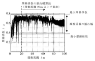
- This invention No. It is an example which shows the fluctuation width of the friction coefficient with respect to 1 sliding distance.
- Comparative Example No. 5 is an example showing a fluctuation width of a friction coefficient with respect to a sliding distance of 5.
- FIG. This invention No. 12 shows a sliding surface profile after a reciprocating sliding test in FIG. Comparative Example No. The sliding surface profile after the reciprocating sliding test in 21 is shown.
- the present inventors have laminated a compound containing a certain amount of chromium and a compound mainly composed of vanadium at a nano level by controlling individual film thicknesses, and further It has been found that a structure in which a thick film of vanadium-based compound is coated on the upper layer of the laminated film is effective. The details will be described below.
- a2 layers made of nitride are alternately stacked will be described.
- CrN widely applied to cutting tools and dies and chromium-based compounds such as CrAlN and CrSiN to which an effect element is added have excellent wear resistance and heat resistance.
- a1 layer made of a nitride, carbonitride, or oxynitride having a chromium content of 30% or more is applied to one of the laminated structures.
- the chromium content is less than this, the heat resistance and wear resistance are poor, and the sliding properties tend to deteriorate.
- vanadium is appropriately oxidized in the operating temperature range of 25 to 200 ° C., so that it is formed on the surface of the substrate as a thin oxide layer, and the counterpart material (workpiece) The affinity with the material is reduced. Therefore, the adhesion of the workpiece to the surface of the film during use can be reduced.
- the vanadium oxide reacts with the surface of the workpiece and the iron oxide that is the wear powder, and softens the iron oxide, so it is aggressive against the film. Is reduced.
- one of the laminated structures is made of nitride, carbonitride, or oxynitride having vanadium of 60% or more in terms of atomic ratio of the metal portion. Apply layer a2. More preferably, it is 70 atomic% or more, and further 80 atomic% or more. In terms of manufacturing cost, it is preferable to apply a vanadium nitride, carbonitride, or oxynitride formed using a simple metal target.
- the individual film thicknesses of these laminated films are set to 50 nm or less.
- a covering member having the above-mentioned various characteristics in a balanced manner is obtained.
- damage such as galling that occurs during sliding is suppressed, and the life of the member is increased. Can improve.
- the present invention is preferably applied to a plastic working mold in which the working surface of the mold is in an environment in which the work surface slides violently with the workpiece.
- More preferable individual film thickness is less than 30 nm, and further less than 10 nm.
- the individual film thickness of the laminated film can be adjusted by controlling the input power applied to the target, the chamber volume of the apparatus used for film formation, the table rotation speed, and the like.
- the film thickness of the a2 layer is made larger than the film thickness of the a1 layer in order to obtain sufficient sliding characteristics even under severe use environment. Furthermore, if it is 1.5 times or more, an oxide of vanadium that enhances sliding properties is sufficiently generated, which is more preferable. More preferably, it is 2.0 times or more. In addition, when the operating temperature range is approximately 300 ° C. or higher, the oxidation of the compound mainly composed of vanadium further proceeds, so excessive oxide is formed, and depending on the usage environment, the wear resistance may be reduced. There is. Therefore, the thickness of the a2 layer is preferably 4.0 times or less than the thickness of the a1 layer.
- the a1 layer and the a2 layer are preferably nitrides because they are more excellent in wear resistance and heat resistance.
- nitride is the main component, excellent wear resistance and heat resistance can be exhibited even if a part of the nitride contains carbide, oxide or the like.
- the thickness of the A layer is preferably 3 ⁇ m or more. More preferably, it is 5 ⁇ m or more.
- a hard film such as metal, carbide, carbonitride, or nitride may be coated between the base material and the A layer in order to ensure adhesion.
- the a1 layer preferably contains 10% or more of aluminum in terms of the atomic ratio of the metal portion. Furthermore, it is more preferable that it is 30 atomic% or more.
- the aluminum content is more preferably 70 atomic% or less, and even more preferably 65% atom or less.
- the a1 layer contains 1 to 10% of silicon in the atomic ratio of the metal portion because the hardness of the coating is improved and, for example, the wear resistance of the mold is further improved.
- the Vickers hardness of the A layer can be 2000 HV 10 or more. Furthermore, preferable because it is a 2500 HV 10 or more high hardness. If the silicon content is less than this, the hardness cannot be improved sufficiently. Moreover, when there is more content of a silicon than this, there exists a tendency for the toughness of a film to fall.
- the B layer composed of a nitride, carbonitride, or oxynitride mainly composed of vanadium which is the uppermost layer of the A layer, which is the most important feature of the present invention will be described.
- the compound mainly composed of vanadium is appropriately oxidized by the heat during sliding and functions as a lubricating layer. Therefore, a certain degree of sliding characteristics is ensured by mutually laminating the a1 layer having excellent wear resistance and heat resistance and the a2 layer having excellent sliding characteristics at the nano level.
- that alone does not provide sufficient familiarity between the mold and the workpiece in the initial stage of tool use, and sudden galling may occur in the initial stage.
- the vanadium oxide which is superior in lubrication effect, is provided by using a compound mainly composed of vanadium of 0.1 ⁇ m or more, which is thicker than the individual thickness of the laminated a2 layers, on the upper layer of the A layer. Since this is sufficiently generated from the initial stage, initial sudden galling is suppressed. More preferably, it is 0.2 ⁇ m or more. If it is thinner than this, the familiarity between the mold and the workpiece is not sufficient in the initial stage, and sudden galling is likely to occur. Further, in a complex-shaped mold, variations in film components and colors tend to occur at the mold site. If the film thickness becomes too thick, it takes time to form the film and the productivity is deteriorated.
- the film thickness of the B layer is preferably 8 ⁇ m or less. Further, depending on the use environment, the wear resistance of the entire coating film may be lowered, so that it is more preferably 5 ⁇ m or less. Furthermore, it is 3 ⁇ m or less.
- a nitride, carbonitride, or oxynitride having vanadium of 60% or more in the atomic ratio of the metal portion is applied to the B layer. More preferably, the vanadium content is 70 atomic% or more, and more preferably 80 atomic% or more. In terms of manufacturing cost, it is preferable to apply a vanadium nitride, carbonitride, or oxynitride formed using a simple metal target.
- the layer B is preferable because it is provided directly on the layer A because the coating structure becomes simple and the manufacture becomes easy.
- the B layer is preferably provided with a vanadium nitride having better wear resistance and heat resistance.
- nitride is the main component, excellent wear resistance and heat resistance can be exhibited even if a part thereof contains carbide, oxide or the like.
- the total film thickness of the A layer and the B layer is preferably 4 ⁇ m or more and 20 ⁇ m or less.
- the total film thickness of the A layer and the B layer is preferably 8 ⁇ m or more. Further, it is more preferably 10 ⁇ m or more.
- membrane peeling may become easy to generate
- the A layer is preferably thicker than the B layer.
- the surface roughness of the B layer is preferably Ra ⁇ 0.2 ⁇ m, Rz ⁇ 2.0 ⁇ m, and Rsk ⁇ 0. Since the surface of the hard coating contains droplets, coating defects, impurities, and the like and is not suitable for use as a mold, it is preferably smooth. In particular, when the film is thick, the surface roughness is lowered due to accumulation of droplets and film defects, so it is preferable to smooth the film surface. Under the sliding environment, the convex portion on the surface of the film is the starting point, attacking the workpiece, and generating abrasion powder, peeling of the film and wear occur.
- the surface roughness Rsk value (ISO4287-1997) is a parameter indicating the objectivity with respect to the center line of the amplitude distribution curve. For example, when the surface of the film has many concave portions, Rsk ⁇ 0 is indicated, and when there are many convex portions, Rsk> 0 is indicated, and the frequency of the convex portions and the concave portions can be managed. In the present invention, it is preferable that the number of convex portions is small, and it is preferable that Rsk ⁇ 0.
- the vanadium oxide formed on the surface of the substrate under the usage environment of the mold is uniformly formed from the initial stage, so that the sliding characteristics are improved. Therefore, it is preferable.
- the workpiece is iron-based, iron oxide adheres thinly and evenly over the entire film on the vanadium oxide, so the iron oxide itself is excellent due to improved sliding characteristics. This is preferable because it can exhibit sliding properties.
- the polishing method after coating is important.
- the conventional coating polishing methods such as polishing with abrasive paper and polishing with media consisting of resin and diamond particles can reduce the surface roughness, which is an indicator of Ra and Rz, but reduce the protrusions reliably. It is not easy.
- the base material of the present invention is not particularly defined, alloy tool steel for cold mold, alloy tool steel for hot mold, high speed tool steel, cemented carbide or the like can be used.
- the hard coating according to the present invention can be coated at a temperature lower than the tempering temperature of a base material such as cold die steel, hot die steel or high speed steel by coating with the PVD method. The fluctuation of the dimension of can be suppressed. Further, it is preferable because compressive residual stress can be applied to the hard coating and the mechanical properties of the hard coating can be improved.
- PVD methods it is preferable to coat with an arc ion plating method having excellent film adhesion.
- the substrate may be preliminarily applied with a surface hardening treatment using diffusion such as nitriding treatment or carburizing treatment.
- Example 1 the characteristics of the coating composition were evaluated by a ball-on-disk test.
- a disk-shaped test piece (diameter 20 mm ⁇ thickness 5 mm) of high-speed steel SKH51 specified by JIS was prepared as a treated substrate. This is tempered to 64 HRC by tempering at 560 ° C. after quenching by cooling with nitrogen gas from heating and holding at 1180 ° C. in vacuum. All the substrates were subjected to alkaline ultrasonic cleaning after mirror-mechanical polishing of the flat surface.
- the arc ion plating method was used as the film forming means.
- the film formation is performed using a PVD apparatus having a structure in which the substrate rotates around the center surrounded by a plurality of targets. Then, the substrate was placed on a plate having a rotating mechanism on a jig table having a planetary mechanism in the chamber. The table and the plate on the table rotate independently of each other.
- the sample was adjusted to a preferable surface roughness by buffing the surface after coating with a diamond paste having a particle size of 3 ⁇ m.
- the surface roughness value of each sample was measured using a stylus type roughness meter (SURFCOM 480A manufactured by Tokyo Seimitsu Co., Ltd.) under the conditions of an evaluation length of 4 mm, a measurement speed of 0.3 mm / s, and a cutoff value of 0.8 mm. Measured. Table 1 shows the coating composition and surface roughness.
- the total film thickness and the film thickness (layer B) of VN or VCN provided immediately above the mutual laminated film were measured with an optical microscope.
- the individual film thicknesses of the mutual laminated films were measured by electron microscope observation.
- Sample No. In each of 1-4, the film thickness of individual VN or VCN in the mutual laminated film was about 6 nm, and the film thickness of CrN or CrCN was about 3 nm.
- test conditions were as follows. Using a ball-on-disk tester (Tribometer manufactured by CSM Instruments), pressing SUJ2 balls (6 mm in diameter) with a load of 10 N against the coating film in the air at 25 ° C (room temperature) to 400 ° C. The disc-shaped test piece was rotated at a speed of 150 mm / sec, and the test distance was 100 m.
- membrane sliding part was measured on the conditions of 1.5 mm / s with the surface roughness meter (Surfcom 480A by Tokyo Seimitsu Co., Ltd.), and the abrasion state was evaluated.
- the difference between the maximum friction coefficient and the minimum friction coefficient during the test was measured using the fluctuation width of the friction coefficient during the measurement as an index.
- a sample having a large coefficient of friction fluctuation with respect to the sliding distance means that the sliding resistance is high, and chattering occurs during sliding.
- the fluctuation width of the friction coefficient with respect to the sliding distance was calculated between the test distances of 20 m to 100 m where the friction coefficient was stable. In FIGS. An example of the wear coefficient fluctuation width of 1 and 5 is shown. Table 2 shows the test results.
- Nos. 1 to 3 are sample Nos. Having no VN or VCN immediately above the mutual laminated film. 4 shows a smaller sliding width of the wear coefficient with respect to the sliding distance during sliding from room temperature to 400 ° C., no chattering, and excellent sliding characteristics.
- the sample No. 1 has a thick VN film directly above the mutual laminated film.
- No. 5 does not include VN or VCN, which has excellent sliding characteristics, and therefore the friction coefficient fluctuation width with respect to the sliding distance is large, and the sliding characteristics are poor.
- Example 2 in order to evaluate in a harsher test environment, the total film thickness of the film was set to be thin, and the characteristics of the film composition in the reciprocating friction and wear test in which the load applied to the hard film was larger. evaluated.
- a square test piece 180 mm ⁇ 20 mm ⁇ 20 mm
- the film formation time was adjusted so that the total film thickness was 4.0 and 4.5 ⁇ m, and other conditions were the same as in Example 1.
- the sample was adjusted to a preferable surface roughness by buffing the surface after coating with a diamond paste having a particle size of 3 ⁇ m.
- the film surface roughness value of each sample was measured by the same method as in Example 1. Table 3 shows the coating composition and surface roughness.
- the film thickness was measured in the same manner as in Example 1. Sample No. In each of 6 to 8, the film thickness of each VN in the laminated film was about 6 nm, and the film thickness of CrN was about 3 nm.
- a reciprocating frictional wear test was performed on the inventive example and a comparative example in which the VN film was not provided immediately above the mutual laminated film.
- the film was formed under the same conditions as in Example 1 except that the film formation time was adjusted so that the total film thickness was 10 ⁇ m.
- the surface was smoothed with a commonly used aero wrap (aero wrap is a registered trademark of Yamashita Towers Co., Ltd.).
- Table 5 shows the coating composition and surface roughness. The surface roughness and film thickness were measured in the same manner as in Example 1. Sample No. 10 and 11, the film thickness of each VN in the laminated film was about 6 nm, and the film thickness of CrN was about 3 nm.
- Each sample was adjusted to have a preferable surface roughness by buffing using a diamond paste having a particle size of 3 ⁇ m so as to obtain a preferable surface state.
- Table 7 shows the coating composition and surface roughness. The surface roughness and film thickness were measured in the same manner as in Example 1. Sample No. with different deposition conditions In No. 19, the film thicknesses of individual VN and CrN in the mutual laminated film were the same at about 4 nm. In other samples, the film thickness of each VN in the mutual laminated film was about 6 nm, and the other film thickness was about 3 nm.
- Sample No. which is a preferable surface state of the present invention Nos. 12 to 17 were excellent in sliding characteristics because no scratch marks or galling occurred on the sliding surface after the sliding test.
- Sample No. No. 18 is a thin VN film immediately above the mutual laminated film. Therefore, although the surface state of the film is preferable, the familiarity at the initial stage is not sufficient. The sliding characteristics were worse than those of 12 to 17, and scratch marks were observed.
- Sample No. No. 19 has the same individual film thickness of the mutual laminated film of CrN and VN. For this reason, a scratch mark was observed because an oxide of vanadium that enhances the sliding characteristics was not sufficiently generated.
- Sample No. No. 20 does not have a thick VN film immediately above the mutual laminated film.
- Sample No. 21 is a single layer film of CrN and does not contain a VN layer. Therefore, although it was a preferable surface state, the sliding characteristic was bad and the scratch mark was formed deeply.
- Sample No. 22 and 23 are mutual laminated films of TiAlN and VN not containing chromium. Therefore, even when a thick VN film was provided immediately above the mutual laminated film, the heat resistance was poor compared to a nitride containing a certain amount of chromium, and scratch marks were formed deeply.
- the sample No. used in Example 4 was measured.
- the hardness was measured by the load of 10 gf from the membrane
- HM100 Vickers hardness tester
- the addition of other elements to CrN has higher hardness and better wear resistance than CrN and VN.
- the hardness of the A layer was a high hardness of 2500 HV or more.
- the test results are shown in Table 9.
- the covering member of the present invention has excellent sliding characteristics, it can be used for plastic working dies such as press working and forging dies used from cold to hot. Further, the present invention can be applied to a die-casting pin, an insert, and a sliding part constituting various machines.
Landscapes
- Chemical & Material Sciences (AREA)
- Engineering & Computer Science (AREA)
- Mechanical Engineering (AREA)
- Organic Chemistry (AREA)
- Materials Engineering (AREA)
- Metallurgy (AREA)
- Chemical Kinetics & Catalysis (AREA)
- Inorganic Chemistry (AREA)
- Ceramic Engineering (AREA)
- Physical Vapour Deposition (AREA)
- Other Surface Treatments For Metallic Materials (AREA)
- Sliding-Contact Bearings (AREA)
- Mounting, Exchange, And Manufacturing Of Dies (AREA)
- Forging (AREA)
Abstract
Description
そして、被加工材の高強度化、加工製品の高精度化、成形サイクルの高速化が進む塑性加工用金型では、その作業面への負荷が特に増大していることから、作業面に硬質皮膜を形成した被覆金型が多用されており、特に冷間加工用は高硬度でかつ摩擦係数の低いTiCNやTiCが使用されている。
一方、切削工具の分野では、CrNと、耐摩耗性と耐熱性に優れる周期律表の4a、5a、6a族元素、AlおよびSiから選択された少なくとも1種の元素の窒化物を積層した硬質皮膜(特許文献3)が開示されている。
更には、切削工具および摺動部材に適した硬質皮膜として、クロム系の窒化物とVNとを交互に積層した硬質皮膜(特許文献4)が開示されている。
該A層の上層にあって金属部分の原子比率でバナジウムが60%以上の窒化物、炭窒化物または酸窒化物からなるB層を含み、
前記A層は、個々のa1層およびa2層の膜厚が50nm以下であり、かつ、a2層の膜厚の方がa1層の膜厚よりも厚く、
前記B層は、膜厚が0.1μm以上である摺動特性に優れた被覆部材である。
また、A層とB層の総膜厚は、4μm以上20μm以下であることが好ましい。更には、A層とB層の総膜厚は、8μm以上であることが好ましい。
また、B層は、表面粗さがRa<0.2μm、Rz<2.0μm、Rsk<0であることが好ましい。
また、B層は、膜厚が0.2μm以上であることが好ましい。更には、B層は、膜厚が8μm以下であることが好ましい。
また、a1層が、金属部分の原子比率でアルミニウムを10%以上含むことが好ましい。
また、a1層が、金属(半金属を含む)部分の原子比率でシリコンを1~10%含むことが好ましい。
また、被覆部材は、金型であることが好ましい。
従来から切削工具や金型へ広く適用されているCrNやこれに効果元素を添加したCrAlN、CrSiN等のクロム系の化合物は、耐摩耗性と耐熱性に優れるものである。
特に、摺動中に摩擦熱が発生する高負荷環境で使用される金型においては、クロムを一定量含有する皮膜を適用することが、部材の寿命向上に有効である。本発明では、耐熱性と耐摩耗性を両立するために、積層構造の一方に、金属部分の原子比率でクロムが30%以上の窒化物、炭窒化物または酸窒化物からなるa1層を適用する。クロムの含有量がこれよりも少ないと耐熱性および耐摩耗性が乏しく、また、摺動特性が低下する傾向にある。
製造コストの点では、単純な金属ターゲットを使用して成膜するクロムの窒化物、炭窒化物または酸窒化物を適用することが好ましい。
また、バナジウムの酸化物が被加工材の鉄酸化物を軟化させる効果は、摺動中に摩耗粉の発生を抑制する傾向にあり、プレス成型中の作業面にて局部的なスクラッチやカジリを抑えることができる。
本発明では、摺動特性が優れるバナジウムの酸化物を十分に発生させるため、積層構造の一方に、金属部分の原子比率でバナジウムが60%以上の窒化物、炭窒化物または酸窒化物からなるa2層を適用する。より好ましくは70原子%以上、更には80原子%以上である。
製造コストの点では、単純な金属ターゲットを使用して成膜するバナジウムの窒化物、炭窒化物または酸窒化物を適用することが好ましい。
積層皮膜の個々の膜厚は、ターゲットに印加する投入電力、成膜に用いる装置のチャンバー容積およびテーブル回転数等を制御することで調整することができる。
また、概ね300℃以上の使用温度域になると、バナジウムを主体とする化合物の酸化が更に進行することから、過剰な酸化物が形成されるため、使用環境によっては、耐摩耗性が低下する場合がある。そのため、a2層の膜厚は、a1層の膜厚の4.0倍以下とすることが好ましい。
a1層およびa2層は、窒化物である方が耐摩耗性と耐熱性がより優れるため好ましい。また、窒化物が主体であればその一部に炭化物、酸化物等を含有しても優れた耐摩耗性と耐熱性を発揮することができる。
基材とA層の間には、密着性を確保するために、金属、炭化物、炭窒化物または窒化物等の硬質皮膜を被覆してもよい。
a1層がシリコンを含有することで、A層のビッカース硬度を2000HV10以上にすることができる。更には、2500HV10以上の高硬度とすることができるので好ましい。
シリコンの含有量がこれよりも少ないと、硬度の向上が十分でない。また、シリコンの含有量がこれよりも多いと皮膜の靭性が低下する傾向にある。
上記の通り、バナジウムを主体とする化合物は、摺動中の熱によって、適度に酸化し、潤滑層として働く。そのため、耐摩耗性と耐熱性に優れるa1層と摺動特性に優れるa2層をナノレベルで相互積層させることで、ある程度の摺動特性は確保される。しかし、それだけでは、工具使用における初期段階での金型とワークの馴染みが十分でなく、初期段階で突発的なカジリが発生する場合がある。
そこで、相互積層したa2層の個々の膜厚よりも厚い、0.1μm以上のバナジウムが主体の化合物をA層の上層に設けることで、潤滑効果が優れるバナジウムの酸化物が、金型使用時の初期から十分に生成されるため、初期の突発的なカジリが抑制される。より好ましくは0.2μm以上である。
これよりも薄い場合には、初期段階において金型と被加工材の馴染みが十分でなく、突発的なカジリが発生し易い。また、複雑形状の金型では、金型部位において皮膜成分や色味にバラツキが生じやすい。膜厚が厚くなり過ぎると、成膜に時間がかかり生産性が悪くなるので、B層の膜厚は、8μm以下であることが好ましい。また、使用環境によっては、皮膜全体の耐摩耗性が低下する場合があるため、より好ましくは5μm以下である。更には、3μm以下である。
本発明では、摺動特性が優れるバナジウムの酸化物を十分に発生させるため、B層は、金属部分の原子比率でバナジウムが60%以上の窒化物、炭窒化物または酸窒化物を適用する。バナジウムの含有量を70原子%以上、更には、80原子%以上とすることがより好ましい。
製造コストの点では、単純な金属ターゲットを使用して成膜するバナジウムの窒化物、炭窒化物または酸窒化物を適用することが好ましい。
B層は、耐摩耗性と耐熱性がより優れるバナジウムの窒化物を設けることが好ましい。また、窒化物が主体であれば、その一部に炭化物、酸化物等を含有しても優れた耐摩耗性と耐熱性を発揮することができる。
例えば、プレス成形に用いる金型では、皮膜表面から加えられる力が大きいため、皮膜がこれよりも薄くなると皮膜強度が乏しくなり、皮膜が損傷し易くなる。特に、高負荷環境下では、皮膜と基材の界面に大きな力が加わるため、皮膜と基材の弾性変形量の違いから、皮膜剥離や皮膜損傷が発生し易く、金型寿命に及ぼす膜厚の影響が大きくなる。
高負荷環境下においては、A層とB層の総膜厚が8μm以上であることが好ましい。更には、10μm以上であることがより好ましい。
また、硬質皮膜の総膜厚が厚くなり過ぎると、皮膜剥離が発生し易くなる場合があり、総膜厚は15μm以下であることが好ましい。また、A層はB層よりも厚膜であることが好ましい。
硬質皮膜の表面には、ドロップレットや皮膜欠陥、不純物等が含まれ、金型として使用するのに適切で無いため、平滑にすることが好ましい。特に、厚膜になると、ドロップレットや皮膜欠陥が蓄積することで表面粗さが低下するので、皮膜表面を平滑にすることが好ましい。
そして、摺動環境下では、皮膜表面の凸部が起点となり、被加工材を攻撃し、摩耗粉を発生させることにより、皮膜剥離や摩耗が発生する。
そのため、一般的な表面粗さであるRa、Rz(ISO4287-1997)に加えては、凸部の頻度を把握するためにRskを制御することが好ましい。
表面粗さRsk値(ISO4287-1997)は、振幅分布曲線の中心線に対する対象性を示すパラメーターである。例えば、表面に凹部が多い皮膜表面の場合は、Rsk<0を示し、凸部が多い場合にはRsk>0を示し、凸部と凹部の頻度を管理することが可能である。本発明では、凸部が少ないことが好ましく、Rsk<0とすることが好ましい。
そして、表面粗さを上記の範囲に制御することで、金型の使用環境下で基材表面に形成されるバナジウムの酸化物が初期段階から均等に成形されるため、摺動特性が向上するので好ましい。特に、被加工材が鉄系である場合には、バナジウムの酸化物上に鉄酸化物が皮膜全体に薄く均一に付着するので、鉄酸化物自体も摺動特性の向上に起因して優れた摺動特性を発揮することができるので好ましい。
また、本発明に係る硬質皮膜は、PVD法で被覆することで、冷間ダイス鋼、熱間ダイス鋼または高速度鋼等の基材の焼き戻し温度より低温で被覆処理が可能となり、基材の寸法の変動を抑制することができる。また、硬質皮膜に圧縮残留応力を付与することができ、硬質皮膜の機械特性も改善できるので好ましい。PVD法の中でも皮膜密着性が優れるアークイオンプレーティング法で被覆することが好ましい。
基材は、窒化処理または浸炭処理等といった拡散を利用した表面硬化処理を予め適用してもよい。
処理基材には、JISに規定される高速度鋼SKH51の円盤状試験片(直径20mm×厚さ5mm)を準備した。これは、真空中1180℃の加熱保持より窒素ガス冷却により焼入れ後、560℃での焼戻しにより64HRCに調質したものである。いずれの基材も、平面を鏡面機械研磨した後、アルカリ超音波洗浄を行った。
そして装置内に反応ガスを導入し、各種ターゲット上にアーク放電を発生させて、723Kのもとでコーティングを行った。
試料No.1~4は、CrターゲットとVターゲットを用い、Crターゲットに印加する投入電流を100A、Vターゲットに印加する投入電流を150A、反応ガス圧力は3Pa、テーブル回転数は3rpm、反応ガスはN、コーティング時の基材には-100Vのバイアス電圧を印加して成膜した。また、試料No.3は、反応ガスにNとメタンを使用して成膜した。
各試料の総膜厚が10μmになるよう成膜時間を調整した。試料No.5はCrターゲットのみを用い、投入電流150Aで成膜した。
各試料の皮膜表面粗さ値は、触針式粗さ計(株式会社東京精密製 SURFCOM480A)を使用し、評価長さ4mm、測定速度0.3mm/s、カットオフ値0.8mmの条件にて測定した。表1に皮膜構成と表面粗さを示す。
試料No.1~4ともに相互積層皮膜における個々のVNまたはVCNの膜厚は約6nm、CrNまたはCrCNの膜厚は約3nmであった。

摺動特性については、測定中の摩擦係数の振れ幅を指標とし、試験中の最大摩擦係数と最小摩擦係数の差を測定した。摺動距離に対する摩擦係数振れ幅が大きい試料は、摺動抵抗が高いことを意味しており、摺動中にビビリが発生する。なお、摺動距離に対する摩擦係数の振れ幅は、摩擦係数が安定する20m~100mの試験距離間で算出した。図1、2に試料No.1、5の摩耗係数振れ幅の一例を示す。表2に試験結果を示す。

単層のCrNである試料No.5は、摺動特性が優れるVNまたはVCNを含まないため、摺動距離に対する摩擦係数振れ幅が大きくなり、摺動特性が乏しかった。
表面処理を行う基材は、JISに規定されるダイス鋼SKD61の角状試験片(180mm×20mm×20mm)を準備した。これは、真空中1050℃の加熱保持より窒素ガス冷却により焼入れ後、560℃での焼戻しにより45HRCに調質した。これらの平面を鏡面機械研磨した後、アルカリ超音波洗浄を行った。
膜厚の測定は、実施例1と同様に測定した。試料No.6~8ともに相互積層皮膜における個々のVNの膜厚は約6nm、CrNの膜厚は約3nmであった。

本発明例のNo.7と比較例のNo.8、9の比較では、CrNとVNの相互積層皮膜の直上に厚膜のVN膜を設けることで、基材が露出するまでの往復回数が伸びたことが確認される。
実施例1、2のボールオンディスク試験および往復動摩擦摩耗試験いずれでも、本発明の皮膜構造が優れた摺動特性を示すことが確認された。
また、本発明例のNo.6、7の比較から、総膜厚を厚くすることで、基材露出までの往復回数が改善されることが確認された。

表面の平滑化には、通常使用されるエアロラップ(エアロラップは株式会社ヤマシタワークスの登録商標である)で平滑化した。表5に皮膜構成と表面粗さを示す。表面粗さと膜厚の測定は、実施例1と同様に測定した。
試料No.10、11ともに相互積層皮膜における個々のVNの膜厚は約6nm、CrNの膜厚は約3nmであった。

往復摩擦摩耗試験の回数を200往復まで行い、試験後の皮膜表面のスクラッチ痕の深さを、レーザー顕微鏡(株式会社キーエンス:VK-8710)を用いて、スクラッチ痕部を200倍で観察し、その表面プロファイル測定から算出した。表6に試験結果を示す。
各試料とも、膜厚が10μmと厚いため、200往復でも試験途中でカジリは発生しなかった。CrNとVNの相互積層皮膜の直上に厚膜のVN膜を設けることで、表面粗さのRskがプラス側であっても、摺動試験後のスクラッチ痕深さが小さくなることが確認された。

なお、試料No.19は、A層の個々の膜厚比を変化させるため、Crターゲット上に印加する投入電流を150A、Vターゲット上に印加する投入電流を100Aとして成膜した。
AlCrSiNの成膜には、Al60Cr37Si3ターゲットを使用した(数値は原子比、以下同様)。
CrSiBNの成膜には、Cr92Si3B5ターゲットを使用した。
TiAlNの成膜には、Ti50Al50のターゲットを使用した。TiNの成膜には、Tiターゲットを使用した。
各試料好ましい表面状態になるように、粒径3μmのダイヤモンドペーストを用いたバフ研磨にて好ましい表面粗さに調整した。
表7に皮膜構成と表面粗さを示す。表面粗さと膜厚の測定は、実施例1と同様に測定した。
成膜条件を変えた試料No.19では、相互積層皮膜における個々のVNとCrNの膜厚は約4nmで同じであった。その他の試料は、相互積層皮膜における個々のVNの膜厚は約6nm、もう一方の膜厚は約3nmであった。

往復摩擦摩耗試験の回数を200往復まで行い、試験後の皮膜表面のスクラッチ痕の深さを、レーザー顕微鏡(株式会社キーエンス:VK-8710)を用いて、スクラッチ痕部を200倍で観察し、その表面プロファイル測定から算出した。表8に試験結果を示す。
また、図3、4に試料No.12と試料No.21のそれぞれの表面プロファイルを示す。

試料No.18は、相互積層皮膜の直上にあるVN膜が薄い。そのため、皮膜の表面状態が好ましいにも関わらず、初期での馴染み性が十分でなく、試料No.12~17に比べて摺動特性が悪く、スクラッチ痕跡が観察された。
試料No.19は、CrNとVNの相互積層皮膜の個々の膜厚が同じである。そのため、摺動特性を高めるバナジウムの酸化物が十分に生成されないため、スクラッチ痕が観察された。
試料No.20は、相互積層皮膜の直上に厚いVN膜を設けていない。そのため、皮膜の表面状態が好ましいにも関わらず、初期での馴染み性が悪く、試料No.12~17に比べて摺動特性が悪く、スクラッチ痕が観察された。
試料No.21は、CrNの単層膜で、VN層を含有しない。そのため、好ましい表面状態であるが摺動特性が悪く、スクラッチ痕が深く形成された。
試料No.22、23は、クロムを含有しないTiAlNとVNの相互積層皮膜である。そのため、相互積層皮膜の直上に厚いVN膜を設けても、クロムを一定量含有する窒化物に比べて耐熱性に乏しく、スクラッチ痕が深く形成された。
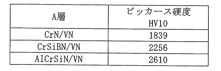
CrNとVNの相互積層皮膜よりも、CrNに他元素を添加した方が相互積層皮膜の硬度が高く耐摩耗性により優れる。特に、AlとSiを同時添加したAlCrSiNでは、A層の硬度が2500HV以上の高硬度であった。試験結果を表9に示す。
Claims (11)
- 作業面に硬質皮膜を有する被覆部材であって、前記硬質皮膜は金属(半金属を含む。以下同様)部分の原子比率でクロムが30%以上の窒化物、炭窒化物または酸窒化物からなるa1層と、金属部分の原子比率でバナジウムが60%以上の窒化物、炭窒化物または酸窒化物からなるa2層とが交互に積層したA層と、
該A層の上層にあって金属部分の原子比率でバナジウムが60%以上の窒化物、炭窒化物または酸窒化物からなるB層を含み、
前記A層は、個々のa1層およびa2層の膜厚が50nm以下であり、かつ、a2層の膜厚の方がa1層の膜厚よりも厚く、
前記B層は、膜厚が0.1μm以上であることを特徴とする摺動特性に優れた被覆部材。 - a2層の膜厚が、a1層の膜厚よりも1.5倍以上であることを特徴とする請求項1に記載の摺動特性に優れた被覆部材。
- a2層の膜厚が、a1層の膜厚よりも2.0倍以上4.0倍以下であることを特徴とする請求項2に記載の摺動特性に優れた被覆部材。
- A層とB層の総膜厚は、4μm以上20μm以下であることを特徴とする請求項1ないし3のいずれかに記載の摺動特性に優れた被覆部材。
- A層とB層の総膜厚は、8μm以上であることを特徴とする請求項4に記載の摺動特性に優れた被覆部材。
- B層は、表面粗さがRa<0.2μm、Rz<2.0μm、Rsk<0であることを特徴とする請求項1ないし5のいずれかに記載の摺動特性に優れた被覆部材。
- B層は、膜厚が0.2μm以上であることを特徴とする請求項1ないし6のいずれかに記載の摺動特性に優れた被覆部材。
- B層は、膜厚が8μm以下であることを特徴とする請求項1ないし7のいずれかに記載の摺動特性に優れた被覆部材。
- a1層が、金属部分の原子比率でアルミニウムを10%以上含むことを特徴とする請求項1ないし8のいずれかに記載の摺動特性に優れた被覆部材。
- a1層が、金属(半金属を含む)部分の原子比率でシリコンを1~10%含むことを特徴とする請求項1ないし9のいずれかに記載の摺動特性に優れた被覆部材。
- 被覆部材は、金型であることを特徴とする請求項1ないし10のいずれかに記載の摺動特性に優れた被覆部材。
Priority Applications (5)
| Application Number | Priority Date | Filing Date | Title |
|---|---|---|---|
| EP12835242.4A EP2762248B1 (en) | 2011-09-28 | 2012-09-26 | Covered member with excellent sliding properties |
| US14/241,614 US9604275B2 (en) | 2011-09-28 | 2012-09-26 | Covering member with excellent sliding properties |
| ES12835242.4T ES2677711T3 (es) | 2011-09-28 | 2012-09-26 | Elemento recubierto con excelentes propiedades de deslizamiento |
| CN201280046447.1A CN103826773B (zh) | 2011-09-28 | 2012-09-26 | 滑动特性优异的被覆构件 |
| JP2013536316A JP6015663B2 (ja) | 2011-09-28 | 2012-09-26 | 摺動特性に優れた被覆部材 |
Applications Claiming Priority (4)
| Application Number | Priority Date | Filing Date | Title |
|---|---|---|---|
| JP2011-211963 | 2011-09-28 | ||
| JP2011211963 | 2011-09-28 | ||
| JP2012071223 | 2012-03-27 | ||
| JP2012-071223 | 2012-03-27 |
Publications (1)
| Publication Number | Publication Date |
|---|---|
| WO2013047548A1 true WO2013047548A1 (ja) | 2013-04-04 |
Family
ID=47995579
Family Applications (1)
| Application Number | Title | Priority Date | Filing Date |
|---|---|---|---|
| PCT/JP2012/074627 Ceased WO2013047548A1 (ja) | 2011-09-28 | 2012-09-26 | 摺動特性に優れた被覆部材 |
Country Status (6)
| Country | Link |
|---|---|
| US (1) | US9604275B2 (ja) |
| EP (1) | EP2762248B1 (ja) |
| JP (1) | JP6015663B2 (ja) |
| CN (1) | CN103826773B (ja) |
| ES (1) | ES2677711T3 (ja) |
| WO (1) | WO2013047548A1 (ja) |
Cited By (8)
| Publication number | Priority date | Publication date | Assignee | Title |
|---|---|---|---|---|
| JP2014200831A (ja) * | 2013-04-08 | 2014-10-27 | 株式会社神戸製鋼所 | 冷間成形金型の異常検出方法 |
| WO2017078138A1 (ja) * | 2015-11-05 | 2017-05-11 | フジタ技研株式会社 | 被覆部材、表面被覆金型、及び成膜方法 |
| EP3135411A4 (en) * | 2014-04-25 | 2017-11-01 | Kabushiki Kaisha Kobe Seiko Sho (Kobe Steel, Ltd.) | Cutting tool |
| CN107532279A (zh) * | 2015-04-23 | 2018-01-02 | 日立金属株式会社 | 包覆模具及其制造方法 |
| WO2020116291A1 (ja) * | 2018-12-03 | 2020-06-11 | 日立金属株式会社 | ホットスタンプ用被覆金型 |
| KR20210124463A (ko) | 2019-03-20 | 2021-10-14 | 히다찌긴조꾸가부시끼가이사 | 피복 금형, 피복 금형의 제조 방법 및 경질 피막 형성용 타깃 |
| JP2022518955A (ja) * | 2019-02-01 | 2022-03-17 | エリコン サーフェス ソリューションズ アーゲー、 プフェフィコン | コーティングされた及びコーティングされていない超高強度鋼板のプレス硬化用の高性能工具コーティング |
| WO2023234362A1 (ja) * | 2022-06-01 | 2023-12-07 | パーカー加工株式会社 | 摺動部材 |
Families Citing this family (6)
| Publication number | Priority date | Publication date | Assignee | Title |
|---|---|---|---|---|
| JP6392060B2 (ja) * | 2014-10-01 | 2018-09-19 | イチカワ株式会社 | 湿紙搬送ベルト、抄紙システム、抄紙方法および湿紙搬送ベルトの製造方法 |
| US10030773B2 (en) | 2016-03-04 | 2018-07-24 | Mahle International Gmbh | Piston ring |
| EP3760757A4 (en) * | 2018-02-27 | 2021-12-01 | Hitachi Metals, Ltd. | COATING ELEMENT AND ITS MANUFACTURING PROCESS |
| JP2019171512A (ja) * | 2018-03-28 | 2019-10-10 | トヨタ自動車東日本株式会社 | 摺動部材及びその製造方法 |
| CN109252140A (zh) * | 2018-10-19 | 2019-01-22 | 扬州大学 | 一种冷作模具钢表面制备AlCrCN涂层的方法 |
| CA3230365A1 (en) * | 2021-09-23 | 2023-03-30 | Thomas GLECHNER | Coated article with enhanced oxidation resistance properties |
Citations (7)
| Publication number | Priority date | Publication date | Assignee | Title |
|---|---|---|---|---|
| JP2001310202A (ja) * | 2000-04-27 | 2001-11-06 | Mitsubishi Materials Corp | 硬質被覆層がすぐれた耐チッピング性を発揮する表面被覆サーメット製切削工具 |
| JP2003321764A (ja) | 2002-05-01 | 2003-11-14 | Mitsubishi Heavy Ind Ltd | 耐高温酸化に優れた高耐摩耗性・高硬度皮膜 |
| JP2005042146A (ja) | 2003-07-25 | 2005-02-17 | Mitsubishi Heavy Ind Ltd | 高耐摩耗性高硬度皮膜 |
| JP2005256081A (ja) | 2004-03-11 | 2005-09-22 | Kobe Steel Ltd | 硬質積層皮膜および硬質積層皮膜の形成方法 |
| JP2007111815A (ja) | 2005-10-19 | 2007-05-10 | Sumitomo Electric Hardmetal Corp | 表面被覆切削工具 |
| JP2008188738A (ja) * | 2007-02-06 | 2008-08-21 | Mitsubishi Materials Corp | 難削材の重切削加工で硬質被覆層がすぐれた耐チッピング性を発揮する表面被覆切削工具 |
| JP2011183545A (ja) | 2010-02-10 | 2011-09-22 | Hitachi Tool Engineering Ltd | 摺動特性に優れた被覆工具及びその製造方法 |
Family Cites Families (8)
| Publication number | Priority date | Publication date | Assignee | Title |
|---|---|---|---|---|
| JP3996809B2 (ja) | 2002-07-11 | 2007-10-24 | 住友電工ハードメタル株式会社 | 被覆切削工具 |
| JP4513058B2 (ja) * | 2004-08-10 | 2010-07-28 | 日立金属株式会社 | 鋳造用部材 |
| SE0402180D0 (sv) * | 2004-09-10 | 2004-09-10 | Sandvik Ab | Deposition of Ti1-xAlxN using Bipolar Pulsed Dual Magnetron Sputtering |
| WO2006070509A1 (ja) | 2004-12-28 | 2006-07-06 | Sumitomo Electric Hardmetal Corp. | 表面被覆切削工具および表面被覆切削工具の製造方法 |
| US7537822B2 (en) | 2005-05-26 | 2009-05-26 | Hitachi Tool Engineering, Ltd. | Hard-coated member |
| JP2009039838A (ja) * | 2007-08-10 | 2009-02-26 | Mitsubishi Materials Corp | 表面被覆切削工具 |
| JP4413958B2 (ja) | 2007-08-31 | 2010-02-10 | ユニオンツール株式会社 | 切削工具用硬質皮膜 |
| JP5245174B2 (ja) * | 2008-11-14 | 2013-07-24 | 住友電工ハードメタル株式会社 | 表面被覆切削工具 |
-
2012
- 2012-09-26 US US14/241,614 patent/US9604275B2/en active Active
- 2012-09-26 WO PCT/JP2012/074627 patent/WO2013047548A1/ja not_active Ceased
- 2012-09-26 CN CN201280046447.1A patent/CN103826773B/zh active Active
- 2012-09-26 EP EP12835242.4A patent/EP2762248B1/en active Active
- 2012-09-26 ES ES12835242.4T patent/ES2677711T3/es active Active
- 2012-09-26 JP JP2013536316A patent/JP6015663B2/ja active Active
Patent Citations (7)
| Publication number | Priority date | Publication date | Assignee | Title |
|---|---|---|---|---|
| JP2001310202A (ja) * | 2000-04-27 | 2001-11-06 | Mitsubishi Materials Corp | 硬質被覆層がすぐれた耐チッピング性を発揮する表面被覆サーメット製切削工具 |
| JP2003321764A (ja) | 2002-05-01 | 2003-11-14 | Mitsubishi Heavy Ind Ltd | 耐高温酸化に優れた高耐摩耗性・高硬度皮膜 |
| JP2005042146A (ja) | 2003-07-25 | 2005-02-17 | Mitsubishi Heavy Ind Ltd | 高耐摩耗性高硬度皮膜 |
| JP2005256081A (ja) | 2004-03-11 | 2005-09-22 | Kobe Steel Ltd | 硬質積層皮膜および硬質積層皮膜の形成方法 |
| JP2007111815A (ja) | 2005-10-19 | 2007-05-10 | Sumitomo Electric Hardmetal Corp | 表面被覆切削工具 |
| JP2008188738A (ja) * | 2007-02-06 | 2008-08-21 | Mitsubishi Materials Corp | 難削材の重切削加工で硬質被覆層がすぐれた耐チッピング性を発揮する表面被覆切削工具 |
| JP2011183545A (ja) | 2010-02-10 | 2011-09-22 | Hitachi Tool Engineering Ltd | 摺動特性に優れた被覆工具及びその製造方法 |
Cited By (17)
| Publication number | Priority date | Publication date | Assignee | Title |
|---|---|---|---|---|
| JP2014200831A (ja) * | 2013-04-08 | 2014-10-27 | 株式会社神戸製鋼所 | 冷間成形金型の異常検出方法 |
| EP3135411A4 (en) * | 2014-04-25 | 2017-11-01 | Kabushiki Kaisha Kobe Seiko Sho (Kobe Steel, Ltd.) | Cutting tool |
| CN107532279A (zh) * | 2015-04-23 | 2018-01-02 | 日立金属株式会社 | 包覆模具及其制造方法 |
| US11779989B2 (en) | 2015-04-23 | 2023-10-10 | Proterial, Ltd. | Coated metal mold and method for manufacturing same |
| WO2017078138A1 (ja) * | 2015-11-05 | 2017-05-11 | フジタ技研株式会社 | 被覆部材、表面被覆金型、及び成膜方法 |
| JPWO2017078138A1 (ja) * | 2015-11-05 | 2018-11-29 | フジタ技研株式会社 | 被覆部材、表面被覆金型、及び成膜方法 |
| JPWO2020116291A1 (ja) * | 2018-12-03 | 2021-10-21 | 日立金属株式会社 | ホットスタンプ用被覆金型 |
| KR20210084598A (ko) | 2018-12-03 | 2021-07-07 | 히다찌긴조꾸가부시끼가이사 | 핫스탬핑용 피복 금형 |
| KR102460884B1 (ko) | 2018-12-03 | 2022-10-31 | 히다찌긴조꾸가부시끼가이사 | 핫스탬핑용 피복 금형 |
| WO2020116291A1 (ja) * | 2018-12-03 | 2020-06-11 | 日立金属株式会社 | ホットスタンプ用被覆金型 |
| US12263513B2 (en) | 2018-12-03 | 2025-04-01 | Proterial, Ltd. | Coated die for use in hot stamping |
| JP2022518955A (ja) * | 2019-02-01 | 2022-03-17 | エリコン サーフェス ソリューションズ アーゲー、 プフェフィコン | コーティングされた及びコーティングされていない超高強度鋼板のプレス硬化用の高性能工具コーティング |
| JP7635713B2 (ja) | 2019-02-01 | 2025-02-26 | エリコン サーフェス ソリューションズ アーゲー、 プフェフィコン | コーティングされた又はコーティングされていない金属板のホットスタンピングのためのコーティングされた工具、及びその製造方法 |
| KR20210124463A (ko) | 2019-03-20 | 2021-10-14 | 히다찌긴조꾸가부시끼가이사 | 피복 금형, 피복 금형의 제조 방법 및 경질 피막 형성용 타깃 |
| KR20230170147A (ko) | 2019-03-20 | 2023-12-18 | 가부시키가이샤 프로테리아루 | 피복 금형, 피복 금형의 제조 방법 및 경질 피막 형성용 타깃 |
| US12163214B2 (en) | 2019-03-20 | 2024-12-10 | Proterial, Ltd. | Coated mold, method for manufacturing coated mold, and hard coat-forming target |
| WO2023234362A1 (ja) * | 2022-06-01 | 2023-12-07 | パーカー加工株式会社 | 摺動部材 |
Also Published As
| Publication number | Publication date |
|---|---|
| US20140234582A1 (en) | 2014-08-21 |
| CN103826773B (zh) | 2016-04-27 |
| ES2677711T3 (es) | 2018-08-06 |
| EP2762248A1 (en) | 2014-08-06 |
| CN103826773A (zh) | 2014-05-28 |
| EP2762248B1 (en) | 2018-06-13 |
| US9604275B2 (en) | 2017-03-28 |
| JPWO2013047548A1 (ja) | 2015-03-26 |
| EP2762248A4 (en) | 2015-05-06 |
| JP6015663B2 (ja) | 2016-10-26 |
Similar Documents
| Publication | Publication Date | Title |
|---|---|---|
| JP6015663B2 (ja) | 摺動特性に優れた被覆部材 | |
| JP5920681B2 (ja) | 摺動特性に優れた塑性加工用被覆金型及びその製造方法 | |
| US11779989B2 (en) | Coated metal mold and method for manufacturing same | |
| JP2010099735A (ja) | 塑性加工用被覆金型 | |
| JP5584849B2 (ja) | 金型表面用保護膜 | |
| JP7318662B2 (ja) | ホットスタンプ用被覆金型 | |
| JP4771223B2 (ja) | 耐久性に優れた硬質材料被覆塑性加工用金型 | |
| JP7509129B2 (ja) | 被覆金型、被覆金型の製造方法、および硬質皮膜形成用ターゲット | |
| JP5353310B2 (ja) | バナジウム含有被膜およびバナジウム含有被膜を被覆した金型または切削工具 | |
| JP2024061966A (ja) | 金属塑性加工用金型及びその製造方法 | |
| JP2011089199A (ja) | 潤滑特性に優れた硬質皮膜およびその被覆方法ならびに、金属塑性加工用工具 | |
| JP2010202948A5 (ja) | ||
| JP2013253326A (ja) | 金型表面用保護膜 | |
| JP2010229527A (ja) | 固体潤滑性及び非親和性を有する複合耐摩耗性硬質皮膜及び皮膜付き鋼材 | |
| JP2006207691A (ja) | 硬質皮膜被覆摺動部材 | |
| JP2006206960A (ja) | 硬質皮膜被覆摺動部材 |
Legal Events
| Date | Code | Title | Description |
|---|---|---|---|
| WWE | Wipo information: entry into national phase |
Ref document number: 201280046447.1 Country of ref document: CN |
|
| 121 | Ep: the epo has been informed by wipo that ep was designated in this application |
Ref document number: 12835242 Country of ref document: EP Kind code of ref document: A1 |
|
| ENP | Entry into the national phase |
Ref document number: 2013536316 Country of ref document: JP Kind code of ref document: A |
|
| WWE | Wipo information: entry into national phase |
Ref document number: 14241614 Country of ref document: US |
|
| WWE | Wipo information: entry into national phase |
Ref document number: 2012835242 Country of ref document: EP |
|
| NENP | Non-entry into the national phase |
Ref country code: DE |