WO2013048834A1 - Methods of continuously wet etching a patterned substrate - Google Patents
Methods of continuously wet etching a patterned substrate Download PDFInfo
- Publication number
- WO2013048834A1 WO2013048834A1 PCT/US2012/055997 US2012055997W WO2013048834A1 WO 2013048834 A1 WO2013048834 A1 WO 2013048834A1 US 2012055997 W US2012055997 W US 2012055997W WO 2013048834 A1 WO2013048834 A1 WO 2013048834A1
- Authority
- WO
- WIPO (PCT)
- Prior art keywords
- reaction
- substrate
- bath
- metal
- rate
- Prior art date
- Legal status (The legal status is an assumption and is not a legal conclusion. Google has not performed a legal analysis and makes no representation as to the accuracy of the status listed.)
- Ceased
Links
Classifications
-
- H—ELECTRICITY
- H05—ELECTRIC TECHNIQUES NOT OTHERWISE PROVIDED FOR
- H05K—PRINTED CIRCUITS; CASINGS OR CONSTRUCTIONAL DETAILS OF ELECTRIC APPARATUS; MANUFACTURE OF ASSEMBLAGES OF ELECTRICAL COMPONENTS
- H05K3/00—Apparatus or processes for manufacturing printed circuits
- H05K3/02—Apparatus or processes for manufacturing printed circuits in which the conductive material is applied to the surface of the insulating support and is thereafter removed from such areas of the surface which are not intended for current conducting or shielding
- H05K3/06—Apparatus or processes for manufacturing printed circuits in which the conductive material is applied to the surface of the insulating support and is thereafter removed from such areas of the surface which are not intended for current conducting or shielding the conductive material being removed chemically or electrolytically, e.g. by photo-etch process
-
- C—CHEMISTRY; METALLURGY
- C02—TREATMENT OF WATER, WASTE WATER, SEWAGE, OR SLUDGE
- C02F—TREATMENT OF WATER, WASTE WATER, SEWAGE, OR SLUDGE
- C02F1/00—Treatment of water, waste water, or sewage
- C02F1/02—Treatment of water, waste water, or sewage by heating
- C02F1/04—Treatment of water, waste water, or sewage by heating by distillation or evaporation
- C02F1/10—Treatment of water, waste water, or sewage by heating by distillation or evaporation by direct contact with a particulate solid or with a fluid, as a heat transfer medium
-
- C—CHEMISTRY; METALLURGY
- C23—COATING METALLIC MATERIAL; COATING MATERIAL WITH METALLIC MATERIAL; CHEMICAL SURFACE TREATMENT; DIFFUSION TREATMENT OF METALLIC MATERIAL; COATING BY VACUUM EVAPORATION, BY SPUTTERING, BY ION IMPLANTATION OR BY CHEMICAL VAPOUR DEPOSITION, IN GENERAL; INHIBITING CORROSION OF METALLIC MATERIAL OR INCRUSTATION IN GENERAL
- C23F—NON-MECHANICAL REMOVAL OF METALLIC MATERIAL FROM SURFACE; INHIBITING CORROSION OF METALLIC MATERIAL OR INCRUSTATION IN GENERAL; MULTI-STEP PROCESSES FOR SURFACE TREATMENT OF METALLIC MATERIAL INVOLVING AT LEAST ONE PROCESS PROVIDED FOR IN CLASS C23 AND AT LEAST ONE PROCESS COVERED BY SUBCLASS C21D OR C22F OR CLASS C25
- C23F1/00—Etching metallic material by chemical means
-
- C—CHEMISTRY; METALLURGY
- C23—COATING METALLIC MATERIAL; COATING MATERIAL WITH METALLIC MATERIAL; CHEMICAL SURFACE TREATMENT; DIFFUSION TREATMENT OF METALLIC MATERIAL; COATING BY VACUUM EVAPORATION, BY SPUTTERING, BY ION IMPLANTATION OR BY CHEMICAL VAPOUR DEPOSITION, IN GENERAL; INHIBITING CORROSION OF METALLIC MATERIAL OR INCRUSTATION IN GENERAL
- C23F—NON-MECHANICAL REMOVAL OF METALLIC MATERIAL FROM SURFACE; INHIBITING CORROSION OF METALLIC MATERIAL OR INCRUSTATION IN GENERAL; MULTI-STEP PROCESSES FOR SURFACE TREATMENT OF METALLIC MATERIAL INVOLVING AT LEAST ONE PROCESS PROVIDED FOR IN CLASS C23 AND AT LEAST ONE PROCESS COVERED BY SUBCLASS C21D OR C22F OR CLASS C25
- C23F1/00—Etching metallic material by chemical means
- C23F1/02—Local etching
-
- C—CHEMISTRY; METALLURGY
- C23—COATING METALLIC MATERIAL; COATING MATERIAL WITH METALLIC MATERIAL; CHEMICAL SURFACE TREATMENT; DIFFUSION TREATMENT OF METALLIC MATERIAL; COATING BY VACUUM EVAPORATION, BY SPUTTERING, BY ION IMPLANTATION OR BY CHEMICAL VAPOUR DEPOSITION, IN GENERAL; INHIBITING CORROSION OF METALLIC MATERIAL OR INCRUSTATION IN GENERAL
- C23F—NON-MECHANICAL REMOVAL OF METALLIC MATERIAL FROM SURFACE; INHIBITING CORROSION OF METALLIC MATERIAL OR INCRUSTATION IN GENERAL; MULTI-STEP PROCESSES FOR SURFACE TREATMENT OF METALLIC MATERIAL INVOLVING AT LEAST ONE PROCESS PROVIDED FOR IN CLASS C23 AND AT LEAST ONE PROCESS COVERED BY SUBCLASS C21D OR C22F OR CLASS C25
- C23F1/00—Etching metallic material by chemical means
- C23F1/08—Apparatus, e.g. for photomechanical printing surfaces
-
- C—CHEMISTRY; METALLURGY
- C23—COATING METALLIC MATERIAL; COATING MATERIAL WITH METALLIC MATERIAL; CHEMICAL SURFACE TREATMENT; DIFFUSION TREATMENT OF METALLIC MATERIAL; COATING BY VACUUM EVAPORATION, BY SPUTTERING, BY ION IMPLANTATION OR BY CHEMICAL VAPOUR DEPOSITION, IN GENERAL; INHIBITING CORROSION OF METALLIC MATERIAL OR INCRUSTATION IN GENERAL
- C23F—NON-MECHANICAL REMOVAL OF METALLIC MATERIAL FROM SURFACE; INHIBITING CORROSION OF METALLIC MATERIAL OR INCRUSTATION IN GENERAL; MULTI-STEP PROCESSES FOR SURFACE TREATMENT OF METALLIC MATERIAL INVOLVING AT LEAST ONE PROCESS PROVIDED FOR IN CLASS C23 AND AT LEAST ONE PROCESS COVERED BY SUBCLASS C21D OR C22F OR CLASS C25
- C23F1/00—Etching metallic material by chemical means
- C23F1/10—Etching compositions
- C23F1/14—Aqueous compositions
-
- C—CHEMISTRY; METALLURGY
- C23—COATING METALLIC MATERIAL; COATING MATERIAL WITH METALLIC MATERIAL; CHEMICAL SURFACE TREATMENT; DIFFUSION TREATMENT OF METALLIC MATERIAL; COATING BY VACUUM EVAPORATION, BY SPUTTERING, BY ION IMPLANTATION OR BY CHEMICAL VAPOUR DEPOSITION, IN GENERAL; INHIBITING CORROSION OF METALLIC MATERIAL OR INCRUSTATION IN GENERAL
- C23F—NON-MECHANICAL REMOVAL OF METALLIC MATERIAL FROM SURFACE; INHIBITING CORROSION OF METALLIC MATERIAL OR INCRUSTATION IN GENERAL; MULTI-STEP PROCESSES FOR SURFACE TREATMENT OF METALLIC MATERIAL INVOLVING AT LEAST ONE PROCESS PROVIDED FOR IN CLASS C23 AND AT LEAST ONE PROCESS COVERED BY SUBCLASS C21D OR C22F OR CLASS C25
- C23F1/00—Etching metallic material by chemical means
- C23F1/10—Etching compositions
- C23F1/14—Aqueous compositions
- C23F1/16—Acidic compositions
- C23F1/30—Acidic compositions for etching other metallic material
-
- C—CHEMISTRY; METALLURGY
- C23—COATING METALLIC MATERIAL; COATING MATERIAL WITH METALLIC MATERIAL; CHEMICAL SURFACE TREATMENT; DIFFUSION TREATMENT OF METALLIC MATERIAL; COATING BY VACUUM EVAPORATION, BY SPUTTERING, BY ION IMPLANTATION OR BY CHEMICAL VAPOUR DEPOSITION, IN GENERAL; INHIBITING CORROSION OF METALLIC MATERIAL OR INCRUSTATION IN GENERAL
- C23F—NON-MECHANICAL REMOVAL OF METALLIC MATERIAL FROM SURFACE; INHIBITING CORROSION OF METALLIC MATERIAL OR INCRUSTATION IN GENERAL; MULTI-STEP PROCESSES FOR SURFACE TREATMENT OF METALLIC MATERIAL INVOLVING AT LEAST ONE PROCESS PROVIDED FOR IN CLASS C23 AND AT LEAST ONE PROCESS COVERED BY SUBCLASS C21D OR C22F OR CLASS C25
- C23F1/00—Etching metallic material by chemical means
- C23F1/46—Regeneration of etching compositions
-
- H—ELECTRICITY
- H05—ELECTRIC TECHNIQUES NOT OTHERWISE PROVIDED FOR
- H05K—PRINTED CIRCUITS; CASINGS OR CONSTRUCTIONAL DETAILS OF ELECTRIC APPARATUS; MANUFACTURE OF ASSEMBLAGES OF ELECTRICAL COMPONENTS
- H05K3/00—Apparatus or processes for manufacturing printed circuits
- H05K3/02—Apparatus or processes for manufacturing printed circuits in which the conductive material is applied to the surface of the insulating support and is thereafter removed from such areas of the surface which are not intended for current conducting or shielding
- H05K3/06—Apparatus or processes for manufacturing printed circuits in which the conductive material is applied to the surface of the insulating support and is thereafter removed from such areas of the surface which are not intended for current conducting or shielding the conductive material being removed chemically or electrolytically, e.g. by photo-etch process
- H05K3/068—Apparatus for etching printed circuits
-
- H—ELECTRICITY
- H05—ELECTRIC TECHNIQUES NOT OTHERWISE PROVIDED FOR
- H05K—PRINTED CIRCUITS; CASINGS OR CONSTRUCTIONAL DETAILS OF ELECTRIC APPARATUS; MANUFACTURE OF ASSEMBLAGES OF ELECTRICAL COMPONENTS
- H05K2203/00—Indexing scheme relating to apparatus or processes for manufacturing printed circuits covered by H05K3/00
- H05K2203/15—Position of the PCB during processing
- H05K2203/1545—Continuous processing, i.e. involving rolls moving a band-like or solid carrier along a continuous production path
Definitions
- the present disclosure relates to methods for continuously processing substrates having reactable surface compositions and, more particularly, to continuously wet etching metalized, patterned substrates.
- a method for patterning a substrate may include providing a substrate comprising a metalized surface having an etch resist patterned region and an unpatterned region and passing the substrate through a reaction vessel.
- the reaction vessel may include an etchant bath including an oxidizing agent and a metal complexing agent.
- the method may further include wet etching the substrate within the reaction vessel by contacting the metalized surface with the oxidizing and metal complexing agents to remove metal from the unpatterned region, maintaining the concentrations of the oxidizing and metal complexing agents in the etchant bath by delivering a replenishment feed of each of the oxidizing and metal complexing agents to the etchant bath at a first replenishment feed rate and a second replenishment feed rate, respectively, and maintaining the concentration of the metal in the etchant bath by discharging an amount of the etchant bath from the reaction vessel at an etchant bath removal rate.
- the first and second replenishment feed rates and the etchant bath removal rate may be determined based at least in part on a rate that metal etched from the substrate enters the etchant bath.
- a method for processing a substrate may include providing a substrate and passing the substrate through a reaction vessel.
- the substrate may include a reactable surface composition and the reaction bath may include a first reaction agent and a second reaction agent.
- the method may further include contacting the reactable surface composition with the first and second reaction agents to carry out a reaction therebetween and maintaining the concentrations of the first and second reaction agents in the reaction bath by delivering a replenishment feed of each of the first and section reaction agents to the reaction bath.
- the first and section reaction agents may be delivered to the reaction bath at a first replenishment feed rate and a second replenishment feed rate, respectively.
- the first and second replenishment feed rates may be determined based at least in part on a rate that the substrate is transported through the reaction vessel.
- FIG. 1 illustrates a schematic diagram of a system for continuously processing a substrate having a reactable surface composition in accordance with some embodiments of the present disclosure.
- Microcontact printing uses micropatterned elastomeric stamps, typically made from polydimethyl siloxane (PDMS), that are inked and placed onto a substrate to localize a chemical reaction between molecules of the ink that are able to form a self-assembled monolayer (SAM) on the substrate.
- PDMS polydimethyl siloxane
- SAM self-assembled monolayer
- Processes for selectively etching metal patterned substrates include contacting the substrate with fluid from an etchant bath to remove the metal from the unpatterned regions.
- International Publication WO 2010/151471 describes a method for wet etching a SAM patterned metalized substrate that includes passing the substrate through an etchant bath that is agitated with a bubbling gas. In such methods, as the primary etching reaction and any side reactions occur, the etchant species present in the etchant bath are consumed which, in turn, lowers their concentration, thereby slowing the etchant rate.
- metal removed by the etching process is deposited into the etchant bath which, over time, causes the concentration of the metal in the etchant bath to build, thereby resulting in the formation of defects (e.g., precipitate films, residues) on the etched substrate. Consequently, as the concentrations of the etchant species and/or the metal in the etchant bath fall below or exceed predetermined thresholds, the etching process must be interrupted periodically to allow for replacement of the etchant bath. Therefore, methods for controlling and/or maintaining the concentrations of the etchant species and/or etched metal in the etchant bath, and thereby allowing for extended runs of continuous wet etching of a patterned, metalized substrate may be desirable.
- the present disclosure relates to methods for controlling and/or maintaining concentration of etchant species and/or metal in an etchant bath utilized for continuously wet etching a patterned, metalized substrate, by controlling the rates of one or more etchant species replenishment feeds to and/or a discharge flow from the etchant bath.
- the methods of the present disclosure may include determining the aforementioned rates based on reaction kinetics and the rate that metal etched from the substrate enters the etchant bath.
- etchant means a material (e.g., liquid) for removing the metal from unpatterned regions of a metalized substrate by chemical reaction, dissolution, or a combination thereof (for example, by contacting the substrate with an etchant solution that dissolves the metal or reacts with the metal to yield soluble products);
- FIG. 1 illustrates a schematic diagram of a system 10 for continuously processing substrate having a reactable surface composition in accordance with some embodiments of the present disclosure.
- the system 10 may include an entry zone 12, a reactor vessel 14, a rinse chamber 16, and a drying zone 17.
- the entry zone 12 may include a plurality of rollers 18 configured and arranged to direct a substrate 22 into the reactor vessel 14 at a selected rate (e.g., web speed) and orientation.
- the substrate 22 may be formed as a continuous web that includes a reactable surface composition that is capable of reacting and/or solubilizing upon contact with one or more reaction agents of a reaction bath within the reactor vessel 14.
- the substrate may be formed as a continuous web that includes a film and a reactable surface composition that includes a metallic coating disposed on a major surface of the film.
- the reactor vessel 14 may include a plurality of rollers 24 configured and arranged to direct the substrate 22 through the reactor vessel 14 such that fluid from a reaction bath 26 contacts a major surface of the substrate 22.
- the rollers 24 may be configured and arranged to direct the substrate 22 into the etchant bath 26 (i.e., at least partially immerse the substrate 22 in the etchant bath).
- the reactor vessel 14 may further include one or more agitation devices (e.g., bubblers, stirrers, ultrasonic horns, sprayers, sparging jets, fluid bearings, fluid knives, educators, and the like) positioned within the reaction bath 26 and configured to facilitate agitation of the reaction bath 26 proximate a major surface of the substrate 22.
- agitation devices e.g., bubblers, stirrers, ultrasonic horns, sprayers, sparging jets, fluid bearings, fluid knives, educators, and the like
- a plurality of fluid delivery devices 28 e.g., sprayers
- the sprayers 28 may be in fluid communication with the reaction bath 26 and may be operatively associated with a pumping mechanism, such that the fluid of the reaction bath 26 may be discharged onto a major surface of the substrate 22 via the fluid delivery devices 28.
- the system 10 may be configured to control and/or maintain one or more characteristics (e.g., reaction agent concentrations, metal concentration, volume, etc.) of the reaction bath 26.
- the reactor vessel 14 may include one or more input flow paths and one or more output flow paths, which are in fluid communication with the reaction bath 26.
- the reactor vessel 14 may include a reaction bath discharge flow path 32.
- the discharge flow path 32 may include and/or be operatively associated with suitable fluid flow control components (e.g., valves, pumps, meters) such that reaction bath 26 may be removed from the reaction vessel 14 at a selected rate.
- the reactor vessel may include a first reaction agent replenishment input flow path 34 and a second reaction agent replenishment input flow path 36.
- the input flow paths 34 and 36 may be in fluid communication with a first reaction agent reservoir 38 and a second reaction agent reservoir 42, respectively, which contain an amount of the first and second reaction agent at known concentrations.
- the input flow paths 34 and 36 may also include and/or be operatively associated with suitable fluid flow control components (e.g., valves, pumps, meters) such that a replenishment feed of the first reaction agent and a replenishment feed of the second reaction agent may be selectively and independently delivered to the reaction bath 26. While the present disclosure is described with respect to embodiments in which the reaction bath 26 consists of two replenishment inputs (and thus two reaction agents), it is to be appreciated that baths consisting of one or three or more replenishment inputs are within the scope of the present disclosure.
- an amount of reaction bath 26 may collect on the substrate 22 and be transported to the rinse chamber 16. This collection, referred to herein as "dragout," in addition to contributing to loss of reaction agents from the bath 26, may contaminate rinse solutions collected in the rinse chamber 16. Therefore, in some embodiments, it may be desirable to minimize the amount of dragout transported, via the substrate 22, to the rinse chamber 16.
- the reactor vessel 14 may further include one or more devices configured to facilitate removal of at least a portion of the dragout present on the substrate 22 prior to it entering the rinse chamber 16.
- one or more such devices may be arranged to act on the substrate 22 and return a portion of the dragout to the reaction bath 26 prior to the substrate entering the rinse chamber 16.
- the rinse chamber 16 may include a plurality of rollers 44 configured and arranged to direct the substrate 22 through one or more rinse stations.
- the rinse chamber 16 may include a first rinse station 46, a second rinse station 48, and a third rinse station 52.
- the rinse chamber may include any number of rinse stations such as one, two, or four or more rinse stations.
- the first rinse station 46 may include one or more fluid delivery devices 54 (e.g., spray heads, hoses, fluid knives, etc.) configured to discharge clean water onto the substrate 22 as it is transported through the first rinse chamber 46, a rinse collector 56 configured to collect the rinse (i.e., the diluted dragout), and a rinse collector outlet 57.
- the clean water delivery devices 54 may be in fluid communication with a clean water conduit 58, which may be in fluid communication with a clean water source 62 (e.g., deionized water).
- the clean water conduit 58 may include and/or be operatively associated with suitable fluid flow control components (e.g., valves, pumps) such that a clean water flow may be discharged onto the substrate 22 at a selected rate.
- the rinse collector outlet 57 may be fluidically coupled to the etchant bath 26, via a recycle flow path 64, which may include and/or be operatively associated with suitable fluid flow control components (e.g., valves, pumps, meters). In this manner, at least a portion of the dragout that remains on the substrate 22 following transport into the rinse chamber 16 may be collected and recycled back into the etchant bath 26 at a selected rate. While the present disclosure is described with respect to embodiments in which only the dragout rinse from the first rinse station is recycled back into the etchant bath 26, it is to be appreciated that the dragout rinse from any number of additional rinse stations may be collected and recycled back into the reaction bath 26.
- the second and third rinse chambers 48, 52 may be configured substantially similarly to the first rinse chamber 48 (i.e., include one or more fluid delivery devices configured to discharge fluid onto the substrate 22 as it is transported through the rinse chamber).
- rinse generated in either or both of the second and third rinse chambers 48, 52 may be collected in a rinse bath 66.
- the rinse generated in either or both of the second and third rinse chambers 48, 52 may be gathered in a collector.
- the fluid delivery devices of the second and third rinse chambers 48, 52 may be in fluid communication with the rinse bath 66 or a clean water source, and be operatively associated with suitable fluid flow control components (e.g., valves, pumps, meters) such that that a fluid flow (of the rinse bath 66 or clean water) may be discharged onto the substrate 22 at a selected rate.
- suitable fluid flow control components e.g., valves, pumps, meters
- the dryer zone 17 may include a plurality of rollers 68 configured and arranged to direct the substrate 22 through the dryer zone 17 such that any fluids remaining on the substrate 22 are removed.
- the dryer zone 17 may be configured as or include one or more drying apparatuses (e.g., blowers, fans, heating elements, air
- impingement nozzles, etc. suitable for removing fluid from a substrate being transported via rollers.
- the system 10 may also include one or more controllers (not shown) operatively coupled to one or more components of the system 10 such that one or more system variables (e.g., web speed, flow rates, volumes, concentration set points, etc.) may be monitored and/or controlled by the controllers.
- the controllers may be configured as one or more processing devices (e.g., general purpose computers,
- controllers may be provided with instructions to, in response to signals received from an operator and/or one or more components of the system 10 (e.g., sensors), selectively actuate one or more components of the system 10 (e.g., pumps, valves, meters) to achieve/maintain desired process conditions within the system 10.
- components of the system 10 e.g., sensors, selectively actuate one or more components of the system 10 (e.g., pumps, valves, meters) to achieve/maintain desired process conditions within the system 10.
- the controller may be configured to monitor and/or control any or all of: the rate of the substrate into the reactor vessel 14 (i.e., web speed), the rate of reaction bath removal, the rate of replenishment feed(s), the rate of clean water rinse in the first rinse station, and the rate of dragout recycle feed.
- the substrate 22 may be formed as a continuous web that includes a reactable surface composition that is capable of reacting and/or solubilizing upon contact with one or more reaction agents of the reaction bath 26.
- the substrate 22 may be formed as a continuous web that includes a film and a reactable surface composition that includes a metallic coating disposed on a major surface of the film.
- a major surface of the substrate 22 having a metallic coating disposed thereon may be referred to in the present disclosure as a metalized surface of the substrate 22.
- the metalized surface of the substrate 22 may further include a patterned etch resist layer disposed on at least a portion thereof.
- an etch resist patterned region is a portion of a metalized surface having an etch resist layer thereon
- an unpatterned region is a portion of a metalized surface having no etch resist layer thereon.
- the metal of the patterned etch resist regions may be retained on the substrate 22 and the metal of the unpatterned regions may be removed by an etch reaction, thereby forming a metal pattern.
- suitable films for the substrate 22 may include flexible materials capable of roll-to-roll processing such as, paper, polymers, metals, and
- Suitable polymers include thermoplastic and thermoset polymers
- thermoplastics include polyolefins, polyacrylates, polyamides, polyimides, polycarbonates, and polyesters.
- thermoplastics include polyethylene, polypropylene, poly(methylmethacrylate), polycarbonate of bisphenol A, poly(vinyl chloride), polyethylene terephthalate, and poly(vinylidene fluoride).
- the films may have a thickness between about 2 ⁇ to 500 ⁇ , between about 25 ⁇ to 250 ⁇ , or between about 50 ⁇ to 200 ⁇ .
- the films may have a width of at least 1 inch, 12 inches, 24 inches, 36 inches, or 48 inches.
- the metallic coating may be segmentally or continuously coated onto a major surface of the film.
- the metallic coating may be deposited using any suitable method, for example, sputtering, evaporation, chemical vapor deposition, or chemical solution deposition (including electroless plating).
- the metallic coating may include any metal, metal alloy, intermetallic compound, metal oxide, metal sulfide, metal carbide, metal nitride, or combinations thereof.
- the metallic coating can be formed of a single layer or a plurality of layers. Suitable metals may include gold, silver, palladium, platinum, rhodium, copper, nickel, iron, indium, aluminum, tin, titanium, zinc, tantalum, as well as mixtures, alloys, and compounds of these elements.
- the metallic coatings may have a thickness between about 15nm to 250nm, between about 25nm to 175nm, or between about 50nm to 150nm.In some embodiments, the thickness of the (e.g. conductive) metal pattern is more than 250 nm.
- the substrate 22 may include an etch resist patterned region.
- the etch layer of the etch resist patterned region may be coated/deposited using any suitable method, for example, microcontact printing, dip-pen nanolithography,
- the etch layer of the etch resist patterned region may be a self-assembled monolayer.
- self-assembled monolayer generally refers to a layer of molecules that are attached (e.g., by a chemical bond) to a surface and that have adopted a preferred orientation with respect to that surface and with respect to each other. Self- assembled monolayers have been shown to cover surfaces so completely that the properties of that surface are changed. For example, application of a self-assembled monolayer can result in a surface energy reduction and allow selective etching of metal that is not coated with the self-assembled monolayer.
- Various molecules that form a self-assembled monolayer are known such as organosulfur compounds, organosilanes and organophosphonic acids.
- Organosulfur compounds include for example alkylthiols, dialkyl disulfides, dialkyl sulfides, alkyl xanthates, dithiophosphates, and dialkylthiocarbamates.
- the substrate 22 may be a self-assembled monolayer patterned substrate as described in U.S. Patent Application Publication No. 2012/0082825 (Zu et al.), which is incorporated by reference herein in its entirety.
- an amount of metal that is present in the unpatterned region per unit length of a given patterned substrate 22 i.e., the amount of metal that will be removed per unit length by the etching process and subsequently deposited into the etchant bath 26.
- an optical method may be employed in which an optical device scans a segment of the substrate 22 to determine a percent areal coverage of the unpatterned region of the substrate 22.
- the amount of metal that is present in the unpatterned region may be readily approximated.
- a sample of a given patterned substrate 22, having a known mass may be subjected to etching, and subsequently weighed.
- the amount of metal that is present in the unpattemed region may then be approximated as the difference in mass between the unetched and etched substrate. Any other known methods for determining the amount of metal present in an unpattemed region of patterned metalized substrate may be employed.
- processing e.g., wet etching
- the reaction bath may include one or more reaction agents that are capable of reacting with and/or solubilizing the reactable surface composition of the substrate 22.
- the reaction bath 26 may be an etchant bath that includes one or more etching agents.
- etching of the metalized substrate 22 may be selective, i.e. without significant etching of the surface regions comprising an etch resist layer.
- Useful chemical etching baths may be prepared by dissolving etchant species in water or a nonaqueous solvent (for example, with agitation or stirring, control of pH, control of temperature, and/or replenishment of etchant species upon their consumption, according to the nature of the etchant). Without intending to be bound by theory or mechanisms, the following discussion relates to selection of etchant species.
- the reaction bath 26 may include one or more oxidizing agents.
- the oxidizing agent may be a relatively small molecule oxidizing agent, for example, have a molecular weight of less than about 200 g/mole.
- Suitable small molecule oxidizing agents include for example cyanide ions in the presence of dissolved oxygen, ferricyanide ions, and ferric ions.
- Thiourea and thiourea derivatives are related to thioamides e.g. RC(S)NR 2 , where R is methyl, ethyl, etc.
- a small molecule metal complexing agent for example, having a molecular weight less than about 200 g/mole may be employed.
- the oxidizing agent of the reaction bath 26 may include a ferric ion (e.g., in the form of ferric nitrate), and the metal complexing agent may include thiourea.
- a primary reaction (1) and first and second side reactions (2), (3) may be observed in the reactor vessel 14:
- the reaction bath 26 may include a bleach fix solution.
- Bleach-fix solutions to which the methods of the present disclosure are applicable may be solutions including ferric salts of aminopolycarboxylic acids as an oxidizing agent, and a water soluble thiosulfate as a metal complexing agent.
- aminopolycarboxylic acids include nitrilotriacetic acid, ethylenediamine tetraacetic acid (EDTA), diethylenetriamine pentaacetic acid, ortho-diamine cyclohexane tetraacetic acid, ethylene glycol bis(aminoethyl ether) tetraacetic acid, diaminopropanol tetraacetic acid, and N-(2-hydroxyethyl)ethylenediamine triacetic acid.
- Thiosulfates that may be employed include ammonium thiosulfate and alkali metal thiosulfates, such as sodium thiosulfate and potassium thiosulfate.
- the oxidizing agent of the reaction bath 26 may include ferric ethylenediamine tetraacetic acid, and the metal complexing agent may include ammonium thiosulfate.
- the metallic coating of the substrate 22 includes silver, a primary reaction (4) be observed in the reactor vessel 14:
- the present disclosure further relates to methods for continuously wet etching a substrate web.
- the methods for continuously wet etching may be carried out utilizing the system of FIG. 1.
- the method may include transporting the substrate 22 at a selected rate from the entry zone 12 into the reactor vessel 14.
- a major surface of the substrate 22 e.g., a metalized patterned surface of the substrate 22
- fluid from the reaction bath 26 to carry out selective etching of the substrate 22.
- the etchant agents of the reaction bath e.g., oxidizing and metal complexing agents
- the substrate 22 may be deposited into the reaction bath 26.
- the methods of the present disclosure may include continuous, periodic, or random delivery of replenishment feeds of any or all of the etchant agents (e.g., via the input flow paths 34, 36), and/or discharge of the reaction bath 26 from the reactor vessel 14 (e.g., via the output flow path 32).
- the method may include transporting the substrate 22 through the rinse chamber 16.
- the substrate 22 may be rinsed with a flow of clean water discharged at a selected rate from the water delivery devices 54.
- the substrate 22 may be subjected to further rinse operations in the second and third rinse stations 48, 52 before being transported into the dryer zone 17.
- any fluid remaining on the substrate 22 may be evaporated or otherwise removed from the substrate 22.
- the substrate 22 may be transported to one or more additional processing operations and/or stored for end-use.
- the methods of the present disclosure may further include collecting the rinse from the first rinse station 46 (e.g., in the rinse collector 56).
- the collected rinse may then, on a continuous, periodic, or random basis, be delivered at a selected rate to the reaction bath 26 as a recycle feed (e.g., via the recycle flow path 64).
- the methods of the present disclosure may further include controlling and/or maintaining one or more characteristics of the reaction bath during continuous etching of a substrate 22.
- control of the reaction bath 26 may be carried out by the one or more controllers discussed above.
- the methods of the present disclosure may include controlling and/or maintaining any or all of: (i) metal concentration in the reaction bath 26; (ii) reaction agent concentration in the reaction bath 26; and (iii) volume of the reaction bath, at least in part by controlling any or all of the (a) reaction bath removal rate; (b) reaction agent replenishment rate; and (c) reaction agent recycle rate.
- the methods of the present disclosure may include controlling any or all of (a), (b), and (c) such that any or all of (i), (ii), and (iii) are maintained at a predetermined set point, or are held above/below predetermined threshold values.
- the methods of the present disclosure may facilitate continuous processing of substrates 22 having reactable surface compositions (e.g., wet etching of metalized substrates) for extended periods without the need for replacement of the reaction bath 26, and without slowing the reaction rate or causing defects in the reacted substrate product.
- the aforementioned control of system flow rates may include determining the flow rates based on one or more system variables and reaction kinetics.
- the flow rates may be determined based at least in part on a rate metal etched from the substrate enters the reaction bath (and thus, the rate that the substrate 22 is being transported though the reactor vessel 14).
- the amount of metal removed from a unit length of the substrate 22 may be approximated as the amount of metal present in the unpatterned region of the unetched substrate. From this approximation, and a known substrate web speed, the rate metal etched from the substrate enters the etchant bath may be readily determined.
- the rates of accumulation of metal as well as the rates of etchant species consumption may be determined. These rates may, in turn, may be utilized to determine the system flow rates necessary to achieve desired characteristics of the reaction bath (e.g., component concentrations).
- the methods of the present disclosure may include maintaining concentrations of an oxidizing agent, a metal complexing agent, and a metal present in the reaction bath 26 at predetermined set points (or within some tolerance of a predetermined set point), while maintaining a constant volume of the reaction bath 26.
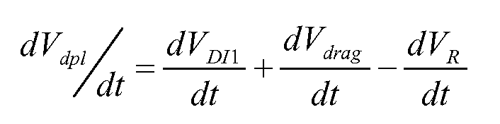
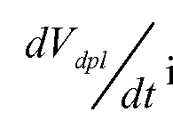
- the method may further include determining the etchant bath discharge rate, oxidizing agent replenishment rate, metal complexing agent replenishment rate, and the recycle rate to maintain concentration as follows:
- [0050] is the etchant bath discharge rate
- [0051] is the metalized substrate feed rate
- substrate is the thickness of metal on the substrate, is the density of the metal, and
- P is a scaling factor for the % of metal etched;
- [0054] is the steady state concentration of metal in the etchant bath;
- [0056] is the rate of etchant bath loss due to dragout, defined as is the rate clean water nnse is discharged onto the
- wwhheerree is the change of the fluid level in a standpipe between the first rinse
- a level sensing device such as a Flowline Echopod ultrasonic level sensor
- [0059] is the rate of etchant bath loss to vaporization
- [0061] is the rate of loss of the metal complexing agent due to one or more side
- [0062] is a stoichiometry constant for the metal complexing agent in the primary etching reaction
- [0063] is the rate of change of the concentration of the metal
- [0064] is the volume of the etchant bath
- [0066] is the concentration of the metal complexing agent in the drag out rinse
- [0068] is the rate of replenishment of the oxidizing agent
- [0069] is the rate of loss of the oxidizing agent due to one or more side reactions
- [0072] is the concentration of the oxidizing agent in the replenishment feed.
- a roll to roll etch system as generally described above, utilizing spray delivery of an etch solution with an eight foot residence distance within an etching zone was used to remove silver from a patterned, 10" wide PET substrate, such as Dupont ST504. Prior to etching, the substrate was sputter-coated with silver at a thickness of approximately 100 nm using a vacuum coating apparatus, such as one available from General Vacuum Equipment, Ltd, and subsequently patterned with alkanethiol, as generally described above. In order to determine pump rates in accord with the methods of the present disclosure, the percent areal coverage of alkanethiol on the silver was determined.
- the etching solution of this example was an aqueous solution of 20 mM ferric nitrate (GFS Chemicals, Inc., Powell, OH) and 30 mM thiourea (GFS Chemicals, Inc., Powell, OH).
- 132 L of the etching solution were prepared within the etch vessel, and the patterned silver was etched at a web rate of 4 feet/minute. From prior experimental data, it was known that undesirable precipitation would occur within the solution at about 400 ppm silver. Therefore, a steady state control method was enforced beginning at 400 ppm silver (220 minutes into the run), as calculated using replenishment and recycle rates, silver coating dimensions, and the percent of silver etched from the substrate.
- Table 1 includes concentrations, pump rates, and other values input or calculated using the equations provided above. Using these conditions, patterned web was etched for 8 hours with no observed precipitation onto the substrate.
- a patterned silver substrate substantially similar to that of Example 1 was etched, as described in Example 1, with a web rate of 6.7 feet/minute using a 40 mM ferric nitrate, 60 mM thiourea aqueous solution. Steady state was enforced beginning at 453 ppm silver (150 minutes into the run) and the run proceeded for a total of 3 hours with no precipitation observed. Pump rates and other values are shown in Table 2.
- a patterned silver substrate substantially similar to that of Example 1 was etched, as described in Example 1, with a web rate of 3.0 feet/minute using a 1 : 1 blend of Part A and Part B of RA-2SM bleach fix (Kodak, Rochester, NY) diluted 9: 1 DI water: bleach fix.
- the bleach fix portion of the solution was a 1 : 1 blend of Part A, an aqueous solution of primarily ammonium thiosulfate, and Part B, an aqueous solution of primarily ferric ammonium ethylene diaminetetraacetic acid (ferric ammonium EDTA).
- the system was run in pre-steady state for the duration of the run.
Landscapes
- Chemical & Material Sciences (AREA)
- Engineering & Computer Science (AREA)
- Organic Chemistry (AREA)
- Chemical Kinetics & Catalysis (AREA)
- General Chemical & Material Sciences (AREA)
- Materials Engineering (AREA)
- Mechanical Engineering (AREA)
- Metallurgy (AREA)
- Manufacturing & Machinery (AREA)
- Microelectronics & Electronic Packaging (AREA)
- Physics & Mathematics (AREA)
- Hydrology & Water Resources (AREA)
- Environmental & Geological Engineering (AREA)
- Water Supply & Treatment (AREA)
- Life Sciences & Earth Sciences (AREA)
- Thermal Sciences (AREA)
- ing And Chemical Polishing (AREA)
- Manufacturing Of Printed Circuit Boards (AREA)
Abstract
Description








Claims
Priority Applications (6)
| Application Number | Priority Date | Filing Date | Title |
|---|---|---|---|
| KR1020147011348A KR101999871B1 (en) | 2011-09-30 | 2012-09-19 | Methods of continuously wet etching a patterned substrate |
| CN201280048262.4A CN103842553B (en) | 2011-09-30 | 2012-09-19 | Sequential wet etching method of patterned substrate |
| SG11201400767WA SG11201400767WA (en) | 2011-09-30 | 2012-09-19 | Methods of continuously wet etching a patterned substrate |
| BR112014007582A BR112014007582A2 (en) | 2011-09-30 | 2012-09-19 | continuous wet grinding methods of a shaped substrate |
| US14/238,781 US9301397B2 (en) | 2011-09-30 | 2012-09-19 | Methods of continuously wet etching a patterned substrate |
| EP12769559.1A EP2761059A1 (en) | 2011-09-30 | 2012-09-19 | Methods of continuously wet etching a patterned substrate |
Applications Claiming Priority (2)
| Application Number | Priority Date | Filing Date | Title |
|---|---|---|---|
| US201161541553P | 2011-09-30 | 2011-09-30 | |
| US61/541,553 | 2011-09-30 |
Publications (1)
| Publication Number | Publication Date |
|---|---|
| WO2013048834A1 true WO2013048834A1 (en) | 2013-04-04 |
Family
ID=46982953
Family Applications (1)
| Application Number | Title | Priority Date | Filing Date |
|---|---|---|---|
| PCT/US2012/055997 Ceased WO2013048834A1 (en) | 2011-09-30 | 2012-09-19 | Methods of continuously wet etching a patterned substrate |
Country Status (8)
| Country | Link |
|---|---|
| US (1) | US9301397B2 (en) |
| EP (1) | EP2761059A1 (en) |
| KR (1) | KR101999871B1 (en) |
| CN (1) | CN103842553B (en) |
| BR (1) | BR112014007582A2 (en) |
| SG (1) | SG11201400767WA (en) |
| TW (1) | TWI560765B (en) |
| WO (1) | WO2013048834A1 (en) |
Cited By (1)
| Publication number | Priority date | Publication date | Assignee | Title |
|---|---|---|---|---|
| CN113802119A (en) * | 2021-08-31 | 2021-12-17 | 煤炭科学研究总院 | Fabrication process of high-precision metal microelectrodes for general PDMS flexible sensors |
Families Citing this family (3)
| Publication number | Priority date | Publication date | Assignee | Title |
|---|---|---|---|---|
| TWI611490B (en) * | 2017-01-20 | 2018-01-11 | Wet etching processing system and method for detecting etch rate change | |
| CN112271135B (en) * | 2020-09-25 | 2023-02-28 | 华东光电集成器件研究所 | Wafer-level Au metal film wet etching patterning method |
| JP7712104B2 (en) * | 2021-05-11 | 2025-07-23 | 株式会社ディスコ | Substrate processing method |
Citations (7)
| Publication number | Priority date | Publication date | Assignee | Title |
|---|---|---|---|---|
| US3475242A (en) * | 1966-12-19 | 1969-10-28 | Fmc Corp | Process and apparatus for controlling metal etching operation |
| US3844857A (en) * | 1972-10-30 | 1974-10-29 | Fmc Corp | Automatic process of etching copper circuits with an aqueous ammoniacal solution containing a salt of a chloroxy acid |
| GB1400510A (en) * | 1972-07-26 | 1975-07-16 | Southern California Chem Co | Continuous redox process for dissolving copper |
| US5221421A (en) * | 1992-03-25 | 1993-06-22 | Hewlett-Packard Company | Controlled etching process for forming fine-geometry circuit lines on a substrate |
| WO2006061741A2 (en) * | 2004-12-06 | 2006-06-15 | Koninklijke Philips Electronics N.V. | Etchant solutions and additives therefor |
| EP1780309A1 (en) * | 2005-10-25 | 2007-05-02 | Atotech Deutschland Gmbh | Composition and method for improved adhesion of polymeric materials to copper or copper alloy surfaces |
| WO2010151471A1 (en) | 2009-06-25 | 2010-12-29 | 3M Innovative Properties Company | Methods of wet etching a self-assembled monolayer patterned substrate and metal patterned articles |
Family Cites Families (14)
| Publication number | Priority date | Publication date | Assignee | Title |
|---|---|---|---|---|
| US3287191A (en) | 1963-07-23 | 1966-11-22 | Photo Engravers Res Inc | Etching of printed circuit components |
| US3340195A (en) | 1964-11-16 | 1967-09-05 | Photo Engravers Res Inc | Process of etching |
| US3905827A (en) * | 1971-10-18 | 1975-09-16 | Chemcut Corp | Etchant rinse method |
| NL7414149A (en) | 1974-10-29 | 1976-05-04 | Leuven Res & Dev Vzw | PROCEDURE FOR RECOVERING SILVER FROM SOLUTIONS. |
| DE4015141A1 (en) | 1990-05-11 | 1991-11-14 | Lpw Anlagen Gmbh | Galvanic process operation using pre- and post-treatment baths - involves continuously or cyclically supplying fresh liq. whose life is limited by continuous operation |
| CA2041062C (en) | 1991-02-14 | 2000-11-28 | D. Gregory Beckett | Demetallizing procedure |
| DE19600857A1 (en) | 1996-01-12 | 1997-07-17 | Atotech Deutschland Gmbh | Process dosing process baths |
| US8092707B2 (en) * | 1997-04-30 | 2012-01-10 | 3M Innovative Properties Company | Compositions and methods for modifying a surface suited for semiconductor fabrication |
| US6150279A (en) | 1998-06-23 | 2000-11-21 | Ku; Amy | Reverse current gold etch |
| US6841084B2 (en) | 2002-02-11 | 2005-01-11 | Nikko Materials Usa, Inc. | Etching solution for forming an embedded resistor |
| JP4098669B2 (en) * | 2003-05-27 | 2008-06-11 | 日本パーカライジング株式会社 | Recovery and reuse of phosphate chemical conversion solution |
| US7677198B2 (en) * | 2005-11-28 | 2010-03-16 | Industrial Technology Research Institute | Method and apparatus for growing a composite metal sulphide photocatalyst thin film |
| US20070269750A1 (en) * | 2006-05-19 | 2007-11-22 | Eastman Kodak Company | Colored masking for forming transparent structures |
| JP2009210972A (en) * | 2008-03-06 | 2009-09-17 | Jsr Corp | Transfer film and pattern forming method |
-
2012
- 2012-09-19 WO PCT/US2012/055997 patent/WO2013048834A1/en not_active Ceased
- 2012-09-19 BR BR112014007582A patent/BR112014007582A2/en not_active IP Right Cessation
- 2012-09-19 EP EP12769559.1A patent/EP2761059A1/en not_active Withdrawn
- 2012-09-19 CN CN201280048262.4A patent/CN103842553B/en not_active Expired - Fee Related
- 2012-09-19 US US14/238,781 patent/US9301397B2/en not_active Expired - Fee Related
- 2012-09-19 KR KR1020147011348A patent/KR101999871B1/en not_active Expired - Fee Related
- 2012-09-19 SG SG11201400767WA patent/SG11201400767WA/en unknown
- 2012-09-28 TW TW101136052A patent/TWI560765B/en not_active IP Right Cessation
Patent Citations (8)
| Publication number | Priority date | Publication date | Assignee | Title |
|---|---|---|---|---|
| US3475242A (en) * | 1966-12-19 | 1969-10-28 | Fmc Corp | Process and apparatus for controlling metal etching operation |
| GB1400510A (en) * | 1972-07-26 | 1975-07-16 | Southern California Chem Co | Continuous redox process for dissolving copper |
| US3844857A (en) * | 1972-10-30 | 1974-10-29 | Fmc Corp | Automatic process of etching copper circuits with an aqueous ammoniacal solution containing a salt of a chloroxy acid |
| US5221421A (en) * | 1992-03-25 | 1993-06-22 | Hewlett-Packard Company | Controlled etching process for forming fine-geometry circuit lines on a substrate |
| WO2006061741A2 (en) * | 2004-12-06 | 2006-06-15 | Koninklijke Philips Electronics N.V. | Etchant solutions and additives therefor |
| EP1780309A1 (en) * | 2005-10-25 | 2007-05-02 | Atotech Deutschland Gmbh | Composition and method for improved adhesion of polymeric materials to copper or copper alloy surfaces |
| WO2010151471A1 (en) | 2009-06-25 | 2010-12-29 | 3M Innovative Properties Company | Methods of wet etching a self-assembled monolayer patterned substrate and metal patterned articles |
| US20120082825A1 (en) | 2009-06-25 | 2012-04-05 | Lijun Zu | Methods of wet etching a self-assembled monolayer patterned substrate and metal patterned articles |
Non-Patent Citations (1)
| Title |
|---|
| RASBAND, W.S.: "ImageJ", 1997, U. S. NATIONAL INSTITUTES OF HEALTH |
Cited By (1)
| Publication number | Priority date | Publication date | Assignee | Title |
|---|---|---|---|---|
| CN113802119A (en) * | 2021-08-31 | 2021-12-17 | 煤炭科学研究总院 | Fabrication process of high-precision metal microelectrodes for general PDMS flexible sensors |
Also Published As
| Publication number | Publication date |
|---|---|
| CN103842553A (en) | 2014-06-04 |
| EP2761059A1 (en) | 2014-08-06 |
| TW201320180A (en) | 2013-05-16 |
| KR101999871B1 (en) | 2019-10-01 |
| BR112014007582A2 (en) | 2017-04-11 |
| US20140231381A1 (en) | 2014-08-21 |
| TWI560765B (en) | 2016-12-01 |
| US9301397B2 (en) | 2016-03-29 |
| SG11201400767WA (en) | 2014-04-28 |
| KR20140074364A (en) | 2014-06-17 |
| CN103842553B (en) | 2016-04-27 |
Similar Documents
| Publication | Publication Date | Title |
|---|---|---|
| EP2446067B1 (en) | Methods of wet etching a self-assembled monolayer patterned substrate and metal patterned articles | |
| US9301397B2 (en) | Methods of continuously wet etching a patterned substrate | |
| TWI310792B (en) | ||
| JP5358145B2 (en) | Conductive material manufacturing method and conductive material manufacturing apparatus | |
| US12186769B2 (en) | Spray coating device and spray coating method | |
| TWI486488B (en) | Copper or copper alloy etching solution, etching method and etching solution management method | |
| JPH05222540A (en) | How to extend the life of displacement plating baths | |
| US20220117092A1 (en) | Continuous etching system | |
| EP2591142B1 (en) | Method and arrangement for depositing a metal coating | |
| Kao et al. | Etch profile development in spray etching processes | |
| US20160040290A1 (en) | Roll-to-roll electroless plating system for controlled substrate depth | |
| JP3320111B2 (en) | Etching method | |
| JP2009256757A (en) | Film support device and apparatus for forming film with plated coating | |
| JP2780092B2 (en) | A method for maintaining the capacity of the etching solution | |
| US20160040294A1 (en) | Method of controlling oxygen levels for electroless plating of catalytic fine lines or features | |
| JP2004300538A (en) | Plating method and device | |
| JP2006080342A (en) | Method for etching copper | |
| JPH03223475A (en) | Method and device for chemical etching for metal | |
| PLATING | PATENTS GRANTED | |
| JP2002141638A (en) | Etching treatment device of printed-wiring board, and etching treatment method for printed-wiring board using the same | |
| WO2016022147A1 (en) | Method of controlling oxygen levels for electroless plating of catalytic fine lines or features | |
| HK1237381A1 (en) | Oxidation of copper in a copper etching solution by the use of oxygen and/or air as an oxidizing agent |
Legal Events
| Date | Code | Title | Description |
|---|---|---|---|
| WWE | Wipo information: entry into national phase |
Ref document number: 201280048262.4 Country of ref document: CN |
|
| 121 | Ep: the epo has been informed by wipo that ep was designated in this application |
Ref document number: 12769559 Country of ref document: EP Kind code of ref document: A1 |
|
| WWE | Wipo information: entry into national phase |
Ref document number: 14238781 Country of ref document: US |
|
| WWE | Wipo information: entry into national phase |
Ref document number: 2012769559 Country of ref document: EP |
|
| NENP | Non-entry into the national phase |
Ref country code: DE |
|
| ENP | Entry into the national phase |
Ref document number: 20147011348 Country of ref document: KR Kind code of ref document: A |
|
| REG | Reference to national code |
Ref country code: BR Ref legal event code: B01A Ref document number: 112014007582 Country of ref document: BR |
|
| ENP | Entry into the national phase |
Ref document number: 112014007582 Country of ref document: BR Kind code of ref document: A2 Effective date: 20140328 |