WO2013051233A1 - 熱交換器用チューブ - Google Patents
熱交換器用チューブ Download PDFInfo
- Publication number
- WO2013051233A1 WO2013051233A1 PCT/JP2012/006287 JP2012006287W WO2013051233A1 WO 2013051233 A1 WO2013051233 A1 WO 2013051233A1 JP 2012006287 W JP2012006287 W JP 2012006287W WO 2013051233 A1 WO2013051233 A1 WO 2013051233A1
- Authority
- WO
- WIPO (PCT)
- Prior art keywords
- circular
- tube
- exhaust gas
- heat exchanger
- swirl flow
- Prior art date
- Legal status (The legal status is an assumption and is not a legal conclusion. Google has not performed a legal analysis and makes no representation as to the accuracy of the status listed.)
- Ceased
Links
Images


Classifications
-
- F—MECHANICAL ENGINEERING; LIGHTING; HEATING; WEAPONS; BLASTING
- F28—HEAT EXCHANGE IN GENERAL
- F28F—DETAILS OF HEAT-EXCHANGE AND HEAT-TRANSFER APPARATUS, OF GENERAL APPLICATION
- F28F1/00—Tubular elements; Assemblies of tubular elements
- F28F1/10—Tubular elements and assemblies thereof with means for increasing heat-transfer area, e.g. with fins, with projections, with recesses
- F28F1/40—Tubular elements and assemblies thereof with means for increasing heat-transfer area, e.g. with fins, with projections, with recesses the means being only inside the tubular element
-
- F—MECHANICAL ENGINEERING; LIGHTING; HEATING; WEAPONS; BLASTING
- F02—COMBUSTION ENGINES; HOT-GAS OR COMBUSTION-PRODUCT ENGINE PLANTS
- F02M—SUPPLYING COMBUSTION ENGINES IN GENERAL WITH COMBUSTIBLE MIXTURES OR CONSTITUENTS THEREOF
- F02M26/00—Engine-pertinent apparatus for adding exhaust gases to combustion-air, main fuel or fuel-air mixture, e.g. by exhaust gas recirculation [EGR] systems
- F02M26/13—Arrangement or layout of EGR passages, e.g. in relation to specific engine parts or for incorporation of accessories
- F02M26/22—Arrangement or layout of EGR passages, e.g. in relation to specific engine parts or for incorporation of accessories with coolers in the recirculation passage
- F02M26/29—Constructional details of the coolers, e.g. pipes, plates, ribs, insulation or materials
- F02M26/32—Liquid-cooled heat exchangers
-
- F—MECHANICAL ENGINEERING; LIGHTING; HEATING; WEAPONS; BLASTING
- F28—HEAT EXCHANGE IN GENERAL
- F28F—DETAILS OF HEAT-EXCHANGE AND HEAT-TRANSFER APPARATUS, OF GENERAL APPLICATION
- F28F1/00—Tubular elements; Assemblies of tubular elements
- F28F1/02—Tubular elements of cross-section which is non-circular
- F28F1/06—Tubular elements of cross-section which is non-circular crimped or corrugated in cross-section
-
- F—MECHANICAL ENGINEERING; LIGHTING; HEATING; WEAPONS; BLASTING
- F28—HEAT EXCHANGE IN GENERAL
- F28F—DETAILS OF HEAT-EXCHANGE AND HEAT-TRANSFER APPARATUS, OF GENERAL APPLICATION
- F28F1/00—Tubular elements; Assemblies of tubular elements
- F28F1/08—Tubular elements crimped or corrugated in longitudinal section
-
- F—MECHANICAL ENGINEERING; LIGHTING; HEATING; WEAPONS; BLASTING
- F28—HEAT EXCHANGE IN GENERAL
- F28F—DETAILS OF HEAT-EXCHANGE AND HEAT-TRANSFER APPARATUS, OF GENERAL APPLICATION
- F28F1/00—Tubular elements; Assemblies of tubular elements
- F28F1/10—Tubular elements and assemblies thereof with means for increasing heat-transfer area, e.g. with fins, with projections, with recesses
- F28F1/42—Tubular elements and assemblies thereof with means for increasing heat-transfer area, e.g. with fins, with projections, with recesses the means being both outside and inside the tubular element
- F28F1/424—Means comprising outside portions integral with inside portions
- F28F1/426—Means comprising outside portions integral with inside portions the outside portions and the inside portions forming parts of complementary shape, e.g. concave and convex
-
- F—MECHANICAL ENGINEERING; LIGHTING; HEATING; WEAPONS; BLASTING
- F28—HEAT EXCHANGE IN GENERAL
- F28F—DETAILS OF HEAT-EXCHANGE AND HEAT-TRANSFER APPARATUS, OF GENERAL APPLICATION
- F28F13/00—Arrangements for modifying heat-transfer, e.g. increasing, decreasing
- F28F13/06—Arrangements for modifying heat-transfer, e.g. increasing, decreasing by affecting the pattern of flow of the heat-exchange media
- F28F13/12—Arrangements for modifying heat-transfer, e.g. increasing, decreasing by affecting the pattern of flow of the heat-exchange media by creating turbulence, e.g. by stirring, by increasing the force of circulation
-
- F—MECHANICAL ENGINEERING; LIGHTING; HEATING; WEAPONS; BLASTING
- F28—HEAT EXCHANGE IN GENERAL
- F28D—HEAT-EXCHANGE APPARATUS, NOT PROVIDED FOR IN ANOTHER SUBCLASS, IN WHICH THE HEAT-EXCHANGE MEDIA DO NOT COME INTO DIRECT CONTACT
- F28D21/00—Heat-exchange apparatus not covered by any of the groups F28D1/00 - F28D20/00
- F28D21/0001—Recuperative heat exchangers
- F28D21/0003—Recuperative heat exchangers the heat being recuperated from exhaust gases
-
- F—MECHANICAL ENGINEERING; LIGHTING; HEATING; WEAPONS; BLASTING
- F28—HEAT EXCHANGE IN GENERAL
- F28D—HEAT-EXCHANGE APPARATUS, NOT PROVIDED FOR IN ANOTHER SUBCLASS, IN WHICH THE HEAT-EXCHANGE MEDIA DO NOT COME INTO DIRECT CONTACT
- F28D7/00—Heat-exchange apparatus having stationary tubular conduit assemblies for both heat-exchange media, the media being in contact with different sides of a conduit wall
- F28D7/16—Heat-exchange apparatus having stationary tubular conduit assemblies for both heat-exchange media, the media being in contact with different sides of a conduit wall the conduits being arranged in parallel spaced relation
- F28D7/1684—Heat-exchange apparatus having stationary tubular conduit assemblies for both heat-exchange media, the media being in contact with different sides of a conduit wall the conduits being arranged in parallel spaced relation the conduits having a non-circular cross-section
Definitions
- the present invention relates to a heat exchanger tube that can be used in a heat exchanger such as an EGR cooler.
- an EGR device that reduces the generation of nitrogen oxides by recirculating a part of exhaust gas of an engine such as an automobile to the engine.
- the exhaust gas recirculated to the engine is known.
- the temperature of the exhaust gas is reduced and the volume of the exhaust gas is reduced, so that the combustion temperature can be lowered and the generation of nitrogen oxides can be effectively reduced without significantly reducing the output of the engine.
- Some engines are equipped with an EGR cooler for cooling the exhaust gas in the middle of the line for recirculating the exhaust gas to the engine.
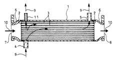
- FIG. 1 is a cross-sectional view showing an example of the EGR cooler.
- reference numeral 1 denotes a shell formed in a cylindrical shape, and a plate is formed on both ends of the shell 1 in the axial direction so as to close the end face of the shell 1.
- 2 and 2 are fixed, and both ends of a large number of tubes 3 are fixed to the respective plates 2 and 2 in a penetrating state.
- the large numbers of tubes 3 extend in the axial direction inside the shell 1. Yes.
- a cooling water inlet pipe 4 is attached from the outside near one end of the shell 1, and a cooling water outlet pipe 5 is attached from the outside near the other end of the shell 1. 9 is supplied from the cooling water inlet pipe 4 to the inside of the shell 1, flows outside the tube 3, and is discharged from the cooling water outlet pipe 5 to the outside of the shell 1.
- bonnets 6, 6 formed in a bowl shape are fixed to the opposite shell 1 side of each plate 2, 2 so as to enclose the end faces of the respective plates 2, 2, and in the center of one bonnet 6.
- the exhaust gas 10 of the engine enters the inside of one bonnet 6 from the exhaust gas inlet 7, and a plurality of tubes 3. After being cooled by heat exchange with the cooling water 9 flowing outside the tube 3, it is discharged into the other bonnet 6 and recirculated from the exhaust gas outlet 8 to the engine.
- reference numeral 11 denotes a bypass outlet pipe provided at a position facing the cooling water inlet pipe 4 in the diameter direction of the shell 1.
- the spiral protrusion 12 is formed on the inner peripheral surface of the tube 3 (the spiral protrusion 12 is formed on the inner peripheral surface side as an inverted shape by recessing the outer peripheral surface side of the tube 3 as a spiral groove). It has already been proposed to improve the heat exchange efficiency of the EGR cooler by making the exhaust gas 10 flowing inside the swirl flow and thereby increasing the contact frequency and contact distance of the exhaust gas 10 with respect to the inner peripheral surface of the tube 3 ( For example, refer to Patent Document 1 and Patent Document 2.)
- Patent Documents 1 and 2 As prior art document information related to this type of heat exchanger tube, there are the following Patent Documents 1 and 2 and the like.
- the present invention has been made in view of the above-described circumstances, and in the same way as in the past, a swirl flow is imparted to the exhaust gas to achieve a high heat exchange efficiency, while the heat exchange amount per unit volume can be significantly improved. It aims at providing the tube for heat exchangers.
- the present invention comprises a flat tube body having a shape such that a plurality of circular tubes are arranged close to each other in a plane and connected to each other as a communicating portion, and corresponds to the circular tube of the flat tube body.
- the swirl flow forming projections can be formed on the inner peripheral surface of the circular tube portion along the spiral orbit concentric with the central axis of the circular tube portion, and the swirl flow of the heat medium can be individually formed in each circular tube portion. It is related with the tube for heat exchangers characterized by having constituted as mentioned above.
- the direction of the swirl flow forming projections of the adjacent circular pipe portions is formed so as to be along the spiral trajectories that are opposite to each other.
- the swirl flows in the same direction flow in the same direction and accelerate each other, and even if there is a communication part between each circular pipe part, it is possible to more reliably form the heat medium as a swirl flow Become.
- the heat exchange amount per unit volume can be greatly improved compared to the conventional one while giving a swirl flow to the heat medium and realizing high heat exchange efficiency as in the past, and to a heat exchanger such as an EGR cooler.
- the overall configuration of the heat exchanger can be made compact to improve the mountability on a vehicle or the like.
- FIG. 3 is a perspective view of a prototype example in which the tube of FIG. 2 is flattened. It is a perspective view which shows the Example of this invention. It is sectional drawing of the flat tube main body of FIG. It is sectional drawing which shows schematically the example of application to an EGR cooler.
- FIGS. 4 and 5 show an embodiment of the heat exchanger tube of the present invention, which shows a case where it is applied to an EGR cooler as in the case of the above-described conventional example, and the same reference numerals as in FIGS. The parts marked with indicate the same thing.
- a flat tube having a shape in which a plurality of circular tubes are arranged close to each other and arranged in a plane, and adjacent portions between them are connected as a communication portion 13.
- a swirl flow forming protrusion 16 is formed on the inner peripheral surface of the circular tube portion 15 corresponding to the circular tube of the flat tube main body 14 along a spiral orbit concentric with the central axis O of the circular tube portion 15.
- the swirl flow forming projections 16 are formed in a reverse shape by recessing the outer peripheral surface side of each circular pipe portion 15 into a groove shape, and the swirl flow of the exhaust gas 10 is individually formed in each circular pipe portion 15. Configure to get.
- the direction of the swirl flow forming projections 16 of the adjacent circular pipe portions 15 is formed so as to be along mutually opposite spiral trajectories (for each circular pipe portion 15 in FIG. 4). (Refer to the external appearance), and it is devised so that the swirl flows are made to flow in the same direction at the communicating portions 13 of the adjacent circular pipe portions 15 so that the mutual flows do not cancel each other (exhaust gas indicated by arrows in FIG. 5). See direction of swirl flow of gas 10).
- each circular tube portion 15 is recessed in a groove shape, and the swirl flow forming protrusion 16 may be raised as an inverted shape on the inner peripheral surface side.
- the swirl flow formation protrusion 16 of the said side part is provided.
- This processing (groove processing from the outer peripheral surface side: see FIG. 4) may be partially omitted, and even if the partial swirl flow forming protrusion 16 is omitted here, the swirl flow formation is greatly affected.
- the inventors of the present application have confirmed that it is not necessary to provide this.
- the heat exchanger tube when the heat exchanger tube is configured as described above, when the exhaust gas 10 flows through each circular pipe portion 15 of the flat tube main body 14, the swirl flow forming protrusion on the inner peripheral surface of each circular pipe portion 15 is provided. 16, the flow is guided in the direction along the spiral trajectory, and as a result, the swirling flow of the exhaust gas 10 is individually formed in each circular pipe portion 15. As a result, the exhaust gas 10 with respect to the inner peripheral surface of each circular pipe portion 15 is formed. Since the contact frequency and the contact distance are increased, the heat exchange efficiency is improved, and the circular pipe parts 15 are in communication with each other via the communication part 13 and the exhaust gas 10 circulates. Since the flow passage cross-sectional area is ensured to be large, the amount of exchange heat per unit volume is increased, and the pressure loss is reduced.
- the direction of the swirl flow forming projections 16 of the adjacent circular pipe portions 15 is formed so as to follow the spiral trajectories that are opposite to each other.
- the amount of heat exchange per unit volume can be significantly improved compared to the conventional one while giving a swirl flow to the exhaust gas 10 and realizing high heat exchange efficiency as in the conventional example.
- the flat tube main body 14 as described above is divided into a plurality of rows (two rows in the illustrated example) and arranged in multiple stages (nine stages in the illustrated example) with respect to the shell 1 having a rectangular cross section. If it is made to accommodate, even if it increases the recirculation amount of the exhaust gas 10 more than before, and raises an EGR rate, the whole structure of an EGR cooler can be suppressed compactly and the mounting property to a vehicle can be improved. .
- the direction of the swirl flow forming projections 16 of the adjacent circular pipe portions 15 is formed so as to follow the spiral trajectories opposite to each other.
- the swirl flows can be accelerated in the same direction as each other, and the formation of the swirl flow in each circular pipe portion 15 can be made more reliable.
- the heat exchanger tube of the present invention is not limited to the above-described embodiment, but may be applied to a heat exchanger other than the EGR cooler, and other within the scope not departing from the gist of the present invention. Of course, various changes can be made.
Landscapes
- Engineering & Computer Science (AREA)
- Physics & Mathematics (AREA)
- Mechanical Engineering (AREA)
- General Engineering & Computer Science (AREA)
- Thermal Sciences (AREA)
- Geometry (AREA)
- Chemical & Material Sciences (AREA)
- Combustion & Propulsion (AREA)
- Exhaust-Gas Circulating Devices (AREA)
- Heat-Exchange Devices With Radiators And Conduit Assemblies (AREA)
Abstract
Description
13 連通部
14 偏平チューブ本体
15 円管部
16 旋回流形成突起
Claims (2)
- 複数本の円管を互いに近接させて平面状に並べ且つその相互間の近接部位を連通部として接続した如き形状の偏平チューブ本体から成り、該偏平チューブ本体の前記円管に相当する円管部の内周面に該円管部の中心軸と同心の螺旋軌道に沿うように旋回流形成突起を形成し、前記各円管部に個別に熱媒体の旋回流を形成し得るように構成した熱交換器用チューブ。
- 隣り合う円管部の旋回流形成突起の向きが、互いに逆向きの螺旋軌道に沿うように形成されている請求項1に記載の熱交換器用チューブ。
Priority Applications (4)
| Application Number | Priority Date | Filing Date | Title |
|---|---|---|---|
| CN201280045153.7A CN103814268B (zh) | 2011-10-05 | 2012-10-02 | 热交换器用管 |
| US14/343,271 US10422589B2 (en) | 2011-10-05 | 2012-10-02 | Heat exchanger tube |
| AU2012319958A AU2012319958B2 (en) | 2011-10-05 | 2012-10-02 | Heat exchanger tube |
| EP12837673.8A EP2765384B1 (en) | 2011-10-05 | 2012-10-02 | Heat exchanger tube |
Applications Claiming Priority (2)
| Application Number | Priority Date | Filing Date | Title |
|---|---|---|---|
| JP2011-220778 | 2011-10-05 | ||
| JP2011220778A JP5850693B2 (ja) | 2011-10-05 | 2011-10-05 | 熱交換器用チューブ |
Publications (1)
| Publication Number | Publication Date |
|---|---|
| WO2013051233A1 true WO2013051233A1 (ja) | 2013-04-11 |
Family
ID=48043416
Family Applications (1)
| Application Number | Title | Priority Date | Filing Date |
|---|---|---|---|
| PCT/JP2012/006287 Ceased WO2013051233A1 (ja) | 2011-10-05 | 2012-10-02 | 熱交換器用チューブ |
Country Status (6)
| Country | Link |
|---|---|
| US (1) | US10422589B2 (ja) |
| EP (1) | EP2765384B1 (ja) |
| JP (1) | JP5850693B2 (ja) |
| CN (1) | CN103814268B (ja) |
| AU (1) | AU2012319958B2 (ja) |
| WO (1) | WO2013051233A1 (ja) |
Cited By (2)
| Publication number | Priority date | Publication date | Assignee | Title |
|---|---|---|---|---|
| CN103644755A (zh) * | 2013-11-27 | 2014-03-19 | 华南理工大学 | 一种传热管和使用该传热管的气体换热器 |
| CN104101235A (zh) * | 2014-07-31 | 2014-10-15 | 洛阳明远石化技术有限公司 | 管板式换热器 |
Families Citing this family (16)
| Publication number | Priority date | Publication date | Assignee | Title |
|---|---|---|---|---|
| JP6193653B2 (ja) * | 2013-07-09 | 2017-09-06 | 日野自動車株式会社 | Egrクーラ |
| FR3020670B1 (fr) * | 2014-05-05 | 2019-03-22 | Valeo Systemes Thermiques | Tube plat pour echangeur de chaleur |
| CN104534897A (zh) * | 2014-12-29 | 2015-04-22 | 浙江华森散热器制造有限公司 | 胀管式汽车散热器 |
| KR102176470B1 (ko) * | 2015-01-13 | 2020-11-09 | 한온시스템 주식회사 | 배기가스 재순환 쿨러 |
| KR102150606B1 (ko) * | 2015-01-14 | 2020-09-01 | 한온시스템 주식회사 | 배기가스 재순환 쿨러 |
| JP6463993B2 (ja) * | 2015-03-04 | 2019-02-06 | 日野自動車株式会社 | 熱交換器用チューブ |
| CN104864758A (zh) * | 2015-06-10 | 2015-08-26 | 纳百川控股有限公司 | 热交换器管道及热交换器 |
| CN108474629B (zh) * | 2015-12-28 | 2021-11-02 | 开利公司 | 用于热交换器应用的折叠导管 |
| ES2676708B1 (es) * | 2017-01-23 | 2019-05-14 | Valeo Termico Sa | Intercambiador de calor para gases |
| CN106855367B (zh) * | 2017-02-28 | 2024-01-26 | 郑州大学 | 具有分布性出入口的管壳式换热器 |
| CN106679467B (zh) * | 2017-02-28 | 2019-04-05 | 郑州大学 | 具有外接管箱的管壳式换热器 |
| TWI719309B (zh) * | 2018-05-16 | 2021-02-21 | 寶成工業股份有限公司 | 發泡模具裝置 |
| US11573053B2 (en) * | 2019-08-13 | 2023-02-07 | General Electric Company | Cyclone cooler device |
| JP6868146B1 (ja) * | 2020-06-29 | 2021-05-12 | 株式会社クボタ | 流体撹拌要素を具える熱分解管 |
| US20220260316A1 (en) * | 2020-12-16 | 2022-08-18 | Meggitt Aerospace Limited | Cross-flow heat exchangers and methods of making the same |
| FI131891B1 (en) * | 2021-06-29 | 2026-02-02 | Tamturbo Oyj | Compressor |
Citations (9)
| Publication number | Priority date | Publication date | Assignee | Title |
|---|---|---|---|---|
| JP2000345925A (ja) | 1999-06-04 | 2000-12-12 | Hino Motors Ltd | Egrクーラ |
| JP2001254649A (ja) | 2000-03-13 | 2001-09-21 | Hino Motors Ltd | Egrクーラ |
| US6470878B1 (en) * | 2000-10-23 | 2002-10-29 | Carrier Corporation | Furnace heat exchanger |
| JP2006322698A (ja) * | 2005-04-22 | 2006-11-30 | Denso Corp | 熱交換器 |
| JP2007518053A (ja) * | 2004-01-12 | 2007-07-05 | ジーパック | 熱交換器およびその熱交換モジュール |
| WO2008029639A1 (en) * | 2006-09-08 | 2008-03-13 | Tsinghua University | Corrugated heat exchanger tube for hot water supply |
| JP2008232142A (ja) * | 2007-02-20 | 2008-10-02 | Usui Kokusai Sangyo Kaisha Ltd | クールドegrシステム及び該システム用熱交換器 |
| JP2008232600A (ja) * | 2007-03-23 | 2008-10-02 | Mitsubishi Electric Corp | 熱交換器及びこの熱交換器を備えた空気調和機 |
| JP2009270755A (ja) * | 2008-05-07 | 2009-11-19 | Sumitomo Light Metal Ind Ltd | 熱交換器用伝熱管及びそれを用いた熱交換器 |
Family Cites Families (17)
| Publication number | Priority date | Publication date | Assignee | Title |
|---|---|---|---|---|
| US2093256A (en) * | 1935-01-10 | 1937-09-14 | Still William Joseph | Heat exchange element |
| US3119446A (en) * | 1959-09-17 | 1964-01-28 | American Thermocatalytic Corp | Heat exchangers |
| DE1451229A1 (de) | 1963-10-04 | 1969-10-09 | Huetoegepgyar | Waermeaustauscher |
| US3584682A (en) * | 1968-07-29 | 1971-06-15 | Borg Warner | Tubular heat transfer device |
| US4274186A (en) * | 1978-05-26 | 1981-06-23 | United States Steel Corporation | Heat exchanger |
| US5178124A (en) | 1991-08-12 | 1993-01-12 | Rheem Manufacturing Company | Plastic secondary heat exchanger apparatus for a high efficiency condensing furnace |
| US20030111209A1 (en) * | 1999-01-20 | 2003-06-19 | Hino Motors, Ltd. | EGR cooler |
| FR2809483B1 (fr) * | 2000-05-26 | 2003-08-15 | Spirec | Perfectionnements aux echangeurs thermiques de type spirale |
| US6488079B2 (en) * | 2000-12-15 | 2002-12-03 | Packless Metal Hose, Inc. | Corrugated heat exchanger element having grooved inner and outer surfaces |
| DE102004011608A1 (de) | 2004-03-18 | 2005-10-13 | Obrist Engineering Gmbh | Wärmetauscher einer Fahrzeugklimaanlage |
| US7182128B2 (en) * | 2005-03-09 | 2007-02-27 | Visteon Global Technologies, Inc. | Heat exchanger tube having strengthening deformations |
| EP1793164A1 (de) * | 2005-12-05 | 2007-06-06 | Siemens Aktiengesellschaft | Dampferzeugerrohr, zugehöriges Herstellungsverfahren sowie Durchlaufdampferzeuger |
| CN101033925A (zh) * | 2006-03-09 | 2007-09-12 | 北京美联桥科技发展有限公司 | 螺旋凹槽换热管 |
| US7778051B2 (en) * | 2007-03-14 | 2010-08-17 | System General Corp. | Output current control circuit for power converter with a changeable switching frequency |
| US8844472B2 (en) * | 2009-12-22 | 2014-09-30 | Lochinvar, Llc | Fire tube heater |
| EP2365270B1 (en) * | 2010-03-08 | 2014-04-30 | Alfa Laval Corporate AB | A spiral heat exchanger |
| DE102012217333A1 (de) * | 2012-09-25 | 2014-03-27 | Behr Gmbh & Co. Kg | Flachrohr |
-
2011
- 2011-10-05 JP JP2011220778A patent/JP5850693B2/ja not_active Expired - Fee Related
-
2012
- 2012-10-02 WO PCT/JP2012/006287 patent/WO2013051233A1/ja not_active Ceased
- 2012-10-02 CN CN201280045153.7A patent/CN103814268B/zh not_active Expired - Fee Related
- 2012-10-02 EP EP12837673.8A patent/EP2765384B1/en not_active Not-in-force
- 2012-10-02 US US14/343,271 patent/US10422589B2/en not_active Expired - Fee Related
- 2012-10-02 AU AU2012319958A patent/AU2012319958B2/en not_active Ceased
Patent Citations (9)
| Publication number | Priority date | Publication date | Assignee | Title |
|---|---|---|---|---|
| JP2000345925A (ja) | 1999-06-04 | 2000-12-12 | Hino Motors Ltd | Egrクーラ |
| JP2001254649A (ja) | 2000-03-13 | 2001-09-21 | Hino Motors Ltd | Egrクーラ |
| US6470878B1 (en) * | 2000-10-23 | 2002-10-29 | Carrier Corporation | Furnace heat exchanger |
| JP2007518053A (ja) * | 2004-01-12 | 2007-07-05 | ジーパック | 熱交換器およびその熱交換モジュール |
| JP2006322698A (ja) * | 2005-04-22 | 2006-11-30 | Denso Corp | 熱交換器 |
| WO2008029639A1 (en) * | 2006-09-08 | 2008-03-13 | Tsinghua University | Corrugated heat exchanger tube for hot water supply |
| JP2008232142A (ja) * | 2007-02-20 | 2008-10-02 | Usui Kokusai Sangyo Kaisha Ltd | クールドegrシステム及び該システム用熱交換器 |
| JP2008232600A (ja) * | 2007-03-23 | 2008-10-02 | Mitsubishi Electric Corp | 熱交換器及びこの熱交換器を備えた空気調和機 |
| JP2009270755A (ja) * | 2008-05-07 | 2009-11-19 | Sumitomo Light Metal Ind Ltd | 熱交換器用伝熱管及びそれを用いた熱交換器 |
Non-Patent Citations (1)
| Title |
|---|
| See also references of EP2765384A4 |
Cited By (2)
| Publication number | Priority date | Publication date | Assignee | Title |
|---|---|---|---|---|
| CN103644755A (zh) * | 2013-11-27 | 2014-03-19 | 华南理工大学 | 一种传热管和使用该传热管的气体换热器 |
| CN104101235A (zh) * | 2014-07-31 | 2014-10-15 | 洛阳明远石化技术有限公司 | 管板式换热器 |
Also Published As
| Publication number | Publication date |
|---|---|
| CN103814268B (zh) | 2016-03-30 |
| US10422589B2 (en) | 2019-09-24 |
| AU2012319958B2 (en) | 2017-05-04 |
| JP5850693B2 (ja) | 2016-02-03 |
| EP2765384A1 (en) | 2014-08-13 |
| US20140262165A1 (en) | 2014-09-18 |
| CN103814268A (zh) | 2014-05-21 |
| JP2013079779A (ja) | 2013-05-02 |
| EP2765384B1 (en) | 2016-09-14 |
| AU2012319958A1 (en) | 2014-03-20 |
| EP2765384A4 (en) | 2015-07-01 |
Similar Documents
| Publication | Publication Date | Title |
|---|---|---|
| JP5850693B2 (ja) | 熱交換器用チューブ | |
| JP6291474B2 (ja) | 熱交換器 | |
| CA2734455C (en) | Heat exchanger | |
| CN102619648B (zh) | 一种具有隔热功能的板翅式egr冷却器 | |
| US8069905B2 (en) | EGR gas cooling device | |
| US7984753B2 (en) | Heat exchanger | |
| JP2017516975A (ja) | Egrガス差圧低減用ウェーブフィンプレートを有する熱交換器 | |
| JP2009501892A (ja) | 熱交換器 | |
| CN113756912B (zh) | 热交换器 | |
| JP6193653B2 (ja) | Egrクーラ | |
| US20070000652A1 (en) | Heat exchanger with dimpled tube surfaces | |
| JP6463993B2 (ja) | 熱交換器用チューブ | |
| JP2013122367A (ja) | 車両用熱交換器 | |
| EP2764231B1 (en) | Heat exchanger for gases, especially engine exhaust gases | |
| JP2011085315A (ja) | 熱交換器 | |
| JP2007255719A (ja) | 熱交換器の連結構造 | |
| JP2017138013A (ja) | 熱交換器 | |
| JP4221260B2 (ja) | 熱交換器及びその製造方法 | |
| JP2004077024A (ja) | 排気熱交換装置 | |
| JP4681435B2 (ja) | 熱交換器の連結構造 | |
| JP2009024499A (ja) | Egrクーラ | |
| CN201368681Y (zh) | 一种中重型车用废气再循环冷却器 | |
| KR20200120509A (ko) | 인터쿨러 | |
| JP2008089270A (ja) | インタークーラ | |
| JP2014084841A (ja) | 排気熱交換器 |
Legal Events
| Date | Code | Title | Description |
|---|---|---|---|
| WWE | Wipo information: entry into national phase |
Ref document number: 201280045153.7 Country of ref document: CN |
|
| 121 | Ep: the epo has been informed by wipo that ep was designated in this application |
Ref document number: 12837673 Country of ref document: EP Kind code of ref document: A1 |
|
| WWE | Wipo information: entry into national phase |
Ref document number: 14343271 Country of ref document: US |
|
| REEP | Request for entry into the european phase |
Ref document number: 2012837673 Country of ref document: EP |
|
| WWE | Wipo information: entry into national phase |
Ref document number: 2012837673 Country of ref document: EP |
|
| ENP | Entry into the national phase |
Ref document number: 2012319958 Country of ref document: AU Date of ref document: 20121002 Kind code of ref document: A |
|
| NENP | Non-entry into the national phase |
Ref country code: DE |